JP2017195534A - Information processing apparatus, serial communication method, and serial communication program - Google Patents
Information processing apparatus, serial communication method, and serial communication program Download PDFInfo
- Publication number
- JP2017195534A JP2017195534A JP2016085313A JP2016085313A JP2017195534A JP 2017195534 A JP2017195534 A JP 2017195534A JP 2016085313 A JP2016085313 A JP 2016085313A JP 2016085313 A JP2016085313 A JP 2016085313A JP 2017195534 A JP2017195534 A JP 2017195534A
- Authority
- JP
- Japan
- Prior art keywords
- serial
- parallel
- conversion unit
- data
- unit
- Prior art date
- Legal status (The legal status is an assumption and is not a legal conclusion. Google has not performed a legal analysis and makes no representation as to the accuracy of the status listed.)
- Pending
Links
Images


Landscapes
- Debugging And Monitoring (AREA)
- Bus Control (AREA)
- Dc Digital Transmission (AREA)
- Small-Scale Networks (AREA)
Abstract
Description
本発明は、情報処理装置、シリアル通信方法、シリアル通信プログラムに関する。 The present invention relates to an information processing apparatus, a serial communication method, and a serial communication program.
近年、コピーやFAX、プリンタなどの複数の機能を持った複合機では、マスタデバイスとマスタデバイスから命令を受けて複数の機能それぞれの制御動作を行うスレーブデバイスとによって制御システムが構成されている。 In recent years, in a multifunction peripheral having a plurality of functions such as copying, FAX, and a printer, a control system is configured by a master device and a slave device that receives a command from the master device and performs a control operation of each of the plurality of functions.
このような複合機の制御システムでは、転送データ量の増大やデータの転送速度の増加に対応するために、マスタデバイス‐スレーブデバイス間のデータ転送を高速シリアル通信によって行っている。したがって、マスタデバイス‐スレーブデバイス間の高速シリアル通信経路に異常が生じた際に、制御システムを保護する必要がある。 In such a multifunction device control system, data transfer between a master device and a slave device is performed by high-speed serial communication in order to cope with an increase in transfer data amount and an increase in data transfer speed. Therefore, it is necessary to protect the control system when an abnormality occurs in the high-speed serial communication path between the master device and the slave device.
制御システムを保護するために、マスタデバイス‐スレーブデバイス間のシリアル通信経路における異常の有無を判断して制御システムをリセットする技術がある(例えば、特許文献1参照)。 In order to protect the control system, there is a technique for determining whether there is an abnormality in the serial communication path between the master device and the slave device and resetting the control system (see, for example, Patent Document 1).
特許文献1に開示された技術では、マスタデバイスに制御信号を出力するCPU(Central Processing Unit)がデータを解析し、シリアル通信経路に異常が発生しているか否かを判定する。そのため、CPUの処理負荷が大きくなってしまう。
In the technique disclosed in
本発明は、上記課題を解決するためになされたものであり、CPUが介在せずとも通信経路に発生した異常を検知し、通信を再開させることを目的とする。 The present invention has been made to solve the above-described problem, and an object of the present invention is to detect an abnormality that has occurred in a communication path without intervention of a CPU and to resume communication.
上記課題を解決するために、本発明の一態様は、パラレルデータをシリアルデータに変換して送信するパラレルシリアル変換部と、前記パラレルシリアル変換部から送信された前記シリアルデータを受信して前記パラレルデータに変換するシリアルパラレル変換部との間でシリアル通信を行う情報処理装置であって、前記パラレルシリアル変換部と前記シリアルパラレル変換部との間で所定の間隔ごとに送受信される固有のパケットデータを生成するパケットデータ生成部と、前記パラレルシリアル変換部から前記シリアルパラレル変換部に送信された前記固有のパケットデータの前記シリアルパラレル変換部における受信状況に特定の変化が発生したことを検知する変化検知部と、前記特定の変化の検知結果に基づいて、前記パラレルシリアル変換部と前記シリアルパラレル変換部との通信経路に異常が発生していることを検知する異常発生検知部と、前記異常が発生していることが検知された場合に、前記パラレルシリアル変換部と前記シリアルパラレル変換部との間の通信を再確立させるための制御信号を出力する信号出力部と、を含むことを特徴とする。 In order to solve the above-described problem, an aspect of the present invention provides a parallel-serial conversion unit that converts parallel data into serial data and transmits the parallel data, and receives the serial data transmitted from the parallel-serial conversion unit. An information processing apparatus that performs serial communication with a serial / parallel conversion unit that converts data into unique packet data that is transmitted and received at predetermined intervals between the parallel / serial conversion unit and the serial / parallel conversion unit A packet data generation unit that generates a packet, and a change that detects that a specific change has occurred in the reception status of the unique packet data transmitted from the parallel-serial conversion unit to the serial-parallel conversion unit in the serial-parallel conversion unit Based on the detection unit and the detection result of the specific change, the parallel serial An abnormality occurrence detection unit that detects that an abnormality has occurred in a communication path between the serial conversion unit and the serial / parallel conversion unit, and the parallel / serial conversion unit when the occurrence of the abnormality is detected. And a signal output unit for outputting a control signal for re-establishing communication between the serial-parallel conversion unit and the serial-parallel conversion unit.
本発明によれば、CPUが介在せずとも通信経路に発生した異常を検知し、通信を再開させることができる。 According to the present invention, it is possible to detect an abnormality that has occurred in a communication path without intervention of a CPU and to resume communication.
実施の形態1.
以下、図面を参照して、本発明の実施の形態について説明する。本実施形態においては、マスタデバイスとスレーブデバイスとがシリアル通信経路で接続され、USB3.0(Universal Serial Bus)において採用されている8B/10B方式によって通信を行う情報処理装置、シリアル通信方法、シリアル通信プログラムについて説明する。図1は、本実施形態に係る情報処理装置1の全体構成を示す図である。
Embodiments of the present invention will be described below with reference to the drawings. In the present embodiment, the master device and the slave device are connected via a serial communication path, and an information processing apparatus, a serial communication method, and a serial communication that communicate by the 8B / 10B method adopted in USB3.0 (Universal Serial Bus) A communication program will be described. FIG. 1 is a diagram illustrating an overall configuration of an
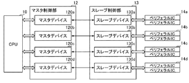
図1に示すように、本実施形態に係る情報処理装置1は、CPU10、マスタ制御部12、スレーブ制御部13、ペリフェラルIC14a〜14dを含む。CPU10は、情報処理装置1全体を制御する。また、CPU10は、マスタ制御部12内に含まれるマスタデバイス120a〜120dに対して制御信号を出力する。
As illustrated in FIG. 1, the
マスタ制御部12は、マスタデバイス120a〜120dを含む。以後の説明において、マスタデバイス120a〜120dを特に区別する必要がない場合には、「マスタデバイス120」と記載する。マスタデバイス120は、CPU10から入力された制御信号をシリアルデータに変換し、スレーブ制御部13に送信する。
The
スレーブ制御部13は、スレーブデバイス130a〜130dを含む。以後の説明において、スレーブデバイス130a〜130dを特に区別する必要がない場合には、「スレーブデバイス130」と記載する。スレーブデバイス130は、マスタデバイス120から受信したシリアルデータをパラレルデータに変換し、そのパラレルデータを制御信号としてペリフェラルIC14a〜14dに送信する。
The
また、スレーブデバイス130は、ペリフェラルIC14a〜14dから通知される割込み信号やリードアクセス時のリードデータをシリアルデータに変換し、マスタデバイス120に送信する。マスタデバイス120は、受信した割込み信号やリードアクセス時のリードデータをパラレルデータに変換し、CPU10に送信する。
In addition, the
尚、マスタデバイス120とスレーブデバイス130との間のシリアルバスとして、例えば、PCI Expressなどを用いてもよい。また、図1においては、ひとつのマスタデバイス120と、ひとつのスレーブデバイス130とがシリアル通信を行っている形態について説明を行っているが、スレーブデバイス130が複数接続されてシリアル通信を行う形態であってもよい。
As a serial bus between the
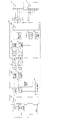
次に、図2を参照して、マスタデバイス120及びスレーブデバイス130の構成について説明する。図2は、本実施形態に係るマスタデバイス120及びスレーブデバイス130の構成を示す図である。図2に示すように、マスタデバイス120は、パラレルインタフェース(以後、「パラレルI/F」と記載する)102、パケット生成部121、8B/10B変換部122、シリアライザ123、デシリアライザ124、10B/8B変換部125、データ生成部103、通信異常検知部109、信号出力制御部110を含む。
Next, the configuration of the
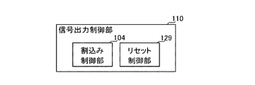
また、通信異常検知部109は、図3に示すように、パケット解析部126、エラー検知部127、タイミング生成部128を含む構成である。また、信号出力制御部110は、リセット制御部129、割込み制御部104を含む構成である。
As shown in FIG. 3, the communication
パラレルI/F102は、パラレルバスを介してCPU10からの制御信号を受信する。尚、図2に示すように、CPU10は、通信対象のペリフェラルIC14a1、14a2をそれぞれ示す信号であるチップセレクト信号(CS0_N、CS1_N)、アドレス(Addr)、ペリフェラルIC14にデータを書き込む動作(ライトアクセス)を行うことを示す信号(WE_N)、ペリフェラルIC14からデータを読み出す動作(リードアクセス)を行うことを示す信号(RE_N)、転送データ(DATA)をパラレルI/F102に出力する。
The parallel I /
尚、ライトアクセス時には、マスタデバイス120がデータを送信する送信部として、スレーブデバイス130がデータを受信する第一の受信部として機能する。また、リードアクセス時には、スレーブデバイス130がデータを送信する送信部として、マスタデバイス120がデータを受信する第一の受信部として機能する。
During write access, the
パケット生成部121は、CPU10から受信した転送データに、転送データの種類を示すヘッダなどを付加したパケットデータを生成するパケットデータ生成部である。8B/10B変換部122及びシリアライザ123は、パケット生成部121においてヘッダが付加された転送データをシリアルデータに変換し、シリアル通信を実行する。
The
尚、8B/10B変換部122は、データ長が8ビットの転送データをデータ長が10ビットの転送データに変換する。そして、シリアライザ123は、データ長が10ビットの転送データをパラレルデータからシリアルデータに変換してデシリアライザ134に送信する。すなわち、8B/10B変換部122はデータ長変換部として、シリアライザ123はパラレルシリアル変換部としてそれぞれ機能する。
The 8B /
デシリアライザ124及び10B/8B変換部125は、スレーブデバイス130から入力されたシリアルデータをパラレルデータに変換するシリアルパラレル変換部である。尚、デシリアライザ124は、データ長が10ビットの転送データを10B/8B変換部125に送信する。また、10B/8B変換部125は、データ長が10ビットの転送データをデータ長が8ビットの転送データに変換する。
The
パケット解析部126は、タイミング生成部128で生成されたタイミングにおいて、受信した転送データのパケットを解析し、その転送データがどのような種類のデータであるのかを確認する。この時、8B10B変換コード表において、受信したデータ長が10ビットの転送データに相当する8ビットのデータが存在しない場合がある。
The
これは、10ビットの組み合わせの方が8ビットの組み合わせよりも多いためである。したがって、パケット解析部126は、8B10B変換コード表において、受信したデータ長が10ビットの転送データに相当する8ビットのデータが存在しない場合に、データが受信できていないことをエラー検知部127に通知する。このように、パケット解析部126は、固有のパケットデータの受信状況に発生する特定の変化を検知する変化検知部として機能する。
This is because there are more 10-bit combinations than 8-bit combinations. Therefore, the
エラー検知部127は、パケット解析部126において固有のパケットデータが受信できなかった場合に、エラーカウントを1インクリメントする。また、エラー検知部127は、所定の回数以上連続してエラーカウントをインクリメントした場合に、マスタデバイス120とスレーブデバイス130との通信における異常の発生を検知したことを示す信号である、ERR_STATUS信号を出力する。
The
したがって、エラー検知部127は、パケット解析部126による検知結果に基づいてエラーカウントをインクリメントすることによって、マスタデバイス120とスレーブデバイス130との通信に発生した異常を検知する異常発生検知部として機能する。
Therefore, the
タイミング生成部128は、固有のパケットデータを受信するタイミングを生成する。尚、固有のパケットデータについて詳細は後述する。
The
リセット制御部129は、マスタデバイス120とスレーブデバイス130とのシリアル通信における異常が検知されると、マスタデバイス120とスレーブデバイス130とにリセット信号をアサートする。リセット制御部129は、マスタデバイス120及びスレーブデバイス130とハーネスによって接続される。
When an abnormality in the serial communication between the
また、マスタデバイス120とスレーブデバイス130においては、リセット信号がアサートされると、通信を再確立させる動作が実行される。したがって、エラー検知部127とリセット制御部129は、信号出力部として機能する。
Further, in the
データ生成部103は、受信したデータパケットに基づいて、パラレルデータを生成する。割込み制御部104は、スレーブデバイス130から受信した転送データに割込み信号が含まれる場合に、パラレルI/F102を介してCPU10に割込み信号を送信する。
The
また、図2に示すように、スレーブデバイス130は、パラレルI/F105、パケット生成部131、8B/10B変換部132、シリアライザ133、デシリアライザ134、10B/8B変換部135、割込み制御部106、通信異常検知部111を含む。
As shown in FIG. 2, the
通信異常検知部111は、図3に示した通信異常検知部109と同様の構成を持ち、パケット解析部136、エラー検知部137、タイミング生成部138を含む。
The communication abnormality detection unit 111 has the same configuration as the communication
パラレルI/F105は、ペリフェラルIC14a1、14a2のそれぞれからパラレルバスで信号を受信する。また、パラレルI/F105は、マスタデバイス120から受信したCPU10からの制御信号をペリフェラルIC14a1、14a2に送信する。
The parallel I /
尚、パケット生成部131はパケット生成部121と、8B/10B変換部132は8B/10B変換部122と、シリアライザ133はシリアライザ123と、デシリアライザ134はデシリアライザ124と、10B/8B変換部135は10B/8B変換部125と、エラー検知部137はエラー検知部127と、タイミング生成部138はタイミング生成部128と、それぞれ同様の動作を行うため、重複する説明を省略する。また、8B/10B変換部132はデータ長変換部として、シリアライザ133は送信制御部としてそれぞれ機能する。
The
パケット解析部136は、タイミング生成部138で生成されたタイミングにおいて、受信した転送データのパケットを解析し、その転送データがどのような種類のデータであるのかを確認する。更に、パケット解析部136は、8B10B変換コード表において、受信したデータ長が10ビットの転送データに相当する8ビットのデータが存在しない場合に、データが受信できていないことをエラー検知部137に通知する。
The
エラー検知部137は、パケット解析部136において固有のパケットデータが受信できなかった場合に、エラーカウントを1インクリメントする。また、エラー検知部137は、エラーカウントを所定以上連続してインクリメントした場合に、マスタデバイス120とスレーブデバイス130とのシリアル通信における異常の発生を検知したことを示す信号である、ERR_STATUS信号を出力する。
The error detection unit 137 increments the error count by 1 when the
したがって、エラー検知部137は、エラーカウントをインクリメントすることによって、マスタデバイス120とスレーブデバイス130との通信における異常状態を示す、通信異常計数部として機能する。
Therefore, the error detection unit 137 functions as a communication abnormality counting unit that indicates an abnormal state in communication between the
割込み制御部106は、ペリフェラルIC14a1、14a2から入力される割込み信号を割込みデータとしてパケット生成部131に入力する。また、割込み制御部106は、エラー検知部137からERR_STATUS信号が出力されると、マスタデバイス120とスレーブデバイス130とのシリアル通信における異常の発生を検知したことを示す割込みデータをパケット生成部131に入力する。
The interrupt
以上説明したような構成によって情報処理装置1は、マスタデバイス120とスレーブデバイス130との間でシリアル通信を行う。また、本実施形態においては、パケット生成部121及びパケット生成部131において、固有のパケットデータを生成し、シリアル通信における異常を検知する。以下、図面を参照して、パケット生成部121及びパケット生成部131で生成される固有のパケットデータについて説明する。
With the configuration described above, the
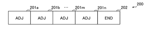
まず、マスタデバイス120からスレーブデバイス130に送信される固有のパケットデータについて説明する。図5は、マスタデバイス120からスレーブデバイス130に送信される固有のパケットデータであるデータ境界パケットデータ200を示す図である。データ境界パケットデータ200は、シリアルデータの境界位置がずれていないか確認するためにパケット生成部121で生成される固有のパケットデータである。
First, unique packet data transmitted from the
図5に示すように、データ境界パケットデータ200は、境界位置を確認するための基準となるデータであるADJパケット201a、・・・、201n(以後、それぞれを区別する必要がない場合には、「ADJパケット201」と記載する)、パケットデータの終点であることを示すENDパケット202を含む。
As shown in FIG. 5, the data
ADJパケット201は、マスタデバイス120からスレーブデバイス130へ繰り返し送信される。そのため、スレーブデバイス130でこのADJパケット201を受信した時にシリアルデータの境界位置がずれていないかを確認することができる。
The ADJ packet 201 is repeatedly transmitted from the
図6は、データ境界パケットデータ200が送信される際の送信間隔を示す図である。図6に示すように、マスタデバイス120からスレーブデバイス130との通信に異常が発生していない場合には、データ境界を調整するためのデータ境界パケットデータ200が定期的に送信される。したがって、このデータ境界パケットデータ200が定期的に受信されない場合には、マスタデバイス120とスレーブデバイス130との通信に異常が発生していることを検知することができる。
FIG. 6 is a diagram illustrating a transmission interval when the data
次に、スレーブデバイス130からマスタデバイス120に送信される固有のパケットデータについて説明する。図7は、スレーブデバイス130からマスタデバイス120にデータが送信される、いわゆる「リードアクセス時」にパケット生成部131で生成されるパケットデータであるリードパケットデータ300を示す図である。
Next, unique packet data transmitted from the
図7に示すように、リードパケットデータ300は、マスタデバイス120からのリードアクセスを受信したことを示すデータであるACSパケット301、リードデータであるRDATA302、パケットデータの終点であることを示すENDパケット303を含む。リードパケットデータ300は、リードアクセス時にスレーブデバイス130からリードデータを送信する時に、パケット生成部131によって生成される。スレーブデバイス130は、ACSパケット301の次にRDATA302を送信する。
As shown in FIG. 7, the read
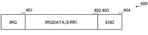
次に、スレーブデバイス130からマスタデバイス120に送信される割込みパケットデータ400について説明する。図8は、スレーブデバイス130からマスタデバイス120に送信される割込みパケットデータ400を示す図である。
Next, the interrupt
図8に示すように、割込みパケットデータ400は、割込み信号を受信したことを示すデータであるIRQパケット401、スレーブデバイス130に接続されているどのペリフェラルIC14aから割込み信号を受信したかを示すデータであるIRQDATA402、マスタデバイス120とスレーブデバイス130との通信に異常が検知されたことを示すデータであるERRパケット403、パケットデータの終点であることを示すENDパケット404を含む。
As shown in FIG. 8, the interrupt
パケット生成部131は、エラー検知部137によってERR_STATUS信号が出力された場合に、ERRパケット403を生成する。尚、ERRパケット403は、割込みパケットデータ400に含まれない構成であってもよい。
The
割込みパケットデータ400は、スレーブデバイス130に接続されるペリフェラルIC14aに異常が発生した場合に、スレーブデバイス130に割込み信号として入力される。また、スレーブデバイス130に接続されるペリフェラルIC14aに異常が発生したことをCPU10に通知するために、割込みパケットデータ400は、スレーブデバイス130からマスタデバイス120に送信される。
The interrupt
また、上述したように、割込みパケットデータ400には、ペリフェラルIC14aに関する情報の他に、スレーブデバイス130で検知されたマスタデバイス120とスレーブデバイス130との通信に発生している異常に関する情報を含む。したがって、マスタデバイス120は、この割込みパケットデータ400に含まれる情報に基づいてマスタデバイス120とスレーブデバイス130との通信に発生している異常を検知することができる。
Further, as described above, the interrupt
図9は、リードパケットデータ300、割込みパケットデータ400が送信される際の送信間隔を示す図である。図9に示すように、スレーブデバイス130からマスタデバイス120へは、定期的に割込みパケットデータ400が送信される。したがって、この割込みパケットデータ400を定期的に受信できない場合においても、マスタデバイス120とスレーブデバイス130との通信において異常が発生していることを検知することができる。
FIG. 9 is a diagram illustrating a transmission interval when the read
また、割込みパケットデータ400が送信されている途中にリードアクセスが発生した場合、パケット生成部131は、リードアクセスが発生したタイミングでリードパケットデータ300を生成し、送信する。この時、ランダムノイズなどの影響によって単発的な通信異常が発生した場合、マスタデバイス120がリードパケットデータ300を受信できないことがある。このような場合、マスタデバイス120とスレーブデバイス130との通信に発生している異常が一時的なものなのか、永続しているものなのかが判断できないことがある。
When a read access occurs while the interrupt
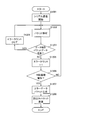
そこで、本実施形態においては、マスタデバイス120及びスレーブデバイス130の通信における異常の発生頻度に応じて、リセット信号を送信する。図10は、リードアクセス時におけるマスタデバイス120で行われるエラー検知を行う動作の流れをステップごとに示すフローチャートである。
Therefore, in the present embodiment, a reset signal is transmitted according to the frequency of occurrence of abnormality in communication between the
図10に示すように、マスタデバイス120とスレーブデバイス130とのシリアル通信が開始される(S1001)と、マスタデバイス120には、スレーブデバイス130から、図9に示すように、リードパケットデータ300が送信される。
As shown in FIG. 10, when serial communication between the
パケット解析部126は、スレーブデバイス130から受信したデータを構成するパケットの解析を実行する(S1002)。パケット解析部126は、スレーブデバイス130から受信したデータのヘッダの情報に基づいて、スレーブデバイス130から受信したデータにどのようなデータが含まれているかを解析した結果をエラー検知部127に送信する。
The
エラー検知部127はパケット解析部126が行った解析の結果に基づいて、ACSパケット301を受信したか否かを判定する(S1003)。スレーブデバイス130から受信したデータにACSパケット301が含まれている場合(S1003/YES)、エラー検知部127は、リードパケットデータ300を受信したと判断し、エラーカウントを初期化(クリア)し(S1004)、本処理を終了させる。
The
一方で、スレーブデバイス130から受信したデータにACSパケット301が含まれていない場合(S1003/NO)、ランダムノイズなどの影響によって単発的にエラーが発生したために、ACSパケット301が受信できない場合がある。そこで、エラー検知部127は、スレーブデバイス130から送信される割込みパケットデータ400の受信状況に基づいてマスタデバイス120とスレーブデバイス130との通信に発生した異常を検知する。
On the other hand, when the
図11は、マスタデバイス120において、割込みパケットデータ400の受信状況に基づいてマスタデバイス120とスレーブデバイス130との通信に発生した異常を検知する動作の流れをステップごとに示すフローチャートである。図11に示すように、マスタデバイス120とスレーブデバイス130とのシリアル通信が開始される(S1101)と、マスタデバイス120には、スレーブデバイス130から、図9に示すように、割込みパケットデータ400が定期的に送信される。
FIG. 11 is a flowchart showing an operation flow for each step in the
パケット解析部126は、スレーブデバイス130から受信したデータを構成するパケットを解析する(S1102)。この時、パケット解析部126は、スレーブデバイス130から受信したデータのヘッダの情報に基づいて、スレーブデバイス130から受信したデータにどのようなデータが含まれているかを解析した結果をエラー検知部127に送信する。
The
エラー検知部127は、パケット解析部126が行った解析の結果に基づいて、IRQパケット401を受信したか否かを判定する(S1103)。スレーブデバイス130から受信したデータにIRQパケット401が含まれている場合(S1103/YES)、エラー検知部127は、次にパケット解析部126から解析結果が送信されてくるまで待機する。
The
スレーブデバイス130から受信したデータにIRQパケット401が含まれていない場合(S1103/NO)、エラー検知部127は、エラーカウントを1インクリメントする(S1104)。そして、エラー検知部127は、エラーカウントが所定のN回以上連続してインクリメントされた場合(S1105/YES)、マスタデバイス120とスレーブデバイス130との間の通信経路に異常が発生していることを検知する。そしてエラー検知部127は、リセット制御部129にERR_STATUS信号を出力する。
When the
尚、この時、タイミング生成部128は、最初の割込みパケットデータ400が検知されてからカウントを開始する。スレーブデバイス130からは、割込みパケットデータ400が定期的に送信されているため、マスタデバイス120とスレーブデバイス130との通信に異常がない場合には、所定の間隔ごとに割込みパケットデータ400が送信されてくる。
At this time, the
本実施形態においてタイミング生成部128は、最初の割込みパケットデータ400が検知された時点から所定の間隔ごとにパケット解析部126にスレーブデバイス130から受信したデータを構成するパケットの解析を実行させる。したがって、所定のN回以上連続してエラーカウントがインクリメントされた場合に、エラー検知部127は、マスタデバイス120とスレーブデバイス130との間の通信経路に、単発的ではない異常が発生していると検知することができる。
In the present embodiment, the
リセット制御部129は、エラー検知部127から受信した制御信号に基づいて、マスタデバイス120とスレーブデバイス130との間にリセット信号をアサートする(S1106)。リセット信号がアサートされると、マスタデバイス120及びスレーブデバイス130は、通信を再確立させる動作が実行される。
The
このように、マスタデバイス120においては、マスタデバイス120が受信した割込みパケットデータ400に基づいて、マスタデバイス120とスレーブデバイス130との間の通信経路に発生した異常を検知する。
As described above, the
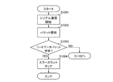
次に図面を参照して、マスタデバイス120からスレーブデバイス130にデータを書き込む動作であるライトアクセス時にエラーを検知する動作について説明する。図12は、ライトアクセス時にスレーブデバイス130がマスタデバイス120とスレーブデバイス130との通信に発生した異常の検知を行う動作の流れをステップごとに示すフローチャートである。
Next, an operation for detecting an error during a write access, which is an operation for writing data from the
図12に示すように、マスタデバイス120とスレーブデバイス130とのシリアル通信が開始される(S1201)と、スレーブデバイス130には、マスタデバイス120から、図6に示すように、データ境界パケットデータ200が送信される。
As shown in FIG. 12, when the serial communication between the
パケット解析部136は、マスタデバイス120から受信したデータを構成するパケットの解析を実行する(S1202)。パケット解析部136は、マスタデバイス120から受信したデータのヘッダの情報に基づいて、マスタデバイス120から受信したデータにどのようなデータが含まれているかを解析した結果をエラー検知部137に送信する。
The
エラー検知部137は、パケット解析部136が行った解析の結果に基づいて、ADJパケット201を受信したか否か判定する(S1203)。マスタデバイス120から受信したデータにADJパケット201が含まれている場合(S1203/YES)、エラー検知部137は、エラーカウントを初期化し(S1204)、次にパケット解析部136によってパケットの解析が実行されるまで待機する。
The error detection unit 137 determines whether or not the ADJ packet 201 has been received based on the result of the analysis performed by the packet analysis unit 136 (S1203). When the ADJ packet 201 is included in the data received from the master device 120 (S1203 / YES), the error detection unit 137 initializes the error count (S1204), and then the
マスタデバイス120から受信したデータにADJパケット201が含まれていない場合(S1203/NO)、エラー検知部137は、エラーカウントを1インクリメントする(S1205)。そして、エラー検知部137は、エラーカウントが所定のN回以上連続してインクリメントされた場合(S1206/YES)、マスタデバイス120とスレーブデバイス130との通信に異常が発生していることを検知する。
When the ADJ packet 201 is not included in the data received from the master device 120 (S1203 / NO), the error detection unit 137 increments the error count by 1 (S1205). Then, the error detection unit 137 detects that an abnormality has occurred in communication between the
エラー検知部137によって、マスタデバイス120とスレーブデバイス130との通信に異常が発生していることが検知されると、パケット生成部131は、ERRパケット403を生成し(S1207)、割込みパケットデータ400に挿入する。ERRパケット403が挿入された割込みパケットデータ400は、8B/10B変換部132及びシリアライザ133を介してマスタデバイス120に送信される(S1208)。
When the error detection unit 137 detects that an abnormality has occurred in communication between the
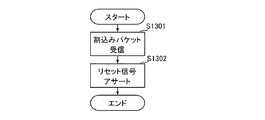
パケット解析部126は、割込みパケットデータ400を受信すると(S1301)、その割込みパケットデータ400にERRパケット403が含まれること示す情報をエラー検知部127に送信する。エラー検知部127は、ERRパケット403が含まれることを示す情報を受信すると、マスタデバイス120とスレーブデバイス130との通信に異常が発生していることを検知し、リセット制御部129にERR_STATUS信号を出力する。
When receiving the interrupt packet data 400 (S1301), the
リセット制御部129は、エラー検知部127から受信したERR_STATUS信号に基づいて、マスタデバイス120とスレーブデバイス130との間にリセット信号をアサートする(S1302)。リセット信号がアサートされると、マスタデバイス120及びスレーブデバイス130は、通信接続を再開させる動作を実行する。
The
尚、図12及び図13の説明においては、割込みパケットデータ400にERRパケット403が含まれていることを前提としている。しかし、マスタデバイス120とスレーブデバイス130との間の通信経路に異常が発生していない場合であって、かつ、ペリフェラルIC14a1、14a2に異常が発生していることがある。このような場合には、ERRパケット403が含まれない割込みパケットデータ400がマスタデバイス120に送信される。
In the description of FIGS. 12 and 13, it is assumed that the ERR packet 403 is included in the interrupt
このような場合、パケット解析部126は、受信した割込みパケットデータ400をデータ生成部103に送信する。データ生成部103は、受信した割込みパケットデータ400に基づいてパラレルデータを生成する。データ生成部103によって生成されたパラレルデータは、パラレルI/F102を介してCPU10に送信される。
In such a case, the
このように、マスタデバイス120が受信した割込みパケットデータ400に基づいて、マスタデバイス120とスレーブデバイス130との通信に発生した異常を検知することができる。尚、本実施形態に係る情報処理装置1において、マスタデバイス120とスレーブデバイス130とにおける情報の送受信方向、すなわち、リードアクセスもしくはライトアクセスに切り替える動作はCPU10によって行われる。
Thus, based on the interrupt
上述したように、本実施形態においては、マスタデバイス120とスレーブデバイス130との通信に異常が発生していることを検知するための固有のパケットデータを転送データに含める。このようにすることで、リードアクセス時及びライトアクセス時どちらであっても、マスタデバイス120とスレーブデバイス130との通信に異常が発生していることを検知して、通信異常を検知した際には通信を再確立させることができる。
As described above, in the present embodiment, unique packet data for detecting that an abnormality has occurred in communication between the
また、エラー検知部127、137がそれぞれマスタデバイス120及びスレーブデバイス130の通信に異常が発生していること検知して、通信を再開させることが可能となる。
Further, the
更に、マスタデバイス120とスレーブデバイス130との通信の異常が頻発している場合、固有のパケットデータの送信間隔を短くし、CPU10に異常が検知されたことを早期に通知する必要がある。そのために、図14に示すように、固有のパケットデータの送信間隔の設定値が保存される定期送信間隔設定レジスタ151、152を含む構成であってもよい。
Further, when communication abnormality between the
図14に示すように、定期送信間隔設定レジスタ151は、マスタデバイス120のパケット生成部121から8B/10B変換部122に転送データを送信する際の送信間隔が記憶されている。そのため、CPU10は、割込みパケットデータ400の受信状況に応じて定期送信間隔設定レジスタ151に記憶されている送信間隔が変動するように設定することが可能である設定部として機能する。
As illustrated in FIG. 14, the regular transmission
また、定期送信間隔設定レジスタ152は、スレーブデバイス130のパケット生成部131から8B/10B変換部132に転送データを送信する際の送信間隔が記憶されている。定期送信間隔設定レジスタ152は、ペリフェラルIC14aから入力される割込み信号の頻度によって設定される構成であってもよい。したがって、定期送信間隔設定レジスタ151、152は、記憶部として機能する。
Further, the regular transmission
このように、マスタデバイス120及びスレーブデバイス130から送信される固有のパケットデータの送信間隔を変更して、CPU10に対して通信異常が検知されたことを早期に送信することができる。
In this way, it is possible to change the transmission interval of the unique packet data transmitted from the
また、図15に示すように、定期送信間隔設定レジスタ151、152の代わりにメモリ153、154を用いる構成であってもよい。このような場合、異常が発生する頻度に応じてパケット生成部121、131がメモリ153、154にそれぞれアクセスすることで、固有のパケットデータの送信間隔を、CPU10を介在させることなく変更することが可能になる。
Further, as shown in FIG. 15, a
メモリ153、154は、シリアル通信を開始する以前にCPU10によって固有のパケットデータの送信間隔が書き込まれて保存されていてもよい。このような場合、シリアル通信が開始されている間にマスタデバイス120からCPU10にアクセスする必要がないため、CPU10の処理負荷を低減させることができる。そのため、メモリ153、154も、送信間隔設定情報記憶部として機能する。
The
実施の形態2.
実施の形態1において、リセット制御部129は、マスタデバイス120及びスレーブデバイス130とハーネスによって接続されている。しかし、情報処理装置1を構成する回路基板のレイアウトや配線によっては、ハーネスで接続することが困難な場合がある。
In the first embodiment, the
そこで、本実施形態では、図16に示すように、エラー検知部127によってシリアル通信に異常が検知された場合に、8B/10B変換部122及びシリアライザ123を介してスレーブデバイス130にリセット信号を入力する。このような構成によって、本実施形態においては、不要なハーネスを設置することなくマスタデバイス120及びスレーブデバイス130をリセットすることができる。
Therefore, in this embodiment, as shown in FIG. 16, when an error is detected in the serial communication by the
実施の形態3.
図17は、スレーブデバイス130にリセット制御部139が含まれる情報処理装置1の構成を示す図である。図17に示すように、リセット制御部139は、エラー検知部137からERR_STATUS信号を受信するとマスタデバイス120に対してリセット信号をアサートする。本実施形態に係る情報処理装置1においては、マスタデバイス120で通信異常が検知された場合は、実施の形態1で説明したように、リセット制御部129によってリセット信号がアサートされる。
FIG. 17 is a diagram illustrating a configuration of the
尚、リセット端子4は、双方向端子であり、図17に示すように抵抗器5を挟んで設置され、リセット制御部129、139によってリセット端子4の電位が制御される。リセット制御部129によって、リセット端子4の電位がL(低電位、Low)に制御されると、スレーブデバイス130に対してリセット信号がアサートされる。
The reset terminal 4 is a bidirectional terminal, and is installed with the resistor 5 interposed therebetween as shown in FIG. 17, and the potential of the reset terminal 4 is controlled by the
また、リセット制御部139によって、リセット端子4の電位がLに制御されると、マスタデバイス120に対してリセット信号がアサートされる。このように本実施形態においては、スレーブデバイス130でマスタデバイス120とスレーブデバイス130との通信に異常が検知された場合に、マスタデバイス120に通知せずとも通信を再確立することができる。
In addition, when the
実施の形態4.
複合機等の情報処理装置1においては、CPU10によって制御されるDMAC(Direct Memory Access Controler)をマスタデバイス120として、プリンタやFAXの動作を制御するプリンタ制御部やFAX制御部がスレーブデバイス130として構成されることがある。そして、これらのプリンタ制御部やFAX制御部から転送されるデータが記憶されるメモリ等の記憶媒体へのアクセスを制御するメモリコントローラが含まれることもある。
Embodiment 4 FIG.
In the
このような場合、メモリコントローラは、図18に示すように、スレーブデバイス130であるプリンタ制御部やFAX制御部とシリアル通信を行うスレーブデバイス130cとして構成される。したがって、メモリコントローラは、スレーブデバイス130から送信されるシリアルデータの転送先となる第二の受信部であるスレーブデバイス130cとして機能する。
In such a case, as shown in FIG. 18, the memory controller is configured as a
図18に示すように、スレーブデバイス130に対してスレーブデバイス130cが接続される構成が含まれる情報処理装置1においては、スレーブデバイス130とスレーブデバイス130cとの間に通信異常が発生することがある。そこで、本実施形態においては、スレーブデバイス130とスレーブデバイス130cとの間の通信異常が検知された場合に、スレーブデバイス130及びスレーブデバイス130cがリセットされるように制御する。
As illustrated in FIG. 18, in the
図18に示すように、スレーブデバイス130は、図2に示した構成に加えて、パケット生成部131b、8B/10B変換部132b、シリアライザ133b、デシリアライザ134b、10B/8B変換部135b、通信異常検知部111b、リセット制御部139を含む。
As shown in FIG. 18, in addition to the configuration shown in FIG. 2, the
また、スレーブデバイス130cは、パラレルI/F107、パケット生成部131c、8B/10B変換部132c、シリアライザ133c、デシリアライザ134c、10B/8B変換部135c、割込み制御部108、通信異常検知部111cを含む。
The
スレーブデバイス130cにおいて行われるスレーブデバイス130とスレーブデバイス130cとの通信に発生した異常の検知は、図12で説明した動作と同様の動作をスレーブデバイス130cが行うため、重複する説明を省略する。
Detection of an abnormality occurring in communication between the
尚、パケット生成部131b、cはパケット生成部131と、8B/10B変換部132b、cは8B/10B変換部132と、シリアライザ133b、cはシリアライザ133と、デシリアライザ134b、cはデシリアライザ134と、10B/8B変換部135b、cは10B/8B変換部135と、エラー検知部137b、cはエラー検知部137と、タイミング生成部138b、cはタイミング生成部138と、それぞれ同様の動作を行うため、重複する説明を省略する。
The packet generators 131b and c are the
また、パケット解析部136b、cは、スレーブデバイス130から受信した転送データのパケットを解析し、その転送データがどのような種類のデータであるのかを確認する。更に、パケット解析部136b、cは、受信したデータ長が10ビットの転送データが、8B10B変換コード表に対して当てはまらない場合、スレーブデバイス130からの転送データが受信できていないことをそれぞれエラー検知部137b、cに通知する。
Further, the packet analysis units 136b and 136c analyze the transfer data packet received from the
図19は、スレーブデバイス130cからシリアル通信に発生した異常を検知するERRパケット403を含む割込みパケットデータ400を受信したスレーブデバイス130の動作の流れをステップごとに示すフローチャートである。図19に示すように、パケット解析部136bは、ERRパケット403を含む割込みパケットデータ400を受信する(S1901)と、ERRパケット403を受信したことをエラー検知部137bに通知する。
FIG. 19 is a flowchart showing, for each step, the operation flow of the
エラー検知部137bは、パケット解析部136からERRパケット403を受信したことを示す通知を受けると、ERR_STATUS信号をリセット制御部139及びパケット生成部131に対して出力する(S1902)。
Upon receiving a notification indicating that the ERR packet 403 has been received from the
パケット生成部131は、ERR_STATUS信号を受信すると、ERRパケット403を生成し、割込みパケットデータ400として8B/10B変換部132及びシリアライザ133を介してマスタデバイス120に送信する(S1903)。
Upon receiving the ERR_STATUS signal, the
スレーブデバイス130からERRパケット403を含む割込みパケットデータ400を受信したマスタデバイス120の動作は、図13で説明した動作と同様の動作を行うため、説明を省略する。尚、リセット制御部129から、リセット制御部139及びリセット制御部139cに対してリセット信号を出力する。
The operation of the
次に、マスタデバイス120から送信されたリセット信号を受信したスレーブデバイス130、130cの動作について、図20を参照して説明する。図20は、スレーブデバイス130、130cがリセット動作を実施する際の流れをステップごとに示すフローチャートである。尚、図20においては、スレーブデバイス130について説明するが、スレーブデバイス130cにおいても、同様の動作を行う。
Next, operations of the
リセット制御部139は、ERR_STATUS信号を受信している場合(S2001/Yes)にマスタデバイス120からリセット信号を受信する(S2002)と、スレーブデバイス130に対してリセット動作を実行する(S2003)。リセットされたスレーブデバイス130においては、シリアル通信を再確立させる動作が実行される(S2004)。
When the
このように、スレーブデバイス130、130cは、エラー検知部137b、137cが生成したERR_STATUS信号及びマスタデバイス120から入力されたリセット信号のいずれもが検知された場合にリセット動作を実行する。そのため、マスタデバイス120から、同時にリセット信号が送信された場合であってもERR_STATUS信号が検知されない場合には、スレーブデバイス130、130cはリセット動作を行わない。
As described above, the
そのため、例えば、マスタデバイス120とスレーブデバイス130との間の通信に異常が発生している場合には、リセット信号が入力されてもスレーブデバイス130cは、ERR_STATUS信号が出力されていないため、リセット動作を行わない。
Therefore, for example, when an abnormality occurs in communication between the
また、図21に示すように、スレーブデバイス130にリセット制御部139bを設置することもできる。このような場合、スレーブデバイス130同士の通信に異常が検知された際に、マスタデバイス120にERR_STATUS信号を送信せずともスレーブデバイス130とスレーブデバイス130cとの通信を再確立させることができる。
Further, as shown in FIG. 21, a reset control unit 139 b can be installed in the
したがって、実施の形態4に係る情報処理装置1においてシリアル通信経路における異常が発生した場合には、異常が発生しているシリアル通信経路にのみリセット動作を実行することができる。
Therefore, when an abnormality occurs in the serial communication path in the
尚、以上説明した全ての実施の形態において、定期的に送信される固有のパケットデータは、情報処理装置1が動作する際の周波数によって決まる。この時、例えば、情報処理装置1が動作する際の周波数が100MHzであった場合、固有のパケットデータが連続二回検出されない時には、およそ25μ秒でリセット信号が出力される。
In all the embodiments described above, the unique packet data transmitted periodically is determined by the frequency at which the
また、以上説明した全ての実施の形態においては、8B/10B方式のシリアル高速通信を行う情報処理装置を例として説明を行ったが、PCI Express 3.0で採用されている128B/130B方式においても、上記実施の形態と同様の効果をえることが出来る。 In all the embodiments described above, the information processing apparatus that performs the serial high-speed communication of the 8B / 10B system has been described as an example. However, in the 128B / 130B system adopted in the PCI Express 3.0, Also, the same effect as the above embodiment can be obtained.
1 情報処理システム
4 リセット端子
5 抵抗器
10 CPU
12 マスタ制御部
13 スレーブ制御部
14 ペリフェラルIC
102 パラレルI/F
103 データ生成部
104、106、108 割込み制御部
120 マスタデバイス
121、131 パケット生成部
122、132 8B/10B変換部
123、133 シリアライザ
124、134 デシリアライザ
125、135 10B/8B変換部
126、136 パケット解析部
127、137 エラー検知部
128、138 タイミング生成部
129、139 リセット制御部
130 スレーブデバイス
200 データ境界パケットデータ
300 リードパケットデータ
400 割込みパケットデータ
1 Information Processing System 4 Reset Terminal 5
12
102 Parallel I / F
103
Claims (10)
前記パラレルシリアル変換部と前記シリアルパラレル変換部との間で所定の間隔ごとに送受信される固有のパケットデータを生成するパケットデータ生成部と、
前記パラレルシリアル変換部から前記シリアルパラレル変換部に送信された前記固有のパケットデータの前記シリアルパラレル変換部における受信状況に特定の変化が発生したことを検知する変化検知部と、
前記特定の変化の検知結果に基づいて、前記パラレルシリアル変換部と前記シリアルパラレル変換部との通信経路に異常が発生していることを検知する異常発生検知部と、
前記異常が発生していることが検知された場合に、前記パラレルシリアル変換部と前記シリアルパラレル変換部との間の通信を再確立させるための制御信号を出力する信号出力部と、
を含むことを特徴とする情報処理装置。 Serial communication between a parallel-serial conversion unit that converts parallel data into serial data and transmits the serial data transmitted from the parallel-serial conversion unit and converts the serial data into the parallel data. An information processing apparatus for performing
A packet data generation unit that generates unique packet data transmitted and received at predetermined intervals between the parallel-serial conversion unit and the serial-parallel conversion unit;
A change detection unit that detects that a specific change has occurred in the reception status of the unique packet data transmitted from the parallel-serial conversion unit to the serial-parallel conversion unit in the serial-parallel conversion unit;
Based on the detection result of the specific change, an abnormality occurrence detection unit that detects that an abnormality has occurred in a communication path between the parallel-serial conversion unit and the serial-parallel conversion unit;
A signal output unit that outputs a control signal for re-establishing communication between the parallel-serial conversion unit and the serial-parallel conversion unit when it is detected that the abnormality has occurred;
An information processing apparatus comprising:
所定の回数以上連続して前記特定の変化を検知した場合に、前記異常が発生していることを検知することを特徴とする請求項1に記載の情報処理装置。 The abnormality occurrence detection unit
The information processing apparatus according to claim 1, wherein the abnormality is detected when the specific change is detected continuously for a predetermined number of times or more.
前記パラレルシリアル変換部は、
前記データ長が変換された固有のパケットデータを前記シリアルパラレル変換部に送信し、
前記変化検知部は、
前記所定の間隔ごとに前記データ長が変換される前と前記データ長が変換された後とにおける前記固有のパケットデータが、前記変換コード表に当てはまらない場合に、前記特定の変化を検知することを特徴とする請求項1又は2に記載の情報処理装置。 A data length conversion unit for converting the data length of the unique packet data based on a conversion code table for converting the data length;
The parallel serial converter is
Transmit the unique packet data converted in data length to the serial-parallel converter,
The change detector is
Detecting the specific change when the unique packet data before and after the data length is converted at each predetermined interval does not apply to the conversion code table. The information processing apparatus according to claim 1 or 2.
前記制御信号を、前記通信経路を介して出力することを特徴とする請求項1ないし3いずれか1項に記載の情報処理装置。 The signal output unit is
The information processing apparatus according to claim 1, wherein the control signal is output via the communication path.
前記シリアルパラレル変換部を含む受信部と、
を含み、
前記送信部と前記受信部とはそれぞれ前記信号出力部を含むことを特徴とする請求項1ないし4いずれか1項に記載の情報処理装置。 A transmission unit including the parallel-serial conversion unit;
A receiver including the serial-parallel converter;
Including
The information processing apparatus according to claim 1, wherein each of the transmission unit and the reception unit includes the signal output unit.
設定された前記所定の間隔を記憶する記憶部と、
を含むことを特徴とする請求項1ないし5いずれか1項に記載の情報処理装置。 A setting unit that sets the predetermined interval based on the reception status of the unique packet data;
A storage unit for storing the set predetermined interval;
The information processing apparatus according to any one of claims 1 to 5, further comprising:
前記送信部に含まれるパラレルシリアル変換部から送信された前記シリアルデータを受信して前記パラレルデータに変換するシリアルパラレル変換部と、変換された前記パラレルデータをシリアルデータに変換して送信するパラレルシリアル変換部と、を含む第一の受信部と、
前記第一の受信部に含まれる前記パラレルシリアル変換部から送信された前記シリアルデータを受信して前記パラレルデータに変換するシリアルパラレル変換部を含む第二の受信部と、
を含み、
前記パケットデータ生成部は、
前記第一の受信部に含まれるパラレルシリアル変換部と前記第二の受信部に含まれるシリアルパラレルとの間で所定の間隔ごとに送受信される固有のパケットデータを生成し、
前記変化検知部は、
前記第一の受信部に含まれる前記パラレルシリアル変換部から前記第二の受信部に含まれる前記シリアルパラレル変換部に送信された前記固有のパケットデータの前記第二の受信部に含まれる前記シリアルパラレル変換部における受信状況に特定の変化が発生したことを検知し、
前記異常発生検知部は、
前記第二の受信部に含まれる前記シリアルパラレル変換部における受信状況に発生した前記特定の変化の検知結果に基づいて、前記第一の受信部に含まれる前記パラレルシリアル変換部と前記第二の受信部に含まれる前記シリアルパラレル変換部との通信経路に異常が発生していることを検知し、
前記信号出力部は、
前記異常が発生していることが検知された場合に、前記パラレルシリアル変換部と前記第二の受信部に含まれる前記シリアルパラレル変換部との間の通信を再確立させるための制御信号を出力することを特徴とする請求項1乃至6いずれか1項に記載の情報処理装置。 A transmission unit including the parallel-serial conversion unit;
A serial-parallel converter that receives the serial data transmitted from the parallel-serial converter included in the transmitter and converts the serial data into the parallel data; and a parallel serial that converts the converted parallel data into serial data and transmits the serial data A first receiving unit including a conversion unit;
A second receiving unit including a serial-parallel conversion unit that receives the serial data transmitted from the parallel-serial conversion unit included in the first receiving unit and converts the serial data into the parallel data;
Including
The packet data generation unit
Generate unique packet data to be transmitted and received at predetermined intervals between the parallel-serial conversion unit included in the first reception unit and the serial-parallel included in the second reception unit,
The change detector is
The serial included in the second receiver of the unique packet data transmitted from the parallel-serial converter included in the first receiver to the serial-parallel converter included in the second receiver Detect that a specific change has occurred in the reception status in the parallel converter,
The abnormality occurrence detection unit
Based on the detection result of the specific change occurring in the reception status in the serial-parallel converter included in the second receiver, the parallel-serial converter included in the first receiver and the second Detecting that an abnormality has occurred in the communication path with the serial-parallel converter included in the receiver,
The signal output unit is
When it is detected that the abnormality has occurred, a control signal for re-establishing communication between the parallel-serial conversion unit and the serial-parallel conversion unit included in the second reception unit is output. The information processing apparatus according to claim 1, wherein the information processing apparatus is an information processing apparatus.
前記第一の受信部に含まれる前記信号出力部は、
前記第一の受信部に含まれる前記パラレルシリアル変換部と前記第二の受信部に含まれる前記シリアルパラレル変換部との通信経路に異常が発生していることを検知された場合に、前記第一の受信部に含まれる前記パラレルシリアル変換部と前記第二の受信部に含まれる前記シリアルパラレル変換部との間の通信を再確立させるための制御信号を出力することを特徴とする請求項7に記載の情報処理装置。 The first receiving unit includes the signal output unit,
The signal output unit included in the first receiving unit is:
When it is detected that an abnormality has occurred in a communication path between the parallel-serial conversion unit included in the first reception unit and the serial-parallel conversion unit included in the second reception unit, the first The control signal for re-establishing communication between the parallel-serial conversion unit included in one receiving unit and the serial-parallel conversion unit included in the second receiving unit is output. 8. The information processing apparatus according to 7.
前記パラレルシリアル変換部と前記シリアルパラレル変換部との間で所定の間隔ごとに送受信される固有のパケットデータを生成し、
前記パラレルシリアル変換部から前記シリアルパラレル変換部に送信された前記固有のパケットデータの前記シリアルパラレル変換部における受信状況に特定の変化が発生したことを検知し、
前記特定の変化の検知結果に基づいて、前記パラレルシリアル変換部と前記シリアルパラレル変換部との通信経路に異常が発生していることを検知し、
前記異常が発生していることが検知された場合に、前記パラレルシリアル変換部と前記シリアルパラレル変換部との間の通信を再確立させるための制御信号を出力することを特徴とするシリアル通信方法。 Serial communication between a parallel-serial conversion unit that converts parallel data to serial data and transmits the serial data transmitted from the parallel-serial conversion unit and converts the serial data into the parallel data. A serial communication method for controlling,
Generate unique packet data transmitted and received at predetermined intervals between the parallel-serial converter and the serial-parallel converter,
Detecting that a specific change has occurred in the reception status in the serial-parallel converter of the unique packet data transmitted from the parallel-serial converter to the serial-parallel converter,
Based on the detection result of the specific change, it is detected that an abnormality has occurred in the communication path between the parallel-serial conversion unit and the serial-parallel conversion unit,
A serial communication method characterized by outputting a control signal for re-establishing communication between the parallel-serial conversion unit and the serial-parallel conversion unit when it is detected that the abnormality has occurred .
前記パラレルシリアル変換部と前記シリアルパラレル変換部との間で所定の間隔ごとに送受信される固有のパケットデータを生成するステップと、
前記パラレルシリアル変換部から前記シリアルパラレル変換部に送信された前記固有のパケットデータの前記シリアルパラレル変換部における受信状況に特定の変化が発生したことを検知するステップと、
前記特定の変化の検知結果に基づいて、前記パラレルシリアル変換部と前記シリアルパラレル変換部との通信経路に異常が発生していることを検知するステップと、
前記異常が発生していることが検知された場合に、前記パラレルシリアル変換部と前記シリアルパラレル変換部との間の通信を再確立させるための制御信号を出力するステップとを、
実行させることを特徴とするシリアル通信プログラム。 Serial communication between a parallel-serial conversion unit that converts parallel data to serial data and transmits the serial data transmitted from the parallel-serial conversion unit and converts the serial data into the parallel data. A serial communication program to control,
Generating unique packet data transmitted and received at predetermined intervals between the parallel-serial conversion unit and the serial-parallel conversion unit;
Detecting that a specific change has occurred in the reception status of the unique packet data transmitted from the parallel-serial conversion unit to the serial-parallel conversion unit in the serial-parallel conversion unit;
Based on the detection result of the specific change, detecting that an abnormality has occurred in the communication path between the parallel-serial conversion unit and the serial-parallel conversion unit;
A step of outputting a control signal for re-establishing communication between the parallel-serial conversion unit and the serial-parallel conversion unit when it is detected that the abnormality has occurred;
A serial communication program characterized by being executed.
Priority Applications (1)
| Application Number | Priority Date | Filing Date | Title |
|---|---|---|---|
| JP2016085313A JP2017195534A (en) | 2016-04-21 | 2016-04-21 | Information processing apparatus, serial communication method, and serial communication program |
Applications Claiming Priority (1)
| Application Number | Priority Date | Filing Date | Title |
|---|---|---|---|
| JP2016085313A JP2017195534A (en) | 2016-04-21 | 2016-04-21 | Information processing apparatus, serial communication method, and serial communication program |
Publications (1)
| Publication Number | Publication Date |
|---|---|
| JP2017195534A true JP2017195534A (en) | 2017-10-26 |
Family
ID=60156145
Family Applications (1)
| Application Number | Title | Priority Date | Filing Date |
|---|---|---|---|
| JP2016085313A Pending JP2017195534A (en) | 2016-04-21 | 2016-04-21 | Information processing apparatus, serial communication method, and serial communication program |
Country Status (1)
| Country | Link |
|---|---|
| JP (1) | JP2017195534A (en) |
Cited By (3)
| Publication number | Priority date | Publication date | Assignee | Title |
|---|---|---|---|---|
| JP2018092593A (en) * | 2016-11-30 | 2018-06-14 | 株式会社リコー | Information processing apparatus and program |
| JP2019165433A (en) * | 2018-03-14 | 2019-09-26 | ローム株式会社 | Bidirectional transmission system, serializer circuit, deserializer circuit, and automobile |
| CN114760409A (en) * | 2021-11-24 | 2022-07-15 | 广州汽车集团股份有限公司 | Vehicle camera control method and device |
-
2016
- 2016-04-21 JP JP2016085313A patent/JP2017195534A/en active Pending
Cited By (4)
| Publication number | Priority date | Publication date | Assignee | Title |
|---|---|---|---|---|
| JP2018092593A (en) * | 2016-11-30 | 2018-06-14 | 株式会社リコー | Information processing apparatus and program |
| JP6996166B2 (en) | 2016-11-30 | 2022-01-17 | 株式会社リコー | Information processing equipment and programs |
| JP2019165433A (en) * | 2018-03-14 | 2019-09-26 | ローム株式会社 | Bidirectional transmission system, serializer circuit, deserializer circuit, and automobile |
| CN114760409A (en) * | 2021-11-24 | 2022-07-15 | 广州汽车集团股份有限公司 | Vehicle camera control method and device |
Similar Documents
| Publication | Publication Date | Title |
|---|---|---|
| KR20180066049A (en) | COMMUNICATION DEVICE, COMMUNICATION METHOD, PROGRAM, AND COMMUNICATION SYSTEM | |
| KR20190134480A (en) | Error checking for primary signal transmitted between first and second clock domains | |
| US9001950B2 (en) | Information processing apparatus, serial communication system, method of initialization of communication therefor, and serial communication apparatus | |
| JP2017195534A (en) | Information processing apparatus, serial communication method, and serial communication program | |
| US9201623B2 (en) | Control device and image forming apparatus with two controllers | |
| JP3740483B2 (en) | Electronic device and method for diagnosing abnormality thereof | |
| JP6136754B2 (en) | Communication control apparatus and image forming apparatus | |
| JPH08123770A (en) | Data communication controller | |
| US9081743B2 (en) | Communication system and communicaton method | |
| WO2022124083A1 (en) | Communication device, communication method, and program | |
| JP5082147B2 (en) | Multi-node system, inter-node switch, and data relay method | |
| KR100737904B1 (en) | Interface device between master / slave device and method | |
| JP6171367B2 (en) | Switch device, image processing device, and exclusive control method | |
| JP3784624B2 (en) | Communication direction switching method | |
| JP5920370B2 (en) | Electronic control unit | |
| JP5482306B2 (en) | Data transfer control device and electronic device | |
| JP6163941B2 (en) | Control device and image forming apparatus | |
| JP6213003B2 (en) | Communication control device, image processing device, communication control program | |
| CN120429250A (en) | Data transmission method, device and chip | |
| JP6107499B2 (en) | Communication control apparatus and image forming apparatus | |
| JP4624252B2 (en) | Data packet transfer device, data packet transfer method, and data packet transfer program | |
| JP5202787B2 (en) | Supervisory control device | |
| JP6217206B2 (en) | Communication control device, image processing device, transfer control program | |
| KR20210045198A (en) | Device and driving method thereof of DDS data conversion and transmission | |
| KR20210045196A (en) | Device of DDS data conversion and transmission |