JP2017195730A - motor - Google Patents
motor Download PDFInfo
- Publication number
- JP2017195730A JP2017195730A JP2016085729A JP2016085729A JP2017195730A JP 2017195730 A JP2017195730 A JP 2017195730A JP 2016085729 A JP2016085729 A JP 2016085729A JP 2016085729 A JP2016085729 A JP 2016085729A JP 2017195730 A JP2017195730 A JP 2017195730A
- Authority
- JP
- Japan
- Prior art keywords
- motor
- space
- hole
- sound
- motor unit
- Prior art date
- Legal status (The legal status is an assumption and is not a legal conclusion. Google has not performed a legal analysis and makes no representation as to the accuracy of the status listed.)
- Pending
Links
Images
Landscapes
- Motor Or Generator Frames (AREA)
Abstract
【課題】モータ部から発生する騒音を低減することができるモータを提供する。【解決手段】円筒状のハウジング210内にロータおよびステータが設けられたモータ部200と、モータ部200を収容する円筒状のモータカバー300とを備えたモータ100であって、モータカバー300の内部に、該内部を内周側の空間350と外周側の空間360とに仕切る円筒状の壁部340を設け、モータ部200を内周側の空間350に収容し、壁部340に、内周側の空間350と外周側の空間360とを連通する複数の孔341を形成し、外周側の空間360と孔341とによって、モータ部200から発生する音波の所定周波数を減衰させる吸音器370を構成する。【選択図】図2A motor capable of reducing noise generated from a motor unit is provided. A motor 100 includes a motor part 200 in which a rotor and a stator are provided in a cylindrical housing 210, and a cylindrical motor cover 300 that accommodates the motor part 200. A cylindrical wall portion 340 that divides the interior into an inner space 350 and an outer space 360, and the motor unit 200 is accommodated in the inner space 350. A plurality of holes 341 that communicate with the outer space 350 and the outer space 360 are formed, and the sound absorber 370 that attenuates a predetermined frequency of sound waves generated from the motor unit 200 is formed by the outer space 360 and the holes 341. Configure. [Selection] Figure 2
Description
本発明はモータに係り、特に騒音を低減することができる構造を有するモータに関する。 The present invention relates to a motor, and more particularly to a motor having a structure capable of reducing noise.
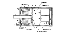
特許文献1により、モータ部から発生する騒音を簡単な構成により減衰させるようにしたモータが知られている。同文献に記載の制御ユニット付きモータは、図5に示すように、モータフレーム2と制御ケース9との間に軸受ブラケット2cを設け、軸受ブラケット2cに設けた孔15を介して音発生源であるモータ部1内と制御ケース9内とを連通しており、制御ケース9内の空間と孔15によって消音器16が構成されている。そして、制御ケース9の三辺の長さ寸法Lx、Ly、Lzを、モータ部1から発生する音波の半波長の整数倍または1/整数倍と一致しないように設定することで、制御ケース9からの放射騒音の低減を図っている。
Patent Document 1 discloses a motor in which noise generated from a motor unit is attenuated with a simple configuration. As shown in FIG. 5, the motor with a control unit described in this document is provided with a
特許文献1に記載のモータは、モータ部1から発生した音波が軸受ブラケット2cに設けた孔15から消音器16に伝搬されて騒音が減衰されるが、モータ部1から発生した音波がモータフレーム2から放射される場合、その騒音を低減することができる構成とはなっていない。
In the motor described in Patent Document 1, the sound wave generated from the motor unit 1 is propagated to the silencer 16 from the
本発明は上記事情に鑑みてなされたものであり、モータ部から発生する騒音を低減することができるモータを提供することを目的とする。 This invention is made | formed in view of the said situation, and it aims at providing the motor which can reduce the noise which generate | occur | produces from a motor part.
本発明のモータは、円筒状のハウジング内にロータおよびステータが設けられたモータ部と、前記モータ部を収容する円筒状のモータカバーと、を備えたモータであって、前記モータカバーの内部には、該内部を内周側の空間と外周側の空間とに仕切る円筒状の壁部が設けられ、前記モータ部は前記内周側の空間に収容され、前記壁部には前記内周側の空間と前記外周側の空間とを連通する孔が形成され、前記外周側の空間と前記孔とによって、前記モータ部から発生する音波の所定周波数を減衰させる吸音器が構成されることを特徴とする。 A motor according to the present invention is a motor including a motor unit in which a rotor and a stator are provided in a cylindrical housing, and a cylindrical motor cover that accommodates the motor unit, and the motor cover is provided inside the motor cover. Is provided with a cylindrical wall portion that divides the interior into a space on the inner peripheral side and a space on the outer peripheral side, the motor portion is accommodated in the space on the inner peripheral side, and the wall portion includes the inner peripheral side. A hole for communicating the outer space and the outer space is formed, and the outer space and the hole constitute a sound absorber that attenuates a predetermined frequency of sound waves generated from the motor unit. And
本発明によれば、上記吸音器によって次のようにモータ部から発生する音が低減する。モータ部の音はハウジングから放射し、その音は、モータカバーの壁部の孔内の空気を音圧加振する。すると、孔内の空気が質量、外周側の空間の空気層がばねとなる振動現象が起こり、孔内の空気と、孔の外周側の表面との間にせん断摩擦が起こって音のエネルギーが熱エネルギーに変換する。また、孔内では空気が振動することで渦が発生して摩擦が生じ、これにより音のエネルギーが熱エネルギーに変換する。これらの音のエネルギーが熱エネルギーに変換する作用により、モータ部から発生する音は減衰し、結果として騒音が低減する。 According to the present invention, the sound generated from the motor unit is reduced by the sound absorber as follows. The sound of the motor part is radiated from the housing, and the sound excites the air in the hole of the wall part of the motor cover with sound pressure. As a result, a vibration phenomenon occurs in which the air in the hole has a mass and the air layer in the outer peripheral space acts as a spring, and shear friction occurs between the air in the hole and the outer peripheral surface of the hole, and sound energy is generated. Convert to heat energy. In addition, air oscillates in the hole to generate vortices and friction, thereby converting sound energy into heat energy. Due to the action of converting the energy of these sounds into thermal energy, the sound generated from the motor unit is attenuated, and as a result, noise is reduced.
本発明は、モータ部から発生する音の周波数、すなわち減衰させる所定周波数に応じて、前記壁部に形成された前記孔の寸法と前記外周側の空間の径方向の奥行き寸法を適宜に設定することにより、騒音を効果的に低減することができる。 According to the present invention, the size of the hole formed in the wall and the radial depth of the outer space are appropriately set according to the frequency of the sound generated from the motor, that is, the predetermined frequency to be attenuated. Thus, noise can be effectively reduced.
本発明では、モータ部の騒音を効果的に低減する観点から、前記孔は前記壁部の全域にわたり複数が均等に点在して形成されている形態が望ましい。 In the present invention, from the viewpoint of effectively reducing the noise of the motor part, it is desirable that the holes are formed in a plurality of evenly scattered areas throughout the wall part.
本発明によれば、モータ部から発生する騒音を低減することができるモータが提供されるといった効果を奏する。 According to the present invention, there is an effect that a motor capable of reducing noise generated from the motor unit is provided.
以下、図面を参照して本発明の一実施形態を説明する。
[1]モータの全体構造
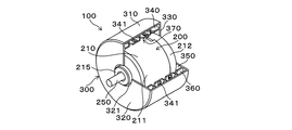
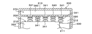
図1は一実施形態に係るモータ100の全体斜視図、図2はモータ100の内部構造を示す一部断面図である。このモータ100は、モータ部200と、モータ部200を収容するモータカバー300とから構成されている。
Hereinafter, an embodiment of the present invention will be described with reference to the drawings.
[1] Overall Structure of Motor FIG. 1 is an overall perspective view of a
モータ部200は、円筒状のハウジング210内に、中心にシャフト250を有するロータとステータ(いずれも図示略)が設けられた一般的なインナーロータ型のモータである。ステータはハウジング210の内周面に固定され、一方、ロータはステータの内側に配されシャフト250を介してハウジング210に回転可能に支持されており、シャフト250の一端部が出力軸としてハウジング210の中心から突出している。
The
ハウジング210は、第1ハウジング211と第2ハウジング212との組み合わせで構成されている。第1ハウジング211の端面の中心には円形状のフロントボス部215が形成されており、シャフト250はフロントボス部215を貫通している。
The
モータカバー300は円筒状であって、円筒部310の一端側および他端側に上板部320および下板部330を有している。上板部320の中心には円形状の嵌合孔321が形成されている。モータカバー300の内部の外周寄りには、円筒状の壁部340が同心状に形成されている。この壁部340によってモータカバー300の内部は径方向に仕切られ、壁部340の内側に内周側の空間350が形成され、壁部340の外側に外周側の空間360が形成されている。
The
モータ部200は、モータカバー300に対し、フロントボス部215が嵌合孔321に嵌合され、第1ハウジング211および第2ハウジング212の各端面がそれぞれ上板部320および下板部330の内面に当接した状態で、内周側の空間350に収容されている。
In the
[2]吸音器の構造
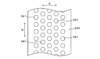
モータカバー300内の壁部340には、内周側の空間350と外周側の空間360とを連通する複数の円形状の孔341が、壁部340の全域に形成されている。図3は壁部340を平らに展開した状態を示し、同図に示すように孔341は周方向Rに沿って等間隔をおいて形成された一列が、軸方向Aに等間隔をおいて複数列(図示例では5列)形成され、軸方向Aに隣り合う列の孔341が周方向に互いにずれた全体として千鳥状に点在するパターンに形成されている。これら壁部340の複数の孔341と、外周側の空間360とによって、モータ部200から発生する音波の所定周波数を減衰させる吸音器370が構成されている。
[2] Structure of Sound Absorber A plurality of
[3]吸音器の音減衰作用
上記モータ100は、モータ部200が運転されるとモータ部200から発生する音はハウジング210から放射されるが、その音は、吸音器370による以下の作用によって低減する。
[3] Sound Attenuating Action of Sound Absorber In the
すなわち、モータ部200のハウジング210から放射した音は、モータカバー300の壁部340の孔341内の空気を音圧加振する。すると、孔341内の空気が質量、外周側の空間360の空気層がばねとなる振動現象が起こり、孔341内の空気と、孔341の外周側の表面すなわち孔341と外周側の空間360との境界面との間にせん断摩擦が起こって音のエネルギーが熱エネルギーに変換する。また、孔341内では空気が振動することで渦が発生して摩擦が生じ、これにより音のエネルギーが熱エネルギーに変換する。このように吸音器370では2種類の音のエネルギーの熱エネルギーへの変換作用が起こり、このためモータ部200から発生する音は減衰し、結果として騒音が低減する。
That is, the sound radiated from the
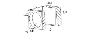
上記吸音器370の吸音特性のピーク周波数ωmは、図4に示す単孔モデルにおける表1に示す各諸元を下記式(1)にあてはめることによって求められる。単孔モデルとは、吸音器370を、1つの孔341と、その1つの孔341に対応した外周側の空間360に単純化したモデルを言う。なお、表1で示す管路面積とは、図4のSの面積、すなわち、孔341から円筒部310の内周面にわたる孔341に対応した断面四角形状の管路の断面積であって、孔341にほぼ外接する四角形の面積となる。なおその管路は、内周側から外周側にむかってテーパ状に広がるため内周側と外周側とでは若干の差異(外周側の方が大きい)があるが、ここでは簡易的に差異はなく同じと考慮する。
The peak frequency ω m of the sound absorption characteristic of the
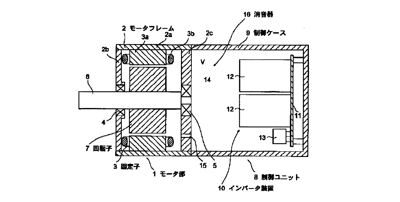
上記のように吸音器370によるモータ部200の騒音低減効果を得るには、モータ部200から発生する音の周波数を予め把握し、その周波数が上記ピーク周波数ωmに合致するように、吸音器370における孔341の寸法と外周側の空間360の深さ(径方向の奥行き寸法)を設定する。孔341の寸法は、孔341の開口面積および孔341の奥行き寸法(=壁部340の厚さ)である。
In order to obtain the noise reduction effect of the
式(1)から求められた孔341の寸法と外周側の空間360の深さに基づいてモータカバー300を設計することにより、吸音器370の吸音特性を単孔モデルと同様に得ることができる。また、モータ部200の音はハウジング210の全面から放射されることから、孔341は上記のように壁部340の全域に形成されていることが望ましく、また、均等に配置されていることが望ましい。
By designing the
本発明は、低騒音のモータとして好適である。 The present invention is suitable as a low noise motor.
100…モータ
200…モータ部
210…ハウジング
300…モータカバー
340…壁部
341…孔
350…内周側の空間
360…外周側の空間
370…吸音器
DESCRIPTION OF
Claims (3)
前記モータ部を収容する円筒状のモータカバーと、
を備えたモータであって、
前記モータカバーの内部には、該内部を内周側の空間と外周側の空間とに仕切る円筒状の壁部が設けられ、
前記モータ部は前記内周側の空間に収容され、
前記壁部には前記内周側の空間と前記外周側の空間とを連通する孔が形成され、
前記外周側の空間と前記孔とによって、前記モータ部から発生する音波の所定周波数を減衰させる吸音器が構成されることを特徴とするモータ。 A motor portion in which a rotor and a stator are provided in a cylindrical housing;
A cylindrical motor cover that houses the motor unit;
A motor equipped with
Inside the motor cover, a cylindrical wall portion is provided that partitions the interior into an inner circumferential space and an outer circumferential space,
The motor part is accommodated in the inner space,
The wall is formed with a hole that communicates the space on the inner peripheral side and the space on the outer peripheral side,
The motor characterized in that a sound absorber for attenuating a predetermined frequency of sound waves generated from the motor unit is constituted by the outer peripheral space and the hole.
Priority Applications (1)
| Application Number | Priority Date | Filing Date | Title |
|---|---|---|---|
| JP2016085729A JP2017195730A (en) | 2016-04-22 | 2016-04-22 | motor |
Applications Claiming Priority (1)
| Application Number | Priority Date | Filing Date | Title |
|---|---|---|---|
| JP2016085729A JP2017195730A (en) | 2016-04-22 | 2016-04-22 | motor |
Publications (1)
| Publication Number | Publication Date |
|---|---|
| JP2017195730A true JP2017195730A (en) | 2017-10-26 |
Family
ID=60155053
Family Applications (1)
| Application Number | Title | Priority Date | Filing Date |
|---|---|---|---|
| JP2016085729A Pending JP2017195730A (en) | 2016-04-22 | 2016-04-22 | motor |
Country Status (1)
| Country | Link |
|---|---|
| JP (1) | JP2017195730A (en) |
Cited By (4)
| Publication number | Priority date | Publication date | Assignee | Title |
|---|---|---|---|---|
| JP2019088083A (en) * | 2017-11-06 | 2019-06-06 | キヤノン株式会社 | Motor unit and image formation device |
| CN115173619A (en) * | 2022-06-17 | 2022-10-11 | 江苏华源防爆电机有限公司 | Servo motor |
| CN116094238A (en) * | 2023-02-16 | 2023-05-09 | 电子科技大学中山学院 | Permanent magnet synchronous motor |
| JP2024063805A (en) * | 2022-10-27 | 2024-05-14 | 三井金属アクト株式会社 | Vehicle sliding door opening and closing device |
Citations (5)
| Publication number | Priority date | Publication date | Assignee | Title |
|---|---|---|---|---|
| JPH07305974A (en) * | 1994-05-12 | 1995-11-21 | Kuken Kogyo Kk | Silencer |
| JPH0979199A (en) * | 1995-09-13 | 1997-03-25 | Hitachi Ltd | Electric blower |
| JP2000027798A (en) * | 1998-07-10 | 2000-01-25 | Mitsubishi Electric Corp | Blower |
| WO2001011206A2 (en) * | 1999-08-11 | 2001-02-15 | Türk Elektrik Endüstrisi A.Ş. | Perforated acoustic silencer for electrical motors |
| JP2005062661A (en) * | 2003-08-19 | 2005-03-10 | Daikin Ind Ltd | Air blower noise reduction device |
-
2016
- 2016-04-22 JP JP2016085729A patent/JP2017195730A/en active Pending
Patent Citations (5)
| Publication number | Priority date | Publication date | Assignee | Title |
|---|---|---|---|---|
| JPH07305974A (en) * | 1994-05-12 | 1995-11-21 | Kuken Kogyo Kk | Silencer |
| JPH0979199A (en) * | 1995-09-13 | 1997-03-25 | Hitachi Ltd | Electric blower |
| JP2000027798A (en) * | 1998-07-10 | 2000-01-25 | Mitsubishi Electric Corp | Blower |
| WO2001011206A2 (en) * | 1999-08-11 | 2001-02-15 | Türk Elektrik Endüstrisi A.Ş. | Perforated acoustic silencer for electrical motors |
| JP2005062661A (en) * | 2003-08-19 | 2005-03-10 | Daikin Ind Ltd | Air blower noise reduction device |
Cited By (4)
| Publication number | Priority date | Publication date | Assignee | Title |
|---|---|---|---|---|
| JP2019088083A (en) * | 2017-11-06 | 2019-06-06 | キヤノン株式会社 | Motor unit and image formation device |
| CN115173619A (en) * | 2022-06-17 | 2022-10-11 | 江苏华源防爆电机有限公司 | Servo motor |
| JP2024063805A (en) * | 2022-10-27 | 2024-05-14 | 三井金属アクト株式会社 | Vehicle sliding door opening and closing device |
| CN116094238A (en) * | 2023-02-16 | 2023-05-09 | 电子科技大学中山学院 | Permanent magnet synchronous motor |
Similar Documents
| Publication | Publication Date | Title |
|---|---|---|
| US7658592B1 (en) | Slots in fan housing to reduce tonal noise | |
| JP2009145891A (en) | Absorbent structure for attenuating noise, particularly noise generated by rotor generator noise, and rotor duct including the same | |
| JP2017141672A (en) | Fan motor | |
| WO2013078927A1 (en) | Silencer | |
| WO2001098653A1 (en) | A wind turbine wing with noise reduction means | |
| TWI735813B (en) | Noise reduction fan device | |
| JP2010071475A (en) | Ceiling embedded ventilation fan | |
| JP5135967B2 (en) | Centrifugal blower | |
| JP2016133226A (en) | Noise eliminator of blower | |
| CN208765234U (en) | Assembling bracket, fan assembly and air conditioner | |
| JP5309516B2 (en) | Centrifugal blower | |
| KR20050006170A (en) | Noise reducing device | |
| JP6277419B2 (en) | Blower | |
| CN208671181U (en) | Assembling bracket, fan assembly and air conditioner | |
| JP6221515B2 (en) | Electric blower assembly | |
| JP2019205536A (en) | mixer | |
| JP2019074030A (en) | Centrifugal fan | |
| CN109340193B (en) | Diversion air channel, airflow driving piece and range hood | |
| CN210977939U (en) | Shell assembly and bladeless fan | |
| JP2013040615A (en) | Centrifugal blower | |
| JP7353788B2 (en) | Blower and blower housing | |
| CN221760221U (en) | Clothes processing device and its box | |
| CN209278168U (en) | Fan box, fan and communication equipment | |
| CN216867055U (en) | Noise suppression fan | |
| JP4295255B2 (en) | Noise reduction device and vacuum cleaner |
Legal Events
| Date | Code | Title | Description |
|---|---|---|---|
| A621 | Written request for application examination |
Free format text: JAPANESE INTERMEDIATE CODE: A621 Effective date: 20171006 |
|
| A977 | Report on retrieval |
Free format text: JAPANESE INTERMEDIATE CODE: A971007 Effective date: 20180816 |
|
| A131 | Notification of reasons for refusal |
Free format text: JAPANESE INTERMEDIATE CODE: A131 Effective date: 20180827 |
|
| A02 | Decision of refusal |
Free format text: JAPANESE INTERMEDIATE CODE: A02 Effective date: 20190301 |