JP2017196247A - Golf club with air layer formed on head surface - Google Patents
Golf club with air layer formed on head surface Download PDFInfo
- Publication number
- JP2017196247A JP2017196247A JP2016090809A JP2016090809A JP2017196247A JP 2017196247 A JP2017196247 A JP 2017196247A JP 2016090809 A JP2016090809 A JP 2016090809A JP 2016090809 A JP2016090809 A JP 2016090809A JP 2017196247 A JP2017196247 A JP 2017196247A
- Authority
- JP
- Japan
- Prior art keywords
- ridge
- head
- golf club
- ridges
- sole surface
- Prior art date
- Legal status (The legal status is an assumption and is not a legal conclusion. Google has not performed a legal analysis and makes no representation as to the accuracy of the status listed.)
- Pending
Links
Images



Classifications
-
- A—HUMAN NECESSITIES
- A63—SPORTS; GAMES; AMUSEMENTS
- A63B—APPARATUS FOR PHYSICAL TRAINING, GYMNASTICS, SWIMMING, CLIMBING, OR FENCING; BALL GAMES; TRAINING EQUIPMENT
- A63B53/00—Golf clubs
- A63B53/04—Heads
- A63B53/0466—Heads wood-type
-
- A—HUMAN NECESSITIES
- A63—SPORTS; GAMES; AMUSEMENTS
- A63B—APPARATUS FOR PHYSICAL TRAINING, GYMNASTICS, SWIMMING, CLIMBING, OR FENCING; BALL GAMES; TRAINING EQUIPMENT
- A63B53/00—Golf clubs
- A63B53/04—Heads
- A63B53/0433—Heads with special sole configurations
-
- A—HUMAN NECESSITIES
- A63—SPORTS; GAMES; AMUSEMENTS
- A63B—APPARATUS FOR PHYSICAL TRAINING, GYMNASTICS, SWIMMING, CLIMBING, OR FENCING; BALL GAMES; TRAINING EQUIPMENT
- A63B53/00—Golf clubs
- A63B53/04—Heads
- A63B53/0437—Heads with special crown configurations
-
- A—HUMAN NECESSITIES
- A63—SPORTS; GAMES; AMUSEMENTS
- A63B—APPARATUS FOR PHYSICAL TRAINING, GYMNASTICS, SWIMMING, CLIMBING, OR FENCING; BALL GAMES; TRAINING EQUIPMENT
- A63B53/00—Golf clubs
- A63B53/04—Heads
- A63B53/0408—Heads characterised by specific dimensions, e.g. thickness
-
- A—HUMAN NECESSITIES
- A63—SPORTS; GAMES; AMUSEMENTS
- A63B—APPARATUS FOR PHYSICAL TRAINING, GYMNASTICS, SWIMMING, CLIMBING, OR FENCING; BALL GAMES; TRAINING EQUIPMENT
- A63B53/00—Golf clubs
- A63B53/04—Heads
- A63B53/0445—Details of grooves or the like on the impact surface
-
- A—HUMAN NECESSITIES
- A63—SPORTS; GAMES; AMUSEMENTS
- A63B—APPARATUS FOR PHYSICAL TRAINING, GYMNASTICS, SWIMMING, CLIMBING, OR FENCING; BALL GAMES; TRAINING EQUIPMENT
- A63B60/00—Details or accessories of golf clubs, bats, rackets or the like
- A63B60/006—Surfaces specially adapted for reducing air resistance
Landscapes
- Health & Medical Sciences (AREA)
- General Health & Medical Sciences (AREA)
- Physical Education & Sports Medicine (AREA)
- Life Sciences & Earth Sciences (AREA)
- Engineering & Computer Science (AREA)
- Wood Science & Technology (AREA)
- Golf Clubs (AREA)
Abstract
【課題】スウィング時の周囲空気のクラブヘッドへのリタッチを抑制し、ヘッドの空気抵抗を減少させるクラブの提供。【解決手段】ウッドクラブヘッドとシャフトからなるゴルフクラブにおいて、少なくともクラブヘッドのソール面に複数の0.2mm以上3mm以下の高さ、幅1〜5mmのリッジ12a〜12cを時計回りに変位して傾斜させ、放射状に配設し、クラブヘッドソール面と周囲空気層との間に複数のリッジにより形成させる渦流を介在させることによりスイング時の空気抵抗を減少させる。【選択図】図2To provide a club that suppresses retouching of ambient air to a club head during a swing and reduces the air resistance of the head. In a golf club comprising a wood club head and a shaft, a plurality of ridges 12a to 12c having a height of 0.2 mm to 3 mm and a width of 1 to 5 mm are displaced clockwise on at least the sole surface of the club head. The air resistance at the time of swing is reduced by inclining and arranging radially, and interposing a vortex formed by a plurality of ridges between the club head sole surface and the surrounding air layer. [Selection] Figure 2
Description
本発明は、クラブヘッドのソール面に渦流発生による滞留空気層が形成されるウッドタイプのゴルフクラブに関するものであり、詳しくは、特にダウンスウィイング時のヘッドの空気抵抗を軽減してスムーズなスウィングを実現するウッドタイプのゴルフクラブに関する。 The present invention relates to a wood-type golf club in which a staying air layer is formed on the sole surface of a club head due to eddy current generation. More specifically, the present invention relates to a smooth swing especially by reducing the air resistance of the head during downswing. The present invention relates to a wood type golf club that achieves the above.
ドライバーショットの飛距離を増大させるには、ウッドタイプのゴルフクラブのスウィング速度を増大させることが必要である。そのためには、スウィング時にヘッドを高速度で移動するときに生じる空気抵抗をできるだけ減少させなければならない。この空気抵抗を減少させる従来技術としては、ヘッド本体の形状を二等辺三角形とし、更に、ヘッド本体全体の形状を偏平な砲弾形状とし、ヘッド本体の空気抵抗を減少させ、更に、ヒール部にネック部を設けたものが提案されている(特許文献1)。然し、ヘッド形状を偏平形状としてヘッドの厚みを薄くするには限度があり、空気抵抗を減少させる効果はあまり期待できない。 In order to increase the flight distance of driver shots, it is necessary to increase the swing speed of a wood type golf club. For this purpose, the air resistance generated when moving the head at high speed during swing must be reduced as much as possible. As a conventional technique for reducing the air resistance, the shape of the head body is an isosceles triangle, the shape of the entire head body is a flat shell shape, the air resistance of the head body is reduced, and the neck at the heel part is further reduced. The thing which provided the part is proposed (patent document 1). However, there is a limit to reducing the thickness of the head by making the head shape flat, and the effect of reducing the air resistance cannot be expected so much.
そこで、ウッドタイプのゴルフクラブにおいて、スウィイングすると、ヘッドの後方に渦が生じて空気抵抗が大きくなり、スウィング速度を上昇させることができない要因になっていることに着目し、ゴルフクラブヘッドHのクラウン部の中央付近の空気剥離点の後方に、複数のディンプルを設け、ヘッドの後方に発生する空気の乱れをディンプルで減少させるようにしたウッドタイプのゴルフクラブが提案されるに至っている(特許文献2)。 Therefore, paying attention to the fact that when swinging in a wood type golf club, a vortex is generated behind the head, air resistance increases, and the swing speed cannot be increased. A wood-type golf club has been proposed in which a plurality of dimples are provided behind the air separation point near the center of the part, and the air turbulence generated behind the head is reduced by the dimples (Patent Literature). 2).
そこで、従来のウッドタイプのゴルフクラブヘッドを、スウィイング方向に垂直に切断した縦断面の二次元モデルでみる。風洞内で、前方フェース方向から空気を整流状態にして送風すると(図1(c))、クラウン面の表面に沿って流れる空気流は、クラウン面の頂部を過ぎた位置でクラウン面から剥離し、その後方に空気流の乱れを生させ、空気抵抗の要因となると考えられる。しかしながら、スウィング中のヘッドの軌跡(図1(a))を見ると、ヘッドのトップ位置からダウンスウィングを経てインパクトに至るスウィング軌道ではヘッドのソール面と周囲空気流との接触が支配的であることがわかる。そして、わずかにインパクトの前後でボールに対し、はじめてフェース面がスクエアになり、ヘッドの上下、クラウン面とソール面とに対して平行に流れる空気流が形成される(図1(c))に過ぎない。そのため、ヘッドクラウン部後方に形成したディンプルには空気抵抗の低減効果が少ない。そのため、クラブスウィングを力学的を見ると、クラブスウィング時にはグリップBとシャフト先端Aとがなすシャフト線ABに対しヘッド重心GとグリップBとを結ぶ線分BGとは幾分角度の開きがあり、この角度の開きがインパクト時にヘッドのトウCがトウダウンする現象だけでなく、スウィング時にシャフトに捩れを引き起こし、トウイン現象を起こさせることがわかる。そこで、従来、ヘッドの重心をヒール側に移動させることでかかる問題を解消しようとしたが、かかる問題の主たる原因は、スウィング時の空気の粘りによるヘッド周囲面へのへばり付きによるものであり、スウィング中のヘッドの空気抵抗を減少させるにはスウィング軌道から主としてソール面の空気抵抗の低減が重要であることを見出した。 Therefore, a conventional wood-type golf club head is viewed as a two-dimensional model with a longitudinal section cut perpendicular to the swinging direction. When air is rectified from the front face direction in the wind tunnel and blown (FIG. 1 (c)), the air flow flowing along the surface of the crown surface separates from the crown surface at a position past the crown surface. It is thought that it causes turbulence of the air flow behind it and causes air resistance. However, looking at the trajectory of the head during the swing (FIG. 1 (a)), the contact between the head sole surface and the surrounding airflow is dominant in the swing trajectory from the top position of the head to the impact through the downswing. I understand that. Then, the face surface becomes square for the first time before and after the impact, and an air flow that flows parallel to the top and bottom of the head and the crown surface and the sole surface is formed (FIG. 1 (c)). Not too much. For this reason, dimples formed behind the head crown portion have little air resistance reduction effect. Therefore, when looking at the dynamics of the club swing, the line segment BG connecting the head center of gravity G and the grip B with respect to the shaft line AB formed by the grip B and the shaft tip A at the time of the club swing has a slight angle difference, It can be seen that the opening of this angle not only causes the head toe C to tow down at the time of impact, but also causes the torsion of the shaft during the swing, causing a toe-in phenomenon. Therefore, conventionally, we tried to solve this problem by moving the center of gravity of the head to the heel side, but the main cause of this problem is due to the sticking of air around the head due to stickiness of the air during swinging. In order to reduce the air resistance of the head during the swing, it was found that it is important to reduce the air resistance of the sole surface mainly from the swing track.
本発明者はかかる観点に基づき、鋭意研究の結果、スウィング時の周囲空気の粘りによるへばり付きをなくすには周囲空気とクラブヘッド表面との間に空気層を介在させるのがよいと考え、本発明を完成した。本発明は少なくともクラウン面とソール面を有するクラブヘッドとシャフトからなるゴルフクラブにおいて、クラブヘッドの少なくともソール面にスウィング時のヘッド周囲を流れる空気に対しこれを受けて障壁となる第1のリッジと該第1のリッジに対し間隔をおいて空気流後方に第2リッジとを設け、第1のリッジの前壁に衝突し、第1のリッジを越えて第2のリッジの前方に流れ込む空気流を第2のリッジで受け、第2のリッジの前壁に衝突して反転させるリッジ構造とすることにより第1のリッジと第2のリッジとの間に渦流を形成させ、クラブヘッド面と周囲空気との間に空気層を介在させることを特徴とするゴルフクラブにある。 Based on this viewpoint, the present inventor believes that, as a result of earnest research, it is better to interpose an air layer between the ambient air and the club head surface in order to eliminate stickiness due to the stickiness of the ambient air during swinging. The present invention has been completed. The present invention relates to a golf club comprising a club head having at least a crown surface and a sole surface and a shaft, and a first ridge serving as a barrier against air flowing around the head at the time of swing on at least the sole surface of the club head; A second ridge is provided behind the air flow at a distance from the first ridge, collides with the front wall of the first ridge, and flows into the front of the second ridge across the first ridge. Is received by the second ridge and collides with the front wall of the second ridge so as to be reversed, thereby forming a vortex between the first ridge and the second ridge, and the club head surface and the surrounding area. A golf club is characterized in that an air layer is interposed between air and air.
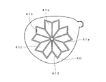
クラブヘッド面と周囲空気流との間に空気層を介在させるリッジ構造は、図3に示すように、ヘッドのソール面Sから突出する第1のリッジR1に衝突した空気流が第1のリッジR1を越えて空気流後方の第2のリッジR2に衝突し、反転して渦流Wを形成するのが肝要であり、スウィング時のヘッドのソール面の半時計方向へ回転変位する軌道(図1(a))を考慮すると、第1のリッジに対し第2のリッジは時計回りに角度変位を持たせるのが好ましく、まず、第1のリッジに対し第2のリッジは放射状に角度変位させる必要がある。次いで、第1のリッジと第2のリッジと空間は実質的に囲まれた空間を形成することにより、第2のリッジに衝突して形成される渦流の滞留を確保するのが好ましい。かかる原則の下で、第1の形態はソール面の周囲端に沿ってU字形のリッジ12aを形成し、そこから一定間隔で周囲端に延びる放射状のリッジ12b、12cを形成して分割することによりリッジ構造を達成できる(図2参照)。第2の形態はヘッドのソール面20に相似の大小複数の多角形21,22,23(図面では5角形)を一定間隔で多重に重ね、その底辺21aをフェース面23にほぼ平行に置き、その多角形稜点をつなぐ様に放射状に延びるリッジ24で区切ってリッジ構造を形成することができる(図4参照、図中多角形は5角形の3重)。又、ソウル面30にリッジで形成した多重円31、32,33を放射状に延びるリッジ34で区切り、分割することによりリッジ構造を形成することもできる(図5参照、円形3重)。さらに、相似形の多重空間は複数の矢羽形状41a,41b,41c,41d,41eの周囲をリッジで形成し、閉鎖した空間を有するリッジを放射状に重ねることによってもリッジ構造を形成することができる(図6参照、図中矢羽は5個)。以上は規則的に風車形状のリッジ構造を形成する方法であるが、図7に示すように、大略N形状に屈曲する稲妻状のリッジ51、52,53を時計周りにリッジ傾斜が変化するように配設することによってもリッジ構造を形成することができる。要するに本発明では、第1にリッジはその放射状に延びる、傾斜方向がスウィング時のソールの変位に従って時計方向に変位することで効率よい障壁となることが必要で、ヘッド面と周囲空気との間に滞留する空気層を形成するための条件である。そして傾斜したリッジが実質的に閉鎖空間を形成するのが空気層の滞留時間を確保するのに好ましい条件である。
In the ridge structure in which an air layer is interposed between the club head surface and the ambient air flow, as shown in FIG. 3, the air flow colliding with the first ridge R1 protruding from the sole surface S of the head is the first ridge. It is important to collide with the second ridge R2 behind the air flow beyond R1 and reverse to form the vortex W, and the trajectory rotationally displaces counterclockwise on the sole surface of the head during swinging (FIG. 1). In consideration of (a)), it is preferable that the second ridge has a clockwise angular displacement with respect to the first ridge. First, the second ridge needs to be radially angularly displaced with respect to the first ridge. There is. Next, it is preferable to ensure the retention of the vortex formed by colliding with the second ridge by forming a substantially enclosed space between the first ridge and the second ridge. Under such a principle, the first embodiment forms a U-shaped ridge 12a along the peripheral edge of the sole surface, and then forms and divides the
次いで、本発明において形成されるリッジのサイズはボールの飛翔速度及び回転数を考慮して定められるが、一般にゴルフボールにおいては高さ0.2mm以上3mm以下、幅1〜5mmとするのが適当である。リッジ間の間隔はリッジ高さ、幅との相関関係で決定されるが、リッジの立ち上がりは空気流との障壁となるように形成されるのが好ましい。 Next, the size of the ridge formed in the present invention is determined in consideration of the flying speed and the number of rotations of the ball. In general, it is appropriate that the golf ball has a height of 0.2 mm to 3 mm and a width of 1 to 5 mm. It is. The interval between the ridges is determined by the correlation with the height and width of the ridge, but it is preferable that the rise of the ridge is formed to be a barrier against the air flow.
本発明によれば、図3に示すように、空気流はソール面Sから隆起する第1次リッジR1に衝突して立ち上がり、周囲空気流Fで後方第2次リッジR2との間に押し込まれ、第2次リッジR2に衝突して反転し、逆流を発生させ、これを繰り返すことによりクラブヘッドソール面と周囲空気層との間に複数のリッジにより形成させる渦流Wからなる空気層を介在させることができる。それにより、周囲空気のクラブヘッドへのリタッチを抑制し、ヘッドの空気抵抗を減少させることができる。 According to the present invention, as shown in FIG. 3, the air flow collides with the primary ridge R1 rising from the sole surface S and rises and is pushed between the rear secondary ridge R2 by the ambient air flow F. , Collides with the secondary ridge R2 and reverses to generate a reverse flow. By repeating this, an air layer composed of a vortex W formed by a plurality of ridges is interposed between the club head sole surface and the surrounding air layer. be able to. Thereby, retouching of ambient air to the club head can be suppressed, and the air resistance of the head can be reduced.
かかるリッジR1,R2・・・はヘッドの周囲空気流Fの壁への衝突により立ち上がる空気流をその外の空気流によりヘッド表面に押し下げ、後方の第2次リッジR2に衝突させることにより逆流を発生させ、第1次リッジと第2次リッジ間に渦流Wを形成させる。この動作を順次後方のリッジとの間で繰りかえされることが重要であり、前述したように、リッジ高さとリッジ間隔はリッジ間に渦流Wが形成されるように調整されるのがよい。したがって、リッジのヘッド表面への配置形状は連続又は断続的リッジによって形成してもよく、線状リッジに限られるものでない。また、リッジは連続しても断続して形成してもよい。 The ridges R1, R2,... Reverse the reverse flow by pushing the air flow rising due to the collision of the air flow F around the head against the wall against the head surface by the external air flow and colliding with the second secondary ridge R2. And a vortex W is formed between the primary ridge and the secondary ridge. It is important that this operation is sequentially repeated with the rear ridge, and as described above, the ridge height and the ridge interval are preferably adjusted so that a vortex W is formed between the ridges. Therefore, the arrangement shape of the ridge on the head surface may be formed by a continuous or intermittent ridge, and is not limited to a linear ridge. The ridge may be formed continuously or intermittently.
本発明のリッジは本来空気抵抗の発生に支配的なソール面に設けられるが、クラウン面にも同等のリッジ構造を形成してもよい。また、クラウン面においてはフェース面がスクエアになるヒッテング前後(図1(c))を考慮してフェース面に平行な線状リッジ11a,11aを並列して設け、後端に直交する一対のL形リッジ11cを設けるようにしてもよい。
Although the ridge of the present invention is provided on the sole surface that is dominant in generating air resistance, an equivalent ridge structure may be formed on the crown surface. Further, in consideration of the front and back of the crown surface where the face surface is square (FIG. 1C), linear ridges 11a and 11a parallel to the face surface are provided in parallel, and a pair of L's orthogonal to the rear end is provided. A
シャフト曲げモーメント及び捩れモーメントは、スウィング中に図1に示すように発生する。
(1)ダウンスウィング開始時、スウィングのトップでは、重力によってヘッドが下がりシャフトは重力とは反対方向に曲がる。
(2)及び(3)ダウンスウィング開始されるとゴルファーの回転方向にグリップから動き、その力はシャフトからヘッドに働き、シャフトに曲げモーメントが発生する。
(4)普通のスウィングでは腰の辺りで曲げモーメントが反力によって元に戻り、逆しなりを開始する。
(5)その逆しなりは次第に大きくなり、そのときに同時にシャフトに捩れモーメントも発生する。
(6)そしてインパクト時には逆しなりが戻り始め、捩れモーメントの返りによりヘッドの先端がトウイン現象を起こす。
この捩れモーメントを減少させるためにヘッドの重心をヒール側に移行し、力学的に解消する研究がなされてきた。今回、我々は、この捩れモーメント及びシャフトのベントを空気の流れによって減少させるものである。
Shaft bending moment and torsional moment are generated during swing as shown in FIG.
(1) At the start of downswing, at the top of the swing, the head is lowered by gravity and the shaft bends in the opposite direction to gravity.
(2) and (3) When the downswing is started, the golfer moves from the grip in the direction of rotation, and the force acts on the head from the shaft, and a bending moment is generated on the shaft.
(4) In normal swing, the bending moment is restored to the original by the reaction force around the waist, and reverse rotation starts.
(5) The reverse is gradually increased, and at the same time, a torsional moment is generated in the shaft.
(6) At the time of impact, the reverse begins to return, and the tip of the head causes a toe-in phenomenon due to the return of the torsional moment.
In order to reduce the torsional moment, studies have been made to shift the center of gravity of the head to the heel side to eliminate it dynamically. This time we reduce this torsional moment and shaft vent by air flow.
上述のダウンスウィングは右利きのゴルファーの場合、身体とともに左回転方向に回るためシャフトに捩れが生じる。これはグリップAとヘッドB間のシャフトABとグリップAとヘッドの重心Gとのなす線分(図中点線)との乖離角度により重心Gとシャフト端Bとの間に作用する重力によって生じる。この捩れモーメントを減少させるには上述した重心位置Gのヒール側への移動だけでなく、今回ヘッドのスウィング時のヘッドの空気抵抗を減少させることにより、捩れモーメントを減少させる必要がある、 In the case of a right-handed golfer, the above-described downswing rotates in the counterclockwise direction together with the body, causing the shaft to twist. This is caused by the gravity acting between the center of gravity G and the shaft end B due to the divergence angle between the shaft AB between the grip A and the head B and the line segment (dotted line in the figure) formed by the grip A and the center of gravity G of the head. In order to reduce this torsional moment, it is necessary to reduce the torsional moment by reducing the air resistance of the head during the swing of the head this time, as well as the above movement of the center of gravity G to the heel side.
図1(a)のスウィング軌道を見ると、トップ(1)からフィニッシュ(6)までの間に発生する空気抵抗は、ドライバーのフェース部分によって一番惹起され、インパクト寸前とインパクト直後であり極わずかな距離と極わずかな時間である。したがって、インパクト前後の空気抵抗は図2に示されるように、ヘッドの上下、クラウン面とソール面を流れる空気流によって惹起されるが、それはスウィング中の10%くらいの距離と時間であり、それ以外の、スウィング中の遠心力が、長く、また速い速度でヘッドに対する空気抵抗に関わる。そして、図1(a)のクラブヘッドの旋回をみると、ソール部分の空気との接触は常に100%空気と接触している。そのことに注目し、少なくともソール部分の空気抵抗を減少させるとヘッド自体の空気抵抗が減少する。また、同時にヘッドのサイド部分とクラウン部分もあわせて空気抵抗を減少させるのが好ましいことを見出した。なぜなら、ダウンスウィング中、ヘッドに対する空気抵抗が大きければヘッドから生じるシャフトに対しての捩れも大きくなり、その反力によってシャフトには、曲げモーメントと捩れモーメントも大きくなる。シャフトにかかるモーメントは、空気との接触部分の面積と時間に比例するので、ソール部分の空気の流れによる空気との摩擦を減少させることで解決できた。同じようにヘッドのサイド部分及びクラウン部分も層流から乱流にすることでより空気抵抗の減少が見られた。このことにより、スウィングをするとヘッドの重量もかなり軽く感じスウィングも簡単にボールにヒットできるようになった。また、同一人のスウィングでも飛距離が10ヤードから20ヤード伸びることが確認できるので、ヘッドスピードは5%以上向上するものとなる。 Looking at the swing trajectory in Fig. 1 (a), the air resistance generated from the top (1) to the finish (6) is caused most by the face part of the driver, and it is just before the impact and just after the impact. Distance and very little time. Therefore, as shown in Fig. 2, the air resistance before and after impact is caused by the air flow flowing up and down the head, the crown surface and the sole surface, which is about 10% of the distance and time during the swing. The centrifugal force during the swing is related to the air resistance against the head at a long and high speed. When the club head turns in FIG. 1 (a), the contact of the sole portion with the air is always 100% with the air. When attention is paid to this, at least when the air resistance of the sole portion is reduced, the air resistance of the head itself is reduced. At the same time, it has been found that it is preferable to reduce the air resistance by combining the side portion and the crown portion of the head. This is because during downswing, if the air resistance against the head is large, the torsion of the shaft generated from the head also increases, and the reaction force increases the bending moment and torsional moment of the shaft. Since the moment applied to the shaft is proportional to the area and time of the contact portion with the air, it can be solved by reducing the friction with the air due to the air flow in the sole portion. In the same manner, the air resistance was further reduced by changing the side part and crown part of the head from laminar flow to turbulent flow. This made the head feel quite light when swinging, making it easy for the swing to hit the ball. Moreover, since it can be confirmed that the flight distance increases from 10 yards to 20 yards even in the swing of the same person, the head speed is improved by 5% or more.
ウッドクラブヘッドとシャフトからなるゴルフクラブにおいて、クラブヘッド10のクラウン面11には2本のリッジをトウ側からヒール側に向けて11a,11bを形成し、ヒール部には一対のL形リッジ11cを形成する(図2(a))。他方、ソール面12にフェース側からヒール側に向けてU字形リッジ12aを形成し、U字形リッジ12aから周囲輪郭に向けて複数本のリッジ12b,12bを間隔を置いて形成するとともに、スウィング中のヘッドの向きを考慮してヒール側に延びるリッジ12c、12cを形成する(図2(b))。複数のリッジの寸法は実施例では0.7mmの高さ、幅2.7mmとしたが、上述した一定の範囲で許容される。本実施例ではクラウン面11とソール面12と周囲空気流との間には渦流が介在し、周囲空気がヘッド面にリタッチすることなく、スムーズに流れることが解る(図2(c))。
In a golf club comprising a wood club head and a shaft, two ridges are formed on the
本発明によれば、第1次リッジに衝突して立ち上がった空気流を周囲空気流で後方第2次リッジ間に押し込み、第2次リッジに衝突させて逆流を発生させ、これを繰り返すことによりクラブヘッドソール面と周囲空気層との間に複数のリッジにより形成させる渦流を介在させることができる。それにより、周囲空気のクラブヘッドへのリタッチを抑制し、ヘッドの空気抵抗を減少させることができる。 According to the present invention, the air flow that has risen by colliding with the primary ridge is pushed between the rear secondary ridges by the ambient air flow, collided with the secondary ridge to generate a reverse flow, and this is repeated. A vortex formed by a plurality of ridges can be interposed between the club head sole surface and the surrounding air layer. Thereby, retouching of ambient air to the club head can be suppressed, and the air resistance of the head can be reduced.
リッジ形状はクラウン面では通常、フェース面を基準にそれに平行又はほぼ平行に0.2mmから3mmの範囲の高さ、幅1mmから5mmを有する線状のリッジによって形成することができるが、これに限られるものでない。かかるリッジはヘッドの周囲空気流の壁への衝突により立ち上がる空気流をその外の空気流によりヘッド表面に押し下げ、後方の第2次リッジに衝突させることにより逆流を発生させ、第1次リッジと第2次リッジ間に渦流を形成させ、この動作を順次後方のリッジとの間で繰りかえされることが重要であり、リッジ高さとリッジ間隔はリッジ間に渦流が形成されるように調整されるのがよい。したがって、リッジのヘッド表面への配置形状は連続又は断続的リッジによって形成してもよく、線状リッジに限られるものでない。 The ridge shape is usually formed on the crown surface by a linear ridge having a height in the range of 0.2 mm to 3 mm and a width of 1 mm to 5 mm parallel or almost parallel to the face surface. It is not limited. Such a ridge pushes down the air flow rising due to the collision of the air flow around the head to the head surface by the air flow outside the head and causes it to collide with the secondary ridge behind to generate a reverse flow. It is important that a vortex is formed between the secondary ridges, and this operation is sequentially repeated with the rear ridge, and the ridge height and the ridge interval are adjusted so that a vortex is formed between the ridges. It is good. Therefore, the arrangement shape of the ridge on the head surface may be formed by a continuous or intermittent ridge, and is not limited to a linear ridge.
Claims (11)
Priority Applications (4)
| Application Number | Priority Date | Filing Date | Title |
|---|---|---|---|
| JP2016090809A JP2017196247A (en) | 2016-04-28 | 2016-04-28 | Golf club with air layer formed on head surface |
| US15/170,455 US9975010B2 (en) | 2016-04-28 | 2016-06-01 | Golf-club provided with a club-head having surfaces configured to be covered by air vortex flows |
| CN201620808583.5U CN205964900U (en) | 2016-04-28 | 2016-07-28 | Golf ball pole at golf ball head surface formation air bed |
| TW105128616A TWI700112B (en) | 2016-04-28 | 2016-09-05 | Golf club formed with air layer on head surface |
Applications Claiming Priority (1)
| Application Number | Priority Date | Filing Date | Title |
|---|---|---|---|
| JP2016090809A JP2017196247A (en) | 2016-04-28 | 2016-04-28 | Golf club with air layer formed on head surface |
Publications (1)
| Publication Number | Publication Date |
|---|---|
| JP2017196247A true JP2017196247A (en) | 2017-11-02 |
Family
ID=58027247
Family Applications (1)
| Application Number | Title | Priority Date | Filing Date |
|---|---|---|---|
| JP2016090809A Pending JP2017196247A (en) | 2016-04-28 | 2016-04-28 | Golf club with air layer formed on head surface |
Country Status (4)
| Country | Link |
|---|---|
| US (1) | US9975010B2 (en) |
| JP (1) | JP2017196247A (en) |
| CN (1) | CN205964900U (en) |
| TW (1) | TWI700112B (en) |
Cited By (2)
| Publication number | Priority date | Publication date | Assignee | Title |
|---|---|---|---|---|
| US20230277904A1 (en) * | 2022-03-04 | 2023-09-07 | Sumitomo Rubber Industries, Ltd. | Golf club head and method for manufacturing the same |
| KR20250012441A (en) * | 2023-07-17 | 2025-01-24 | 정헌철 | Golf club |
Families Citing this family (15)
| Publication number | Priority date | Publication date | Assignee | Title |
|---|---|---|---|---|
| US8858359B2 (en) | 2008-07-15 | 2014-10-14 | Taylor Made Golf Company, Inc. | High volume aerodynamic golf club head |
| US20100016095A1 (en) * | 2008-07-15 | 2010-01-21 | Michael Scott Burnett | Golf club head having trip step feature |
| US8088021B2 (en) | 2008-07-15 | 2012-01-03 | Adams Golf Ip, Lp | High volume aerodynamic golf club head having a post apex attachment promoting region |
| US10888747B2 (en) | 2008-07-15 | 2021-01-12 | Taylor Made Golf Company, Inc. | Aerodynamic golf club head |
| US11213725B2 (en) * | 2011-10-31 | 2022-01-04 | Karsten Manufacturing Corporation | Golf club heads with turbulators and methods to manufacture golf club heads with turbulators |
| US10413788B2 (en) * | 2011-10-31 | 2019-09-17 | Karsten Manufacturing Corporation | Golf club heads with turbulators and methods to manufacture golf club heads with turbulators |
| US9839817B1 (en) * | 2014-04-23 | 2017-12-12 | Taylor Made Golf Company, Inc. | Golf club |
| US10518140B2 (en) * | 2016-06-01 | 2019-12-31 | Cross Technology Labo Co., Ltd. | Golf-club provided with a club-head having surfaces configured to be covered by air vortex flows |
| US10245481B1 (en) | 2017-12-21 | 2019-04-02 | Acushnet Compnay | Golf club head |
| JP7150586B2 (en) * | 2018-12-12 | 2022-10-11 | ブリヂストンスポーツ株式会社 | golf club head |
| WO2021012002A1 (en) * | 2019-07-19 | 2021-01-28 | Aerotec Power Pty Ltd | Improved sporting articles |
| EP4347060A4 (en) * | 2021-05-27 | 2025-07-09 | Karsten Mfg Corp | GOLF CLUB HEAD WITH FLEXIBLE SOLE |
| JP7722069B2 (en) * | 2021-09-03 | 2025-08-13 | 住友ゴム工業株式会社 | Golf club head |
| US20230166166A1 (en) * | 2021-11-08 | 2023-06-01 | Aerotec Power Pty Ltd | Sporting articles |
| JP2024106019A (en) * | 2023-01-26 | 2024-08-07 | グローブライド株式会社 | Golf club head and golf club equipped with the same |
Family Cites Families (6)
| Publication number | Priority date | Publication date | Assignee | Title |
|---|---|---|---|---|
| JPS60128664U (en) | 1984-02-04 | 1985-08-29 | ダイワゴルフ株式会社 | golf club head |
| JPH067484A (en) | 1992-06-24 | 1994-01-18 | Osawa Shokai:Kk | Golf club head |
| US5524890A (en) * | 1995-03-28 | 1996-06-11 | Kim; Jae S. | Golf club |
| USD382612S (en) * | 1995-10-10 | 1997-08-19 | GIC Golf Company, Inc. | Golf club head |
| USD501903S1 (en) * | 2003-12-22 | 2005-02-15 | Kouji Tanaka | Golf club head |
| US8608587B2 (en) * | 2011-10-31 | 2013-12-17 | Karsten Manufacturing Corporation | Golf club heads with turbulators and methods to manufacture golf club heads with turbulators |
-
2016
- 2016-04-28 JP JP2016090809A patent/JP2017196247A/en active Pending
- 2016-06-01 US US15/170,455 patent/US9975010B2/en active Active
- 2016-07-28 CN CN201620808583.5U patent/CN205964900U/en active Active
- 2016-09-05 TW TW105128616A patent/TWI700112B/en active
Cited By (4)
| Publication number | Priority date | Publication date | Assignee | Title |
|---|---|---|---|---|
| US20230277904A1 (en) * | 2022-03-04 | 2023-09-07 | Sumitomo Rubber Industries, Ltd. | Golf club head and method for manufacturing the same |
| US12458851B2 (en) * | 2022-03-04 | 2025-11-04 | Sumitomo Rubber Industries, Ltd. | Golf club head and method for manufacturing the same |
| KR20250012441A (en) * | 2023-07-17 | 2025-01-24 | 정헌철 | Golf club |
| KR102834548B1 (en) * | 2023-07-17 | 2025-07-14 | 정헌철 | Golf club |
Also Published As
| Publication number | Publication date |
|---|---|
| TW201737973A (en) | 2017-11-01 |
| CN205964900U (en) | 2017-02-22 |
| US20170312591A1 (en) | 2017-11-02 |
| TWI700112B (en) | 2020-08-01 |
| US9975010B2 (en) | 2018-05-22 |
Similar Documents
| Publication | Publication Date | Title |
|---|---|---|
| TWI700112B (en) | Golf club formed with air layer on head surface | |
| US5980394A (en) | Golf club woodhead with optimum aerodynamic structure | |
| US8678946B2 (en) | Golf club assembly and golf club with aerodynamic features | |
| US20120252597A1 (en) | Golf club assembly and golf club with aerodynamic features | |
| US8360900B2 (en) | Golf club assembly and golf club with aerodynamic features | |
| US10709941B2 (en) | Golf club head | |
| AU2002230584A1 (en) | Golf ball with grooved dimples | |
| JP2009279373A (en) | Wood club | |
| JP2002537914A (en) | Golf ball with contoured dimples | |
| JP2019162322A (en) | Wood type golf club head | |
| JP2005177507A (en) | Golf ball dimple pattern having overlapping dimples | |
| WO2010126808A1 (en) | Vertically curved face putter with multiple horizontal contact facets | |
| US20060014588A1 (en) | T-blade drag reduction device for use with sporting equipment shafts | |
| US9486676B1 (en) | Golf club with drag reduction surfacing | |
| US8562455B2 (en) | Method of forming a golf club head with improved aerodynamic characteristics | |
| US6019688A (en) | Golf ball with non-circular sickle-shaped dimples | |
| JP2004337327A (en) | Metal wood club | |
| JP2016539779A (en) | Golf ball having hitting line for hitting fade shot and draw shot, and manufacturing method thereof | |
| JP2016107022A (en) | Golf club head | |
| JP2009148533A (en) | Wood type golf club head | |
| US10518140B2 (en) | Golf-club provided with a club-head having surfaces configured to be covered by air vortex flows | |
| CN105080092A (en) | Golf tee | |
| JP2005237535A (en) | Wood type club | |
| US8696493B2 (en) | Golf club head with improved aerodynamic characteristics | |
| JP2013000237A (en) | Golf club head |