JP2017196708A - 圧入治具 - Google Patents
圧入治具 Download PDFInfo
- Publication number
- JP2017196708A JP2017196708A JP2016090523A JP2016090523A JP2017196708A JP 2017196708 A JP2017196708 A JP 2017196708A JP 2016090523 A JP2016090523 A JP 2016090523A JP 2016090523 A JP2016090523 A JP 2016090523A JP 2017196708 A JP2017196708 A JP 2017196708A
- Authority
- JP
- Japan
- Prior art keywords
- press
- cylindrical surface
- fitting
- coaxially
- annular plate
- Prior art date
- Legal status (The legal status is an assumption and is not a legal conclusion. Google has not performed a legal analysis and makes no representation as to the accuracy of the status listed.)
- Granted
Links
Images


Landscapes
- Automatic Assembly (AREA)
Abstract
Description
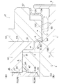
環状部材に環状プレートを同軸に圧入嵌合するための圧入治具であって、
前記環状部材は固定軸の周りに同軸に固定され、前記固定軸は、その軸方向前方に位置する前端面に中心穴を同軸に有し、
前記環状部材は、その前端面に第1円筒面を同軸に有し、
前記環状プレートは、その中心部に第2円筒面を同軸に有し、
前記圧入治具は、前記第2円筒面を前記第1円筒面の周りに同軸に圧入嵌合するよう適用され、
前記圧入治具は、
前記固定軸の前記中心穴に挿入される芯決めピンと、
前記芯決めピンの周りに嵌合されるガイド軸と、
前記ガイド軸の周りに軸方向スライド可能に配置され、前記環状プレートにおける前記第2円筒面の周囲の部分を押圧するように構成された圧入具と、を備える
ことを特徴とする圧入治具が提供される。
前記圧入治具は、前記圧入具を伸長方向に付勢する付勢部材を有する。
2 カウンタ軸
3 環状プレート
6 中心穴
8 第1円筒面
10 第2円筒面
10C 周囲部分
40 圧入治具
41 芯決めピン
42 ガイド軸
43 圧入具
60 スプリング
Claims (4)
- 環状部材に環状プレートを同軸に圧入嵌合するための圧入治具であって、
前記環状部材は固定軸の周りに同軸に固定され、前記固定軸は、その軸方向前方に位置する前端面に中心穴を同軸に有し、
前記環状部材は、その前端面に第1円筒面を同軸に有し、
前記環状プレートは、その中心部に第2円筒面を同軸に有し、
前記圧入治具は、前記第2円筒面を前記第1円筒面の周りに同軸に圧入嵌合するよう適用され、
前記圧入治具は、
前記固定軸の前記中心穴に挿入される芯決めピンと、
前記芯決めピンの周りに嵌合されるガイド軸と、
前記ガイド軸の周りに軸方向スライド可能に配置され、前記環状プレートにおける前記第2円筒面の周囲の部分を押圧するように構成された圧入具と、を備える
ことを特徴とする圧入治具。 - 前記中心穴が、前記固定軸の機械加工時に形成されるセンタ穴である
ことを特徴とする請求項1に記載の圧入治具。 - 前記圧入具は、前記ガイド軸に離脱不能に連結されると共に、前記ガイド軸に対し伸縮可能に連結され、
前記圧入治具は、前記圧入具を伸長方向に付勢する付勢部材を有する
ことを特徴とする請求項1または2に記載の圧入治具。 - 前記環状部材は、車両用変速機のハブであり、前記固定軸は、前記車両用変速機の回転軸である
ことを特徴とする請求項1〜3のいずれか一項に記載の圧入治具。
Priority Applications (1)
| Application Number | Priority Date | Filing Date | Title |
|---|---|---|---|
| JP2016090523A JP6662183B2 (ja) | 2016-04-28 | 2016-04-28 | 圧入治具 |
Applications Claiming Priority (1)
| Application Number | Priority Date | Filing Date | Title |
|---|---|---|---|
| JP2016090523A JP6662183B2 (ja) | 2016-04-28 | 2016-04-28 | 圧入治具 |
Publications (2)
| Publication Number | Publication Date |
|---|---|
| JP2017196708A true JP2017196708A (ja) | 2017-11-02 |
| JP6662183B2 JP6662183B2 (ja) | 2020-03-11 |
Family
ID=60237035
Family Applications (1)
| Application Number | Title | Priority Date | Filing Date |
|---|---|---|---|
| JP2016090523A Active JP6662183B2 (ja) | 2016-04-28 | 2016-04-28 | 圧入治具 |
Country Status (1)
| Country | Link |
|---|---|
| JP (1) | JP6662183B2 (ja) |
-
2016
- 2016-04-28 JP JP2016090523A patent/JP6662183B2/ja active Active
Also Published As
| Publication number | Publication date |
|---|---|
| JP6662183B2 (ja) | 2020-03-11 |
Similar Documents
| Publication | Publication Date | Title |
|---|---|---|
| CN104806634B (zh) | 衬套轴承的结构 | |
| US11465671B2 (en) | Method for the production of electric power steering systems as well as an electric power steering system | |
| CN105864300B (zh) | 用于围绕轴承的外环组装夹具的方法 | |
| JP2015124875A (ja) | 差動装置の製造方法 | |
| JP2006064179A (ja) | トルクリング継手を有する駆動軸アセンブリ | |
| TWI696558B (zh) | 用於腳踏車的輪轂 | |
| JP6000057B2 (ja) | 車両用手動変速機の同期装置 | |
| US7093701B2 (en) | Bridging clutch for a clutch apparatus which has a hydrodynamic circuit in a clutch housing | |
| KR101551069B1 (ko) | 차량용 휠의 구동력 전달장치 | |
| JP2017196708A (ja) | 圧入治具 | |
| JP5978647B2 (ja) | 十字軸式自在継手 | |
| JP2017514078A (ja) | 自動車用のトルク伝達装置 | |
| JP2009148864A (ja) | 工具ホルダ | |
| US20160273638A1 (en) | Method of attaching ring gear to differential case, jig, and differential case | |
| US11738427B1 (en) | Ring mounting jig and ring mounting method | |
| JP2018141506A (ja) | 締結構造、締結方法、及びハイブリッド車両用駆動装置 | |
| JP6331678B2 (ja) | 十字軸式自在継手の組立方法 | |
| JP2013057380A (ja) | 摺動式スプライン軸装置およびその製造方法 | |
| JP2013245708A (ja) | スプリング固定装置 | |
| KR101570766B1 (ko) | 휠 허브 및 그 제조방법 | |
| US12000440B2 (en) | Torsionally elastic shaft joint and method of making the same | |
| JP5772418B2 (ja) | 摺動式スプライン軸装置およびその製造方法 | |
| KR101689839B1 (ko) | 휠 베어링 및 이를 사용한 휠 베어링 조립체 | |
| US11796002B2 (en) | Bearing arrangement for a machine element | |
| JP2014202246A (ja) | 車両用変速機の同期装置 |
Legal Events
| Date | Code | Title | Description |
|---|---|---|---|
| A521 | Written amendment |
Free format text: JAPANESE INTERMEDIATE CODE: A821 Effective date: 20160428 |
|
| A621 | Written request for application examination |
Free format text: JAPANESE INTERMEDIATE CODE: A621 Effective date: 20190327 |
|
| A977 | Report on retrieval |
Free format text: JAPANESE INTERMEDIATE CODE: A971007 Effective date: 20191111 |
|
| A131 | Notification of reasons for refusal |
Free format text: JAPANESE INTERMEDIATE CODE: A131 Effective date: 20191119 |
|
| A521 | Written amendment |
Free format text: JAPANESE INTERMEDIATE CODE: A821 Effective date: 20200108 Free format text: JAPANESE INTERMEDIATE CODE: A523 Effective date: 20200108 |
|
| TRDD | Decision of grant or rejection written | ||
| A01 | Written decision to grant a patent or to grant a registration (utility model) |
Free format text: JAPANESE INTERMEDIATE CODE: A01 Effective date: 20200114 |
|
| A61 | First payment of annual fees (during grant procedure) |
Free format text: JAPANESE INTERMEDIATE CODE: A61 Effective date: 20200127 |
|
| R150 | Certificate of patent or registration of utility model |
Ref document number: 6662183 Country of ref document: JP Free format text: JAPANESE INTERMEDIATE CODE: R150 |