JP2017197345A - Laying unit for belt conveyor, and belt conveyor using the same - Google Patents
Laying unit for belt conveyor, and belt conveyor using the same Download PDFInfo
- Publication number
- JP2017197345A JP2017197345A JP2016089794A JP2016089794A JP2017197345A JP 2017197345 A JP2017197345 A JP 2017197345A JP 2016089794 A JP2016089794 A JP 2016089794A JP 2016089794 A JP2016089794 A JP 2016089794A JP 2017197345 A JP2017197345 A JP 2017197345A
- Authority
- JP
- Japan
- Prior art keywords
- unit
- belt conveyor
- return
- belt
- transport
- Prior art date
- Legal status (The legal status is an assumption and is not a legal conclusion. Google has not performed a legal analysis and makes no representation as to the accuracy of the status listed.)
- Granted
Links
Images


Landscapes
- Excavating Of Shafts Or Tunnels (AREA)
- Structure Of Belt Conveyors (AREA)
Abstract
Description
本発明は、ベルトコンベアに係り、特に、搬送区間が描く搬送経路の線形形状に沿って無端状の搬送ベルトが張設されるベルトコンベアに好適に用いることができる技術に関する。 The present invention relates to a belt conveyor, and more particularly to a technique that can be suitably used for a belt conveyor in which an endless conveyance belt is stretched along a linear shape of a conveyance path drawn by a conveyance section.
搬送区間中に曲線区間を有するベルトコンベア(以下、「曲送コンベア」ともいう)としては、例えば、特許文献1ないし2に記載の技術が開示されている。特許文献1ないし2に記載の曲送コンベアは、個別の支持フレームに設けられたキャリアローラ(およびリターンローラ)の組が、搬送経路の線形に沿って多数配置される。
As a belt conveyor having a curved section in a transport section (hereinafter, also referred to as “curved feeding conveyor”), for example, techniques disclosed in
しかしながら、特許文献1ないし2に記載の曲送コンベアでは、多数の支持フレーム毎に基礎工事を要する。また、工事規模に相応して周囲に広い作業スペースが必要となる。例えば、曲送コンベアを「道路」に併設するなど、延長距離が長いほどこの問題点が顕著となる。
そこで、本発明は、このような問題点に着目してなされたものであって、簡単な基礎工事で施工でき、その後の撤去も容易且つ迅速に行えるベルトコンベア用敷設ユニットおよびこれを用いたベルトコンベアを提供することを課題とする。
However, the curved conveyor described in
Therefore, the present invention has been made paying attention to such problems, and can be constructed by simple foundation work, and can be easily and quickly removed thereafter, and a belt using the same. It is an object to provide a conveyor.
上記課題を解決するために、本発明の一態様に係るベルトコンベア用敷設ユニットは、搬送経路の線形形状に沿って無端状の搬送ベルトが張設されるベルトコンベアに用いられ、搬送区間の途中部分を区分して前記ベルトコンベアを構築するための敷設ユニットであって、上下に区画されて上部階および下部階の二階層を有するとともに、自身長手方向を搬送方向とするように構成された筐体と、前記筐体の上部階に前記長手方向に沿って配置された複数の往路用支持フレームと、各往路用支持フレームにそれぞれ設置された複数のキャリアローラと、前記筐体の下部階に前記長手方向に沿って配置された複数の復路用支持フレームと、各復路用支持フレームにそれぞれ設置された複数のリターンローラと、を備えることを特徴とする。 In order to solve the above problems, a belt conveyor laying unit according to one aspect of the present invention is used in a belt conveyor in which an endless conveyance belt is stretched along a linear shape of a conveyance path, and is in the middle of a conveyance section. A laying unit for constructing the belt conveyor by dividing a section, which is divided into upper and lower floors and has two layers of an upper floor and a lower floor, and is configured so that its own longitudinal direction is a transport direction. A body, a plurality of forward support frames arranged along the longitudinal direction on the upper floor of the housing, a plurality of carrier rollers respectively installed on each forward support frame, and a lower floor of the housing It is characterized by comprising a plurality of return path support frames arranged along the longitudinal direction and a plurality of return rollers respectively installed on each return path support frame.
本発明の一態様に係るベルトコンベア用敷設ユニットによれば、上下に二階層構造の筐体を有し、上部階に複数の往路用支持フレームを設けてそれぞれに複数のキャリアローラを配し、下部階に複数の復路用支持フレームを設けてそれぞれに複数のリターンローラを配したので、個別の支持フレームを多数施工する場合と比べて、敷設ユニット単位の基礎工事でベルトコンベアを施工できることから、工事の簡素化が可能である。また、その後の撤去作業も敷設ユニット単位で可能なので、撤去作業も容易且つ迅速に行える。 According to the belt conveyor laying unit according to one aspect of the present invention, the housing has a two-layered structure on the top and bottom, a plurality of support frames for the forward path are provided on the upper floor, and a plurality of carrier rollers are arranged on each, Since a plurality of return frames are provided on the lower floor and a plurality of return rollers are arranged for each, it is possible to construct a belt conveyor by foundation work for each laying unit compared to the case of constructing a large number of individual support frames. Construction can be simplified. Further, since the subsequent removal work can be performed in units of laying units, the removal work can be performed easily and quickly.
特に、本発明の一態様に係るベルトコンベア用敷設ユニットは、上下二階層のコンパクトな構造なので、例えば、トンネルを含む既設の高速道路に沿ってベルトコンベアを限定された空間で敷設する場合などに好適である。
ここで、本発明の一態様に係るベルトコンベア用敷設ユニットにおいて、各往路用支持フレームにそれぞれ設置された前記複数のキャリアローラは、横断面視において、前記搬送ベルトの周方向への移動を許容するように前記搬送ベルトをトラフ状に支持する構造であり、各往路用支持フレームにそれぞれ設置された前記複数のリターンローラは、横断面視において、復路側で巻回された前記搬送ベルトをパイプ状に支持する構造であることは好ましい。
In particular, the belt conveyor laying unit according to one aspect of the present invention has a compact structure of two levels up and down, for example, when the belt conveyor is laid in a limited space along an existing highway including a tunnel. Is preferred.
Here, in the belt conveyor laying unit according to one aspect of the present invention, the plurality of carrier rollers respectively installed in each forward path support frame allow the conveyance belt to move in the circumferential direction in a cross-sectional view. The plurality of return rollers installed on each forward support frame are piped around the conveyor belt wound on the return path side in a cross-sectional view. It is preferable that the structure is supported in a shape.
このような構成であれば、キャリアローラは、搬送ベルトをトラフ状に支持し、搬送ベルトの周方向への移動を許容することができる。そのため、例えば搬送区間に曲線区間を含む場合であっても、曲線区間を曲送時のバンク範囲に応じ、搬送区間が描く搬送経路の線形形状に沿って無端状の搬送ベルトが張設されるベルトコンベア用として好適である。また、リターンローラは、復路側で巻回された搬送ベルトをパイプ状に支持する構造なので、搬送面に土砂等の一部が付着したまま往路に戻る場合であっても、戻り経路途中での落下を確実に防止する上で好適である。 With such a configuration, the carrier roller can support the transport belt in a trough shape and allow movement of the transport belt in the circumferential direction. Therefore, for example, even when the conveyance section includes a curved section, an endless conveyance belt is stretched along the linear shape of the conveyance path drawn by the conveyance section according to the bank range when the curved section is bent. Suitable for belt conveyors. In addition, the return roller has a structure that supports the conveyor belt wound on the return path side in a pipe shape, so even when returning to the forward path with a part of the earth and sand adhering to the transport surface, It is suitable for reliably preventing the fall.
また、上記課題を解決するために、本発明の一態様に係るベルトコンベアは、搬送経路の線形形状に沿って無端状の搬送ベルトが張設されるベルトコンベアであって、本発明のいずれか一の態様に係るベルトコンベア用敷設ユニットを複数個用いて構成されていることを特徴とする。
本発明の一態様に係るベルトコンベアによれば、本発明のいずれか一の態様に係るベルトコンベア用敷設ユニットを複数個用いて構成されているので、本発明のいずれか一の様に係るベルトコンベア用敷設ユニットが奏する作用効果により、ベルトコンベアを簡単な基礎工事で施工でき、その後の撤去も容易且つ迅速に行える。
In order to solve the above problem, a belt conveyor according to one aspect of the present invention is a belt conveyor in which an endless conveyance belt is stretched along a linear shape of a conveyance path, and any one of the present invention It is configured using a plurality of belt conveyor laying units according to one aspect.
According to the belt conveyor according to one aspect of the present invention, the belt conveyor according to any one aspect of the present invention is configured by using a plurality of belt conveyor laying units according to any one aspect of the present invention. Due to the effects of the conveyor laying unit, the belt conveyor can be constructed by simple foundation work, and the subsequent removal can be performed easily and quickly.
ここで、本発明の一態様に係るベルトコンベアにおいて、前記敷設ユニットは、前記中央分離帯を挟む一方側の道路または他方側の道路に沿って設置される標準ユニットであることは好ましい。さらに、前記標準ユニットは、各往路用支持フレームにそれぞれ設置された前記複数のキャリアローラの搬送中心が、前記長手方向に沿った一直線上に配置され、各復路用支持フレームにそれぞれ設置された前記複数のリターンローラの搬送中心が、前記複数のキャリアローラの搬送中心に対して前記下部階の左右のいずれか一方に偏倚した位置に配置され、前記下部階は、各往路用支持フレームにそれぞれ設置された前記複数のリターンローラの偏倚した側と反対の側が作業通路になっていることは好ましい。このような構成であれば、作業通路によってメンテナンス等の作業性が向上する。そのため、例えば、トンネルを含む既設の高速道路に沿ってベルトコンベアを限定された空間で敷設する場合などにより好適である。 Here, in the belt conveyor according to one aspect of the present invention, it is preferable that the laying unit is a standard unit installed along one road or the other road sandwiching the central separation band. Further, the standard unit is configured such that the transport centers of the plurality of carrier rollers respectively installed on the forward support frames are arranged on a straight line along the longitudinal direction, and are installed on the return support frames, respectively. The transport centers of the plurality of return rollers are arranged at positions shifted to either the left or right of the lower floor with respect to the transport centers of the plurality of carrier rollers, and the lower floor is installed on each forward support frame. It is preferable that the side opposite to the biased side of the plurality of return rollers is a work path. With such a configuration, workability such as maintenance is improved by the work passage. Therefore, for example, it is more suitable when a belt conveyor is laid in a limited space along an existing highway including a tunnel.
また、本発明の一態様に係るベルトコンベアにおいて、前記標準ユニットと共に用いられる他のベルトコンベア用敷設ユニットとして、前記中央分離帯の上方の位置に当該中央分離帯に沿って設置される跨設ユニットと、前記標準ユニットと前記跨設ユニットとの間を繋ぐ連結ユニットとを更に備えることは好ましい。
このような構成であれば、道路が停車帯を有する場合であっても、停車帯のある箇所で、中央分離帯を挟む一方側の道路の部分から他方側の道路の部分に、中央分離帯の上方の位置を跨いでベルトコンベアを敷設できる。そのため、例えば、道路が高速道路の場合に、所定距離毎に停車帯を設ける上で好適である。
Moreover, in the belt conveyor which concerns on 1 aspect of this invention, as the installation unit for other belt conveyors used with the said standard unit, the extending | stretching unit installed along the said central separation belt in the position above the said central separation belt And a connecting unit that connects between the standard unit and the straddling unit.
With such a configuration, even if the road has a stop zone, the center zone is changed from the portion of the road on one side to the portion of the other side of the road where the stop zone is located. A belt conveyer can be laid across the position above. Therefore, for example, when the road is an expressway, it is suitable for providing a stop zone for each predetermined distance.
また、前記跨設ユニットは、自身長手方向を搬送方向として前記中央分離帯の上方の位置に一の区画のみを構成する一階層構造の筐体を備え、当該筐体の床面上には、前記長手方向に沿って配置された複数の復路用支持フレームと、各復路用支持フレームにそれぞれ設置された複数のキャリアローラと、各復路用支持フレームの上部にそれぞれが載置固定された複数の往路用支持フレームと、各往路用支持フレームにそれぞれ設置されて搬送中心が前記筐体の長手方向に沿った一直線上に配置される複数のキャリアローラとを有することは好ましい。このような構成であれば、停車帯で中央分離帯の上方の位置に設置される跨設ユニットをコンパクトに構成する上で好適である。 In addition, the straddling unit includes a one-layered housing that constitutes only one section at a position above the median strip with the longitudinal direction as the transport direction, on the floor surface of the housing, A plurality of return path support frames arranged along the longitudinal direction, a plurality of carrier rollers respectively installed on each return path support frame, and a plurality of fixed rollers mounted on and fixed to the upper part of each return path support frame, respectively. It is preferable to have a forward support frame and a plurality of carrier rollers that are installed on each forward support frame and whose transport center is arranged in a straight line along the longitudinal direction of the casing. Such a configuration is suitable for compactly configuring the straddling unit installed at a position above the central separation zone in the stop zone.
また、前記連結ユニットは、上下に区画されて上部階および下部階の二階層を有するとともに、自身長手方向を搬送方向とするように構成された筐体と、前記筐体の上部階に前記長手方向に沿って配置された複数の往路用支持フレームと、各往路用支持フレームにそれぞれ設置された複数のキャリアローラと、前記筐体の下部階に前記長手方向に沿って配置された複数の復路用支持フレームと、各復路用支持フレームにそれぞれ設置された複数のリターンローラとを備え、各往路用支持フレームにそれぞれ設置された前記複数のキャリアローラの搬送中心が、前記筐体の長手方向に沿った一直線上に配置され、各復路用支持フレームにそれぞれ設置された前記複数のリターンローラが、前記複数のキャリアローラの搬送中心に対して前記下部階の左右のいずれか一方からいずれか他方へと偏倚した位置を入れ替えるように配置されることは好ましい。このような構成であれば、停車帯で搬送ベルトの幅方向での搬送位置を変える際に、復路における搬送ベルトの幅方向での搬送位置を円滑に変更する上で好適である。 In addition, the connection unit is divided into upper and lower floors and has two levels of an upper floor and a lower floor, and a casing configured to have the longitudinal direction as a transport direction, and the longitudinal direction on the upper floor of the casing A plurality of forward support frames arranged along the direction, a plurality of carrier rollers respectively installed on each forward support frame, and a plurality of return paths arranged along the longitudinal direction on the lower floor of the housing And a plurality of return rollers respectively installed on each return path support frame, and the transport centers of the plurality of carrier rollers respectively installed on each forward path support frame are in the longitudinal direction of the casing. The plurality of return rollers arranged on a straight line along each of the return path support frames are arranged on the lower portion with respect to the transport center of the plurality of carrier rollers. It is arranged from one of the left and right to switch the position offset to the other one it is preferable. Such a configuration is suitable for smoothly changing the conveyance position in the width direction of the conveyance belt in the return path when changing the conveyance position in the width direction of the conveyance belt in the stop zone.
上述のように、本発明によれば、ベルトコンベアを簡単な基礎工事で施工でき、その後の撤去も容易且つ迅速に行える。 As described above, according to the present invention, the belt conveyor can be constructed by simple foundation work, and the subsequent removal can be easily and quickly performed.
以下、本発明の一実施形態について、図面を適宜参照しつつ説明する。ここで、本実施形態のベルトコンベアは、トンネル工事による土砂の採掘現場に連接される、総延長が数キロメートルの長大な設備であり、採掘現場からの掘削土砂等の被搬送物の搬送に使用される例である。
なお、図面は模式的なものである。そのため、厚みと平面寸法との関係、比率等は現実のものとは異なることに留意すべきであり、図面相互間においても互いの寸法の関係や比率が異なる部分が含まれている。また、以下に示す実施形態は、本発明の技術的思想を具体化するための装置や方法を例示するものであって、本発明の技術的思想は、構成部品の材質、形状、構造、配置等を下記の実施形態に特定するものではない。
Hereinafter, an embodiment of the present invention will be described with reference to the drawings as appropriate. Here, the belt conveyor of this embodiment is a long facility with a total length of several kilometers connected to the earth and sand mining site by tunnel construction, and is used for transporting objects to be conveyed such as excavated earth and sand from the mining site. This is an example.
The drawings are schematic. For this reason, it should be noted that the relationship between the thickness and the planar dimension, the ratio, and the like are different from the actual ones, and the dimensional relationship and the ratio are different between the drawings. Further, the following embodiments exemplify apparatuses and methods for embodying the technical idea of the present invention, and the technical idea of the present invention is the material, shape, structure, and arrangement of components. Etc. are not specified in the following embodiments.
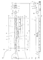
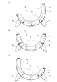
図1に示すように、このベルトコンベア1は、トンネル工事を含む道路工事現場に連接される既設の道路Mに沿って設置される。道路Mは、複数の走行車線Lと中央分離帯Sとを有する。ベルトコンベア1は、複数の走行車線Lのうち、最も中央分離帯S寄りの一車線を用いて敷設される。そのため、基本的には、道路Mの線形形状がベルトコンベア1の搬送経路と一致する。また、ベルトコンベア1の搬送区間Hは、曲線区間Rを含んで構成される。そのため、本実施形態では、曲線的な搬送が可能なベルトコンベア(以下、「曲送コンベア」ともいう)が敷設される。
As shown in FIG. 1, the
詳しくは、この曲送コンベア1は、同図に示すように、搬送経路の先端に配置される円筒状のヘッダローラ3と、尾端に配置される円筒状のフッタローラ4と、無端状の搬送ベルト2とを有する。搬送ベルト2は、搬送経路の線形形状に沿ってヘッダローラ3およびフッタローラ4間に掛け回される。
搬送ベルト2は、積層構造をもつ帯状部材であり、搬送方向で複数に分割された複数のベルト素材を繋ぎ合わせて無端状に形成される。各ベルト素材は、以下不図示の、幅方向に多条に埋設される補強用の線状心材であるコードと、コードの周囲に充填される中間ゴム層と、中間ゴム層の表面及び裏面に積層される耐摩耗性のカバーゴム層とを有する。搬送ベルト2は、複数のベルト素材相互の端部を現場で加硫接合して無端状に形成される。
Specifically, as shown in the figure, the
The
ヘッダローラ3側は、搬送元から搬送先に向かうにつれて斜め上方に向かうように傾斜配置されている。これにより、ヘッダローラ3側の設備は、道路Mから上方に離隔した位置に施設されている。ヘッダローラの下側には、駆動装置7が付設された4つの駆動ローラ5が配置されている。また、ヘッダローラ3の下方には、掘削土砂等の被搬送物を投下できるようにホッパ6が設けられている。なお、被搬送物が投下されるイメージを符号Gを付した白抜き矢印で示している。
The header roller 3 side is inclined so as to go obliquely upward as it goes from the transport source to the transport destination. As a result, the equipment on the header roller 3 side is provided at a position spaced upward from the road M. Below the header roller, four driving
フッタローラ4側は、既設の道路Mとその関連設備に干渉しないように、道路Mの上下線の分岐位置を利用して施設されている。フッタローラ4側には、以下不図示の、搬送ベルト2の張設機構、カウンタウエイトおよび洗浄装置等の設備が配置される。さらに、フッタローラ4側には、被搬送物を搬送ベルト2上に投入する投入装置が、例えば搬送方向の二カ所に配置されている(同図(b)の白抜き矢印Fの位置)。なお、この例では、フッタローラ4にも搬送ベルト2を駆動する駆動装置7が付設されている。
The
ここで、この曲送コンベア1は、同図(b)に示すように、搬送ベルト2の途中部分を、道路Mに沿って案内する複数の敷設ユニット10を備える。複数の敷設ユニット10は、同図(a)に示す平面視において、搬送経路となる道路Mの線形形状に沿って、その線形形状に近似する多角形の外周の一部を、搬送中心を結ぶ直線が描くように配置される。
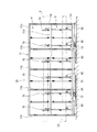
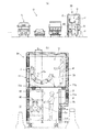
特に、本実施形態の曲送コンベア1は、図2に拡大図示するように、複数の敷設ユニット10として、標準ユニット20、連結ユニット30、40、および跨設ユニット50を備えている。これらの敷設ユニット10は、曲線区間Rを含む搬送区間Hが描く搬送経路の線形形状に沿って適切な敷設ユニット10が選択的に敷設される。
Here, the
In particular, the
本実施形態では、標準ユニット20は、中央分離帯Sを挟む一方側の道路Mおよび他方側の道路Mに沿って設置される。跨設ユニット50は、中央分離帯Sの上方の位置に、当該中央分離帯Sを跨ぐように設置される。連結ユニット30、40は、標準ユニット20と跨設ユニット50との間を繋ぐ位置に設置される。
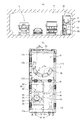
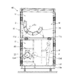
標準ユニット20は、図3に示すように、自身長手方向を搬送方向とするように構成された筐体11を有する。筐体11は、形鋼(H形鋼、等辺山形鋼、溝形鋼等)を用いて、溶接およびボルト・ナット締結により形鋼を直方体状に構築した枠体である。筐体11は、自身長手方向を搬送方向とする長方形状の基台11aと、基台11aの四隅および長辺の適所に立設された複数の支柱11bと、複数の支柱11bの上端部相互を繋ぐ複数の梁11cと、複数の支柱11bの中間部相互を繋ぐ複数の胴差11dとを有する。
In this embodiment, the
As shown in FIG. 3, the
基台11aの下部には、筐体11の前後に離隔して、車輪12が左右に計4箇所設けられている。一方、道路Mには、ベルトコンベア1が敷設される位置に、二条のレール91が敷設される。二条のレール91は、道路Mの線形形状に沿って道路M上に平行に敷設される。これにより、標準ユニット20は、下部の車輪12により、左右一対のレール91上を走行可能になっている。
At a lower part of the
本実施形態の筐体11は、複数の支柱11bの略中間部分設けた胴差11dにより筐体11が上下に区画されている。これにより、標準ユニット20には、上部階Uおよび下部階Dの二階層が構築されている。筐体11の上部階Uには、複数のキャリアローラ組70が設置される。キャリアローラ組70は、搬送ベルト2を下方から支持しつつ搬送方向に沿って往路側で案内するためのベルト案内装置である。キャリアローラ組70は、各筐体11に対して、筐体11の長手方向に沿って所定間隔を隔てて複数組が上部階Uに配置される。
In the
さらに、筐体11の下部階Dには、複数のリターンローラ組80が設置される。複数のリターンローラ組80は、筐体11の長手方向に沿って搬送ベルト2を往路側で案内するように配置される。
図4に示すように、基台11aの上面と胴差11dの上面には、作業者Pの作業通路Wとする場合に、作業通路Wに対応する箇所に、作業者Pが歩行可能なように、パンチングメタル等を床板に用いた床面11fが設けられる。
Further, a plurality of return roller sets 80 are installed on the lower floor D of the
As shown in FIG. 4, when the work path W of the worker P is provided on the upper surface of the
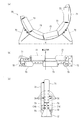
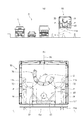
各キャリアローラ組70は、図5に示すように、上方に向けた半円弧状の支持フレーム71と、支持フレーム71の外周面の左右にボルト・ナットで着脱可能に設けられた一対の支持脚72と、支持フレーム71の内周面に沿って半円弧状に配置された複数のキャリアローラ73とを有する。
各キャリアローラ73は、円筒状をなす案内ローラであり、両端部が自身軸回りに回転自在に支持されている。複数のキャリアローラ73は、同図(b)に示すように、搬送方向に対して前側と後側との二段に配置される。さらに、複数のキャリアローラ73は、支持フレーム71の周方向で隣接するキャリアローラ73相互が前後で互い違いに配置される。
As shown in FIG. 5, each carrier roller set 70 includes a semicircular arc-shaped
Each
各キャリアローラ組70は、複数のキャリアローラ73相互の協働により、搬送ベルト2を下方から半円弧状の湾曲状態に支持しつつ搬送方向に沿って案内可能に設置される。これにより、図1に示す曲線区間Rにおいて、各支持フレーム71にそれぞれ設置された複数のキャリアローラ73は、搬送ベルト2を曲送時のバンク範囲で、横断面視において、搬送ベルト2の周方向への移動を許容するように搬送ベルト2をトラフ状に支持可能になっている。
Each carrier roller set 70 is installed so that it can be guided along the conveyance direction while supporting the
さらに、本実施形態のキャリアローラ組70は、道路Mの線形に応じた搬送ベルト2の搬送姿勢を調整するために複数の姿勢を設定可能になっている。つまり、支持フレーム71は、図5(c)に示すように、複数組の搬送姿勢調整穴74を有する。搬送姿勢調整穴74は、ボルト・ナットを締結可能に形成され、支持フレーム71の周方向に沿って複数箇所に設けられている。キャリアローラ組70は、複数組の搬送姿勢調整穴74を用いることにより、一対の支持脚72に対する半円弧状の支持フレーム71の周方向での締結位置を複数の位置に変更できる。これにより、例えば図6(a)〜(c)に示すように、支持フレーム71の傾斜姿勢(搬送路の曲率に応じたバンク角度)を、線形に応じた傾斜姿勢に変更可能になっている。
Further, the carrier roller set 70 of the present embodiment can be set in a plurality of postures in order to adjust the transport posture of the
ここで、搬送ベルト2の幅方向の長さは、被搬送物Kおよび搬送ベルト2に作用する遠心力を考慮して、複数のキャリアローラ73全体による内周側の支持曲面の展開長よりも短く設定されている。これにより、設置箇所での曲率やバンク角に応じて搬送ベルト2が周方向の外側に移動した場合であっても、複数のキャリアローラ73全体による確実な支持が行えるようになっている。なお、図6(a)は同図右側へ最大傾斜、(b)は中央、(c)は同図左側へ最大傾斜となる位置に、支持フレーム71を装着した状態をそれぞれ示すとともに、各図において、二点鎖線は搬送ベルト2、一点鎖線は被搬送物Kのイメージをそれぞれ示している。
Here, the length of the
リターンローラ組80は、図3に示すように、搬送ベルト2を復路側で案内するためのベルト案内装置である。リターンローラ組80は、各筐体11に対して、筐体11の長手方向に沿って所定間隔を隔てて複数組が配置され、筐体11の長手方向に沿って搬送ベルト2を復路側で案内するように設置される。リターンローラ組80は、図4(b)に示すように、横断面視において、円筒状(パイプ状)に巻回された搬送ベルト2を周方向の3方から支持しつつ搬送方向に沿って案内する。
As shown in FIG. 3, the return roller set 80 is a belt guide device for guiding the
各リターンローラ組80は、図4(b)に示すように、巻回された搬送ベルト2を囲繞する矩形枠状の支持フレーム81を有する。支持フレーム81は、筐体11の内側面に支持枠82を介してボルト・ナットで着脱可能に固定される。支持フレーム81の内側面には、複数のリターンローラ83が装着される。各リターンローラ83は、円筒状をなす案内ローラであり、両端部が自身軸回りに回転自在に支持されている。
As shown in FIG. 4B, each return roller set 80 has a rectangular frame-shaped
複数のリターンローラ83は、円筒状に巻回された搬送ベルト2を支持するために、周方向に離隔して等配されている。本実施形態では、円筒状に巻回された搬送ベルト2の上部の一箇所と、周方向で120°離隔した下部の二箇所の、計三箇所にリターンローラ83が配置されている。これにより、各支持フレーム81にそれぞれ設置された複数のリターンローラ83は、相互の協働により、搬送ベルト2を周方向の3方から円筒状(パイプ状)の巻回状態に支持しつつ搬送方向に沿って案内可能になっている。
The plurality of
ここで、敷設ユニット10のうち、標準ユニット20の場合は、上部階Uのキャリアローラ組70の幅方向の最大寸法V(図5(a)参照)が、図4(b)に示すように、筐体11の内法寸法にほぼ等しく設定されている。そのため、同図に示すように、上部階Uの幅方向の中央CLと、半円弧状に配置された複数のキャリアローラ73の搬送中心Cuとが略一致している。これにより、各支持フレーム71にそれぞれ設置された複数のキャリアローラ73による搬送中心Cuは、筐体11の長手方向に沿った一直線上に並ぶように配置される。
Here, in the case of the
これに対し、下部階Dは、リターンローラ組80が、一方側に偏倚した位置に設置される。そのため、同図に示すように、キャリアローラ組70の搬送中心Cuに対して、リターンローラ組80の複数のリターンローラ83による搬送中心Cdが一方側に偏倚している。換言すれば、各支持フレーム81にそれぞれ設置された複数のリターンローラ83は、往路側の複数のキャリアローラ73の搬送中心Cuに対して下部階Dの左右のいずれかに偏倚量Exだけ偏倚した位置に配置される。
On the other hand, the lower floor D is installed at a position where the return roller set 80 is biased to one side. Therefore, as shown in the figure, the transport center Cd by the plurality of
これにより、下部階Dは、リターンローラ組80とは反対の側が、作業者Pが歩行可能な作業通路Wを設定になっており、作業通路Wとして使用する場合には、基台11a上面の作業通路Wとすべき部分に床面11fが設けられる。標準ユニット20の場合は、上部階Uには床面が設けられていない。
次に、連結ユニット30、40および跨設ユニット50について説明する。なお、上述した標準ユニット20以外の他の敷設ユニット10については、特に言及しない限りは、標準ユニット20と共通する構成を有する。そのため、共通する構成については同一の符号を付すとともにその説明は適宜省略する。
As a result, the lower floor D has a work path W on which the operator P can walk on the opposite side of the return roller set 80. When the lower floor D is used as the work path W, the upper surface of the
Next, the
ここで、道路Mが高速道路の場合、法令上、図1に示すように、所定距離毎に停車帯Nを設ける必要がある。そのため、この停車帯Nを設ける位置では、走行車線Lを曲送コンベア1の敷設に用いることができない。換言すれば、停車帯Nを設ける位置では、単純に道路Mの線形形状に沿って曲送コンベア1を敷設できない。
そこで、本実施形態では、敷設ユニット10として、標準ユニット20の他に、連結ユニット30、40および跨設ユニット50を用意しており、これらの組み合わせによって、図2に示すように、中央分離帯Sの上部および対向車線を利用して曲送コンベア1を敷設している。特に、本実施形態では、連結ユニットとして、オープンユニット30および特殊ユニット40を用意している。
Here, when the road M is an expressway, it is necessary to provide a stop zone N for each predetermined distance as shown in FIG. Therefore, at the position where the stop zone N is provided, the traveling lane L cannot be used for laying the
Therefore, in the present embodiment, as the laying
詳しくは、連結ユニットのうちオープンユニット30は、解放区間Oに設置される敷設ユニットであって、図7に示すように、筐体11下部側の基台11aは標準ユニット20と同じものを用いているため、下部の幅寸法については標準ユニット20と同じ寸法である。しかし、下部階Dの略中央から上部の部分に拡幅部Ewを有する点が異なっている。オープンユニット30は、拡幅部Ewを有することにより、下部階Dの略中央から上部の部分が、標準ユニット20よりも幅方向の寸法が広くなっている。
Specifically, among the connecting units, the
オープンユニット30は、拡幅部Ewにより幅方向に広げた拡幅領域を利用して、上部階Uにも、キャリアローラ組70の側方に、作業者Pが歩行可能なように、パンチングメタル等を床板に用いた床面11gが設けられる。また、オープンユニット30は、下部階Dと上部階Uとの間を移動可能な階段Stを設置できる。これにより、オープンユニット30は、道路Mのトンネル(カルバート)区間Tを除く解放区間Oに敷設する上で好適であり、拡幅領域を利用して設置した階段により、下部階Dから上部階Uに続く作業通路Wを容易に構築できる。
The
また、連結ユニットのうち特殊ユニット40は、図8に示すように、筐体11下部の基台11w(および胴差11d)は、標準ユニット20よりも幅方向に長いものを用いているため、筐体11の幅方向の寸法が、標準ユニット20よりも全体的に広くなっている点が標準ユニット20とは異なっている。特殊ユニット40は、標準ユニット20に対して、筐体11の幅寸法が上記拡幅部Ewの分だけ広くなっている。
In addition, as shown in FIG. 8, the
これにより、特殊ユニット40は、筐体11を幅方向に広げた拡幅領域を利用して、作業通路Wを上部階Uおよび下部階Dともに確保できる。さらに、特殊ユニット40は、拡幅領域を利用して、複数のリターンローラ組80の偏倚量Exを、必要な曲率に合わせて筐体11の幅方向に順次に変えるように設置される。
特に、停車帯Nで搬送方向を変える際に、特殊ユニット40は、往路用の各支持フレーム71にそれぞれ設置された複数のキャリアローラ73の搬送中心Cuについては、標準ユニット20と同様に、筐体11の長手方向に沿った一直線上に配置される。一方、特殊ユニット40は、復路用の各支持フレーム81にそれぞれ設置された複数のリターンローラ83が、複数のキャリアローラ73の搬送中心Cuに対して、下部階Dの左右のいずれか一方からいずれか他方へと偏倚した位置を次第に入れ替えるように複数の支持フレーム81が配置される。例えば、同図に二点鎖線で移動のイメージを示すように、複数のリターンローラ83による搬送中心Cdを、搬送中心Cd1から搬送中心Cd2の範囲で多段階に設定できる。
Thereby, the
In particular, when the transport direction is changed in the stop zone N, the
これにより、特殊ユニット40は、停車帯Nで搬送方向を変える際に、復路における搬送ベルト2の幅方向での搬送位置を円滑に変更可能になっている。また、特殊ユニット40は、筐体11の拡幅領域を利用して、筐体11の前後の側面に、階段または梯子を設置可能になっている。これにより、特殊ユニット40を用いれば、ユニット内での曲率変更の幅を広く設定できるとともに、下部階Dから上部階Uに続く作業通路Wを容易に構築できる。
Thereby, when changing the conveyance direction in the stop zone N, the
また、連結ユニットのうち跨設ユニット50は、図9に示すように、停車帯Nを設ける位置で、中央分離帯Sの上方に跨設可能なように、上部階Uの高さに、幅広の上記基台11wが配置される。そのため、跨設ユニット50は、同図に示すように、標準ユニット20や連結ユニット40とは異なり、胴差11dを設けておらず、上下の階層構造を有しない。跨設ユニット50は、基台11wの幅方向中央CLに、筐体11の長手方向に沿って複数のリターンローラ組80が設置される。さらに、跨設ユニット50では、複数のキャリアローラ組70は、リターンローラ組80の支持枠82の上部に一対の支持脚27が載置された状態で、筐体11の長手方向に沿って直接装着される。
In addition, the straddling
跨設ユニット50には、その幅方向の寸法が、標準ユニット20よりも、例えば上記偏倚量Exだけ広く、リターンローラ組80およびキャリアローラ組70の左右両側に作業通路Wが確保されている。また、跨設ユニット50は、中央分離帯Sの上方に跨設するように基台11wが配置される。そのため、跨設ユニット50には、基台11wの前後の側面に階段または梯子を設置可能になっている。これにより、作業者Pは、道路Mから基台11wの左右に設けた各作業通路Wへの移動が可能になっている。
The spanning
また、本実施形態では、ヘッダローラ3側において、斜め上方に向かうように搬送ベルト2が傾斜配置される箇所(図1参照)に、図10に示すスロープユニット60を設置している。スロープユニット60は、同図に示すように、跨設ユニット50と同様に、幅広の基台11wを有するとともに、胴差11dを設けておらず、上下の階層構造を有しない。スロープユニット60は、トンネル区間Tよりも上方の解放区間Oに設置されるため、ユニット天井部に屋根11rを設けている。
Further, in the present embodiment, the
スロープユニット60は、ヘッダローラ3側近傍の直線部分に限定して使用される。そのため、上記跨設ユニット50とはキャリアローラ組の構成が異なっている。スロープユニット60のキャリアローラ組70Sは、複数のキャリアローラが、中央の水平ローラ73Aと、水平ローラ73Aの左右に対称に配置された傾斜ローラ73Bとを有して構成され、搬送ベルト2は、横断面視が略扇状に支持される。
The
次に、曲送コンベア1の敷設方法について説明する。
上述したように、この曲送コンベア1を敷設する際、曲送コンベア1の途中部分は、トンネル工事現場に連接する道路Mを利用する。そのため、基本的には、曲送コンベア1の搬送経路が道路Mの線形形状となる。本実施形態では、道路Mが高速道路であり、複数の走行車線Lのうち、最も中央分離帯S寄りの車線を利用する。曲送コンベア1を敷設前に、最も中央分離帯S寄りの車線の路面上に、予め、道路Mの線形形状に沿って並行する二条のレール91を敷設する。さらに、複数の敷設ユニット10の設置に必要な基礎工事(例えば固定用ブロックの設置)を行う。なお、ヘッダローラ3側の諸設備、およびフッタローラ4側の諸設備については、道路Mおよびこれに関連する設備と干渉しない場所に設置する。
Next, a method for laying the
As described above, when the
次いで、上述した複数種類の敷設ユニット10を用い、道路Mの線形形状に近似する多角形を描くように各敷設ユニット10を順次に配置していく。すなわち、各敷設ユニット10は、平面視で、搬送経路の線形形状に近似する多角形の外周の一部を搬送中心Cuを結ぶ直線が描くように、隣り合う敷設ユニット10相互の搬送中心Cuを結ぶ直線が交差する位置に配置される。本実施形態では、各敷設ユニット10を、予め敷設されたレール91上をフォークリフト等の車両を用いて押し進めて路面上の所定位置に設置する。各敷設ユニット10は、所定位置にて固定用ブロック等に載置固定される。
Next, using the plurality of types of laying
特に、停車帯Nとその近傍では、図2に示すように、同図左側から順に、トンネル区間Tでは、連続する標準ユニット20によってコンパクトな敷設を行い、続く解放区間Oでは、標準ユニット20に替えて、連結ユニット30、40を必要な曲率に応じて順次に敷設する。次いで、中央分離帯Sを跨ぐ位置の近傍および中央分離帯S上方の位置では、跨設ユニット50を用いて中央分離帯Sを乗り越える。跨設ユニット50は、クレーン等の作業機を用いて設置することができる。
In particular, in the stop zone N and the vicinity thereof, as shown in FIG. 2, in order from the left side of the figure, in the tunnel section T, compact laying is performed by the continuous
次いで、反対側に車線に移行したら、連結ユニット40、30を必要な曲率に応じて順次に敷設する。以降、停車帯Nに沿った領域中、反対側車線に沿っては、標準ユニット20によってコンパクトな敷設を行う。その後、停車帯Nの領域を終えるときには、上述した敷設順とは逆の敷設順によって各敷設ユニット10を順に敷設することで、初めの車線に復帰することができる。
Next, when the vehicle moves to the opposite lane, the connecting
これにより、同図に示すように、所定位置に停車帯Nを確保しつつ、停車帯Nを回避して曲送コンベア1を敷設することができる。また、停車帯Nおよびその近傍に敷設する敷設ユニット10を、跨設ユニット50および標準ユニット20と跨設ユニット50との間を繋ぐ連結ユニット30、40によって構築したので、作業者Pの作業通路Wをも確実に確保することができる。なお、同図を参照して説明したが、同図は模式図であって、各敷設ユニット10を同図の個数配置することに限定されず、搬送経路に必要な曲率に応じて必要な敷設ユニット10の個数が増減されることは勿論である。なお、同図において、各敷設ユニット10に付記する矢印は、作業通路Wを作業者Pが歩行するイメージを示している。
Thereby, as shown in the figure, the
各敷設ユニット10を所定位置に設置後、複数のベルト素材相互を現場で順次に接続して無端状の搬送ベルト2とする。搬送ベルト2は、フッタローラ3、各敷設ユニット10のキャリアローラ組70、ヘッダローラ3、各駆動ローラ5、および各敷設ユニット10のリターンローラ組80の周囲に掛け回しつつベルト素材相互を接続する。ベルト素材相互の接続方法としては、ベルト素材相互の一対の端部において、カバーゴム層および中間ゴム層を除去して所定長のコードを露出させる。
After each laying
次いで、コードが露出した一対の端部を突合せ、各端部から延出するコードを交互に並置する。次いで、交互に並置したコードのベルトの厚さ方向および幅方向の周囲に、中間ゴム層を形成するための未加硫ゴム組成物を配設する。さらに、中間ゴム層の表面および裏面にも、カバーゴム層を形成するための未加硫ゴム組成物を積層する。そして、それら未加硫ゴム組成物を加硫して中間ゴム層およびカバーゴム層を一体形成してベルト素材相互を強固に接続する。 Next, the pair of end portions where the cords are exposed are abutted, and the cords extending from the respective end portions are alternately arranged. Next, an unvulcanized rubber composition for forming an intermediate rubber layer is disposed around the belt in the thickness direction and the width direction of the cords arranged alternately. Further, an unvulcanized rubber composition for forming a cover rubber layer is laminated on the front and back surfaces of the intermediate rubber layer. Then, the unvulcanized rubber composition is vulcanized to integrally form the intermediate rubber layer and the cover rubber layer to firmly connect the belt materials.
次に、本実施形態の曲送コンベア1の動作および作用・効果について説明する。
本実施形態の曲送コンベア1は、複数の駆動ローラ5が駆動されると、搬送ベルト2が、先頭のヘッダローラ3と最後尾のフッタローラ4との間で無限循環を開始する。搬送ベルト2は、円筒状のヘッダローラ3の近傍と円筒状のフッタローラ4の近傍では、平坦に広げられた状態で巻回される。また、搬送経路の途中部分に設置される敷設ユニット10において、往路では、敷設ユニット10上部階Uのキャリアローラ組70により、搬送ベルト2を上方に開放する横断面が略U字状をなす半円弧状の支持状態で搬送される。さらに、復路では、下部階Dのリターンローラ組80により円筒状の巻回状態で搬送される。
Next, operation | movement, an effect | action, and effect of the
In the
これにより、本実施形態によれば、無端状の搬送ベルト2が、各敷設ユニット10の往路では、略U字状をなす支持状態で周回されるため、搬送中の荷こぼれを防止することができる。また、各敷設ユニット10の往路側では、搬送面を内側にして円筒状に丸めたパイプ状態で周回されるため、搬送面に土砂等の一部が付着したまま往路に戻る場合であっても、戻り経路途中での落下を確実に防止することができる。
Thereby, according to this embodiment, since the
つまり、本実施形態の曲送コンベア1によれば、キャリアローラ73は、搬送ベルト2をトラフ状に支持し、曲線区間Rを曲送時のバンク範囲で搬送ベルト2の周方向への移動を許容するので、曲線区間Rを含む搬送区間Hが描く搬送経路の線形形状に沿って無端状の搬送ベルト2が張設されるベルトコンベア用として好適である。また、リターンローラ83は、復路側で巻回された搬送ベルト2をパイプ状に支持する構造なので、搬送面に土砂等の一部が付着したまま往路に戻る場合であっても、戻り経路途中での土砂等の落下を確実に防止することができる。
In other words, according to the
ここで、従来、トンネル工事を含む高速道路工事では、土砂をダンプトラックで搬送しているところ、ダンプトラックでの搬送では、二酸化炭素の排出量が多い上、周辺の道路に対して交通負荷が増大するという問題がある。
これに対し、本実施形態の曲送コンベア1によれば、道路Mの中央分離帯Sおよびこれに隣接する道路Mの部分を用い、当該道路Mに沿って土砂を搬送する曲送コンベア1を敷設するので、二酸化炭素の排出量を軽減し、周辺道路Mに対する交通負荷の増大を防止または抑制できる。
Here, conventionally, in highway construction including tunnel construction, earth and sand are transported by a dump truck. However, transportation by a dump truck has a large amount of carbon dioxide emission and a traffic load on the surrounding roads. There is a problem of increasing.
On the other hand, according to the
また、本実施形態の曲送コンベア1によれば、複数個の敷設ユニット10を用い、これら敷設ユニット10が、平面視で、搬送経路の線形形状に近似する多角形に配置されるので、複数の敷設ユニット10によって、曲線区間Rを含む搬送区間Hが描く搬送経路の線形形状を構築できる。そのため、個別の支持フレーム71を多数施工する場合と比べて、敷設ユニット単位の基礎工事で曲送コンベア1を施工できる。よって、工事の簡素化が可能であり、また、その後の撤去作業も敷設ユニット単位で可能なので、撤去作業も容易且つ迅速に行える。
Further, according to the
また、本実施形態の曲送コンベア1によれば、敷設ユニット10は、筐体11の下部に、線形形状に沿って敷設されたレール91上を走行可能な車輪12を有するので、例えば、クレーン等で敷設ユニット10を設置する場合と比較して、曲送コンベア1の施工作業および撤去作業を容易且つ迅速に行う上で好適である。特に、トンネル区間Tでの敷設や道路Mの一部を用いた設置環境下での敷設作業を容易且つ迅速に行う上で優れている。
Moreover, according to the
ここで、道路Mが高速道路の場合、所定距離毎に、停車帯Nを設ける必要があるところ、停車帯Nを設ける位置では、走行車線Lに曲送コンベア1を敷設できないという問題がある。
これに対し、本実施形態の曲送コンベア1によれば、道路Mが停車帯Nを有するときは、停車帯Nのある箇所で、中央分離帯Sを挟む一方側の道路Mの部分から他方側の道路Mの部分に、中央分離帯Sの上方の位置を跨いで曲送コンベア1を敷設するので、道路Mが高速道路の場合であっても、所定距離毎に停車帯Nを設けることができる。
Here, when the road M is an expressway, it is necessary to provide a stop zone N for each predetermined distance, but there is a problem that the
On the other hand, according to the
すなわち、本実施形態の曲送コンベア1によれば、敷設ユニット10として、中央分離帯を挟む一方側の道路または他方側の道路に沿って設置される標準ユニット20と、中央分離帯Sの上方の位置に当該中央分離帯Sに沿って設置される跨設ユニット50と、標準ユニット20と跨設ユニット50との間を繋ぐ連結ユニット30、40とを備えるので、道路Mが停車帯Nを有する場合であっても、停車帯Nのある箇所で、中央分離帯Sを挟む一方側の道路Mの部分から他方側の道路Mの部分に、中央分離帯Sの上方の位置を跨いで曲送コンベア1を敷設できる。そのため、道路Mが高速道路の場合に、所定距離毎に停車帯Nを設ける上で好適である。
That is, according to the
また、敷設ユニット10のうち、標準ユニット20および連結ユニット30、40は、上下二階層のコンパクトな構造なので、トンネル区間Tを含む既設の道路Mに沿ってベルトコンベアを限定された空間で敷設する上で好適である。
つまり、本実施形態では、跨設ユニット50を除き、敷設ユニット10は、上下に二階層構造の筐体11を有し、上部階Uに複数の往路用の支持フレーム71を設けてそれぞれに複数のキャリアローラ73を配し、下部階Dに複数の復路用の支持フレーム81を設けてそれぞれに複数のリターンローラ83を配したので、個別の支持フレームを多数施工する場合と比べて、敷設ユニット単位の基礎工事で曲送コンベア1を施工できることから、工事の簡素化が可能である。また、その後の撤去作業も敷設ユニット単位で可能なので、撤去作業も容易且つ迅速に行える。
Of the laying
In other words, in this embodiment, except for the straddling
また、本実施形態によれば、跨設ユニット50を除く敷設ユニット10は、往路用の各支持フレーム71にそれぞれ設置された複数のキャリアローラ73の搬送中心は、筐体11の長手方向に沿った一直線上に配置されるとともに、復路用の各支持フレーム81にそれぞれ設置された複数のリターンローラ83の搬送中心は、複数のキャリアローラ71の搬送中心に対して下部階Dの左右のいずれかに偏倚した位置に配置され、下部階Dは、往路用の各支持フレーム81にそれぞれ設置された複数のリターンローラ83の偏倚した側と反対の側が作業通路Wになっているので、作業通路Wによってメンテナンス等の作業性が向上する。そのため、例えば、トンネル区間Tを含む既設の道路Mに沿って曲送コンベア1を限定された空間で敷設する上で好適である。
Further, according to the present embodiment, in the laying
また、連結ユニット30、40は、往路用の各支持フレーム71にそれぞれ設置された複数のキャリアローラ73の搬送中心が、筐体11の長手方向に沿った一直線上に配置され、復路用の各支持フレーム81にそれぞれ設置された複数のリターンローラ83が、複数のキャリアローラ73の搬送中心に対して下部階Dの左右のいずれか一方からいずれか他方へと偏倚した位置を入れ替えるように配置されるので、停車帯Nで幅方向での搬送位置を変える際に、復路における搬送ベルト2の幅方向での搬送位置を円滑に変更することができる。
In addition, the
以上説明したように、本実施形態の曲送コンベア1およびその施工方法によれば、簡単な基礎工事で施工でき、その後の撤去も容易且つ迅速に行うことができる。なお、本発明に係るベルトコンベア用敷設ユニットおよびこれを用いたベルトコンベアは、上記実施形態に限定されるものではなく、本発明の趣旨を逸脱しなければ種々の変形が可能であることは勿論である。
As described above, according to the
例えば、上記実施形態では、搬送区間中に曲線区間を有する例で説明したが、これに限定されず、搬送区間全てが直線区間によって構成されていてもよい。また、上記実施形態では、トンネル工事を含む高速道路工事で、トンネルから発生する掘削土砂を搬送する例を説明したが、これに限定されず、搬送区間が描く搬送経路の線形形状に沿って無端状の搬送ベルトを張設するベルトコンベアおよびこれに用いるベルトコンベア用敷設ユニット、並びにその施工方法として、種々の工事に適用できる。 For example, in the above-described embodiment, an example in which a curved section is included in the transport section has been described. However, the present invention is not limited to this, and the entire transport section may be configured by a straight section. In the above embodiment, an example of conveying excavated earth and sand generated from a tunnel in highway construction including tunnel construction has been described. However, the present invention is not limited thereto, and is endless along the linear shape of the conveyance path drawn by the conveyance section. As a belt conveyor for stretching a belt-like conveyance belt, a belt conveyor laying unit used therefor, and a method for its construction, it can be applied to various constructions.
1 ベルトコンベア
2 搬送ベルト
3 ヘッダローラ
4 フッタローラ
5 駆動ローラ
6 ホッパ
7 駆動装置
10 敷設ユニット
11 筐体
12 車輪
20 標準ユニット
30 オープンユニット(連結ユニット)
40 特殊ユニット(連結ユニット)
50 跨設ユニット
60 スロープユニット
70 キャリアローラ組
71 支持フレーム
72 支持脚
73 キャリアローラ
74 搬送姿勢調整穴
80 リターンローラ組
91 レール
D 下部階
H 搬送区間
K 被搬送物
L 走行車線
M 道路
N 停車帯
O 解放区間
P 作業者
R 曲線区間
S 中央分離帯
T トンネル区間
U 上部階
W 作業通路
DESCRIPTION OF
40 Special unit (connection unit)
50
Claims (8)
上下に区画されて上部階および下部階の二階層を有するとともに、自身長手方向を搬送方向とするように構成された筐体と、前記筐体の上部階に前記長手方向に沿って配置された複数の往路用支持フレームと、各往路用支持フレームにそれぞれ設置された複数のキャリアローラと、前記筐体の下部階に前記長手方向に沿って配置された複数の復路用支持フレームと、各復路用支持フレームにそれぞれ設置された複数のリターンローラとを備えることを特徴とするベルトコンベア用敷設ユニット。 It is used for a belt conveyor in which an endless conveyance belt is stretched along the linear shape of the conveyance path, and is a laying unit for constructing the belt conveyor by dividing a middle portion of a conveyance section,
A casing which is divided into upper and lower floors and has two levels of an upper floor and a lower floor, and which is configured to have the longitudinal direction as the transport direction, and is disposed on the upper floor of the casing along the longitudinal direction. A plurality of forward support frames, a plurality of carrier rollers respectively installed on each forward support frame, a plurality of return support frames arranged along the longitudinal direction on the lower floor of the housing, and each return path A belt conveyor laying unit comprising a plurality of return rollers respectively installed on a support frame.
各往路用支持フレームにそれぞれ設置された前記複数のリターンローラは、横断面視において、復路側で巻回された前記搬送ベルトをパイプ状に支持する構造である請求項1に記載のベルトコンベア用敷設ユニット。 The plurality of carrier rollers respectively installed in each forward path support frame is a structure that supports the transport belt in a trough shape so as to allow movement of the transport belt in the circumferential direction in a cross-sectional view.
2. The belt conveyor according to claim 1, wherein each of the plurality of return rollers installed on each outgoing path support frame is configured to support the conveyance belt wound around the return path in a pipe shape in a cross-sectional view. Laying unit.
請求項1または2に記載のベルトコンベア用敷設ユニットを複数個用いて構成されていることを特徴とするベルトコンベア。 A belt conveyor in which an endless conveyance belt is stretched along a linear shape of a conveyance path,
A belt conveyor comprising a plurality of belt conveyor laying units according to claim 1 or 2.
前記敷設ユニットは、前記中央分離帯を挟む一方側の道路または他方側の道路に沿って設置される標準ユニットである請求項3に記載のベルトコンベア。 A belt conveyor installed along a road having a median strip,
4. The belt conveyor according to claim 3, wherein the laying unit is a standard unit that is installed along one road or the other road that sandwiches the median strip. 5.
各往路用支持フレームにそれぞれ設置された前記複数のキャリアローラの搬送中心が、前記長手方向に沿った一直線上に配置され、
各復路用支持フレームにそれぞれ設置された前記複数のリターンローラの搬送中心が、前記複数のキャリアローラの搬送中心に対して前記下部階の左右のいずれか一方に偏倚した位置に配置され、
前記下部階は、各往路用支持フレームにそれぞれ設置された前記複数のリターンローラの偏倚した側と反対の側が作業通路になっている請求項4に記載のベルトコンベア。 The standard unit is
The transport centers of the plurality of carrier rollers respectively installed on each forward support frame are arranged on a straight line along the longitudinal direction,
The transport centers of the plurality of return rollers respectively installed on the return path support frames are arranged at positions shifted to either the left or right of the lower floor with respect to the transport centers of the plurality of carrier rollers,
5. The belt conveyor according to claim 4, wherein the lower floor has a work path on a side opposite to a biased side of the plurality of return rollers respectively installed in each forward support frame.
当該筐体の床面上には、前記長手方向に沿って配置された複数の復路用支持フレームと、各復路用支持フレームにそれぞれ設置された複数のキャリアローラと、各復路用支持フレームの上部にそれぞれが載置固定された複数の往路用支持フレームと、各往路用支持フレームにそれぞれ設置されて搬送中心が前記筐体の長手方向に沿った一直線上に配置される複数のキャリアローラとを有する請求項6に記載のベルトコンベア。 The straddling unit includes a one-layered casing that configures only one section at a position above the median strip with the longitudinal direction as the transport direction.
On the floor surface of the housing, a plurality of return path support frames arranged along the longitudinal direction, a plurality of carrier rollers respectively installed on each return path support frame, and an upper portion of each return path support frame A plurality of forward support frames, each of which is mounted and fixed, and a plurality of carrier rollers that are respectively installed on the forward support frames and that are arranged on a straight line along the longitudinal direction of the casing. The belt conveyor according to claim 6.
各往路用支持フレームにそれぞれ設置された前記複数のキャリアローラの搬送中心が、前記筐体の長手方向に沿った一直線上に配置され、
各復路用支持フレームにそれぞれ設置された前記複数のリターンローラが、前記複数のキャリアローラの搬送中心に対して前記下部階の左右のいずれか一方からいずれか他方へと偏倚した位置を入れ替えるように配置される請求項6または7に記載のベルトコンベア。 The connection unit is divided into upper and lower floors and has two levels of an upper floor and a lower floor, and a casing configured to have a longitudinal direction as a conveyance direction, and an upper floor of the casing in the longitudinal direction. A plurality of outward support frames arranged along the plurality of carrier rollers, a plurality of carrier rollers respectively installed on each of the outward support frames, and a plurality of return path supports arranged along the longitudinal direction on the lower floor of the casing. Comprising a frame and a plurality of return rollers respectively installed on the return frame
The transport centers of the plurality of carrier rollers respectively installed on each forward support frame are arranged on a straight line along the longitudinal direction of the housing,
The plurality of return rollers respectively installed on the return path support frames are switched from one of the left and right of the lower floor to the other with respect to the transport center of the plurality of carrier rollers. The belt conveyor of Claim 6 or 7 arrange | positioned.
Priority Applications (1)
| Application Number | Priority Date | Filing Date | Title |
|---|---|---|---|
| JP2016089794A JP6737628B2 (en) | 2016-04-27 | 2016-04-27 | Belt conveyor laying unit and belt conveyor using the same |
Applications Claiming Priority (1)
| Application Number | Priority Date | Filing Date | Title |
|---|---|---|---|
| JP2016089794A JP6737628B2 (en) | 2016-04-27 | 2016-04-27 | Belt conveyor laying unit and belt conveyor using the same |
Publications (2)
| Publication Number | Publication Date |
|---|---|
| JP2017197345A true JP2017197345A (en) | 2017-11-02 |
| JP6737628B2 JP6737628B2 (en) | 2020-08-12 |
Family
ID=60237330
Family Applications (1)
| Application Number | Title | Priority Date | Filing Date |
|---|---|---|---|
| JP2016089794A Active JP6737628B2 (en) | 2016-04-27 | 2016-04-27 | Belt conveyor laying unit and belt conveyor using the same |
Country Status (1)
| Country | Link |
|---|---|
| JP (1) | JP6737628B2 (en) |
Citations (4)
| Publication number | Priority date | Publication date | Assignee | Title |
|---|---|---|---|---|
| JPH0432407A (en) * | 1990-05-27 | 1992-02-04 | Bridgestone Corp | Belt inverting device in belt conveyor |
| JPH07109016A (en) * | 1993-10-13 | 1995-04-25 | Taisei Corp | Belt conveyor for curves |
| JPH07324594A (en) * | 1994-06-01 | 1995-12-12 | Yoshinao Yoshida | Conveyor device for continuous muck discharge in tunnel |
| JPH08151900A (en) * | 1994-11-29 | 1996-06-11 | Toyo Constr Co Ltd | Mobile conveying method and mobile conveying device |
-
2016
- 2016-04-27 JP JP2016089794A patent/JP6737628B2/en active Active
Patent Citations (4)
| Publication number | Priority date | Publication date | Assignee | Title |
|---|---|---|---|---|
| JPH0432407A (en) * | 1990-05-27 | 1992-02-04 | Bridgestone Corp | Belt inverting device in belt conveyor |
| JPH07109016A (en) * | 1993-10-13 | 1995-04-25 | Taisei Corp | Belt conveyor for curves |
| JPH07324594A (en) * | 1994-06-01 | 1995-12-12 | Yoshinao Yoshida | Conveyor device for continuous muck discharge in tunnel |
| JPH08151900A (en) * | 1994-11-29 | 1996-06-11 | Toyo Constr Co Ltd | Mobile conveying method and mobile conveying device |
Also Published As
| Publication number | Publication date |
|---|---|
| JP6737628B2 (en) | 2020-08-12 |
Similar Documents
| Publication | Publication Date | Title |
|---|---|---|
| US9102473B2 (en) | Simple suspension bridge type belt conveyor | |
| CN104411616B (en) | passenger conveyor | |
| KR101439383B1 (en) | Passenger conveyor with movable lateral panel members | |
| JP5350863B2 (en) | Telescopic belt conveyor and excavation slip conveying method using the same | |
| CN100567127C (en) | Method and apparatus for changing the direction of movement of pallets at the end of a conveyor | |
| JP6537397B2 (en) | Method of carrying out shear in tunnel excavation work and mobile stage used therefor | |
| JP4403579B2 (en) | Removal method of existing pier of overpass | |
| JP2008239262A (en) | Wheel unit for crane and overhead crane using the same | |
| RU2630568C2 (en) | Overhead transportation device with column portals | |
| JP6697318B2 (en) | Belt conveyor and method of constructing belt conveyor | |
| JP5793062B2 (en) | Tunnel construction apparatus and tunnel construction method | |
| JP6737628B2 (en) | Belt conveyor laying unit and belt conveyor using the same | |
| KR101087066B1 (en) | Heavy material transport device and transport method using same | |
| EP3243720A1 (en) | A train station for a tunnel | |
| JP7219039B2 (en) | CONVEYOR DEVICE, DAM BOMB CONSTRUCTION SYSTEM INCLUDING THE SAME, AND DAM BOMB CONSTRUCTION METHOD | |
| JP2006213470A (en) | Method and device for carrying passenger conveyor | |
| ES2340691T3 (en) | MOBILE HALL. | |
| US12479667B1 (en) | Cargo transport complex | |
| KR101143321B1 (en) | Sliding transporting apparatus | |
| JP7193986B2 (en) | walking trolley | |
| JP2013184796A (en) | Passenger conveyor | |
| US12534300B1 (en) | Cargo transport complex | |
| JPH07253000A (en) | Belt conveyor device | |
| JP7584797B2 (en) | Curved belt conveyor | |
| CN222084503U (en) | A tunneling material transport device and tunneling machine |
Legal Events
| Date | Code | Title | Description |
|---|---|---|---|
| A80 | Written request to apply exceptions to lack of novelty of invention |
Free format text: JAPANESE INTERMEDIATE CODE: A80 Effective date: 20160523 |
|
| A625 | Written request for application examination (by other person) |
Free format text: JAPANESE INTERMEDIATE CODE: A625 Effective date: 20190305 |
|
| A977 | Report on retrieval |
Free format text: JAPANESE INTERMEDIATE CODE: A971007 Effective date: 20191220 |
|
| A131 | Notification of reasons for refusal |
Free format text: JAPANESE INTERMEDIATE CODE: A131 Effective date: 20200107 |
|
| A521 | Request for written amendment filed |
Free format text: JAPANESE INTERMEDIATE CODE: A523 Effective date: 20200305 |
|
| TRDD | Decision of grant or rejection written | ||
| A01 | Written decision to grant a patent or to grant a registration (utility model) |
Free format text: JAPANESE INTERMEDIATE CODE: A01 Effective date: 20200707 |
|
| A61 | First payment of annual fees (during grant procedure) |
Free format text: JAPANESE INTERMEDIATE CODE: A61 Effective date: 20200716 |
|
| R150 | Certificate of patent or registration of utility model |
Ref document number: 6737628 Country of ref document: JP Free format text: JAPANESE INTERMEDIATE CODE: R150 |
|
| R250 | Receipt of annual fees |
Free format text: JAPANESE INTERMEDIATE CODE: R250 |
|
| R250 | Receipt of annual fees |
Free format text: JAPANESE INTERMEDIATE CODE: R250 |
|
| R250 | Receipt of annual fees |
Free format text: JAPANESE INTERMEDIATE CODE: R250 |