JP2017198260A - Planetary gear-type reduction gear and motor-driven valve including the same - Google Patents
Planetary gear-type reduction gear and motor-driven valve including the same Download PDFInfo
- Publication number
- JP2017198260A JP2017198260A JP2016088200A JP2016088200A JP2017198260A JP 2017198260 A JP2017198260 A JP 2017198260A JP 2016088200 A JP2016088200 A JP 2016088200A JP 2016088200 A JP2016088200 A JP 2016088200A JP 2017198260 A JP2017198260 A JP 2017198260A
- Authority
- JP
- Japan
- Prior art keywords
- gear
- planetary gear
- planetary
- sun
- fixed
- Prior art date
- Legal status (The legal status is an assumption and is not a legal conclusion. Google has not performed a legal analysis and makes no representation as to the accuracy of the status listed.)
- Granted
Links
Images

Landscapes
- Retarders (AREA)
- Gears, Cams (AREA)
- Electrically Driven Valve-Operating Means (AREA)
- Mechanically-Actuated Valves (AREA)
Abstract
Description
本発明は、遊星歯車式減速装置及びこれを備えた電動弁に関し、特に耐久性の向上を図ることのできる遊星歯車式減速装置及びこれを備えた電動弁に関する。 The present invention relates to a planetary gear type reduction device and an electric valve equipped with the planetary gear type reduction device, and more particularly to a planetary gear type reduction device capable of improving durability and an electric valve equipped with the planetary gear type reduction device.
例えば、空気調和機の冷媒の流量を制御するために、電動モータを介して弁の開閉を行ういわゆる電動弁が広く用いられている。
このような電動弁として、電動モータのロータの回転を減速装置で減速してねじ機構に伝達する減速装置を備えたものが知られている(特許文献1参照)。
For example, in order to control the flow rate of refrigerant in an air conditioner, a so-called electric valve that opens and closes a valve via an electric motor is widely used.
As such an electric valve, there is known an electric valve provided with a reduction gear that reduces the rotation of the rotor of the electric motor with a reduction gear and transmits it to a screw mechanism (see Patent Document 1).
特許文献1に記載された電動弁では、減速装置として、遊星歯車式減速装置が用いられている。
このような遊星歯車式減速装置は、電動モータのロータの回転によって回転駆動される太陽ギアと、当該太陽ギアと対向するように上記電動モータの本体に固定された固定ギアと、これらの太陽ギアと固定ギアとの間に配置され、これらのギアと噛合する複数の遊星ギアと、当該複数の遊星ギアからの回転を伝達する出力ギアと、を備えている。
In the electric valve described in Patent Document 1, a planetary gear type reduction device is used as a reduction device.
Such a planetary gear speed reduction device includes a sun gear that is rotationally driven by the rotation of the rotor of the electric motor, a fixed gear that is fixed to the main body of the electric motor so as to face the sun gear, and these sun gears. And a plurality of planetary gears that mesh with these gears and an output gear that transmits rotation from the plurality of planetary gears.
複数の遊星ギアは、底板に上記遊星ギアを回転自在に支持する支軸が立設されたキャリアに取り付けられており、これらの遊星ギアが上記固定ギアと軸方向に離れた部分で出力ギアと噛み合うことにより、キャリアが太陽ギアの回転軸まわりに回転するように構成されている。
そして、太陽ギアが回転すると、固定ギアと噛み合う遊星ギアがキャリアに支持されながら自転するとともに、太陽ギアのまわりを公転することにより、出力ギアには固定ギアとの歯数差に応じて減速された回転が出力される。
The plurality of planetary gears are attached to a carrier on which a support shaft that rotatably supports the planetary gears is erected on a bottom plate, and these planetary gears are separated from the fixed gears in an axial direction with the output gears. By engaging, the carrier is configured to rotate around the rotation axis of the sun gear.
When the sun gear rotates, the planetary gear that meshes with the fixed gear rotates while being supported by the carrier, and revolves around the sun gear, so that the output gear is decelerated according to the number of teeth difference from the fixed gear. Rotation is output.
図3は、例えば特許文献1に記載された、従来型の電動弁に適用されている遊星歯車式減速装置の要部の概要を示しており、図3(a)は太陽ギアの上部における回転軸に垂直な断面の要部拡大図であり、図3(b)は図3(a)のB−B面における断面図である。
図3(a)に示すように、シャフト1に回転自在に支持された太陽ギア2は、図示しない電動モータのロータの回転により矢印d1の方向に自転する。
FIG. 3 shows an outline of a main part of a planetary gear type speed reducer applied to a conventional motor-operated valve described in Patent Document 1, for example. FIG. 3 (a) shows the rotation at the upper part of the sun gear. It is a principal part enlarged view of a cross section perpendicular | vertical to an axis | shaft, FIG.3 (b) is sectional drawing in the BB surface of Fig.3 (a).
As shown in FIG. 3A, the
太陽ギア2に対向して固定された固定ギア(内歯車)3との間には、図示しないキャリアに立設された複数の支軸4にそれぞれ回転自在に支持された遊星ギア5が、太陽ギア2及び固定ギア3の両者に噛み合うように配置されている。
また、遊星ギア5の上部には、それぞれの支軸4の頂部が挿入される貫通穴6aを複数備えた環状プレート6が取り付けられており、当該環状プレート6は、上記キャリアと一体で回転するとともに遊星ギア5が上方に飛び出すのを防止する。
Between the fixed gear (internal gear) 3 fixed facing the
Further, an annular plate 6 having a plurality of through
上記のような遊星歯車式減速装置において、太陽ギア2が自転すると、当該太陽ギア2に噛み合う遊星ギア5が矢印d2の方向に自転する。
このとき、遊星ギア5は固定ギア3とも噛み合っているため、遊星ギア5はその自転とともに太陽ギア2のまわりを公転する。すなわち、遊星ギア5が固定ギア3から反力を受けるため、遊星ギア5を支持する支軸4も図3(a)に示す矢印d3の方向に力を受ける。
In the planetary gear type reduction gear as described above, when the
At this time, since the planetary gear 5 is also meshed with the
キャリアから立設された支軸4が矢印d3の方向に力を受けると、当該支軸4は片持ち梁の構造であるため、図3(b)に示すように、支軸4の中心軸O2が元の位O1から角度θだけ傾く。
一方、支軸4は遊星ギア5を回転自在に支持するため、支軸4と遊星ギア5との間には、製造上のクリアランス(空隙e)が存在する。
When the
On the other hand, since the
これらのような傾斜角度θ及び空隙eが生じると、遊星ギア5は太陽ギア2あるいは固定ギア3との間で回転軸が傾斜して接触することとなる。
そして、遊星ギア5と太陽ギア2あるいは固定ギア3が傾斜してしまうと、これらのギアの間で歯底の干渉が生じて、減速装置の伝達効率が低下してしまう懸念がある。
また、遊星ギア5が傾斜することにより、太陽ギア2、固定ギア3及び遊星ギア5の間の噛み合いに偏りが生じてギアが偏摩耗してしまい、ギアの耐久性が低下するという懸念もある。
When the inclination angle θ and the gap e are generated as described above, the planetary gear 5 comes into contact with the
Then, if the planetary gear 5 and the
Further, when the planetary gear 5 is inclined, there is a concern that the meshing between the
そこで、本発明の目的は、減速装置の伝達効率及びギアの耐久性の低下を抑制した遊星歯車式減速装置及びこれを備えた電動弁を提供することである。 SUMMARY OF THE INVENTION An object of the present invention is to provide a planetary gear type reduction device that suppresses a reduction in transmission efficiency and gear durability of the reduction device, and an electric valve equipped with the planetary gear type reduction device.
上記目的を達成するために、本発明による遊星歯車式減速装置は、シャフトに支持された太陽ギアと、前記太陽ギアと同心状に固定される固定ギアと、前記太陽ギア及び前記固定ギアの双方と同時に噛み合う遊星ギアと、前記シャフトの中心軸を中心に回転する底板部及び前記遊星ギアを回転自在に支持する支軸からなるキャリアと、前記遊星ギアに噛み合う出力ギアと、を含み、前記太陽ギアと前記キャリアの前記底板部との間に、前記太陽ギアと同心状に回転して前記遊星ギアと噛み合う補助ギアをさらに備えることを特徴とする。 In order to achieve the above object, a planetary gear reduction device according to the present invention includes a sun gear supported by a shaft, a fixed gear concentrically fixed to the sun gear, and both the sun gear and the fixed gear. A planetary gear that meshes simultaneously with the carrier; a carrier that includes a bottom plate that rotates about the central axis of the shaft and a support shaft that rotatably supports the planetary gear; and an output gear that meshes with the planetary gear. An auxiliary gear that rotates concentrically with the sun gear and meshes with the planetary gear is further provided between the gear and the bottom plate portion of the carrier.
本発明の代表的な一例による遊星歯車式減速装置において、前記太陽ギアと前記固定ギアとは、前記遊星ギアとの噛み合う幅がそれぞれほぼ同一となるような歯幅を有する。
また、前記補助ギアは、前記太陽ギアとギア形状が異なっていてもよい。そのような例として、例えば、前記補助ギアと前記太陽ギアとは、モジュール、圧力角がそれぞれ同一であり、前記補助ギアの歯厚が前記太陽ギアの歯厚より大きくなるように設定されている。
In the planetary gear type reduction gear according to a typical example of the present invention, the sun gear and the fixed gear have tooth widths such that the meshing widths of the planetary gear are substantially the same.
The auxiliary gear may be different in gear shape from the sun gear. As such an example, for example, the auxiliary gear and the sun gear have the same module and pressure angle, and the tooth thickness of the auxiliary gear is set to be larger than the tooth thickness of the sun gear. .
また、本発明の代表的な一例による遊星歯車式減速装置において、前記補助ギアは、前記補助ギアと前記遊星ギアとが噛み合うときのバックラッシュが、前記太陽ギアと前記遊星ギアとが噛み合うときのバックラッシュよりも小さくなるような形状として形成されている。さらに、前記補助ギアは、樹脂材料で形成されていてもよい。
そして、本発明による遊星歯車式減速装置は、電動弁に適用することができる。
In the planetary gear type reduction gear according to a typical example of the present invention, the auxiliary gear has a backlash when the auxiliary gear and the planetary gear mesh with each other, and the sun gear and the planetary gear mesh with each other. It is formed in a shape that is smaller than the backlash. Furthermore, the auxiliary gear may be formed of a resin material.
The planetary gear type speed reducer according to the present invention can be applied to an electric valve.
本発明による遊星歯車式減速装置によれば、上述した構成を備えることにより、遊星ギアの傾斜が緩和され、その結果として、減速装置の伝達効率及びギアの耐久性の低下を抑制することができる。 According to the planetary gear type speed reducer according to the present invention, by providing the above-described configuration, the inclination of the planetary gear is alleviated, and as a result, it is possible to suppress a reduction in transmission efficiency of the speed reducer and gear durability. .
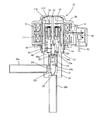
図1は、本発明の一実施例による遊星歯車式減速装置が適用された遊星歯車式電動弁の全体構造を示す縦断面図である。
図1に示す遊星歯車式電動弁(以下、「電動弁」と称する)10は、内部に弁室21を含む弁本体20と、弁本体20の上端に固着されたキャン30と、キャン30の内部で上記弁本体20の上端に取り付けられる弁体駆動機構40と、キャン30の内部で上記弁体駆動機構40に結合された遊星歯車式減速装置100と、キャン30の外側を取り囲む態様で配置されたモータ励磁装置(ステータ装置)50と、を備える。
FIG. 1 is a longitudinal sectional view showing the entire structure of a planetary gear type motor-operated valve to which a planetary gear type reduction gear according to an embodiment of the present invention is applied.
A planetary gear type motor-operated valve (hereinafter referred to as “motor valve”) 10 shown in FIG. 1 includes a valve
弁本体20は、有底筒状の形状を有する例えば金属製の部材であって、上部の開口端に後述する弁体駆動機構40の筒状軸受41を固着することにより、内部に弁室21が形成される。
弁本体20の側部には、弁室21に連通する流入パイプ26aが取り付けられており、弁本体20の底部には、弁室21に連通する小孔(オリフィス)22が形成されるとともに、流出パイプ26bが取り付けられる。
The
An
弁室21の内部には、オリフィス22を開閉する弁体23と、当該弁体23を上方(弁体23の開方向)に付勢するバネ25と、このバネ25の周囲に設けられたバネ受け部材24と、が配置されている。
弁体23は、上端に外向きに拡径するフランジ部23aが形成されており、下端にオリフィス22に挿入されるテーパ部23bが形成されている。
Inside the
The
バネ受け部材24は、弁体23の外側に配置される筒状の部材であって、上端に外向きに拡径するフランジ部24aが形成されており、中間領域に段部24bが形成され、下端近傍は小径とされ、弁体23の外周面に摺動自在に接している。
バネ受け部材24の段部24bと弁体23のフランジ部23aの下面との間には、バネ25が配置される。このような配置により、バネ25が弁体23のフランジ部23aを常時上方に付勢する。
The
A
キャン30は、有頂円筒形の薄肉部材であって、弁本体20の外周面に固着された受け部材31を介して、弁本体20の頂部を収容する態様で取り付けられる。
また、キャン30の内部空間の上方には、後述する遊星歯車式減速装置100の回転軸となるシャフト33を保持するシャフト保持部材32が固着されている。
そして、キャン30は、弁本体20の上部との間に形成される内部空間を密閉する気密容器として機能し、内部空間には、後述する弁体駆動機構40と遊星歯車式減速装置100とを収容する。
The
In addition, a
The can 30 functions as an airtight container that seals an internal space formed between the upper portion of the
弁体駆動機構40は、遊星歯車式減速装置100の出力軸(図2の符号131参照)を収容する収容穴41aを有する筒状軸受41と、上記収容穴41aに収容されるとともに上記出力軸と係合されたねじ軸42と、当該ねじ軸42の一端が接触するボール43と、弁体23の頂部に取り付けられて上記ボール43を支持するボール支持部材44と、から構成される。
筒状軸受41は、弁本体20の頂部の開口に嵌合するように挿入され、上述のバネ受け部材24のフランジ部24aを挟む態様で、弁本体20の内部の段差部20aに接触して固着される。
また、筒状軸受41の収容穴41aの下端には雌ねじが形成されている。
The valve
The
A female screw is formed at the lower end of the accommodation hole 41 a of the
ねじ軸42には、上記雌ねじと螺合する雄ねじがその外周に形成されており、その上端には、遊星歯車式減速装置100の出力軸131に形成されたスリットに挿入される平凸部42aが形成されている。
このような弁体駆動機構40により、遊星歯車式減速装置100の出力軸131が回転すると、当該出力軸131に連結されたねじ軸42も連れ回りし、これによりねじ軸42の回転運動が軸方向の進退運動に変換される。
そして、ねじ軸42の進退運動はボール43及びボール支持部材44を介して弁体23に伝達され、弁体23が軸方向に進退移動する。
The
When the
The forward / backward movement of the
モータ励磁装置50は、ボビンに導線が巻回されたステータコイル51と、当該ステータコイル51に電力を供給するコネクタ52及びリード線53と、を一体に樹脂モールドしたものであって、上記ステータコイル51がキャン30の外周部を囲むような配置で、取付具54を介してキャン30に着脱自在に取り付けられる。
一方、遊星歯車式減速装置100は、キャン30の内部空間に取り付けられたシャフト33が挿入固定されるロータ組立体110を含んでおり、電動弁10において、モータ励磁装置50のステータコイル51と遊星歯車式減速装置100のロータ組立体110とは、電動モータの一例としてのステッピングモータを構成する。
The
On the other hand, the planetary gear
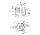
図2は、図1に示された遊星歯車式減速装置の概略を示す図であって、図2(a)は部分断面図であり、図2(b)は図2(a)のB−B断面図である。
図2に示すように、遊星歯車式減速装置100は、有頂円筒状のロータ組立体110(図1参照)と、弁本体20に支持部材121を介して取付固定された環状の内歯車である固定ギア120と、シャフト33に回転自在に支持された出力軸131を有する内歯車である有底円筒状の出力ギア130と、シャフト33を着脱自在に挿入しつつ上記固定ギア120及び出力ギア130の内側に配置されたキャリア140と、キャリア140に回転自在に支持された複数の遊星ギア150と、を備えている。
2A and 2B are diagrams schematically illustrating the planetary gear type speed reducer illustrated in FIG. 1, in which FIG. 2A is a partial cross-sectional view, and FIG. 2B is a cross-sectional view taken along line B- in FIG. It is B sectional drawing.
As shown in FIG. 2, the planetary gear
図1に示されたロータ組立体110は、例えば磁性材料を含有するプラスチック等の樹脂材料で形成され、周壁をなす筒部111と、中央に太陽ギア112aが突設された底部112と、が一体に形成された部材である。
太陽ギア112aは、中心にシャフト33が挿通される貫通孔を有するとともに、外周面には、遊星ギア150と噛合する外歯が形成されている。
なお、筒部111と底部112とは、別々に製造して組み立てても良いし、一体成形によって形成されてもよい。
The
The
In addition, the
固定ギア120は、例えばプラスチック等の樹脂材料を成型加工して製作されたリングギアであって、内周側に遊星ギア150の上側部分と噛合する内歯が形成されている。
また、固定ギア120は、円筒状の支持部材121を介して、弁本体20の上端部に固定される。
The fixed
The fixed
出力ギア130は、例えばプラスチック等の樹脂材料を成型加工して製作された有底円筒状のリングギアであって、その中央に形成された貫通孔に出力軸131が圧入固着されている。
出力ギア130の内壁面には、遊星ギア150と噛合する内歯が形成されている。
The
Inner teeth that mesh with the
出力軸131は、上端側にシャフト33を挿入する挿入穴を有するとともに、下端側には、上述したねじ軸42の平凸部42aが挿入されるスリットが形成されている(図1参照)。
これらの構成により、出力ギア130に固着された出力軸131の回転は、スリットと平凸部との結合(係合)を介してねじ軸42に伝達され、出力ギア130とねじ軸42とが同方向に回転する。
The
With these configurations, the rotation of the
キャリア140は、例えばプラスチック等の樹脂材料を成型加工して製作された樹脂部品、あるいは金属部品であって、シャフト33が挿入される貫通孔を中心部に有する底板部141と、当該底板部141から上方に向けて立設されている3個の隔壁142及び3本の支軸143と、隔壁142及び支軸143の上端(すなわち底板部141と対向する位置)に取り付けられる環状プレート144と、から構成されている。
3個の隔壁142と3本の支軸143とは、隔壁同士あるいは支軸同士が互いに周方向で等間隔となるように交互に配置される。
The
The three
遊星ギア150は、例えばプラスチック等の樹脂材料や金属材料により、上記キャリア140の支軸143が挿入される穴を備えた筒状に形成され、その外周面には、上記した太陽ギア112a、固定ギア120のリングギア及び出力ギア130のリングギアとそれぞれ噛合する外歯が形成されている。
3つの遊星ギア150は、キャリア140の3本の支軸143にそれぞれ回転自在に挿入され、この状態で上方から環状プレート144を取り付けることにより、キャリア140に支持された遊星ギア150が、固定ギア120及び出力ギア130の内側に取り付けられる。
そして、キャリア140、遊星ギア150及び環状プレート144は、遊星ギア組立体を構成している。
The
The three
The
補助ギア160は、例えばプラスチック等の樹脂材料により筒状に形成されている。この補助ギア160の内周面は、太陽ギア112aを固定又は回転自在に支持するシャフト33が挿入される穴とされており、その外周面には、上記した3つの遊星ギア150とそれぞれ噛合する外歯が形成されている。
また、補助ギア160は、太陽ギア112aと同一の歯数で形成されているが、当該補助ギア160と遊星ギア150とが噛み合うときのバックラッシュ(両ギア間の隙間)が、太陽ギア112aと遊星ギア150とが噛み合うときのバックラッシュよりも小さくなるように、補助ギア160の転位量は太陽ギア112aの転位量と異なるように設定される。
The
The
太陽ギア112aの歯幅(ギアに形成された歯のギア回転軸方向の長さ)と固定ギア120の歯幅とは、図2に示すようにほぼ同一(すなわち、太陽ギア112aの下端位置と固定ギア120の下端位置とが同一面上に位置する状態)となるように設定される。
さらに、太陽ギア112aと固定ギア120とは、遊星ギア150を挟んで正対する位置となる。
The tooth width of the
Further, the
また、補助ギア160は、遊星ギア150を挟んで出力ギア130と正対する位置となっている。このとき、上述のように、補助ギア160と遊星ギア150とが噛み合うときのバックラッシュが、太陽ギア112aと遊星ギア150とが噛み合うときのバックラッシュよりも小さくなるように転位量が設定されているため、従来の遊星歯車式減速装置において懸念されていた遊星ギアの傾斜(遊星ギアがキャリアの支軸に対して当該遊星ギアの公転方向に傾斜する事象)が緩和される。
これにより、遊星ギア150の上端側では太陽ギア112aとの噛み合いが確保され、下端側では補助ギア160との噛み合いが確保されるため、遊星ギア150が支軸143に対して傾斜あるいはガタつくことなく、出力ギア130との間における回転の伝達も安定する。
Further, the
As a result, the
固定ギア120と出力ギア130とは、互いに転位した関係にあり、互いの歯数がわずかに異なるように構成されている。
一方、遊星ギア150を支持するキャリア140は、シャフト33を中心に自由に回転できる配置とされている。
このため、遊星ギア150が固定ギア120及び出力ギア130と噛み合った状態で自転及び公転すると、固定ギア120に対して出力ギア130が回転することとなる。
The fixed
On the other hand, the
For this reason, when the
したがって、遊星歯車式減速装置100は、ロータ組立体110の回転、すなわち太陽ギア112aから入力される回転が、遊星ギア150を介して、大きく減速されて出力ギア130の出力軸131から出力される。
そして、上述のとおり、出力軸131の回転は、弁体駆動機構40のねじ軸42を介して、弁体23が微細な進退運動可能となるように変換される。
これらの構造により、本発明による遊星歯車式減速装置100は、シャフト33に関して太陽ギア112aと同軸に回転する補助ギア160を、太陽ギア112aとキャリア140の底板部141との間に設けたため、遊星ギア150と太陽ギア112aとの噛み合い長さを短くすることができるため、太陽ギア112aと遊星ギア150との間での回転の伝達効率を向上させることができる。
Therefore, in the planetary gear
Then, as described above, the rotation of the
With these structures, the planetary gear
なお、本発明は上記の実施例に限定されるものではなく、種々の改変を施すことができる。
すなわち、上記した実施例では、補助ギア160の転位量を太陽ギア112aの転位量と異なる値に設定することにより、補助ギア160と遊星ギア150とが噛み合うときのバックラッシュが、太陽ギア112aと遊星ギア150とが噛み合うときのバックラッシュよりも小さくなる場合を例示したが、単に歯厚を変えることにより、バックラッシュを調整するように構成しても良いことは当然である。
The present invention is not limited to the above-described embodiments, and various modifications can be made.
That is, in the above-described embodiment, by setting the shift amount of the
10 遊星歯車式電動弁
20 弁本体
21 弁室
22 オリフィス
23 弁体
24 バネ受け部材
25 バネ
30 キャン
31 受け部材
32 シャフト保持部材
33 シャフト
40 弁体駆動機構
41 筒状軸受
42 ねじ軸
43 ボール
44 ボール支持部材
50 モータ励磁装置
51 ステータコイル
52 コネクタ
53 リード線
54 取付具
100 遊星歯車式減速装置
110 ロータ組立体
111 筒部
112 底部
112a 太陽ギア
120 固定ギア
121 支持部材
130 出力ギア
131 出力軸
140 キャリア
141 底板部
142 隔壁
143 支軸
144 環状プレート
150 遊星ギア
160 補助ギア
DESCRIPTION OF
Claims (6)
前記太陽ギアと同心状に固定される固定ギアと、
前記太陽ギア及び前記固定ギアの双方と同時に噛み合う遊星ギアと、
前記シャフトの中心軸を中心に回転する底板部及び前記遊星ギアを回転自在に支持する支軸からなるキャリアと、
前記遊星ギアに噛み合う出力ギアと、
を含む遊星歯車式減速装置であって、
前記太陽ギアと前記キャリアの前記底板部との間に、前記太陽ギアと同心状に回転して前記遊星ギアと噛み合う補助ギアをさらに備える
ことを特徴とする遊星歯車式減速装置。 A sun gear supported by a shaft;
A fixed gear fixed concentrically with the sun gear;
A planetary gear meshing simultaneously with both the sun gear and the fixed gear;
A carrier comprising a bottom plate portion that rotates about the central axis of the shaft and a support shaft that rotatably supports the planetary gear;
An output gear meshing with the planetary gear;
A planetary gear speed reducer including
A planetary gear type reduction device further comprising an auxiliary gear that rotates concentrically with the sun gear and meshes with the planetary gear between the sun gear and the bottom plate portion of the carrier.
請求項1に記載の遊星歯車式減速装置。 The sun gear and the fixed gear have tooth widths such that the meshing widths with the planetary gears are substantially the same, respectively.
The planetary gear type reduction gear according to claim 1.
請求項1又は2に記載の遊星歯車式減速装置。 The auxiliary gear is different in gear shape from the sun gear,
The planetary gear type reduction gear according to claim 1 or 2.
請求項3に記載の遊星歯車式減速装置。 The auxiliary gear is formed in such a shape that a backlash when the auxiliary gear and the planetary gear mesh with each other is smaller than a backlash when the sun gear and the planetary gear mesh with each other.
The planetary gear type reduction gear according to claim 3.
請求項1〜4のいずれか1項に記載の遊星歯車式減速装置。 The auxiliary gear is formed of a resin material,
The planetary gear type reduction gear device according to any one of claims 1 to 4.
Priority Applications (1)
| Application Number | Priority Date | Filing Date | Title |
|---|---|---|---|
| JP2016088200A JP6709674B2 (en) | 2016-04-26 | 2016-04-26 | Planetary gear type speed reducer and motor-operated valve equipped with the same |
Applications Claiming Priority (1)
| Application Number | Priority Date | Filing Date | Title |
|---|---|---|---|
| JP2016088200A JP6709674B2 (en) | 2016-04-26 | 2016-04-26 | Planetary gear type speed reducer and motor-operated valve equipped with the same |
Publications (2)
| Publication Number | Publication Date |
|---|---|
| JP2017198260A true JP2017198260A (en) | 2017-11-02 |
| JP6709674B2 JP6709674B2 (en) | 2020-06-17 |
Family
ID=60239134
Family Applications (1)
| Application Number | Title | Priority Date | Filing Date |
|---|---|---|---|
| JP2016088200A Active JP6709674B2 (en) | 2016-04-26 | 2016-04-26 | Planetary gear type speed reducer and motor-operated valve equipped with the same |
Country Status (1)
| Country | Link |
|---|---|
| JP (1) | JP6709674B2 (en) |
Cited By (4)
| Publication number | Priority date | Publication date | Assignee | Title |
|---|---|---|---|---|
| JP2023047864A (en) * | 2021-09-27 | 2023-04-06 | 株式会社不二工機 | electric valve |
| JP2023544654A (en) * | 2020-12-29 | 2023-10-24 | 浙江三花商用制冷有限公司 | electric valve |
| JP2024104254A (en) * | 2023-01-23 | 2024-08-02 | 株式会社不二工機 | Motor-operated valve |
| JP2024104253A (en) * | 2023-01-23 | 2024-08-02 | 株式会社不二工機 | Motor-operated valve |
Citations (2)
| Publication number | Priority date | Publication date | Assignee | Title |
|---|---|---|---|---|
| JP2009287674A (en) * | 2008-05-29 | 2009-12-10 | Fuji Koki Corp | Gear support device for planetary gear type reduction gear, and canned planetary gear type motor operated valve with the same |
| JP2012067835A (en) * | 2010-09-22 | 2012-04-05 | Fuji Koki Corp | Planetary gear mechanism and motor-operated valve using the same |
-
2016
- 2016-04-26 JP JP2016088200A patent/JP6709674B2/en active Active
Patent Citations (3)
| Publication number | Priority date | Publication date | Assignee | Title |
|---|---|---|---|---|
| JP2009287674A (en) * | 2008-05-29 | 2009-12-10 | Fuji Koki Corp | Gear support device for planetary gear type reduction gear, and canned planetary gear type motor operated valve with the same |
| JP5111240B2 (en) * | 2008-05-29 | 2013-01-09 | 株式会社不二工機 | Gear support device in planetary gear type reduction gear |
| JP2012067835A (en) * | 2010-09-22 | 2012-04-05 | Fuji Koki Corp | Planetary gear mechanism and motor-operated valve using the same |
Cited By (9)
| Publication number | Priority date | Publication date | Assignee | Title |
|---|---|---|---|---|
| JP2023544654A (en) * | 2020-12-29 | 2023-10-24 | 浙江三花商用制冷有限公司 | electric valve |
| JP7535666B2 (en) | 2020-12-29 | 2024-08-16 | 浙江三花商用制冷有限公司 | Motor-operated valve |
| US12480597B2 (en) | 2020-12-29 | 2025-11-25 | Zhejiang Sanhua Commercial Refrigeration Controls Co., Ltd | Electric valve |
| JP2023047864A (en) * | 2021-09-27 | 2023-04-06 | 株式会社不二工機 | electric valve |
| JP7341523B2 (en) | 2021-09-27 | 2023-09-11 | 株式会社不二工機 | electric valve |
| JP2024104254A (en) * | 2023-01-23 | 2024-08-02 | 株式会社不二工機 | Motor-operated valve |
| JP2024104253A (en) * | 2023-01-23 | 2024-08-02 | 株式会社不二工機 | Motor-operated valve |
| JP7770692B2 (en) | 2023-01-23 | 2025-11-17 | 株式会社不二工機 | Motor-operated valve |
| JP7778378B2 (en) | 2023-01-23 | 2025-12-02 | 株式会社不二工機 | Electric valve |
Also Published As
| Publication number | Publication date |
|---|---|
| JP6709674B2 (en) | 2020-06-17 |
Similar Documents
| Publication | Publication Date | Title |
|---|---|---|
| JP5647844B2 (en) | Motorized valve | |
| CN101067462B (en) | Electric valve | |
| KR101099069B1 (en) | Reduction gear attached motor-operated valve | |
| KR101090998B1 (en) | A reducer having a motor | |
| JP5550043B2 (en) | Electromagnetic clutch | |
| JP6709674B2 (en) | Planetary gear type speed reducer and motor-operated valve equipped with the same | |
| US20160195169A1 (en) | Reducer | |
| JP6606328B2 (en) | Reduction mechanism and drive unit with reduction gear | |
| JP5022960B2 (en) | Electric valve with reduction gear unit | |
| JP6420097B2 (en) | Face gear reducer | |
| KR20180090755A (en) | Actuator | |
| JP2008014485A (en) | Motor driven valve | |
| JP2008045740A (en) | Geared motor | |
| JP2017198259A (en) | Planetary gear type reduction gear and motor-driven valve including the same | |
| JP2016211706A (en) | Speed reducer and robot | |
| JP2016001002A (en) | Electric motor drive device and planetary gear unit | |
| JP2013155800A (en) | Gear device | |
| KR102285830B1 (en) | Actuator having cycloide reducer for coolant valve | |
| JP2007211905A (en) | Reduction gear | |
| JP2015113922A (en) | Reduction gear | |
| JP2006304558A (en) | Hypocycloid reducer with built-in motor | |
| JP2008240746A (en) | Motor with speed reducer | |
| JP6602674B2 (en) | Planetary gear mechanism | |
| JP5456801B2 (en) | Geared motor | |
| JP2006300273A (en) | Hypocycloid reducer with built-in motor |
Legal Events
| Date | Code | Title | Description |
|---|---|---|---|
| A621 | Written request for application examination |
Free format text: JAPANESE INTERMEDIATE CODE: A621 Effective date: 20190314 |
|
| A977 | Report on retrieval |
Free format text: JAPANESE INTERMEDIATE CODE: A971007 Effective date: 20200123 |
|
| A131 | Notification of reasons for refusal |
Free format text: JAPANESE INTERMEDIATE CODE: A131 Effective date: 20200128 |
|
| A521 | Request for written amendment filed |
Free format text: JAPANESE INTERMEDIATE CODE: A523 Effective date: 20200325 |
|
| TRDD | Decision of grant or rejection written | ||
| A01 | Written decision to grant a patent or to grant a registration (utility model) |
Free format text: JAPANESE INTERMEDIATE CODE: A01 Effective date: 20200428 |
|
| A61 | First payment of annual fees (during grant procedure) |
Free format text: JAPANESE INTERMEDIATE CODE: A61 Effective date: 20200525 |
|
| R150 | Certificate of patent or registration of utility model |
Ref document number: 6709674 Country of ref document: JP Free format text: JAPANESE INTERMEDIATE CODE: R150 |
|
| R250 | Receipt of annual fees |
Free format text: JAPANESE INTERMEDIATE CODE: R250 |
|
| R250 | Receipt of annual fees |
Free format text: JAPANESE INTERMEDIATE CODE: R250 |