JP2017199459A - Induction heating cooker - Google Patents
Induction heating cooker Download PDFInfo
- Publication number
- JP2017199459A JP2017199459A JP2016086777A JP2016086777A JP2017199459A JP 2017199459 A JP2017199459 A JP 2017199459A JP 2016086777 A JP2016086777 A JP 2016086777A JP 2016086777 A JP2016086777 A JP 2016086777A JP 2017199459 A JP2017199459 A JP 2017199459A
- Authority
- JP
- Japan
- Prior art keywords
- inverter board
- main body
- cooling air
- heat
- disposed
- Prior art date
- Legal status (The legal status is an assumption and is not a legal conclusion. Google has not performed a legal analysis and makes no representation as to the accuracy of the status listed.)
- Granted
Links
Images


Landscapes
- Induction Heating Cooking Devices (AREA)
Abstract
【課題】限られた本体スペースを有効活用してファンの送風方向や基板のレイアウト・大きさに制約を低減し、冷却性能を確保することができること。【解決手段】第1の冷却風の流れ29と第2の冷却風の流れ33を風の流れの方向が互いに異なる向きであり、且つ、風の流れが互いに異なる高さのねじれの位置とすることで、相互の熱影響を低減するとともに、インバータ基板の放熱部の長手大きさにあわせて、本体長手方向にレイアウトすることでレイアウトの制約低減を行い、冷却性能を確保することができる。【選択図】図1PROBLEM TO BE SOLVED: To effectively utilize a limited main body space, reduce restrictions on a fan blowing direction and a layout / size of a substrate, and secure cooling performance. SOLUTION: A first cooling air flow 29 and a second cooling air flow 33 are twisted positions in which the directions of the wind flows are different from each other and the wind flows are at different heights. As a result, mutual thermal influences can be reduced, and layout restrictions can be reduced by laying out in the longitudinal direction of the main body according to the longitudinal size of the heat radiating portion of the inverter substrate, and cooling performance can be ensured. [Selection diagram] Fig. 1
Description
本発明は、トッププレート上に載置された金属製の調理用鍋などの被加熱物を誘導加熱する誘導加熱調理器に関するものである。 The present invention relates to an induction heating cooker that induction-heats an object to be heated such as a metal cooking pan placed on a top plate.
従来、この種の誘導加熱調理器の構成としては、複数の加熱インバータ基板の放熱部に流れる冷却風の向きは略同一方向とし、相互の熱影響を低減しているものがある(例えば、特許文献1参照)。 Conventionally, as a configuration of this type of induction heating cooker, there is a configuration in which the direction of the cooling air flowing through the heat radiating portions of the plurality of heating inverter boards is set to be substantially the same direction to reduce mutual heat influence (for example, patents) Reference 1).
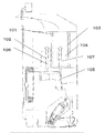
図8は、前記特許文献1に記載された従来の誘導加熱調理器の上下に配置されたインバータ基板と冷却風路を示す断面図である。
FIG. 8 is a cross-sectional view showing inverter boards and cooling air passages arranged above and below the conventional induction heating cooker described in
図8に示すように、上下の高さの違う位置にインバータ基板を配した構成で、上方に配された第1のインバータ基板101とインバータ基板に配置されており、第1のインバータ基板のスイッチング素子の熱を放熱する第1の放熱部102と、下方に配された第2のインバータ基板103とインバータ基板に配置されており、第2のインバータ基板のスイッチング素子の熱を放熱する第2の放熱部104と、前記本体内に配置されており、第1の放熱部102及び第2の放熱部104を冷却する冷却風を発生させる送風部105を備え、前記本体内には、第1の放熱部102を冷却する第1の冷却風路106と、第2の放熱部104を冷却する第2の冷却風路107とが形成されており、第1の冷却風路106と第2の冷却風路107とは、同じ向きとしている。
As shown in FIG. 8, the inverter board is arranged at different positions in the vertical direction, and is arranged on the inverter board with the
しかしながら、前記従来の構成では、互いの冷却風の熱影響がないよう配慮して上下の高さの違う位置にインバータ基板を配置し、第1の冷却風路と前記第2の冷却風路とは、同じ向きとしている。また、同じ高さの異なる向きの複数の冷却風路が存する場合には互いの冷却風の熱を受け冷却性能が低下するため、複数の冷却風路を同じ向きに並列に並べて構成して互いの冷却風の熱影響がないよう配慮して冷却性能を確保する必要があるという課題を有していた。 However, in the conventional configuration, the inverter board is disposed at a position where the vertical height is different so that there is no thermal influence of the cooling air, and the first cooling air passage and the second cooling air passage are arranged. Have the same orientation. In addition, when there are multiple cooling air passages with the same height and different orientations, the cooling performance is reduced due to the heat of each cooling air, so the multiple cooling air passages are arranged side by side in parallel in the same direction. There was a problem that it was necessary to ensure the cooling performance in consideration of not having the heat effect of the cooling air.
本発明は前記従来の課題を解決するもので、限られた本体スペースを有効活用して冷却性能を確保することができる誘導加熱調理器を提供することを目的としている。 This invention solves the said conventional subject, and it aims at providing the induction heating cooking appliance which can ensure cooling performance by utilizing effectively the limited main body space.
前記従来の課題を解決するために、本発明の誘導加熱調理器は、被加熱物が載置されるトッププレートを有する本体と、本体内に配置されており、前記トッププレートに載置された被加熱物を誘導加熱する第1の加熱コイルと、前記本体内に配置されており、前記トッププレートに載置された被加熱物を誘導加熱する第2の加熱コイルと、前記本体内に配置されており、前記第1の加熱コイルに高周波電流を供給する第1のインバータ基板と、前記本体内に配置されており、前記第2の加熱コイルに高周波電流を供給する第2のインバータ基板と、前記第1のインバータ基板に配置されており、前記第1のインバータ基板の発熱部品の熱を放熱する第1の放熱部と、前記第2のインバータ基板に配置されており
、前記第2のインバータ基板の発熱部品の熱を放熱する第2の放熱部と、前記本体内に配置されており、前記第1の放熱部を冷却する冷却風を発生させる第1の送風部と、前記本体内に配置されており、前記第2の放熱部を冷却する冷却風を発生させる第2の送風部と、を備え、前記第1の送風部で発生された冷却風が前記第1の放熱部を冷却する流れと前記第2の送風部で発生された冷却風が前記第2の放熱部を冷却する流れとが、ねじれの位置にある、としたものである。
In order to solve the above-described conventional problems, an induction heating cooker according to the present invention has a main body having a top plate on which an object to be heated is placed, and is disposed in the main body, and is placed on the top plate. A first heating coil that induction-heats the object to be heated and a second heating coil that is arranged in the main body and induction-heats the object to be heated placed on the top plate, and is arranged in the main body A first inverter board that supplies a high-frequency current to the first heating coil; and a second inverter board that is disposed in the main body and supplies the high-frequency current to the second heating coil; , Disposed on the first inverter board, disposed on the second inverter board, and a first heat radiating portion for radiating heat of the heat-generating component of the first inverter board, and the second inverter board. Inverter board A second heat dissipating part that dissipates the heat of the thermal component, and a first air blowing part that generates cooling air that cools the first heat dissipating part, and is disposed in the main body. And a second air blowing section that generates cooling air that cools the second heat radiating section, and the cooling air generated by the first air blowing section cools the first heat radiating section. And the flow in which the cooling air generated by the second air blowing unit cools the second heat radiating unit is in a twisted position.
これによって、第1の冷却風の流れと第2の冷却風のながれが異なる向き・異なる高さのねじれの位置とすることで、相互の熱影響を低減するとともに、インバータ基板の放熱部の長手大きさにあわせて、本体長手方向にレイアウトすることでレイアウトの制約低減を行い、冷却性能を確保することができる。 Thereby, the flow of the first cooling air and the flow of the second cooling air have different directions and positions of torsion of different heights, thereby reducing the mutual thermal effect and the length of the heat dissipation part of the inverter board. By laying out in the longitudinal direction of the main body according to the size, layout constraints can be reduced and cooling performance can be ensured.
本発明の誘導加熱調理器は、限られた本体スペースを有効活用して相互の熱影響を低減するとともに、ファンの送風方向や基板のレイアウト・大きさに制約の低減を行い、冷却性能を確保することができる。 The induction heating cooker of the present invention makes effective use of the limited main body space to reduce the mutual thermal effect, and also reduces the restrictions on the fan blowing direction and board layout / size to ensure cooling performance can do.
第1の発明は、被加熱物が載置されるトッププレートを有する本体と、本体内に配置されており、前記トッププレートに載置された被加熱物を誘導加熱する第1の加熱コイルと、前記本体内に配置されており、前記トッププレートに載置された被加熱物を誘導加熱する第2の加熱コイルと、前記本体内に配置されており、前記第1の加熱コイルに高周波電流を供給する第1のインバータ基板と、前記本体内に配置されており、前記第2の加熱コイルに高周波電流を供給する第2のインバータ基板と、前記第1のインバータ基板に配置されており、前記第1のインバータ基板の発熱部品の熱を放熱する第1の放熱部と、前記第2のインバータ基板に配置されており、前記第2のインバータ基板の発熱部品の熱を放熱する第2の放熱部と、前記本体内に配置されており、前記第1の放熱部を冷却する冷却風を発生させる送風部と、前記本体内に配置されており、前記第2の放熱部を冷却する冷却風を発生させる第2の送風部と、を備え、前記第1の送風部で発生された冷却風が前記第1の放熱部を冷却する流れと前記第2の送風部で発生された冷却風が前記第2の放熱部を冷却する流れとが、ねじれの位置にある構成とすることにより、通常同じ高さの異なる向きの複数の冷却風路が存する場合には互いの冷却風の熱を受け冷却性能が低下するため
、複数の冷却風路を同じ向きに並列に並べて構成して互いの冷却風の熱影響がないよう配慮して冷却性能を確保する必要があり、冷却風の流れのレイアウト方向に制約をうけ、しいては放熱部・ファン・基板のレイアウトが制約をうけることとなり、放熱部やファン・基板の向きを前後左右自由にレイアウトすることができず、限られた本体スペースを有効活用することができなかったが、第1の冷却風の流れと第2の冷却風の流れが異なる向き・異なる高さのねじれの位置で相互の熱影響を少なくすることとなり、互いのインバータの冷却風の影響を考慮することなく、インバータ基板の放熱部の長手大きさにあわせて、本体長手方向にレイアウトし、冷却性能を考慮したレイアウトの制約をなくすことができ、限られた本体スペースを有効活用して、複数インバータからの相互の熱影響を低減するとともに、ファンの送風方向や基板の放熱部のレイアウト・大きさに制約を受けることなく、冷却性能を向上するとともに、コンパクトに本体を構成でき省スペース化を図ることができる。
A first invention includes a main body having a top plate on which an object to be heated is placed, a first heating coil disposed in the main body and induction-heating the object to be heated placed on the top plate; A second heating coil disposed in the main body for inductively heating an object to be heated placed on the top plate, and a high-frequency current disposed in the main body, A first inverter board for supplying high-frequency current to the second heating coil, and a first inverter board for supplying high-frequency current to the second heating coil, A first heat dissipating part for dissipating heat of the heat generating component of the first inverter board; and a second heat dissipating member for dissipating heat of the heat generating component of the second inverter board. Heat sink and the book A blower that generates cooling air that cools the first heat dissipating part and a second that generates cooling air that cools the second heat dissipating part. The cooling air generated by the first air blowing unit cools the first heat radiating unit, and the cooling air generated by the second air blowing unit generates the second heat dissipation. When the plurality of cooling air passages having the same height and different orientations usually exist, the cooling performance is deteriorated due to the heat of each other cooling air. Therefore, it is necessary to arrange multiple cooling air paths in parallel in the same direction to ensure that the cooling performance is ensured so that there is no thermal effect from each other, and there is a restriction on the layout direction of the cooling air flow. However, the layout of the heat sink, fan, and board may be restricted. However, the direction of the heat radiation part and the fan / board could not be laid out freely in front, back, left, and right, and the limited body space could not be used effectively, but the flow of the first cooling air and the second cooling Mutual thermal effects are reduced at different twist directions and at different heights of the wind flow, and the length of the heat dissipation part of the inverter board is adjusted without considering the effects of the inverter cooling air. Layout in the longitudinal direction of the main body, eliminating the restrictions on the layout considering the cooling performance, effectively utilizing the limited main body space, reducing the mutual thermal influence from multiple inverters, and blowing the fan It is possible to improve the cooling performance without being restricted by the direction and layout / size of the heat dissipation part of the board and to make the main body compact and save space. it can.
第2の発明は、特に第1の発明において、前記第1の送風部は、前記第1の送風部で発生された冷却風を前記第1の送風部の外部に送風する第1の送風口を有しており、前記第2の送風部は、前記第2の送風部で発生された冷却風を前記第2の送風部の外部に送風する第2の送風口を有しており、前記第1の送風口と前記第2の送風口とは、前記本体の高さ方向において異なる高さに位置していることにより、第1の送風口からの冷却風路と第2の送風口からの冷却風路が異なる高さ位置で相互の風流れの影響と熱影響を低減することとなり、冷却性能を向上することができる。 According to a second aspect of the invention, particularly in the first aspect of the invention, the first blower portion sends a cooling air generated by the first blower portion to the outside of the first blower portion. The second air blowing unit has a second air blowing port for blowing the cooling air generated by the second air blowing unit to the outside of the second air blowing unit, and The first air outlet and the second air outlet are located at different heights in the height direction of the main body, so that the cooling air passage from the first air outlet and the second air outlet Thus, the cooling air flow path and the heat effect are reduced at different height positions, and the cooling performance can be improved.
第3の発明は、特に、第2の発明において、前記第1のインバータ基板及び前記第2のインバータ基板は、前記第1のインバータ基板に配置された発熱部品の数が前記第2のインバータ基板に配置された発熱部品の数以上となるように構成されており、前記第1のインバータ基板は、前記本体の高さ方向において、前記第2のインバータ基板よりも上方に位置しており、前記第2の送風口は、前記本体の高さ方向において、前記第1の送風口よりも下方に位置している、ことにより、多くの熱量を放熱しなければならない第1の放熱部と第1の送風口が上方になるようになり、温度が高い冷却風路を上方、比較して温度が低い冷却風路を下方に形成され、熱い空気が上へ向かう上昇気流による影響を低減することにより、相互の風流れの影響と熱影響をより低減することとなり、冷却性能を向上することができる。 According to a third aspect of the invention, in particular, in the second aspect of the invention, the first inverter board and the second inverter board have the same number of heat-generating components arranged on the first inverter board as the second inverter board. The first inverter board is located above the second inverter board in the height direction of the main body, The second air outlet is positioned below the first air outlet in the height direction of the main body, so that the first heat dissipating part and the first heat must dissipate a large amount of heat. The cooling air passage is formed at the top, the cooling air passage with a high temperature is formed upward, and the cooling air passage with a low temperature is formed below, and the influence of the rising air flowing upward is reduced. The effect of mutual wind flow It becomes possible to further reduce the thermal effects, thereby improving the cooling performance.
第4の発明は、特に第1〜3の発明において、前記第1のインバータ基板及び前記第2のインバータ基板は、一辺が長辺となる長方形状であり、前記第1の送風部で発生された冷却風は、前記第1のインバータ基板の長手方向に沿って前記第1の放熱部を冷却しており、前記第2の送風部で発生された冷却風は、前記第2のインバータ基板の短手方向に沿って前記第2の放熱部を冷却することにより、冷却性能を考慮することなく、インバータ基板の長手大きさにあわせて、本体長手方向にレイアウトし、また、インバータ基板の短手大きさにあわせて、本体短手方向にレイアウトし、冷却性能を考慮したレイアウトの制約をなくすことができ、限られた本体スペースを有効活用して、複数インバータからの相互の熱影響を低減するとともに、ファンの送風方向や基板のレイアウト・大きさに制約を受けることなく、冷却性能を向上するとともに、コンパクトに本体を構成でき省スペース化を図ることができる。 In a fourth aspect of the invention, particularly in the first to third aspects of the invention, the first inverter board and the second inverter board have a rectangular shape with one side being a long side, and are generated by the first blower. The cooling air cools the first heat radiating part along the longitudinal direction of the first inverter board, and the cooling air generated by the second air blowing part is generated by the second inverter board. By cooling the second heat dissipating part along the short direction, it is laid out in the longitudinal direction of the main body in accordance with the longitudinal size of the inverter board without considering the cooling performance. According to the size, it can be laid out in the short direction of the main unit, eliminating the restrictions on the layout considering the cooling performance, and making effective use of the limited main unit space to reduce the mutual thermal effects from multiple inverters. With Without being limited to the blowing direction and layout size of the substrate of the fan, as well as improve the cooling performance, it can be made compact in construction can save space the body.
第5の発明は、特に第3または第4の発明において、前記第1のインバータ基板の下方には、前記第1のインバータ基板を前記本体内に保持する支持部材が配置されており、前記支持部材は金属で形成されており、前記支持部材の下方には、前記第1のインバータ基板及び前記第2のインバータ基板に電力を供給する電源基板が配置された、とすることにより、他の部品特に第1のインバータ基板及び第2のインバータ基板が発する漏洩磁束を金属で形成された支持部材で電源基板に対して遮蔽し、ノイズ遮蔽性能を向上することが
できる。
According to a fifth aspect of the invention, particularly in the third or fourth aspect of the invention, a support member for holding the first inverter board in the main body is disposed below the first inverter board, and the support The member is made of metal, and a power supply board that supplies power to the first inverter board and the second inverter board is disposed below the support member, so that other components are provided. In particular, the leakage magnetic flux generated by the first inverter board and the second inverter board can be shielded against the power supply board by the support member made of metal, and the noise shielding performance can be improved.
以下、本発明の実施の形態について、図面を参照しながら説明する。なお、この実施の形態によって本発明が限定されるものではない。 Hereinafter, embodiments of the present invention will be described with reference to the drawings. Note that the present invention is not limited to the embodiments.
(実施の形態1)
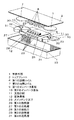
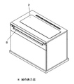
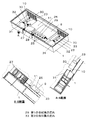
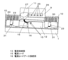
図1は、本発明の実施の形態1における誘導加熱調理器の構成概略図、図2は、本発明の実施の形態1における第1の誘導加熱エリア及び第2の誘導加熱エリアと各エリアの加熱コイルの配置を被加熱物を載置したトッププレートの上面からみた図、図3は、本発明の実施の形態1における誘導加熱調理器をキッチンにセットした状態斜視図、図4は、本発明の実施の形態1における誘導加熱調理器の冷却風路と基板配置を示す斜視図、図5は、本発明の実施の形態1における誘導加熱調理器の電源コード接続を示す概略図、図6は、本発明の実施の形態1における誘導加熱調理器の部分断面構成および回路構成を示すブロック図、図7は、本発明の実施の形態1における整流平滑部およびインバータ回路の回路図である。
(Embodiment 1)
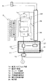
FIG. 1 is a schematic configuration diagram of an induction heating cooker according to
この誘導加熱調理器は、キッチンなどのキャビネットに組み込んで使用される。本発明の実施の形態の誘導加熱調理器は、金属で形成された誘導加熱調理器の本体外郭1と本体外郭1上面に設けられたトッププレート2と、高周波磁界を発生させることによって、トッププレート2上の被加熱物3を誘導加熱する加熱コイルとを備える。トッププレート2は、結晶化ガラスなどの電気絶縁物からなり、トッププレート2の横幅寸法を、奥行き寸法より大とした形状で、被調理物を入れる鍋などの被加熱物3が載置される第1の誘導加熱エリア4及び第2の誘導加熱エリア5を有し、第2の誘導加熱エリア5を第1の誘導加熱エリア4の左右両方に配置している。
This induction heating cooker is used by being incorporated in a cabinet such as a kitchen. The induction heating cooker according to the embodiment of the present invention includes a main body
それぞれ、寸法はトッププレート2の左右幅900mm奥行幅360mm。第1の誘導加熱エリア4は左右幅380mm中心振り分け、奥行幅190mmトッププレート前端面より200mm奥を中心として前後に中心振り分けした長方形形状。第2の誘導加熱エリア5は左右ピッチ600mm中心振り分けとし、奥行方向をトッププレート前端面より200mm奥を中心とした□190mmの正方形形状である。
The dimensions of the
第1の誘導加熱エリア4直下の第1の加熱コイル6は、短径80mm長径180mmの楕円形のコイル4個を、長径を前後方向向きとして横一列に95mm間隔で並べたものである。
The
第2の誘導加熱エリア5直下の第2の加熱コイル7は、直径170mmの円形コイルである。本体外郭は左右幅800mm奥行方向300mm高さ200mmの上方が開口した金属の箱型形状をしている。
The
トッププレート2の使用者側には、図3に示すように、加熱の開始/停止などを使用者が指示するための操作表示部8が設けられている。
On the user side of the
図1に示すように、中央の第1の誘導加熱エリア4直下の第1の加熱コイル6の下方には、第1の加熱コイル6に高周波電流を供給する第1のインバータ基板9を配し、左右の第2の誘導加熱エリア5直下の第2の加熱コイル7の下方には、第2の加熱コイル7に高周波電流を供給する第2のインバータ基板10を配している。第2のインバータ基板10の少なくとも一部が第1のインバータ基板9の下方に位置している。第1のインバータ基板9の下方には、第1のインバータ基板9を本体内に保持する支持部材11が配置されており、支持部材11は金属で形成されており、金属の本体外郭に直接締結されている。
As shown in FIG. 1, a first inverter board 9 for supplying a high-frequency current to the
図5、図6に示すように、支持部材11の下方には、調理器に電力を供給する電源基板12が配置されており、電源基板12には、外部商用電源から電力を取り入れる本体への電源接続部13と外部商用電源に対する電源ノイズフィルタ部14とを備えている。支持部材11の下方の外郭後側面開口穴より挿入された電源コード15の電源コードの電源接続部13をノイズフィルタ部の端子台に端子ねじにより接続している。また、電源コードアース接続部16は、支持部材11の下方で外郭底面に締め付けて接続している。ノイズフィルタ部および電源コード15の電源接続部13および電源コードアース接続部16の上面と左右を囲うよう金属の支持部材11が形成されている。
As shown in FIG. 5 and FIG. 6, a
第2のインバータ基板10は本体外郭1底に、電源基板12と略同高さに配置され、第2のインバータ基板10と電源基板12の間には金属で形成された支持部材11の支持壁が配されている。
The
第1のインバータ基板9および第2のインバータ基板10は商用電源から電源ノイズフィルタ部14を通して供給される交流電圧を直流電圧に変換する整流平滑部17と、整流平滑部から直流電圧を供給されて高周波電流を生成し、生成した高周波電流を加熱コイルに出力するインバータ回路18とが設けられる。また、商用電源と整流平滑部17との間に、商用電源から整流平滑部17に流れる入力電流を検出するための入力電流検知部19が設けられている。図7に示すように、整流平滑部17は、ブリッジダイオードで構成される全波整流器20と、全波整流器の出力端子間に接続された、チョークコイル21及び平滑コンデンサ22で構成されるローパスフィルタと、を有する。インバータ回路は、スイッチング素子23(本実施の形態ではIGBT)と、スイッチング素子23と逆並列に接続されたダイオード24と、加熱コイルに並列に接続された共振コンデンサ25と、を有する。インバータ回路のスイッチング素子23がオン/オフすることによって、高周波電流が発生し、インバータ回路と加熱コイルとで高周波インバータを構成している。このため、スイッチグ素子は発熱が大きく、部品の許容温度を超えないよう発熱部品であるスイッチン素子の熱を放熱し、冷却する必要があり、スイッチング素子23には、スイッチング素子23の熱を放熱するアルミの押し出しで形成された放熱部をスイッチング素子23にねじ締めで取り付けている。
The first inverter board 9 and the
図1、図4に示すように、第1のインバータ基板9は第1の加熱コイル6である4つの楕円コイルに対し高周波電流を流すために4つのスイッチング素子23を有しており、すべてを第1の放熱部26にねじ締めにより取り付けている。そのため、第1の放熱部26は細長い形状をしている。第1のインバータ基板9は、一辺が長辺となる長方形状としており、第1のインバータ基板9の長辺と第1の放熱部26の長手は同一方向に配置され、第1の放熱部26の端部には、第1の放熱部26を冷却する冷却風を発生させる第1の送風部27で発生された冷却風を第1の放熱部26に向かって送風する第1の送風口28を配している。第1のインバータ基板9の長手方向と本体外郭の長手方向は同一方向となるように配置している。第1の送風部27はシロッコ型ファンであり、本体底面の吸気穴から外気を吸入し、遠心方向に風をおこし、第1の送風口28から第1の放熱部26であるヒートシンクの長手方向に形成された溝を通る第1の放熱部26を冷却する第1の冷却風の流れ29を形成し、本体外郭1の側面の排気口から排気している。
As shown in FIGS. 1 and 4, the first inverter board 9 has four switching
第2のインバータ基板10は第2の加熱コイル7である1つの円形コイルに対し高周波電流を流すために1つのスイッチング素子23を有しており、第2の放熱部30にねじ締めにより取り付けている。そのため、第2の放熱部30は細長い形状をしている。第2のインバータ基板10は、一辺が長辺となる長方形状としており、第2のインバータ基板10の短手方向と第2の放熱部30の長手方向は同一方向に配置され、第2の放熱部30の端部には、第2の放熱部30を冷却する冷却風を発生させる第2の送風部31で発生された冷却風を第2の放熱部30に向かって送風する第2の送風口32を配している。第2の
インバータ基板10の長手方向と本体外郭の長手方向は同一方向となるように配置している。第2の送風部31はシロッコ型ファンであり、本体底面の吸気穴から外気を吸入し、遠心方向に風をおこし、第2の送風口32から第2の放熱部30であるヒートシンクの長手方向に形成された溝を通る第2の放熱部30を冷却する第2の冷却風の流れ33を形成し、本体外郭1の側面の排気口から排気している。
The
それぞれの寸法は、第1のインバータ基板9は左右方向300mm奥行250mmの長方形、第2のインバータ基板10は左右方向200mm奥行150mmの長方形、電源基板12は、左右方向200mm奥行150mmの長方形、シロッコファンは□100mm高さ40mmで送風口は高さ35mm、幅45mmの開口である。第2のインバータ基板10の左側20mmが第1のインバータ基板9の下方に位置している。
The dimensions of each of the first inverter board 9 are a rectangle 300 mm deep and 250 mm deep, the
第1のインバータ基板9の第1の放熱部26は長辺が250mm、短辺が50mm高さ30mmで、長辺に平行した約5mm幅の溝が設けられたアルミ製の押出ヒートシンクである。
The first
第2のインバータ基板10の第2の放熱部30は長辺が120mm、短辺が50mm高さ30mmで、長辺に平行した約5mm幅の溝が設けられたアルミ製の押出ヒートシンクである。
The second
第1の放熱部26には発熱部品であるスイッチング素子23を4個、第2の放熱部30には発熱部品であるスイッチング素子23を1個取り付けている。
Four switching
第1の放熱部26は、前記本体の高さ方向である天と地、あるいはトッププレートと底面の方向において、第2の放熱部30よりも上方に位置しており、第2の送風口32は、前記本体の高さ方向において、第1の送風口28よりも下方に位置している。
The first
図4の斜視図のB−Bの部分断面図、及びA−Aの部分断面図に示すように、第1の冷却風の流れ29は第2の冷却風の流れ33よりも上方に位置しており、第1の冷却風の流れ29は、本体向かって左から右へ第1の放熱部26に沿って流れる風の流れであり、第2の冷却風の流れ33は、本体前方から後方へ向かって第2の放熱部30に沿って流れる風の流れであり、第1の冷却風の流れ29と第2の冷却風の流れ33とはねじれの位置となっている。
As shown in the partial cross-sectional view of BB and the partial cross-sectional view of A-A in the perspective view of FIG. 4, the first
以上のように構成された誘導加熱調理器について、以下、その動作、作用を説明する。 About the induction heating cooking appliance comprised as mentioned above, the operation | movement and an effect | action are demonstrated below.
まず、使用者が第1の誘導加熱エリア4に被加熱物3を載せ、使用者が操作表示部8において加熱開始操作を行うと、第1の誘導加熱エリア4内のすべての加熱コイルに微弱電流である検出電流を流し、入力電流検知部19と共振電圧検知部34で得られた変化に基づいてそれぞれの加熱コイルに対して被加熱物3が載置されたか否かを被加熱物検知部35が検出し、検出信号を制御部36に出力する。制御部36はその情報から加熱コイルにおける実質的な上方の位置に被加熱物3があると判断した場合に、被加熱物下方の加熱コイルにより高周波磁界を発生させ、この高周波磁界による渦電流によって、被加熱物3が発熱する。
First, when the user places the object to be heated 3 on the first
この際、高周波インバータを構成している第1のインバータ基板9のスイッチング素子23がオン/オフすることによって、高周波電流を発生させているため、スイッチグ素子が発熱する。部品の許容温度を超えないよう発熱部品であるスイッチング素子の熱を放熱し、冷却する必要がある。スイッチング素子23には、スイッチング素子23の熱を放熱するアルミの押し出しで形成された放熱部をスイッチング素子23にねじ締めで取り付け
ており、スイッチング素子23で発生した発熱は、アルミの放熱部に接触部から伝わる。そして送風部であるシロッコ型ファンにより、本体底面の吸気穴から外気を吸入し、遠心方向に風をおこし、第1の送風口28から第1の放熱部26であるヒートシンクの長手方向に形成された溝を通る第1の放熱部26の放熱を促進する冷却風をおこし、第1の冷却風の流れ29を形成して、第1のインバータ基板9のスイッチング素子23が部品の許容温度を超えないよう発熱部品であるスイッチング素子23の熱を放熱冷却する。
At this time, since the high-frequency current is generated by turning on / off the switching
また、使用者が第2の誘導加熱エリア5に被加熱物3を載せ、使用者が操作表示部8において加熱開始操作を行うと、被加熱物下方の加熱コイルにより高周波磁界を発生させ、この高周波磁界による渦電流によって、被加熱物3が発熱する。
When the user places the object to be heated 3 on the second
この際、高周波インバータを構成している第2のインバータ基板10のスイッチング素子23がオン/オフすることによって、高周波電流を発生させているため、スイッチグ素子が発熱する。部品の許容温度を超えないよう発熱部品であるスイッチン素子の熱を放熱し、冷却する必要がある。スイッチング素子23には、スイッチング素子23の熱を放熱するアルミの押し出しで形成された放熱部をスイッチング素子23にねじ締めで取り付けており、スイッチング素子23で発生した発熱は、アルミの放熱部に接触部から伝わる。そして送風部であるシロッコ型ファンにより、本体底面の吸気穴から外気を吸入し、遠心方向に風をおこし、第2の送風口32から第2の放熱部30であるヒートシンクの長手方向に形成された溝を通る第2の放熱部30の放熱を促進する冷却風をおこし、第2の冷却風の流れ33を形成して、第2のインバータ基板10のスイッチング素子23が部品の許容温度を超えないよう発熱部品であるスイッチング素子23の熱を放熱冷却する。
At this time, since the high-frequency current is generated by turning on / off the switching
ここで、第1の放熱部26は、本体の高さ方向において、第2の放熱部30よりも上方に位置しており、第2の送風口32は、前記本体の高さ方向において、第1の送風口28よりも下方に位置している。そして、第1の冷却風の流れ29は第2の冷却風の流れ33よりも上方に位置しており、第1の冷却風の流れ29は、本体向かって左から右へ第1の放熱部26に沿って流れる風の流れであり、第2の冷却風の流れ33は、本体前方から後方へ向かって第2の放熱部30に沿って流れる風の流れであり、第1の冷却風の流れ29と、第2の冷却風の流れ33とは、ねじれの位置となっている。そして、ねじれの位置、とは、風が流れる2方向の風の流れにおいて、風の流れが互いに所定の角度を有しており、且つ風が流れる高さが互いに異なることをいう。このため、第1のインバータ基板9のスイッチング素子23の発熱を第1の放熱部26を通して放熱された熱を含んだ第1の冷却風の流れ29は、熱い空気のため、上方に上がる傾向があり、第2の送風口32および第2の冷却風の流れ33よりも上方を本体後面に配された排気口に向かって流れ排出される。したがって、第1の冷却風の流れ29の廃熱の影響を第2の冷却風の流れ33が受けることなく、熱影響を抑えることができる。
Here, the first
第1の送風口28と前記第2の送風口32とは、本体の高さ方向において異なる高さに位置していることにより、第1の送風口28からの冷却風の流れと第2の送風口32からの冷却風の流れが異なる高さ位置で相互の風の流れの影響を低減することができる。
The
さらに、第1のインバータ基板9と第2のインバータ基板10とは、本体の高さ方向において、異なる高さに位置していることにより、第1のインバータ基板9と第2のインバータ基板10上の冷却風は基板により仕切られ、高さ方向に冷却風の流れが分離されることにより、インバータ相互の冷却風の流れの熱影響を低減することができる。本体右の第2の送風部31は、前記第1の冷却風の流れ29の風下に配置されており、通常であれば、第1の冷却風の流れ29が第1の放熱部26より後に当たる第2の送風部31は、第1の冷却風の流れ29の熱を受け、第2の送風部31の冷却性能をおちるが、第1の送風口28からの冷却風路と第2の送風口32からの冷却風路が異なる高さ位置となることで相
互の風流れの影響と熱影響を低減している。
Furthermore, since the first inverter board 9 and the
また、本体外郭は左右幅800mm奥行方向300mm高さ200mmの上方が開口した金属の箱型形状内に従来のように各冷却風路の熱影響がないよう各冷却風路が平行となるように前の本体吸気口から後本体排気口に向かって構成しようとすると、第1のインバータ基板9の長辺が250mmの第1の放熱部26と□100mmのシロッコファンを並べて奥行方向が本体外郭よりも大きくなり、このままでは本体内に配置することができない。従来であれば、放熱部を分割し、分割して増えた放熱部を冷却するファンを追加して、本体内に収めるなど、対応として部品が増え、組立が複数になり複雑になるなどの必要があった。
In addition, the outer shell of the main body is 800 mm in the left and right width, 300 mm in the depth direction, and 200 mm in height, so that the cooling air passages are parallel to each other so that there is no thermal influence of the cooling air passages as in the conventional case. If it is going to be constructed from the front main body inlet to the rear main body outlet, the first inverter board 9 is arranged with the first
しかし第1の冷却風の流れ29と第2の冷却風の流れ33とは、ねじれの位置となっている。このため第1の冷却風の流れ29の廃熱の影響を第2の冷却風の流れ33が受けることがない。したがって、従来のように各冷却風の流れの熱影響がないよう各冷却風の流れが平行となるように前の本体吸気口から後本体排気口に向かって構成する必要がないため、第1のインバータ基板9の長辺と第1の放熱部26の長手は同一方向に配置し、さらに第1のインバータ基板9の長手方向を本体左右方向にレイアウトして、本体内に収めることができる。
However, the first
また、第1のインバータ基板9は、前記本体の高さ方向において、第2のインバータ基板10よりも上方に配置されており、前記第2のインバータ基板10は、第2のインバータ基板10の少なくとも一部が前記第1のインバータ基板9の下方に位置していることにより、第1のインバータ基板9と第2のインバータ基板10を上下に重なる位置とすることができ、限られた本体スペースを有効活用して、本体内にコンパクトに基板をレイアウトできる。
Further, the first inverter board 9 is disposed above the
次に、ノイズの遮蔽について説明する。 Next, noise shielding will be described.
商用電源と機器を接続するため電源コードの電源コードの電源接続部13が電源基板12の電源ノイズフィルタ部14に接続される、そして電源基板12の電源ノイズフィルタ部14と回路基板の整流平滑部が接続され、回路基板内で整流平滑部とインバータ回路が接続されており、インバータ回路に加熱コイルが接続されている。また電源基板12の電源ノイズフィルタ部14と回路基板上のスイッチング電源37が接続され、回路基板内でスイッチング電源37と制御部36が接続され、制御部36と操作表示部8が接続されている。
In order to connect the commercial power supply and the device, the power
ノイズフィルタ部は発生するスイッチングノイズが商用電源の電源ラインに漏洩することを防止する。 The noise filter unit prevents generated switching noise from leaking to the power line of the commercial power supply.
整流平滑部は商用電源の交流を直流に変換する。インバータ回路はスイッチング素子23を数十kHzでスイッチングし加熱コイルに高周波電流を発生させる。加熱コイルに高周波電流を発生させることで調理鍋等の負荷底部に誘導電流が発生し負荷が加熱される。
The rectifying / smoothing unit converts alternating current of the commercial power source into direct current. The inverter circuit switches the switching
スイッチング電源37はスイッチング素子を数百kHz程度でスイッチングするコンバータ回路で商用電源電圧から制御部36に供給する直流電圧をつくる。制御部36は操作表示部8からの情報とインバータ回路からの情報に基づき、誘導加熱調理器の加熱を制御する。使用者は操作表示部8を操作することで調理時の火力調整を行う。
The switching
電源基板12の電源ノイズフィルタ部14は発生するスイッチングノイズが商用電源の電源ラインに漏洩することを防止するためのものであるが、電源基板12の電源ノイズフ
ィルタ部14は他の部品が発する漏洩磁束の影響によって、ノイズ遮断性能が低下してしまう。
The power supply
そこで本構成では、電源基板12の電源ノイズフィルタ部14および電源コードの電源接続部13および電源コードアース接続部16の上部と左右を囲うように金属製の支持部材11を形成しており、支持部材11は外郭底と側面に当接するようにセットされ、支持部材11の一部に設けた支持部材11ねじ締め部は本体外郭底面とねじ締めをする構成となっており、接地電位部分としてのアースに接続されているため、加熱コイルで発生する漏洩磁束やスイッチング電源37から発せられる電磁ノイズは本体外郭および、支持部材11によってシールドされ接地電位部分としてのアースに吸収される。また、電源基板12の電源ノイズフィルタ部14は本体下部に位置しており、スイッチング電源37や加熱コイルから距離も遠くとれ、他の部品が発する漏洩磁束の電源基板12の電源ノイズフィルタ部14への影響を低減することができる。またさらに電源基板12の電源ノイズフィルタ部14の左後方に電源コードの本体挿入口を設けることで、スイッチング電源37や加熱コイルから距離が遠くとれ、他の部品が発する漏洩磁束のノイズフィルタから商用電源ラインである電源コードへの影響を低減することができる。また、電源基板12の電源ノイズフィルタ部14の外郭後側面開口穴より挿入された電源コードの電源コードの電源接続部13を電源基板12の電源ノイズフィルタ部14左後の端子台に端子ねじにより接続しているため、本体内に電源コードが挿入されて、基板に接続されるまでの電源コードのリードの長さが短くでき、他の部品が発する漏洩磁束から影響されるリードの長さが短いため、ノイズフィルタから商用電源ラインである電源コードへの影響を低減することができる。電源コードアース接続部16は、電源基板12の電源ノイズフィルタ部14の左後外郭底面に締め付けて接続しているので、これもリードの長さが短くでき、他の部品が発する漏洩磁束から影響されるリードの長さが短いため、アース線への影響を低減することができ3線が一体となっている電源コードのノイズフィルタから商用電源ラインである電源コードへの影響を低減することができる。また金属製の支持部材11が電源基板12の電源ノイズフィルタ部14上部を覆う構成とすることにより、加熱コイルで発生する漏洩磁束は金属製の支持部材11により遮蔽される。またさらに、基板の支持部材11の一部を金属製の本体外郭にねじにより締め付ける構成としたことにより、確実に支持部材11がねじ締めによりアースにつながり、他の部品が発する漏洩磁束が接地電位部分としてのアースに吸収される。
Therefore, in this configuration, the
以上のように本実施の形態において、第1の放熱部26は、本体の高さ方向において、第2の放熱部30よりも上方に位置しており、第2の送風口32は、前記本体の高さ方向において、第1の送風口28よりも下方に位置している。そして、第1の冷却風の流れ29は第2の冷却風の流れ33よりも上方に位置しており、第1の冷却風の流れ29は、本体向かって左から右へ第1の放熱部26に沿って流れる風の流れであり、第2の冷却風の流れ33は、本体前方から後方へ向かって第2の放熱部30に沿って流れる風の流れであり、第1の冷却風の流れ29は第2の冷却風の流れ33はねじれの位置となっている。このため、第1のインバータ基板9のスイッチング素子23の発熱を第1の放熱部26を通して放熱された熱を含んだ第1の冷却風の流れ29は、熱い空気のため、上方に上がる傾向があり、第2の送風口32および第2の冷却風の流れ33よりも上方を本体後面に配された排気口に向かって流れ排出される。したがって、第1の冷却風の流れ29の廃熱の影響を第2の冷却風の流れ33が受けることなく、熱影響を抑えることができ、冷却性能を向上することができる。第1の送風口28と前記第2の送風口32とは、本体の高さ方向において異なる高さに位置していることにより、第1の送風口28からの冷却風の流れと第2の送風口32からの冷却風の流れが異なる高さ位置で相互の風流れの影響を低減することができ、冷却性能を向上することができる。
As described above, in the present embodiment, the first
とくに、本体右の第2の送風部31は、前記第1の冷却風の流れ29が第1の放熱部2
6より後に当たる位置に配置されており、通常であれば、第1の冷却風の流れ29が第1の放熱部26より後に当たる第2の送風部31は、第1の冷却風の流れ29の熱を受け、第2の送風部31の冷却性能をおちるが、第1の送風口28からの冷却風の流れと第2の送風口32からの冷却風の流れが異なる高さ位置となることで相互の風流れの影響と熱影響を低減しており、冷却性能を向上することができる。
In particular, the second
6, the second
さらに、第1のインバータ基板9と第2のインバータ基板10とは、本体の高さ方向において、異なる高さに位置していることにより、第1のインバータ基板9と第2のインバータ基板10上の冷却風は基板により仕切られ、高さ方向に冷却風の流れが分離されることにより、インバータ相互の冷却風の流れの熱影響を低減することができ、冷却性能を向上することができる。
Furthermore, since the first inverter board 9 and the
第1の冷却風の流れ29は第2の冷却風の流れ33とねじれの位置となっている。このため第1の冷却風の流れ29の廃熱の影響を第2の冷却風の流れ33が受けることがない。したがって、従来のように各冷却風路の熱影響がないよう各冷却風路が平行となるように前の本体吸気口から後本体排気口に向かって構成する必要がないため、第1のインバータ基板9の長辺と第1の放熱部26の長手は同一方向に配置し、さらに第1のインバータ基板9の長手方向を本体左右方向にレイアウトして、本体内に収めることができ、レイアウトの制約低減することができる。
The first
また、第1のインバータ基板9は、前記本体の高さ方向において、第2のインバータ基板10よりも上方に配置されており、前記第2のインバータ基板10は、第2のインバータ基板10の少なくとも一部が前記第1のインバータ基板9の下方に位置していることにより、第1のインバータ基板9と第2のインバータ基板10を上下に重なる位置とすることができ、限られた本体スペースを有効活用して、本体内にコンパクトに基板をレイアウトでき省スペース化を図ることができる。
Further, the first inverter board 9 is disposed above the
電源基板12の電源ノイズフィルタ部14および電源コードの電源接続部13および電源コードアース接続部16の上部と左右を囲うように金属製の支持部材11を形成しており、支持部材11は外郭底と側面に当接するようにセットされ、支持部材11の一部に設けた支持部材11ねじ締め部は本体外郭底面とねじ締めをする構成となっており、接地電位部分としてのアースに接続されているため、加熱コイルで発生する漏洩磁束やスイッチング電源37から発せられる電磁ノイズは本体外郭および、支持部材11によってシールドされ接地電位部分としてのアースに吸収されるため、ノイズ遮蔽性能を向上することができる。また、電源基板12の電源ノイズフィルタ部14は本体下部に位置しており、スイッチング電源37や加熱コイルから距離も遠くとれ、他の部品が発する漏洩磁束の電源基板12の電源ノイズフィルタ部14への影響を低減することができる。またさらに電源基板12の電源ノイズフィルタ部14の左後方に電源コードの本体挿入口を設けることで、スイッチング電源37や加熱コイルから距離が遠くとれ、他の部品が発する漏洩磁束のノイズフィルタから商用電源ラインである電源コードへの影響を低減することができる。また、電源基板12の電源ノイズフィルタ部14の外郭後側面開口穴より挿入された電源コードの電源コードの電源接続部13を電源基板12の電源ノイズフィルタ部14左後の端子台に端子ねじにより接続しているため、本体内に電源コードが挿入されて、基板に接続されるまでの電源コードのリードの長さが短くでき、他の部品が発する漏洩磁束から影響されるリードの長さが短いため、ノイズフィルタから商用電源ラインである電源コードへの影響を低減することができる。電源コードアース接続部16は、電源基板12の電源ノイズフィルタ部14の左後外郭底面に締め付けて接続しているので、これもリードの長さが短くでき、他の部品が発する漏洩磁束から影響されるリードの長さが短いため、アース線への影響を低減することができ3線が一体となっている電源コードのノイズフィルタから商用電源ラインである電源コードへの影響を低減することができる。また金属製の支
持部材11が電源基板12の電源ノイズフィルタ部14上部を覆う構成とすることにより、加熱コイルで発生する漏洩磁束は金属製の支持部材11により遮蔽され、ノイズフィルタへのノイズ遮蔽性能を向上することができる。またさらに、基板の支持部材11の一部を金属製の本体外郭にねじにより締め付ける構成としたことにより、確実に支持部材11がねじ締めによりアースにつながり、他の部品が発する漏洩磁束が接地電位部分としてのアースに吸収されるため、ノイズ遮蔽性能を向上することができる。
A
以上のように、本発明にかかる誘導加熱調理器は、限られたスペースを有効活用できるようにインバータ基板や基板に設けた放熱部のレイアウトを変えて冷却性能を確保することができ、また、電源ノイズフィルタをシールドすることができるので、キッチンに組み込む誘導加熱調理器に限らず複数の誘導加熱部を有していれば、テーブル上に据え置くタイプの誘導加熱調理器にも有効である。 As described above, the induction heating cooker according to the present invention can ensure the cooling performance by changing the layout of the heat dissipation portion provided on the inverter board and the board so that the limited space can be effectively utilized, Since the power supply noise filter can be shielded, it is effective not only for the induction heating cooker incorporated in the kitchen but also for an induction heating cooker of the type installed on the table if it has a plurality of induction heating units.
1 本体外郭
2 トッププレート
3 被加熱物
4 第1の誘導加熱エリア
5 第2の誘導加熱エリア
6 第1の加熱コイル
7 第2の加熱コイル
8 操作表示部
9 第1のインバータ基板
10 第2のインバータ基板
11 支持部材
12 電源基板
13 電源接続部
14 電源ノイズフィルタ部
15 電源コード
16 電源コードアース接続部
17 整流平滑部
18 インバータ回路
19 入力電流検知部
20 全波整流器
21 チョークコイル
22 平滑コンデンサ
23 スイッチング素子
24 ダイオード
25 共振コンデンサ
26 第1の放熱部
27 第1の送風部
28 第1の送風口
29 第1の冷却風の流れ
30 第2の放熱部
31 第2の送風部
32 第2の送風口
33 第2の冷却風の流れ
34 共振電圧検知部
35 被加熱物検知部
36 制御部
37 スイッチング電源
DESCRIPTION OF
Claims (5)
本体内に配置されており、前記トッププレートに載置された被加熱物を誘導加熱する第1の加熱コイルと、
前記本体内に配置されており、前記トッププレートに載置された被加熱物を誘導加熱する第2の加熱コイルと、
前記本体内に配置されており、前記第1の加熱コイルに高周波電流を供給する第1のインバータ基板と、
前記本体内に配置されており、前記第2の加熱コイルに高周波電流を供給する第2のインバータ基板と、
前記第1のインバータ基板に配置されており、前記第1のインバータ基板の発熱部品の熱を放熱する第1の放熱部と、
前記第2のインバータ基板に配置されており、前記第2のインバータ基板の発熱部品の熱を放熱する第2の放熱部と、
前記本体内に配置されており、前記第1の放熱部を冷却する冷却風を発生させる第1の送風部と、
前記本体内に配置されており、前記第2の放熱部を冷却する冷却風を発生させる第2の送風部と、
を備え、
前記第1の送風部で発生された冷却風が前記第1の放熱部を冷却する流れと前記第2の送風部で発生された冷却風が前記第2の放熱部を冷却する流れとが、ねじれの位置にある、誘導加熱調理器。 A main body having a top plate on which an object to be heated is placed;
A first heating coil that is disposed in the body and induction-heats an object to be heated placed on the top plate;
A second heating coil that is disposed within the main body and induction-heats an object to be heated placed on the top plate;
A first inverter board disposed in the body and supplying a high frequency current to the first heating coil;
A second inverter board disposed in the body and supplying a high frequency current to the second heating coil;
A first heat dissipating part that is disposed on the first inverter board and dissipates heat of the heat-generating component of the first inverter board;
A second heat dissipating part which is disposed on the second inverter board and dissipates heat of the heat-generating component of the second inverter board;
A first air blower that is disposed in the main body and generates cooling air that cools the first heat dissipation part; and
A second air blower that is disposed within the main body and generates cooling air that cools the second heat radiating part;
With
A flow in which the cooling air generated in the first air blowing unit cools the first heat radiating unit and a flow in which the cooling air generated in the second air blowing unit cools the second heat radiating unit. Induction cooker in a twisted position.
前記第2の送風部は、前記第2の送風部で発生された冷却風を前記第2の送風部の外部に送風する第2の送風口を有しており、
前記第1の送風口と前記第2の送風口とは、前記本体の高さ方向において異なる高さに位置している、請求項1に記載の誘導加熱調理器。 The first air blowing unit has a first air outlet that blows cooling air generated by the first air blowing unit to the outside of the first air blowing unit,
The second blower has a second blower opening for blowing the cooling air generated by the second blower to the outside of the second blower,
The induction heating cooker according to claim 1, wherein the first air outlet and the second air outlet are located at different heights in the height direction of the main body.
前記第1のインバータ基板は、前記本体の高さ方向において、前記第2のインバータ基板よりも上方に位置しており、
前記第2の送風口は、前記本体の高さ方向において、前記第1の送風口よりも下方に位置している、請求項2に記載の誘導加熱調理器。 The first inverter board and the second inverter board are configured such that the number of heat generating components disposed on the first inverter board is equal to or greater than the number of heat generating components disposed on the second inverter board. Has been
The first inverter board is positioned above the second inverter board in the height direction of the main body,
The induction heating cooker according to claim 2, wherein the second air blowing port is positioned below the first air blowing port in the height direction of the main body.
前記第1の送風部で発生された冷却風は、前記第1のインバータ基板の長手方向に沿って前記第1の放熱部を冷却しており、
前記第2の送風部で発生された冷却風は、前記第2のインバータ基板の短手方向に沿って前記第2の放熱部を冷却する、請求項1〜3のいずれか1項に記載の誘導加熱調理器。 The first inverter board and the second inverter board have a rectangular shape with one side being a long side,
The cooling air generated by the first air blower cools the first heat radiating part along the longitudinal direction of the first inverter board,
The cooling air generated by the second air blowing unit cools the second heat radiating unit along the short direction of the second inverter board, according to any one of claims 1 to 3. Induction heating cooker.
前記第1のインバータ基板の下方には、前記第1のインバータ基板を前記本体内に保持する支持部材が配置されており、前記支持部材は金属で形成されており、前記支持部材の下方には、前記第1のインバータ基板及び前記第2のインバータ基板に電力を供給する電源基板が配置された、請求項3または4に記載の誘導加熱調理器。 Old 8
A support member for holding the first inverter board in the main body is disposed below the first inverter board. The support member is made of metal, and below the support member, The induction heating cooker according to claim 3 or 4, wherein a power supply board for supplying electric power to the first inverter board and the second inverter board is disposed.
Priority Applications (1)
| Application Number | Priority Date | Filing Date | Title |
|---|---|---|---|
| JP2016086777A JP6767612B2 (en) | 2016-04-25 | 2016-04-25 | Induction heating cooker |
Applications Claiming Priority (1)
| Application Number | Priority Date | Filing Date | Title |
|---|---|---|---|
| JP2016086777A JP6767612B2 (en) | 2016-04-25 | 2016-04-25 | Induction heating cooker |
Publications (2)
| Publication Number | Publication Date |
|---|---|
| JP2017199459A true JP2017199459A (en) | 2017-11-02 |
| JP6767612B2 JP6767612B2 (en) | 2020-10-14 |
Family
ID=60239552
Family Applications (1)
| Application Number | Title | Priority Date | Filing Date |
|---|---|---|---|
| JP2016086777A Active JP6767612B2 (en) | 2016-04-25 | 2016-04-25 | Induction heating cooker |
Country Status (1)
| Country | Link |
|---|---|
| JP (1) | JP6767612B2 (en) |
Cited By (1)
| Publication number | Priority date | Publication date | Assignee | Title |
|---|---|---|---|---|
| JP2024004310A (en) * | 2022-06-28 | 2024-01-16 | パナソニックIpマネジメント株式会社 | heating cooker |
Citations (7)
| Publication number | Priority date | Publication date | Assignee | Title |
|---|---|---|---|---|
| JPS60174093U (en) * | 1984-04-19 | 1985-11-18 | 三洋電機株式会社 | Inverter module for induction cooker |
| JP2005243535A (en) * | 2004-02-27 | 2005-09-08 | Matsushita Electric Ind Co Ltd | Induction heating device |
| JP2006107806A (en) * | 2004-10-01 | 2006-04-20 | Matsushita Electric Ind Co Ltd | Induction heating cooker |
| US20080142512A1 (en) * | 2006-12-14 | 2008-06-19 | Won Tae Kim | Cooking appliance |
| JP2009093974A (en) * | 2007-10-11 | 2009-04-30 | Mitsubishi Electric Corp | Electromagnetic induction heating cooker |
| JP2010287533A (en) * | 2009-06-15 | 2010-12-24 | Mitsubishi Electric Corp | Electromagnetic induction heating cooker |
| JP2011155022A (en) * | 2011-05-19 | 2011-08-11 | Hitachi Appliances Inc | Induction heating cooker |
-
2016
- 2016-04-25 JP JP2016086777A patent/JP6767612B2/en active Active
Patent Citations (7)
| Publication number | Priority date | Publication date | Assignee | Title |
|---|---|---|---|---|
| JPS60174093U (en) * | 1984-04-19 | 1985-11-18 | 三洋電機株式会社 | Inverter module for induction cooker |
| JP2005243535A (en) * | 2004-02-27 | 2005-09-08 | Matsushita Electric Ind Co Ltd | Induction heating device |
| JP2006107806A (en) * | 2004-10-01 | 2006-04-20 | Matsushita Electric Ind Co Ltd | Induction heating cooker |
| US20080142512A1 (en) * | 2006-12-14 | 2008-06-19 | Won Tae Kim | Cooking appliance |
| JP2009093974A (en) * | 2007-10-11 | 2009-04-30 | Mitsubishi Electric Corp | Electromagnetic induction heating cooker |
| JP2010287533A (en) * | 2009-06-15 | 2010-12-24 | Mitsubishi Electric Corp | Electromagnetic induction heating cooker |
| JP2011155022A (en) * | 2011-05-19 | 2011-08-11 | Hitachi Appliances Inc | Induction heating cooker |
Cited By (2)
| Publication number | Priority date | Publication date | Assignee | Title |
|---|---|---|---|---|
| JP2024004310A (en) * | 2022-06-28 | 2024-01-16 | パナソニックIpマネジメント株式会社 | heating cooker |
| JP7876157B2 (en) | 2022-06-28 | 2026-06-19 | パナソニックIpマネジメント株式会社 | heating cooker |
Also Published As
| Publication number | Publication date |
|---|---|
| JP6767612B2 (en) | 2020-10-14 |
Similar Documents
| Publication | Publication Date | Title |
|---|---|---|
| JP5395903B2 (en) | Induction heating device | |
| KR101291428B1 (en) | Cooking apparatus | |
| CN101617561B (en) | Induction heater | |
| CN111327208A (en) | Inverter unit with cooling mechanism | |
| KR101927742B1 (en) | Induction heat cooking apparatus | |
| KR20230099250A (en) | Electric range | |
| CN102918926A (en) | Induction heating cooker | |
| JP5103445B2 (en) | Induction heating cooker | |
| JP2012150892A (en) | Induction heating cooker | |
| JP2009081100A (en) | Induction heating cooker | |
| JP6767612B2 (en) | Induction heating cooker | |
| KR102908234B1 (en) | Home appliance | |
| JP7854583B2 (en) | heating equipment | |
| CN106060991B (en) | Induction cooker air duct structure and induction cooker | |
| EP4096354B1 (en) | Home appliance and heat sink installed therein | |
| US20220400540A1 (en) | Electric range | |
| WO2021112776A1 (en) | Induction hob having cooling device with axial fan | |
| JP2010040188A (en) | Heating cooker | |
| US20240263800A1 (en) | Electric range | |
| KR20230023222A (en) | Electric range | |
| CN215062253U (en) | Electromagnetic heating device | |
| CN223610182U (en) | Induction cooker | |
| JP5419764B2 (en) | Induction heating cooker | |
| JP5246049B2 (en) | Induction heating cooker | |
| JP5517836B2 (en) | Induction heating cooker |
Legal Events
| Date | Code | Title | Description |
|---|---|---|---|
| RD01 | Notification of change of attorney |
Free format text: JAPANESE INTERMEDIATE CODE: A7421 Effective date: 20160526 |
|
| RD01 | Notification of change of attorney |
Free format text: JAPANESE INTERMEDIATE CODE: A7421 Effective date: 20190118 |
|
| A621 | Written request for application examination |
Free format text: JAPANESE INTERMEDIATE CODE: A621 Effective date: 20190405 |
|
| A977 | Report on retrieval |
Free format text: JAPANESE INTERMEDIATE CODE: A971007 Effective date: 20200220 |
|
| A131 | Notification of reasons for refusal |
Free format text: JAPANESE INTERMEDIATE CODE: A131 Effective date: 20200317 |
|
| A521 | Request for written amendment filed |
Free format text: JAPANESE INTERMEDIATE CODE: A523 Effective date: 20200508 |
|
| A131 | Notification of reasons for refusal |
Free format text: JAPANESE INTERMEDIATE CODE: A131 Effective date: 20200707 |
|
| A521 | Request for written amendment filed |
Free format text: JAPANESE INTERMEDIATE CODE: A523 Effective date: 20200716 |
|
| TRDD | Decision of grant or rejection written | ||
| A01 | Written decision to grant a patent or to grant a registration (utility model) |
Free format text: JAPANESE INTERMEDIATE CODE: A01 Effective date: 20200804 |
|
| A61 | First payment of annual fees (during grant procedure) |
Free format text: JAPANESE INTERMEDIATE CODE: A61 Effective date: 20200817 |
|
| R151 | Written notification of patent or utility model registration |
Ref document number: 6767612 Country of ref document: JP Free format text: JAPANESE INTERMEDIATE CODE: R151 |