JP2017199520A - LIGHTING DEVICE AND VEHICLE LIGHTING DEVICE EQUIPPED WITH THE SAME - Google Patents
LIGHTING DEVICE AND VEHICLE LIGHTING DEVICE EQUIPPED WITH THE SAME Download PDFInfo
- Publication number
- JP2017199520A JP2017199520A JP2016088591A JP2016088591A JP2017199520A JP 2017199520 A JP2017199520 A JP 2017199520A JP 2016088591 A JP2016088591 A JP 2016088591A JP 2016088591 A JP2016088591 A JP 2016088591A JP 2017199520 A JP2017199520 A JP 2017199520A
- Authority
- JP
- Japan
- Prior art keywords
- light source
- output
- lighting device
- control circuit
- priority
- Prior art date
- Legal status (The legal status is an assumption and is not a legal conclusion. Google has not performed a legal analysis and makes no representation as to the accuracy of the status listed.)
- Granted
Links
Images



Classifications
-
- H—ELECTRICITY
- H05—ELECTRIC TECHNIQUES NOT OTHERWISE PROVIDED FOR
- H05B—ELECTRIC HEATING; ELECTRIC LIGHT SOURCES NOT OTHERWISE PROVIDED FOR; CIRCUIT ARRANGEMENTS FOR ELECTRIC LIGHT SOURCES, IN GENERAL
- H05B45/00—Circuit arrangements for operating light-emitting diodes [LED]
-
- B—PERFORMING OPERATIONS; TRANSPORTING
- B60—VEHICLES IN GENERAL
- B60Q—ARRANGEMENT OF SIGNALLING OR LIGHTING DEVICES, THE MOUNTING OR SUPPORTING THEREOF OR CIRCUITS THEREFOR, FOR VEHICLES IN GENERAL
- B60Q1/00—Arrangement of optical signalling or lighting devices, the mounting or supporting thereof or circuits therefor
- B60Q1/02—Arrangement of optical signalling or lighting devices, the mounting or supporting thereof or circuits therefor the devices being primarily intended to illuminate the way ahead or to illuminate other areas of way or environments
- B60Q1/04—Arrangement of optical signalling or lighting devices, the mounting or supporting thereof or circuits therefor the devices being primarily intended to illuminate the way ahead or to illuminate other areas of way or environments the devices being headlights
- B60Q1/14—Arrangement of optical signalling or lighting devices, the mounting or supporting thereof or circuits therefor the devices being primarily intended to illuminate the way ahead or to illuminate other areas of way or environments the devices being headlights having dimming means
- B60Q1/1415—Dimming circuits
- B60Q1/1423—Automatic dimming circuits, i.e. switching between high beam and low beam due to change of ambient light or light level in road traffic
- B60Q1/143—Automatic dimming circuits, i.e. switching between high beam and low beam due to change of ambient light or light level in road traffic combined with another condition, e.g. using vehicle recognition from camera images or activation of wipers
-
- B—PERFORMING OPERATIONS; TRANSPORTING
- B60—VEHICLES IN GENERAL
- B60Q—ARRANGEMENT OF SIGNALLING OR LIGHTING DEVICES, THE MOUNTING OR SUPPORTING THEREOF OR CIRCUITS THEREFOR, FOR VEHICLES IN GENERAL
- B60Q1/00—Arrangement of optical signalling or lighting devices, the mounting or supporting thereof or circuits therefor
- B60Q1/0017—Devices integrating an element dedicated to another function
- B60Q1/0023—Devices integrating an element dedicated to another function the element being a sensor, e.g. distance sensor, camera
-
- B—PERFORMING OPERATIONS; TRANSPORTING
- B60—VEHICLES IN GENERAL
- B60Q—ARRANGEMENT OF SIGNALLING OR LIGHTING DEVICES, THE MOUNTING OR SUPPORTING THEREOF OR CIRCUITS THEREFOR, FOR VEHICLES IN GENERAL
- B60Q1/00—Arrangement of optical signalling or lighting devices, the mounting or supporting thereof or circuits therefor
- B60Q1/0088—Details of electrical connections
- B60Q1/0094—Arrangement of electronic circuits separated from the light source, e.g. mounting of housings for starter circuits for discharge lamps
-
- B—PERFORMING OPERATIONS; TRANSPORTING
- B60—VEHICLES IN GENERAL
- B60Q—ARRANGEMENT OF SIGNALLING OR LIGHTING DEVICES, THE MOUNTING OR SUPPORTING THEREOF OR CIRCUITS THEREFOR, FOR VEHICLES IN GENERAL
- B60Q11/00—Arrangement of monitoring devices for devices provided for in groups B60Q1/00 - B60Q9/00
-
- H—ELECTRICITY
- H05—ELECTRIC TECHNIQUES NOT OTHERWISE PROVIDED FOR
- H05B—ELECTRIC HEATING; ELECTRIC LIGHT SOURCES NOT OTHERWISE PROVIDED FOR; CIRCUIT ARRANGEMENTS FOR ELECTRIC LIGHT SOURCES, IN GENERAL
- H05B45/00—Circuit arrangements for operating light-emitting diodes [LED]
- H05B45/10—Controlling the intensity of the light
- H05B45/12—Controlling the intensity of the light using optical feedback
-
- H—ELECTRICITY
- H05—ELECTRIC TECHNIQUES NOT OTHERWISE PROVIDED FOR
- H05B—ELECTRIC HEATING; ELECTRIC LIGHT SOURCES NOT OTHERWISE PROVIDED FOR; CIRCUIT ARRANGEMENTS FOR ELECTRIC LIGHT SOURCES, IN GENERAL
- H05B45/00—Circuit arrangements for operating light-emitting diodes [LED]
- H05B45/30—Driver circuits
- H05B45/37—Converter circuits
-
- H—ELECTRICITY
- H05—ELECTRIC TECHNIQUES NOT OTHERWISE PROVIDED FOR
- H05B—ELECTRIC HEATING; ELECTRIC LIGHT SOURCES NOT OTHERWISE PROVIDED FOR; CIRCUIT ARRANGEMENTS FOR ELECTRIC LIGHT SOURCES, IN GENERAL
- H05B45/00—Circuit arrangements for operating light-emitting diodes [LED]
- H05B45/30—Driver circuits
- H05B45/37—Converter circuits
- H05B45/3725—Switched mode power supply [SMPS]
-
- H—ELECTRICITY
- H05—ELECTRIC TECHNIQUES NOT OTHERWISE PROVIDED FOR
- H05B—ELECTRIC HEATING; ELECTRIC LIGHT SOURCES NOT OTHERWISE PROVIDED FOR; CIRCUIT ARRANGEMENTS FOR ELECTRIC LIGHT SOURCES, IN GENERAL
- H05B45/00—Circuit arrangements for operating light-emitting diodes [LED]
- H05B45/50—Circuit arrangements for operating light-emitting diodes [LED] responsive to malfunctions or undesirable behaviour of LEDs; responsive to LED life; Protective circuits
- H05B45/56—Circuit arrangements for operating light-emitting diodes [LED] responsive to malfunctions or undesirable behaviour of LEDs; responsive to LED life; Protective circuits involving measures to prevent abnormal temperature of the LEDs
-
- H—ELECTRICITY
- H05—ELECTRIC TECHNIQUES NOT OTHERWISE PROVIDED FOR
- H05B—ELECTRIC HEATING; ELECTRIC LIGHT SOURCES NOT OTHERWISE PROVIDED FOR; CIRCUIT ARRANGEMENTS FOR ELECTRIC LIGHT SOURCES, IN GENERAL
- H05B47/00—Circuit arrangements for operating light sources in general, i.e. where the type of light source is not relevant
- H05B47/10—Controlling the light source
-
- B—PERFORMING OPERATIONS; TRANSPORTING
- B60—VEHICLES IN GENERAL
- B60Q—ARRANGEMENT OF SIGNALLING OR LIGHTING DEVICES, THE MOUNTING OR SUPPORTING THEREOF OR CIRCUITS THEREFOR, FOR VEHICLES IN GENERAL
- B60Q1/00—Arrangement of optical signalling or lighting devices, the mounting or supporting thereof or circuits therefor
- B60Q1/0029—Spatial arrangement
- B60Q1/0035—Spatial arrangement relative to the vehicle
-
- B—PERFORMING OPERATIONS; TRANSPORTING
- B60—VEHICLES IN GENERAL
- B60Q—ARRANGEMENT OF SIGNALLING OR LIGHTING DEVICES, THE MOUNTING OR SUPPORTING THEREOF OR CIRCUITS THEREFOR, FOR VEHICLES IN GENERAL
- B60Q1/00—Arrangement of optical signalling or lighting devices, the mounting or supporting thereof or circuits therefor
- B60Q1/0029—Spatial arrangement
- B60Q1/0041—Spatial arrangement of several lamps in relation to each other
-
- B—PERFORMING OPERATIONS; TRANSPORTING
- B60—VEHICLES IN GENERAL
- B60Q—ARRANGEMENT OF SIGNALLING OR LIGHTING DEVICES, THE MOUNTING OR SUPPORTING THEREOF OR CIRCUITS THEREFOR, FOR VEHICLES IN GENERAL
- B60Q2300/00—Indexing codes for automatically adjustable headlamps or automatically dimmable headlamps
- B60Q2300/10—Indexing codes relating to particular vehicle conditions
- B60Q2300/14—Other vehicle conditions
- B60Q2300/146—Abnormalities, e.g. fail-safe
-
- F—MECHANICAL ENGINEERING; LIGHTING; HEATING; WEAPONS; BLASTING
- F21—LIGHTING
- F21S—NON-PORTABLE LIGHTING DEVICES; SYSTEMS THEREOF; VEHICLE LIGHTING DEVICES SPECIALLY ADAPTED FOR VEHICLE EXTERIORS
- F21S41/00—Illuminating devices specially adapted for vehicle exteriors, e.g. headlamps
- F21S41/10—Illuminating devices specially adapted for vehicle exteriors, e.g. headlamps characterised by the light source
- F21S41/14—Illuminating devices specially adapted for vehicle exteriors, e.g. headlamps characterised by the light source characterised by the type of light source
- F21S41/141—Light emitting diodes [LED]
-
- F—MECHANICAL ENGINEERING; LIGHTING; HEATING; WEAPONS; BLASTING
- F21—LIGHTING
- F21S—NON-PORTABLE LIGHTING DEVICES; SYSTEMS THEREOF; VEHICLE LIGHTING DEVICES SPECIALLY ADAPTED FOR VEHICLE EXTERIORS
- F21S41/00—Illuminating devices specially adapted for vehicle exteriors, e.g. headlamps
- F21S41/10—Illuminating devices specially adapted for vehicle exteriors, e.g. headlamps characterised by the light source
- F21S41/14—Illuminating devices specially adapted for vehicle exteriors, e.g. headlamps characterised by the light source characterised by the type of light source
- F21S41/141—Light emitting diodes [LED]
- F21S41/147—Light emitting diodes [LED] the main emission direction of the LED being angled to the optical axis of the illuminating device
- F21S41/148—Light emitting diodes [LED] the main emission direction of the LED being angled to the optical axis of the illuminating device the main emission direction of the LED being perpendicular to the optical axis
-
- F—MECHANICAL ENGINEERING; LIGHTING; HEATING; WEAPONS; BLASTING
- F21—LIGHTING
- F21S—NON-PORTABLE LIGHTING DEVICES; SYSTEMS THEREOF; VEHICLE LIGHTING DEVICES SPECIALLY ADAPTED FOR VEHICLE EXTERIORS
- F21S41/00—Illuminating devices specially adapted for vehicle exteriors, e.g. headlamps
- F21S41/10—Illuminating devices specially adapted for vehicle exteriors, e.g. headlamps characterised by the light source
- F21S41/19—Attachment of light sources or lamp holders
-
- F—MECHANICAL ENGINEERING; LIGHTING; HEATING; WEAPONS; BLASTING
- F21—LIGHTING
- F21S—NON-PORTABLE LIGHTING DEVICES; SYSTEMS THEREOF; VEHICLE LIGHTING DEVICES SPECIALLY ADAPTED FOR VEHICLE EXTERIORS
- F21S41/00—Illuminating devices specially adapted for vehicle exteriors, e.g. headlamps
- F21S41/20—Illuminating devices specially adapted for vehicle exteriors, e.g. headlamps characterised by refractors, transparent cover plates, light guides or filters
-
- F—MECHANICAL ENGINEERING; LIGHTING; HEATING; WEAPONS; BLASTING
- F21—LIGHTING
- F21S—NON-PORTABLE LIGHTING DEVICES; SYSTEMS THEREOF; VEHICLE LIGHTING DEVICES SPECIALLY ADAPTED FOR VEHICLE EXTERIORS
- F21S41/00—Illuminating devices specially adapted for vehicle exteriors, e.g. headlamps
- F21S41/20—Illuminating devices specially adapted for vehicle exteriors, e.g. headlamps characterised by refractors, transparent cover plates, light guides or filters
- F21S41/25—Projection lenses
- F21S41/255—Lenses with a front view of circular or truncated circular outline
-
- F—MECHANICAL ENGINEERING; LIGHTING; HEATING; WEAPONS; BLASTING
- F21—LIGHTING
- F21S—NON-PORTABLE LIGHTING DEVICES; SYSTEMS THEREOF; VEHICLE LIGHTING DEVICES SPECIALLY ADAPTED FOR VEHICLE EXTERIORS
- F21S41/00—Illuminating devices specially adapted for vehicle exteriors, e.g. headlamps
- F21S41/20—Illuminating devices specially adapted for vehicle exteriors, e.g. headlamps characterised by refractors, transparent cover plates, light guides or filters
- F21S41/285—Refractors, transparent cover plates, light guides or filters not provided in groups F21S41/24 - F21S41/2805
-
- F—MECHANICAL ENGINEERING; LIGHTING; HEATING; WEAPONS; BLASTING
- F21—LIGHTING
- F21S—NON-PORTABLE LIGHTING DEVICES; SYSTEMS THEREOF; VEHICLE LIGHTING DEVICES SPECIALLY ADAPTED FOR VEHICLE EXTERIORS
- F21S41/00—Illuminating devices specially adapted for vehicle exteriors, e.g. headlamps
- F21S41/30—Illuminating devices specially adapted for vehicle exteriors, e.g. headlamps characterised by reflectors
- F21S41/32—Optical layout thereof
- F21S41/321—Optical layout thereof the reflector being a surface of revolution or a planar surface, e.g. truncated
-
- F—MECHANICAL ENGINEERING; LIGHTING; HEATING; WEAPONS; BLASTING
- F21—LIGHTING
- F21S—NON-PORTABLE LIGHTING DEVICES; SYSTEMS THEREOF; VEHICLE LIGHTING DEVICES SPECIALLY ADAPTED FOR VEHICLE EXTERIORS
- F21S41/00—Illuminating devices specially adapted for vehicle exteriors, e.g. headlamps
- F21S41/30—Illuminating devices specially adapted for vehicle exteriors, e.g. headlamps characterised by reflectors
- F21S41/39—Attachment thereof
-
- F—MECHANICAL ENGINEERING; LIGHTING; HEATING; WEAPONS; BLASTING
- F21—LIGHTING
- F21Y—INDEXING SCHEME ASSOCIATED WITH SUBCLASSES F21K, F21L, F21S and F21V, RELATING TO THE FORM OR THE KIND OF THE LIGHT SOURCES OR OF THE COLOUR OF THE LIGHT EMITTED
- F21Y2115/00—Light-generating elements of semiconductor light sources
- F21Y2115/10—Light-emitting diodes [LED]
Landscapes
- Engineering & Computer Science (AREA)
- Mechanical Engineering (AREA)
- Lighting Device Outwards From Vehicle And Optical Signal (AREA)
- Circuit Arrangement For Electric Light Sources In General (AREA)
Abstract
【課題】高温時に光源の用途に応じた優先度にしたがって光源への出力を低減する。【解決手段】複数のコンバータ回路111,112にはそれぞれ複数種類の光源21,22が接続されている。温度検出部12は、複数のコンバータ回路111,112及び制御回路13が収納されたケース15の内部温度を検出する。制御回路13には、複数種類の光源21,22のそれぞれについて、内部温度が閾値以上になったときに出力を低下させる優先度が、光源21,22の用途に応じて設定されている。制御回路13は、内部温度が閾値以上になったときに、優先度が高い光源への出力を優先的に低減させるように、複数のコンバータ回路111,112の出力を制御するように構成されている。【選択図】図1An output to a light source is reduced according to a priority according to a use of the light source at a high temperature. A plurality of types of light sources 21 and 22 are connected to a plurality of converter circuits 111 and 112, respectively. The temperature detector 12 detects the internal temperature of the case 15 in which the plurality of converter circuits 111 and 112 and the control circuit 13 are housed. In the control circuit 13, for each of the plurality of types of light sources 21 and 22, the priority for reducing the output when the internal temperature becomes equal to or higher than the threshold is set according to the use of the light sources 21 and 22. The control circuit 13 is configured to control the outputs of the plurality of converter circuits 111 and 112 so as to preferentially reduce the output to the light source having a high priority when the internal temperature becomes equal to or higher than the threshold value. Yes. [Selection] Figure 1
Description
本発明は、点灯装置、及びそれを備える車両用照明装置に関し、とくに、複数種類の光源を点灯させる多出力型の点灯装置、及びそれを備える車両用照明装置に関する。 The present invention relates to a lighting device and a vehicle lighting device including the same, and more particularly to a multi-output lighting device that lights a plurality of types of light sources and a vehicle lighting device including the same.
従来、複数の半導体光源へ駆動電流をそれぞれ供給する複数個のスイッチングレギュレータと、温度検出器と、制御手段とを備えた点灯制御装置が提案されている(例えば特許文献1参照)。 Conventionally, a lighting control device including a plurality of switching regulators that respectively supply driving currents to a plurality of semiconductor light sources, temperature detectors, and control means has been proposed (see, for example, Patent Document 1).
この点灯制御装置では、温度検出器によって検出された温度が規定温度以上になったときに駆動電流を減少させる優先順位が各半導体光源に設定されている。そして、温度検出器によって検出された温度が規定温度以上になったときに、制御手段は、優先順位が高い半導体光源から順番に駆動電流を減少させている。ここで、優先順位は、光源の発熱量及び耐久性に関する情報を含む熱的環境情報にしたがって決定されている。 In this lighting control device, priority is given to each semiconductor light source in order to reduce the drive current when the temperature detected by the temperature detector becomes equal to or higher than the specified temperature. When the temperature detected by the temperature detector becomes equal to or higher than the specified temperature, the control unit decreases the drive current in order from the semiconductor light source with the highest priority. Here, the priority order is determined according to thermal environment information including information on the heat generation amount and durability of the light source.
特許文献1の点灯制御装置では、熱的環境情報にしたがって優先順位が決定されるため、用途の重要性が高い半導体光源(光源)であっても耐熱性が低い半導体光源は、優先順位が高めに設定される可能性がある。その場合、温度検出器の検出温度が規定温度以上になったときに、制御手段が、用途の重要性は高いが耐熱性が低い半導体光源に供給する駆動電流を、用途の重要性は低いが耐熱性は高い半導体光源に供給する駆動電流よりも先に減少させる可能性があった。 In the lighting control device of Patent Document 1, since the priority order is determined according to the thermal environment information, even if the semiconductor light source (light source) has high importance, the semiconductor light source with low heat resistance has a higher priority order. May be set. In that case, when the temperature detected by the temperature detector is equal to or higher than the specified temperature, the control means supplies the drive current supplied to the semiconductor light source, which has high application importance but low heat resistance. The heat resistance may be reduced before the drive current supplied to the high semiconductor light source.
本発明の目的は、高温時に光源の用途に応じた優先度にしたがって光源への出力を低減できる点灯装置及びそれを備える車両用照明装置を提供することにある。 The objective of this invention is providing the lighting device which can reduce the output to a light source according to the priority according to the use of a light source at the time of high temperature, and a vehicle illuminating device provided with the same.
本発明の一態様の点灯装置は、複数の電力変換回路と、制御回路と、温度検出部とを備える。前記複数の電力変換回路には、複数種類の光源がそれぞれ接続されている。前記制御回路は、前記複数の電力変換回路のそれぞれの出力を制御する。前記温度検出部は、前記複数の電力変換回路及び前記制御回路が収納されたケースの内部温度を検出する。前記制御回路には、前記複数種類の光源のそれぞれについて、前記温度検出部によって検出された前記内部温度が閾値以上になったときに出力を低下させる優先度が、当該光源の用途に応じて設定されている。前記制御回路は、前記温度検出部によって検出された前記内部温度が閾値以上になったときに、前記複数種類の光源のうち前記優先度が高い光源への出力を優先的に低減させるように、前記複数の電力変換回路の出力を制御するように構成されている。 The lighting device of one embodiment of the present invention includes a plurality of power conversion circuits, a control circuit, and a temperature detection unit. A plurality of types of light sources are respectively connected to the plurality of power conversion circuits. The control circuit controls each output of the plurality of power conversion circuits. The temperature detection unit detects an internal temperature of a case in which the plurality of power conversion circuits and the control circuit are housed. In the control circuit, for each of the plurality of types of light sources, a priority for lowering the output when the internal temperature detected by the temperature detection unit is equal to or higher than a threshold is set according to the use of the light source. Has been. The control circuit, when the internal temperature detected by the temperature detection unit is equal to or higher than a threshold, to preferentially reduce the output to the light source having a high priority among the plurality of types of light sources, The output of the plurality of power conversion circuits is configured to be controlled.
本発明の一態様の車両用照明装置は、上記の点灯装置と、前記点灯装置によって点灯される前記複数種類の光源と、前記複数種類の光源の少なくとも一部と前記点灯装置とを保持して車両に取り付けられるハウジングとを備える。 An illumination device for a vehicle according to an aspect of the present invention includes the lighting device, the plurality of types of light sources that are turned on by the lighting device, at least a part of the plurality of types of light sources, and the lighting device. And a housing attached to the vehicle.
本発明によれば、高温時に光源の用途に応じた優先度にしたがって光源への出力を低減できる。 According to the present invention, the output to the light source can be reduced according to the priority according to the use of the light source at a high temperature.
以下に説明する実施形態は、本発明に係る点灯装置及びそれを備える車両用照明装置の一例にすぎない。本発明は、以下の実施形態に限定されず、以下の実施形態は、本発明の目的を達成できれば、設計等に応じて種々の変更が可能である。 Embodiment described below is only an example of the lighting device which concerns on this invention, and a vehicle illuminating device provided with the same. The present invention is not limited to the following embodiments, and various modifications can be made in the following embodiments depending on the design or the like as long as the object of the present invention can be achieved.
(実施形態1)
(1)概要
本実施形態の点灯装置10は、複数の電力変換回路(コンバータ回路111,112)と、制御回路13と、温度検出部12とを備えている。
(Embodiment 1)
(1) Outline The
複数の電力変換回路(コンバータ回路111,112)には、複数種類の光源21,22がそれぞれ接続されている。
A plurality of types of
制御回路13は、複数の電力変換回路(コンバータ回路111,112)のそれぞれの出力OUT1,OUT2を制御する。
The
温度検出部12は、複数の電力変換回路(コンバータ回路111,112)及び制御回路13を収納するケース15(図2参照)の内部温度を検出する。
The
制御回路13には、複数種類の光源21,22のそれぞれについて、温度検出部12によって検出された内部温度が閾値以上になったときに出力を低下させる優先度が、当該光源21,22の用途に応じて設定されている。
In the
制御回路13は、温度検出部12によって検出された内部温度が閾値以上になったときに、複数種類の光源21,22のうち優先度が高い光源への出力を優先的に低減させるように、複数の電力変換回路(コンバータ回路111,112)の出力を制御する。
When the internal temperature detected by the
これにより、ケース15の内部温度が閾値以上になったとき、制御回路13は、光源21,22の用途に応じて設定された優先度にしたがって、優先度が高い光源への出力を低減させるように電力変換回路(コンバータ回路111,112)の出力を制御する。したがって、内部温度が閾値以上になったときは、優先度が高い光源への出力が優先的に低減されるため、電力変換回路の構成部品の発熱が減少して、内部温度の上昇が抑制される。また、優先度が高い光源への出力が優先的に低減されるため、優先度が低めに設定された光源に供給される出力は抑制されにくくなる。よって、光源の用途に応じた優先度にしたがって出力電流を制限できる、という利点がある。
As a result, when the internal temperature of the
また、1つの点灯装置10で複数種類の光源21,22を点灯させているので、複数種類の光源21,22ごとに点灯装置10が設けられている場合に比べて、電源と点灯装置10との間をつなぐ配線などを減らしたり、小型化を図ることができる。
In addition, since a plurality of types of
ここにおいて、「内部温度が閾値以上」とは、内部温度が閾値と等しい場合、および内部温度が閾値を超えている場合との両方を含むが、これに限らず、内部温度が閾値を超えている場合のみを含む意味であってもよい。また、以下の説明において、「内部温度が閾値未満」とは、内部温度が閾値よりも低い場合に限らず、内部温度が閾値と等しい場合と、内部温度が閾値よりも低い場合との両方を含む意味であってもよい。 Here, “the internal temperature is equal to or greater than the threshold value” includes both the case where the internal temperature is equal to the threshold value and the case where the internal temperature exceeds the threshold value. It may mean that it includes only the case. In the following description, “the internal temperature is less than the threshold value” is not limited to the case where the internal temperature is lower than the threshold value, and includes both the case where the internal temperature is equal to the threshold value and the case where the internal temperature is lower than the threshold value. The meaning may be included.
(2)詳細
以下、実施形態1に係る点灯装置10、及び点灯装置10を備えた車両用照明装置30について図面を参照して説明する。
(2) Details Hereinafter, the
(2.1)点灯装置の説明
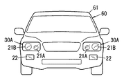
本実施形態の点灯装置10は、自動車などの車両60に搭載される車両用照明装置30(図2及び図3参照)に備えられている。
(2.1) Description of Lighting Device The
点灯装置10は、図1に示すように、2つのコンバータ回路111,112と、温度検出部12と、制御回路13とを備えている。また、点灯装置10は、電源接続用のコネクタCN1と、2つの光源21,22をそれぞれ接続するためのコネクタCN21,CN22とを備えている。
As shown in FIG. 1, the
点灯装置10は、2種類の光源21,22を点灯させるために用いられる。光源21は、例えばすれ違い用(ロービーム用)前照灯として用いられる光源21Aと、走行用(ハイビーム用)前照灯として用いられる光源21Bとを含む(図2参照)。光源22は、例えば車幅灯、DRL(Daytime Running Lights)などの標識灯、又はターンシグナルランプ(turn signal lump)として用いられる光源である。光源21A,21B,22は、例えば、直列又は並列に接続された複数の発光ダイオードからなる。
The
コネクタCN1には、直流電源40からの電源線が接続される。
A power line from the
コネクタCN21には、点灯装置10と光源21(21A,21B)との間を接続する電線が接続される。
An electric wire that connects between the
コネクタCN22には、点灯装置10と光源22との間を接続する電線が接続される。
An electric wire that connects between the
コンバータ回路111の入力端子はコネクタCN1に電気的に接続され、コンバータ回路111の出力端子はコネクタCN21に接続されている。コンバータ回路111は、例えば昇圧型のDC−DCコンバータ回路である。コンバータ回路111は、直流電源40から入力される直流電圧を、光源21に適合した出力(出力電圧又は出力電流)に変換しており、コンバータ回路111の出力OUT1が光源21に供給される。
The input terminal of the
コンバータ回路112の入力端子はコネクタCN1に電気的に接続され、コンバータ回路112の出力端子はコネクタCN22に接続されている。コンバータ回路112は、例えば昇圧型のDC−DCコンバータ回路である。コンバータ回路112は、直流電源40から入力される直流電圧を、光源22に適合した出力(出力電圧又は出力電流)に変換して、コンバータ回路112の出力OUT2が光源22に供給される。
The input terminal of the
温度検出部12は、ケース15(図2参照)の内部の雰囲気の温度(以下、内部温度という。)を検出する。ケース15には、コンバータ回路111,112及び制御回路13が形成された回路基板が収納されている。温度検出部12は、例えばサーミスタからなり、コンバータ回路111,112及び制御回路13が形成された回路基板に実装されている。
The
制御回路13は、コンバータ回路111,112のそれぞれの出力OUT1,OUT2を制御する。制御回路13には、光源21,22のそれぞれについて、温度検出部12によって検出された内部温度が閾値以上になったときに出力を低下させる優先度が、光源21,22の用途に応じて、あらかじめ設定されている。本実施形態では、光源21の用途が前照灯用であり、光源22の用途が標識灯用であるので、車両60の走行に直接的に影響する光源21の方が、光源22よりも重要度が高い。したがって、本実施形態では、高温時に出力を低下させる場合の優先度は、用途の重要度が低い標識灯用の光源22よりも、用途の重要度が高い前照灯用の光源21の方が低い値に設定されている。
The
制御回路13は、温度検出部12によって検出された内部温度が閾値未満であるときは、光源21,22のそれぞれに適合した定格出力(定格電流又は定格電圧)となるように、コンバータ回路111,112のそれぞれの出力OUT1,OUT2を制御する。
When the internal temperature detected by the
制御回路13は、温度検出部12によって検出された内部温度が閾値以上になったときには、光源21,22のうち優先度が高い光源への出力を優先的に低減させるように、コンバータ回路111,112の出力OUT1,OUT2を制御する。
When the internal temperature detected by the
ところで、制御回路13には、光源21,22の用途に応じた優先度が、あらかじめ設定されているが、光源の用途と、光源の定格出力電流の大きさとの両方に基づいた優先度が設定されていてもよい。例えば、用途の重要度合いが同程度の光源が複数ある場合は、用途の重要度合いが同程度の複数の光源の中で、光源の定格出力電流の大きさに基づいて優先度が設定されればよく、定格出力電流の大きさが大きい光源ほど優先度が高く設定されればよい。
By the way, although the priority according to the use of the
(2.2)車両用照明装置の説明
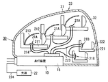
本実施形態の車両用照明装置30は、図2に示すように、点灯装置10と、前照灯用の光源21(21A,21B)と、標識灯用の光源22と、ハウジング33と備える。
(2.2) Description of Vehicle Lighting Device As shown in FIG. 2, the
車両用照明装置30は、例えば自動車などの車両60の前照灯と標識灯とを点灯させる照明装置である。
The
ハウジング33は、前方に開口が設けられたボディ31と、ボディ31の前方の開口部分に取り付けられた透光カバー32とを備えている。車両用照明装置30のハウジング33は、車両60の車体61(図3参照)に取り付けられる。
The housing 33 includes a
ハウジング33の内部には前照灯用の光源21が収容されている。また、ハウジング33の下部には点灯装置10のケース15が取り付けられている。
A
光源21は、ロービーム用前照灯の光源21Aと、ハイビーム用前照灯の光源21Bとを含む。
The
ロービーム用前照灯の光源21Aを構成する複数の発光ダイオードは基台211に取り付けられている。光源21Aが取り付けられる基台211には、レンズ212と、反射板213とがそれぞれ取り付けられている。
A plurality of light emitting diodes constituting the
ハイビーム用前照灯の光源21Bを構成する複数の発光ダイオードは基台221に取り付けられている。光源21Bが取り付けられる基台221には、レンズ222が取り付けられている。
A plurality of light emitting diodes constituting the
標識灯用の光源22はハウジング33の外部に設けられ、光源22と点灯装置10とは電線224を介して電気的に接続されている。
The
(2.3)動作説明
本実施形態の点灯装置10の動作を図4〜図7を参照して説明する。
(2.3) Operation Description The operation of the
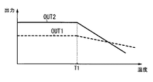
図4は点灯装置10の出力特性を示すグラフである。図4の横軸は温度検出部12によって検出される内部温度、図4の縦軸はコンバータ回路111,112の出力OUT1,OUT2である。
FIG. 4 is a graph showing output characteristics of the
制御回路13は、内部温度が閾値T1未満であるときは、コンバータ回路111,112の出力OUT1,OUT2をそれぞれ光源21,22に適合した定格出力に制御する。なお、図4の例では、コンバータ回路111の出力OUT1の定格値は、コンバータ回路112の出力OUT2の定格値よりも低い値に設定されている。
When the internal temperature is less than the threshold value T1, the
点灯時の回路部品の発熱などによってケース15の内部温度が上昇し、内部温度が閾値T1以上になると、制御回路13は、優先度が高い光源22への出力OUT2を優先的に低減させる。すなわち、内部温度が閾値T1以上になると、制御回路13は、光源22に対応したコンバータ回路112の出力OUT2を、内部温度に比例して一定の割合で低下させる。コンバータ回路112の出力OUT2が低下すると、コンバータ回路112の回路部品での発熱が抑制されるので、ケース15の内部温度の上昇が抑制される。したがって、点灯装置10の回路部品の温度上昇が抑制され、回路部品を保護できる。また、制御回路13は、優先度が高い光源22への出力OUT2を低減させることで、優先度が低い光源21への出力OUT1を、より長い間、定格出力で維持することができる。したがって、優先度が低い、つまり用途の重要度が高い光源21の明るさが暗くなるのを抑制できる。
When the internal temperature of the
一方、内部温度が閾値T1以上かつ閾値T2(T2>T1)未満であるときは、制御回路13は、優先度が低い光源21に対応したコンバータ回路111の出力OUT1を、定格出力のまま維持している。
On the other hand, when the internal temperature is equal to or higher than the threshold T1 and lower than the threshold T2 (T2> T1), the
ケース15の内部温度がさらに上昇して閾値T2以上になると、制御回路13は、優先度が低い光源21に対応したコンバータ回路111の出力OUT1も低下させる。すなわち、内部温度が閾値T2以上になると、制御回路13は、光源21に対応したコンバータ回路111の出力OUT1を、内部温度に比例して一定の割合で低下させる。
When the internal temperature of the
これにより、ケース15の内部温度がさらに上昇して閾値T2以上になったときは、制御回路13は、コンバータ回路111,112の出力OUT1,OUT2を両方共に低下させており、回路部品の発熱を低減して、内部温度のさらなる上昇を抑制することができる。
As a result, when the internal temperature of the
このように、制御回路13は、複数種類の光源21,22のうち優先度が高い光源ほど閾値を低い温度に設定しているので、優先度が高い光源への出力が優先的に低減されることになる。
In this way, the
ところで、制御回路13は、複数種類の光源21,22のうち優先度が高い光源ほど、温度検出部12によって検出された内部温度が閾値以上になったときに、温度上昇に応じて当該光源に出力する電力を低下させる割合を大きくするように構成されてもよい。
By the way, when the internal temperature detected by the
この場合の点灯装置10の動作を図5に基づいて説明する。
The operation of the
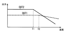
図5は点灯装置10の出力特性を示すグラフであり、図5の横軸は温度検出部12によって検出される内部温度、図5の縦軸はコンバータ回路111,112の出力OUT1,OUT2である。
FIG. 5 is a graph showing the output characteristics of the
制御回路13は、内部温度が閾値T1未満であるときは、コンバータ回路111,112の出力OUT1,OUT2をそれぞれ光源21,22に適合した定格出力に制御する。なお、図5の例では、コンバータ回路111の出力OUT1の定格値は、コンバータ回路112の出力OUT2の定格値よりも低い値に設定されている。
When the internal temperature is less than the threshold value T1, the
点灯時の回路部品の発熱などによってケース15の内部温度が上昇し、内部温度が閾値T1以上になると、制御回路13は、光源21,22への出力OUT1,OUT2をそれぞれ低減させるようにコンバータ回路111,112を制御する。ここで、制御回路13は、光源の優先度が高いほど、内部温度の温度上昇に比例して光源への出力を低下させる割合を大きくしている。本実施形態では、光源21に比べて光源22の方が優先度が高く設定されている。よって、制御回路13は、内部温度が閾値T1以上になったときに、温度上昇に比例してコンバータ回路112の出力OUT2を減少させる割合を、温度上昇に比例してコンバータ回路111の出力OUT1を減少させる割合よりも大きくしている。
When the internal temperature of the
このように、ケース15の内部温度が上昇して閾値T1以上になったときは、制御回路13は、コンバータ回路111,112の出力OUT1,OUT2を両方共に低下させており、回路部品の発熱を低減して、内部温度のさらなる上昇を抑制することができる。
As described above, when the internal temperature of the
しかも、制御回路13は、温度上昇に比例してコンバータ回路112の出力OUT2が減少する割合を、温度上昇に比例してコンバータ回路111の出力OUT1が減少する割合よりも大きくしているので、光源22への出力OUT2を優先的に低減できる。したがって、温度上昇を抑えつつ、内部温度が閾値T1以上になったときに、光源21への出力OUT1が定格出力から減少する割合は、光源22への出力OUT2が定格出力から減少する割合よりも小さくなる。よって、ケース15の内部温度の上昇を抑えつつ、用途の重要度合いが高い光源21の明るさが暗くなりにくいという利点がある。
In addition, the
また、制御回路13は、複数種類の光源21,22のうち優先度が高い光源ほど、閾値を低い温度に設定し、温度検出部12によって検出された内部温度が閾値以上になったときに、温度上昇に応じて光源に出力する電力を低下させる割合を大きくしてもよい。
Further, the
この場合の点灯装置10の動作を図6に基づいて説明する。図6は点灯装置10の出力特性を示すグラフであり、図6の横軸は温度検出部12によって検出される内部温度、図6の縦軸はコンバータ回路111,112の出力OUT1,OUT2である。
The operation of the
制御回路13は、内部温度が閾値T1未満であるときは、コンバータ回路111,112の出力OUT1,OUT2をそれぞれ光源21,22に適合した定格出力に制御する。なお、図6の例では、コンバータ回路111の出力OUT1の定格値は、コンバータ回路112の出力OUT2の定格値よりも低い値に設定されている。
When the internal temperature is less than the threshold value T1, the
点灯時の回路部品の発熱などによってケース15の内部温度が上昇し、内部温度が閾値T1以上になると、制御回路13は、優先度が高い光源22への出力OUT2を優先的に低減させる。すなわち、内部温度が閾値T1以上になると、制御回路13は、光源22に対応したコンバータ回路112の出力OUT2を、内部温度に比例して一定の割合で低下させる。コンバータ回路112の出力OUT2が低下すると、コンバータ回路112の回路部品での発熱が抑制されるので、ケース15の内部温度の上昇が抑制される。したがって、点灯装置10の回路部品の温度上昇が抑制され、回路部品を保護できる。また、制御回路13は、優先度が高い光源22への出力OUT2を低減させることで、優先度が低い光源21への出力OUT1を、より長い間、定格出力で維持することができる。
When the internal temperature of the
一方、内部温度が閾値T1以上かつ閾値T2(T2>T1)未満であるときは、制御回路13は、優先度が低い光源21に対応したコンバータ回路111の出力OUT1を、定格出力のまま維持している。
On the other hand, when the internal temperature is equal to or higher than the threshold T1 and lower than the threshold T2 (T2> T1), the
ケース15の内部温度がさらに上昇して閾値T2以上になると、制御回路13は、優先度が低い光源21に対応したコンバータ回路111の出力OUT1も低下させる。すなわち、内部温度が閾値T2以上になると、制御回路13は、光源21に対応したコンバータ回路111の出力OUT1を、内部温度に比例して一定の割合で低下させる。ここで、制御回路13は、光源の優先度が高いほど、内部温度の温度上昇に比例して光源への出力を低下させる割合を大きくしている。すなわち、制御回路13は、温度上昇に比例してコンバータ回路112の出力OUT2を減少させる割合を、温度上昇に比例してコンバータ回路111の出力OUT1を減少させる割合よりも大きくしている。
When the internal temperature of the
これにより、ケース15の内部温度がさらに上昇して閾値T2以上になったときは、制御回路13は、コンバータ回路111,112の出力OUT1,OUT2を両方共に低下させており、回路部品の発熱を低減して、内部温度のさらなる上昇を抑制することができる。また、制御回路13は、温度上昇に比例してコンバータ回路112の出力OUT2が減少する割合を、温度上昇に比例してコンバータ回路111の出力OUT1が減少する割合よりも大きくしているので、光源22への出力OUT2を優先的に低減させることができる。したがって、ケース15の内部温度の上昇を抑えつつ、用途の重要度合いが高い光源21の明るさが暗くなりにくいという利点がある。
As a result, when the internal temperature of the
また、制御回路13は、温度検出部12によって検出された内部温度が停止温度T3,T4以上になったときに、優先度が高い順番に光源21,22への出力OUT1,OUT2を停止させるように、コンバータ回路111,112の出力を制御してもよい。なお、停止温度T3,T4はそれぞれ閾値T1,T2よりも高い温度に設定されている。ここで、閾値T1,T2と停止温度T3,T4の関係は、T1<T2<T3<T4である。
In addition, the
この場合の点灯装置10の動作を図7に基づいて説明する。なお、内部温度がT3以上になったときに光源22への出力OUT2を停止させ、内部温度がT4以上になったときに光源21への出力OUT1を停止させる動作を除いては、図4の動作と同様である。
The operation of the
制御回路13は、内部温度が閾値T1未満であるときは、コンバータ回路111,112の出力OUT1,OUT2をそれぞれ光源21,22に適合した定格出力に制御する。なお、図7の例では、コンバータ回路111の出力OUT1の定格値は、コンバータ回路112の出力OUT2の定格値よりも低い値に設定されている。
When the internal temperature is less than the threshold value T1, the
点灯時の回路部品の発熱などによってケース15の内部温度が上昇し、内部温度が閾値T1以上になると、制御回路13は、優先度が高い光源22への出力OUT2を優先的に低減させる。すなわち、内部温度が閾値T1以上になると、制御回路13は、光源22に対応したコンバータ回路112の出力OUT2を、内部温度に比例して一定の割合で低下させる。コンバータ回路112の出力OUT2が低下すると、コンバータ回路112の回路部品での発熱が抑制されるので、ケース15の内部温度の上昇が抑制される。したがって、点灯装置10の回路部品の温度上昇が抑制され、回路部品を保護できる。また、制御回路13は、優先度が高い光源22への出力OUT2を低減させることで、優先度が低い光源21への出力OUT1を、より長い間、定格出力で維持することができる。
When the internal temperature of the
一方、内部温度が閾値T1以上かつ閾値T2(T2>T1)未満であるときは、制御回路13は、優先度が低い光源21に対応したコンバータ回路111の出力OUT1を、定格出力のまま維持している。
On the other hand, when the internal temperature is equal to or higher than the threshold T1 and lower than the threshold T2 (T2> T1), the
ケース15の内部温度がさらに上昇して閾値T2以上になると、制御回路13は、優先度が低い光源21に対応したコンバータ回路111の出力OUT1も低下させる。すなわち、内部温度が閾値T2以上になると、制御回路13は、光源21に対応したコンバータ回路111の出力OUT1を、内部温度に比例して一定の割合で低下させる。
When the internal temperature of the
ケース15の内部温度がさらに上昇して停止温度T3(T3>T2)以上になると、制御回路13は、優先度が高い光源22に対応したコンバータ回路112の出力OUT2を停止させる。すなわち、内部温度が停止温度T3以上になると、制御回路13は、優先度が高い光源22に対応したコンバータ回路112の出力OUT2を停止させて、光源22を消灯させる。これにより、ケース15の内部温度の上昇が抑えられるため、優先度が低い光源21、つまり用途の重要度合いが高い光源21の明るさが暗くなりにくいという利点がある。
When the internal temperature of the
また、ケース15の内部温度がさらに上昇して停止温度T4以上になると、制御回路13は、優先度が低い光源21に対応したコンバータ回路111の出力OUT1を停止させる。すなわち、内部温度が停止温度T4以上になると、制御回路13は、優先度が低い光源21に対応したコンバータ回路111の出力OUT1を停止させて、光源21を消灯させる。これにより、ケース15の内部温度の上昇が抑えられるため、回路部品を保護することができる。
Further, when the internal temperature of the
なお、制御回路13が、図5及び図6に示した制御動作を行う場合に、内部温度が閾値よりも高い停止温度以上になったときに、優先度が高い順番に光源への出力を停止させるように、コンバータ回路111,112の出力を制御してもよい。このような制御を制御回路13が行うことで、回路部品を保護できる。
When the
(3)効果
上述のように、第1の態様の点灯装置10は、複数の電力変換回路(コンバータ回路111,112)と、制御回路13と、温度検出部12とを備える。複数の電力変換回路にはそれぞれ複数種類の光源21,22が接続されている。制御回路13は、複数の電力変換回路のそれぞれの出力を制御する。温度検出部12は、複数の電力変換回路及び制御回路13を収納するケース15の内部温度を検出する。制御回路13には、複数種類の光源21,22のそれぞれについて、温度検出部12によって検出された内部温度が閾値以上になったときに出力を低下させる優先度が、当該光源の用途に応じて設定されている。制御回路13は、温度検出部12によって検出された内部温度が閾値以上になったときに、複数種類の光源21,22のうち優先度が高い光源への出力を優先的に低減させるように、複数の電力変換回路の出力を制御するように構成されている。
(3) Effect As described above, the
ケース15の内部温度が閾値以上になったときに、制御回路13は、優先度が高い光源への出力を優先的に低減させているので、優先度が高い光源に対応した電力変換回路での発熱が抑制され、ケース15の内部温度の上昇を抑制できる。したがって、内部温度の上昇を抑えつつ、優先度が低い光源への出力が低減されにくくなる、という効果がある。ここにおいて、優先度は光源の用途に応じて設定されており、用途の重要度合いが高い光源ほど優先度が低めに設定されていれば、用途の重要度合いが高い光源への出力が低減されにくくなる、という効果がある。
When the internal temperature of the
第2の態様の点灯装置10では、第1の態様において、制御回路13には、複数種類の光源21,22のそれぞれについて、当該光源の用途と、当該光源の定格出力電流の大きさとの両方に基づいて優先度が設定されてもよい。この構成は、点灯装置10に必須の構成では無く、適宜省略が可能である。また、この構成は実施形態1の他の構成及び変形例と適宜組み合わせることが可能である。
In the
例えば、定格出力電流の大きさが大きい光源ほど優先度が高く設定されていれば、定格出力電流の大きさが大きい光源への出力が優先的に低減される。定格出力電流の大きさが相対的に大きい光源への出力を低減させた場合、定格出力電流の大きさが相対的に小さい光源への出力を低減させた場合に比べて、電力変換回路での発熱を低減する効果が大きくなる。よって、ケース15の内部温度の上昇を抑制する効果が高くなり、優先度が低い光源への出力が低減されにくくなる。
For example, if the priority is set higher for a light source having a larger rated output current, the output to the light source having a larger rated output current is preferentially reduced. When the output to a light source with a relatively large rated output current is reduced, the output of the power conversion circuit is smaller than when the output to a light source with a relatively small rated output current is reduced. The effect of reducing heat generation is increased. Therefore, the effect of suppressing an increase in the internal temperature of the
第3の態様の点灯装置10では、第1又は第2の態様において、制御回路13が、複数種類の光源21,22のうち優先度が高い光源ほど閾値を低い温度に設定するように構成されてもよい。この構成は、点灯装置10に必須の構成では無く、適宜省略が可能である。また、この構成は実施形態1の他の構成及び変形例と適宜組み合わせることが可能である。
In the
これにより、優先度が高い光源ほど低い温度で出力が抑制されるため、優先度が高い光源への出力を優先的に低減できる。 Thereby, since the output is suppressed at a lower temperature as the light source has a higher priority, the output to the light source with a higher priority can be preferentially reduced.
第4の態様の点灯装置10では、第1又は第2の態様において、制御回路13が、複数種類の光源21,22のうち優先度が高い光源ほど、温度検出部12によって検出された内部温度が閾値以上になったときに、温度上昇に応じて当該光源に出力する電力を低下させる割合を大きくするように構成されてもよい。この構成は、点灯装置10に必須の構成では無く、適宜省略が可能である。また、この構成は実施形態1の他の構成及び変形例と適宜組み合わせることが可能である。
In the
これにより、優先度が高い光源ほど、温度上昇に応じて当該光源に出力する電力を低下させる割合が大きくなるため、優先度が高い光源への出力を優先的に低減できる。 Thereby, since the ratio which reduces the electric power output to the said light source according to a temperature rise becomes large, the output to a light source with high priority can be reduced preferentially.
第5の態様の点灯装置10では、第1又は第2の態様において、制御回路13が、複数種類の光源のうち優先度が高い光源ほど、閾値を低い温度に設定し、温度検出部12によって検出された内部温度が閾値以上になったときに、温度上昇に応じて当該光源に出力する電力を低下させる割合を大きくするように構成されてもよい。この構成は、点灯装置10に必須の構成では無く、適宜省略が可能である。また、この構成は実施形態1の他の構成及び変形例と適宜組み合わせることが可能である。
In the
これにより、優先度が高い光源ほど低い温度で出力が抑制されるため、優先度が高い光源への出力を優先的に低減できる。また、優先度が高い光源ほど、温度上昇に応じて当該光源に出力する電力を低下させる割合が大きくなるため、優先度が高い光源への出力を優先的に低減できる。 Thereby, since the output is suppressed at a lower temperature as the light source has a higher priority, the output to the light source with a higher priority can be preferentially reduced. Moreover, since the ratio which reduces the electric power output to the said light source according to temperature rise, the output to a light source with high priority can be preferentially reduced, so that a light source with high priority becomes high.
第6の態様の点灯装置10では、第1〜第5の態様において、制御回路13は、温度検出部12によって検出された内部温度が、閾値よりも高い停止温度以上になったときに、優先度が高い順番に光源21,22への出力を停止させるように、複数の電力変換回路(コンバータ回路111,112)の出力を制御してもよい。この構成は、点灯装置10に必須の構成では無く、適宜省略が可能である。また、この構成は実施形態1の他の構成及び変形例と適宜組み合わせることが可能である。
In the
ケース15の内部温度が停止温度以上になると、制御回路13は、優先度が高い順番に光源21,22への出力を停止させているため、内部温度の上昇を抑えることができ、また優先度が高い光源に比べて優先度が低い光源へより長く出力を供給できる。
When the internal temperature of the
また、第7の態様の点灯装置10では、第1〜第6の態様において、複数種類の光源21(21A,21B),22のそれぞれが発光ダイオードであることも好ましい。この構成は、点灯装置10に必須の構成では無く、適宜省略が可能である。また、この構成は実施形態1の他の構成及び変形例と適宜組み合わせることが可能である。
In the
また、第8の態様の車両用照明装置30は、第1〜第7の態様の点灯装置10と、複数種類の光源21,22と、ハウジング33とを備えている。複数種類の光源21,22は点灯装置10によって点灯される。ハウジング33は、複数種類の光源21,22の少なくとも一部と点灯装置10とを保持して車両60に取り付けられる。
The
これにより、ケース15の内部温度が閾値以上になったときに、光源21,22の用途に応じた優先度にしたがって光源への出力を低減することができ、内部温度の上昇を抑制できる。
Thereby, when the internal temperature of
(4)変形例
以下に、上記実施形態の変形例に係る点灯装置及び車両用照明装置を列記する。なお、以下に説明する変形例の各構成は、上記実施形態で説明した各構成と適宜組み合わせて適用可能である。
(4) Modification Below, the lighting device and vehicle lighting device which concern on the modification of the said embodiment are listed. In addition, each structure of the modified example demonstrated below is applicable in combination with each structure demonstrated in the said embodiment suitably.
本実施形態の点灯装置10では、電力変換回路であるコンバータ回路111,112が、昇圧型のDC−DCコンバータ回路であったが、電力変換回路は、降圧型のDC−DCコンバータ回路でもよいし、昇降圧型のDC−DCコンバータ回路でもよい。
In the
本実施形態の点灯装置10は、2つの光源21,22がそれぞれ接続された2つの電力変換回路(コンバータ回路111,112)を備えているが、3つ以上の光源がそれぞれ接続される3つ以上の電力変換回路を備えていてもよい。この場合、制御回路13には、3つ以上の光源のそれぞれについて用途に応じた優先度が設定されていればよい。
The
本実施形態の点灯装置10では、優先度が高く設定された光源22の方が、優先度が低く設定された光源21よりも定格出力が大きいが、優先度が高く設定された光源22の方が、優先度が低く設定された光源21よりも定格出力が小さい場合もある。すなわち、制御回路13には、定格出力の大小に関係無く、光源21,22の用途に応じて優先度が設定されていればよい。
In the
本実施形態の点灯装置10は車両用の照明装置に用いられており、優先度が高い光源が前照灯用の光源であり、優先度が低い光源が標識用の光源であったが、光源の種類は実施形態に限定されない。例えば優先度が高い光源がロービーム用前照灯の光源であり、優先度が低い光源がハイビーム用前照灯の光源であってもよい。また、優先度は3段階以上あってもよく、例えば最も優先度が高い光源がロービーム用前照灯の光源、次に優先度が高い光源がハイビーム用前照灯の光源、最も優先度が低い光源が標識灯用の光源であってもよい。
The
また、本実施形態の点灯装置10の用途は車両用に限定されず、1つの点灯装置10で複数種類の光源を点灯させる照明装置であれば、他の用途にも適用可能であり、例えば鉄道車両や航空機などに用いられる前照灯、標識灯などの点灯装置でもよい。
In addition, the use of the
(実施形態2)
以下、実施形態2に係る点灯装置10A、及び点灯装置10Aを備えた車両用照明装置30Aについて図8を参照して説明する。
(Embodiment 2)
Hereinafter, the
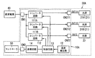
本実施形態の点灯装置10Aは、実施形態1で説明した点灯装置10の構成に加えて、通信回路14(取得部)を、さらに備えている。また、コンバータ回路111の代わりに、コンバータ回路111A,111Bを備えている。また、点灯装置10Aは、光源21A,21Bをそれぞれ接続するためのコネクタCN211,CN212と、コントローラ50との間の通信線が接続されるコネクタCN3を備えている。なお、通信回路14、コンバータ回路111A,111B、コネクタCN211,CN212,CN3以外は実施形態1の点灯装置10と同様であるから、同一の構成要素には同一の符号を付して、その説明は省略する。
10 A of lighting devices of this embodiment are further provided with the communication circuit 14 (acquisition part) in addition to the structure of the
コンバータ回路111Aは、例えば昇圧型のDC−DCコンバータ回路である。コンバータ回路111Aは、直流電源40から入力される直流電圧を、ロービーム用前照灯の光源21Aに適合した出力(出力電圧又は出力電流)に変換しており、コンバータ回路111の出力OUT11が光源21Aに供給される。
The
コンバータ回路111Bは、例えば昇圧型のDC−DCコンバータ回路である。コンバータ回路111Bは、直流電源40から入力される直流電圧を、ハイビーム用前照灯の光源21Bに適合した出力(出力電圧又は出力電流)に変換しており、コンバータ回路111Bの出力OUT12が光源21Bに供給される。
The converter circuit 111B is, for example, a step-up DC-DC converter circuit. The converter circuit 111B converts the DC voltage input from the
通信回路14は、コネクタCN3に接続される通信線を介してコントローラ50に接続されている。コントローラ50は、車両60(図3参照)の全般的な制御を行うコントローラであり、通信回路14はコントローラ50から車両情報を取得する。車両情報は、例えば、車両の蛇角情報、車速情報、周囲の照度情報、姿勢情報などである。コントローラ50は、例えばステアリングの操舵角を検出するセンサから蛇角情報を取得する。コントローラ50は、例えばタイヤの回転量を検出するセンサから車速情報を取得する。コントローラ50は、例えば車両に設けられた明るさセンサから周囲の照度情報を取得する。コントローラ50は、例えば車両に設けられた加速度センサから車体61の傾きなどの姿勢情報を取得する。
The
制御回路13には、実施形態1で説明した優先度とは別に、複数種類の光源21A,21B,22のそれぞれについて、車両情報に基づいて出力を低下させる場合の優先順位が、当該光源の用途に応じて設定されている。
In the
制御回路13は、通信回路14によって取得された車両情報に基づいて、優先順位が高い光源から当該光源への出力を低減させるように、コンバータ回路111A,111B,112を制御する。つまり、制御回路13は、温度検出器12によって検出された内部温度とは関係無く、車両情報に基づいて、優先順位が高い光源から当該光源への出力を低減させるように、コンバータ回路111A,111B,112を制御する。なお、制御回路13は、温度検出部12によって検出された内部温度が閾値以上になったときは、実施形態1と同様に、優先度が高い光源への出力を優先的に低減させるように、複数の電力変換回路の出力を制御している。
Based on the vehicle information acquired by the
制御回路13は、車両情報に含まれる蛇角情報をもとに、蛇角が所定角度以上(例えば15度以上)であると判断すると、車体61が曲がっていると判断して、ハイビーム用の前照灯の光源21Bへの出力OUT12を優先的に低減させる。この場合、ロービーム用前照灯の光源21Aへの出力OUT11と、標識灯の光源22への出力OUT2は低減されにくくなるため、ロービーム用前照灯及び標識灯の明るさが暗くなりにくくなる。
When the
また、制御回路13は、車両情報に含まれる車速情報をもとに、車速が所定速度以上(例えば30km/h以上)であると判断すると、ロービーム用前照灯の光源21Aへの出力OUT11と、標識灯の光源22への出力OUT2とを優先的に低減させる。この場合、ハイビーム用前照灯の光源21Bへの出力OUT12は低減されにくくなるため、ハイビーム用前照灯の明るさが暗くなりにくくなる。したがって、所定速度以上で走行している場合に、ハイビーム用前照灯の明るさが暗くなりにくいから、運転手が遠方を見やすくなる。
When the
また、制御回路13は、車両情報に含まれる照度情報をもとに、周囲照度が所定の照度よりも暗い場合には、標識灯などの光源22への出力OUT2を優先的に低減させる。この場合、ロービーム用前照灯の光源21Aへの出力OUT11、及びハイビーム用前照灯の光源21Bへの出力OUT12は低減されにくくなるため、ロービーム用前照灯及びハイビーム用前照灯の明るさが暗くなりにくくなる。周囲が暗い場合には前照灯の光源21が明るく点灯していれば、前方からは車両の存在が確認できるので、標識灯などの光源22の明るさが多少暗くなっても、走行への支障は少ない。よって、標識灯などの光源22の明るさを多少暗くしても、前照灯用の光源21の明るさを暗くなりにくくすることで、走行への悪影響が低減される。
Further, based on the illuminance information included in the vehicle information, the
また、制御回路13は、車両情報に含まれる姿勢情報をもとに、車体61の傾斜角が所定角度以上である場合には、ハイビーム用前照灯の光源21Bへの出力OUT12と、標識灯の光源22への出力OUT2とを優先的に低減させる。この場合、ロービーム用前照灯の光源21Aへの出力OUT11は低減されにくくなるので、車体61が路面に対して傾斜している場合でも、ロービーム用前照灯の明るさが暗くなりにくく、路面の状態を目視で確認しやすくなる。
Further, based on the attitude information included in the vehicle information, the
なお、実施形態2で説明した構成(変形例を含む)は、実施形態1で説明した構成(変形例を含む)と適宜組み合わせて適用である。つまり、制御回路13は、内部温度が閾値以上になったときに出力を優先的に低減させる光源を、取得部によって取得された車両情報に基づいた優先順位にしたがって決定してもよい。すなわち、実施形態1で説明した優先度が、複数の走行状態のそれぞれで、別個に設定されていてもよい。
Note that the configuration (including modifications) described in the second embodiment is applied in appropriate combination with the configuration (including modifications) described in the first embodiment. That is, the
以上のように、第9の態様の車両用照明装置30は、第8の態様において、車両の走行状態に関する車両情報を取得する取得部(通信回路14)を、さらに備えてもよい。
As described above, the
制御回路13には、複数種類の光源21A,21B,22のそれぞれについて、車両情報に基づいて出力を低下させる場合の優先順位が、当該光源の用途に応じて設定されている。制御回路13は、取得部によって取得された車両情報に基づいて、優先順位が高い光源から当該光源への出力を低減させるように、当該光源に対応した電力変換回路(インバータ回路111A,111B,112)の出力を制御するように構成されている。
In the
これにより、複数種類の光源への出力を、車両情報に応じて設定される優先順位にしたがって、優先順位が高い光源から当該光源への出力を低減させることができる。 Thereby, according to the priority set according to vehicle information, the output to the said light source from a light source with a high priority can be reduced for the output to a multiple types of light source.
第10の態様の点灯装置は、第9の態様において、車両情報が、車両の蛇角情報、車速情報、周囲の照度情報、姿勢情報のうちの少なくとも1つを含むことが好ましい。 In the lighting device of the tenth aspect, in the ninth aspect, it is preferable that the vehicle information includes at least one of vehicle snake angle information, vehicle speed information, ambient illuminance information, and attitude information.
10,10A 点灯装置
12 温度検出部
13 制御回路
14 通信回路(取得部)
15 ケース
21,21A,21B,22 光源
30,30A 車両用照明装置
33 ハウジング
60 車両
61 車体
111,111A,111B,112 コンバータ回路(電力変換回路)
10,
15
Claims (10)
前記複数の電力変換回路のそれぞれの出力を制御する制御回路と、
前記複数の電力変換回路及び前記制御回路が収納されたケースの内部温度を検出する温度検出部とを備え、
前記制御回路には、前記複数種類の光源のそれぞれについて、前記温度検出部によって検出された前記内部温度が閾値以上になったときに出力を低下させる優先度が、当該光源の用途に応じて設定されており、
前記制御回路は、前記温度検出部によって検出された前記内部温度が閾値以上になったときに、前記複数種類の光源のうち前記優先度が高い光源への出力を優先的に低減させるように、前記複数の電力変換回路の出力を制御するように構成された、
点灯装置。 A plurality of power conversion circuits each having a plurality of types of light sources connected thereto;
A control circuit for controlling the output of each of the plurality of power conversion circuits;
A temperature detection unit that detects an internal temperature of a case in which the plurality of power conversion circuits and the control circuit are housed;
In the control circuit, for each of the plurality of types of light sources, a priority for lowering the output when the internal temperature detected by the temperature detection unit is equal to or higher than a threshold is set according to the use of the light source. Has been
The control circuit, when the internal temperature detected by the temperature detection unit is equal to or higher than a threshold, to preferentially reduce the output to the light source having a high priority among the plurality of types of light sources, Configured to control outputs of the plurality of power conversion circuits;
Lighting device.
請求項1に記載の点灯装置。 In the control circuit, a priority is set for each of the plurality of types of light sources based on both the use of the light source and the rated output current of the light source.
The lighting device according to claim 1.
請求項1又は2に記載の点灯装置。 The control circuit is configured to set the threshold to a lower temperature for a light source having a higher priority among the plurality of types of light sources,
The lighting device according to claim 1 or 2.
請求項1又は2に記載の点灯装置。 The control circuit outputs a light source having a higher priority among the plurality of types of light sources to the light source in response to a temperature rise when the internal temperature detected by the temperature detection unit is equal to or higher than a threshold value. Configured to increase the rate of power reduction,
The lighting device according to claim 1 or 2.
請求項1又は2に記載の点灯装置。 The control circuit sets the threshold value to a lower temperature for the higher priority light source among the plurality of types of light sources, and when the internal temperature detected by the temperature detection unit is equal to or higher than the threshold value, It was configured to increase the rate of reducing the power output to the light source in accordance with the temperature rise,
The lighting device according to claim 1 or 2.
請求項1〜5のいずれか1項に記載の点灯装置。 When the internal temperature detected by the temperature detection unit is equal to or higher than a stop temperature higher than the threshold, the control circuit stops output to the light source in order of priority. Controlling outputs of the plurality of power conversion circuits;
The lighting device according to any one of claims 1 to 5.
請求項1〜6のいずれか1項に記載の点灯装置。 Each of the plurality of types of light sources is a light emitting diode.
The lighting device according to any one of claims 1 to 6.
車両用照明装置。 A vehicle that holds the lighting device according to any one of claims 1 to 7, the plurality of types of light sources that are turned on by the lighting device, at least some of the plurality of types of light sources, and the lighting device. And a housing attached to the
Vehicle lighting device.
前記制御回路には、前記複数種類の光源のそれぞれについて、前記車両情報に基づいて出力を低下させる場合の優先順位が、当該光源の用途に応じて設定されており、
前記制御回路は、前記取得部によって取得された前記車両情報に基づいて、前記優先順位が高い光源から当該光源への出力を低減させるように、当該光源に対応した前記電力変換回路の出力を制御するように構成された、
請求項8に記載の車両用照明装置。 An acquisition unit for acquiring vehicle information related to the running state of the vehicle;
In the control circuit, for each of the plurality of types of light sources, a priority order in the case of reducing the output based on the vehicle information is set according to the use of the light source,
The control circuit controls the output of the power conversion circuit corresponding to the light source so as to reduce the output from the light source having a high priority to the light source based on the vehicle information acquired by the acquisition unit. Configured to
The vehicle lighting device according to claim 8.
請求項9に記載の車両用照明装置。 The vehicle information includes at least one of snake angle information, vehicle speed information, ambient illuminance information, and posture information.
The vehicle lighting device according to claim 9.
Priority Applications (4)
| Application Number | Priority Date | Filing Date | Title |
|---|---|---|---|
| JP2016088591A JP6697737B2 (en) | 2016-04-26 | 2016-04-26 | Lighting device and vehicle lighting device including the same |
| US15/479,411 US9884582B2 (en) | 2016-04-26 | 2017-04-05 | Lighting device and vehicle lighting system with same |
| DE102017107647.6A DE102017107647A1 (en) | 2016-04-26 | 2017-04-10 | LIGHTING DEVICE AND VEHICLE LIGHTING SYSTEM THEREWITH |
| CN201710281137.2A CN107426852B (en) | 2016-04-26 | 2017-04-26 | Lighting device and vehicle lighting system having the same |
Applications Claiming Priority (1)
| Application Number | Priority Date | Filing Date | Title |
|---|---|---|---|
| JP2016088591A JP6697737B2 (en) | 2016-04-26 | 2016-04-26 | Lighting device and vehicle lighting device including the same |
Publications (2)
| Publication Number | Publication Date |
|---|---|
| JP2017199520A true JP2017199520A (en) | 2017-11-02 |
| JP6697737B2 JP6697737B2 (en) | 2020-05-27 |
Family
ID=60021465
Family Applications (1)
| Application Number | Title | Priority Date | Filing Date |
|---|---|---|---|
| JP2016088591A Active JP6697737B2 (en) | 2016-04-26 | 2016-04-26 | Lighting device and vehicle lighting device including the same |
Country Status (4)
| Country | Link |
|---|---|
| US (1) | US9884582B2 (en) |
| JP (1) | JP6697737B2 (en) |
| CN (1) | CN107426852B (en) |
| DE (1) | DE102017107647A1 (en) |
Cited By (8)
| Publication number | Priority date | Publication date | Assignee | Title |
|---|---|---|---|---|
| JPWO2022131139A1 (en) * | 2020-12-15 | 2022-06-23 | ||
| KR20230098274A (en) * | 2020-11-27 | 2023-07-03 | 발레오 비젼 | Operating method of vehicle lighting device and vehicle lighting device |
| JP2023534819A (en) * | 2020-07-20 | 2023-08-14 | ヴァレオ ビジョン | Automotive lighting device operating method and automotive lighting device |
| WO2023243673A1 (en) * | 2022-06-14 | 2023-12-21 | 市光工業株式会社 | Control device for vehicle lamp, vehicle lamp, and computer-readable non-transitory recording medium storing program |
| JP2023554141A (en) * | 2020-12-21 | 2023-12-26 | ヴァレオ ビジョン | Lighting assembly with fail-safe mode for low beam function |
| JP2023554131A (en) * | 2020-12-21 | 2023-12-26 | ヴァレオ ビジョン | Lighting assembly to perform multiple lighting functions |
| KR102725098B1 (en) * | 2023-11-30 | 2024-11-01 | 에스엘 주식회사 | Lamp for vehicle and control method of Lamp for vehicle |
| JP2025510998A (en) * | 2022-03-31 | 2025-04-15 | ヴァレオ ビジョン | Method for controlling a light-emitting device - Patents.com |
Families Citing this family (6)
| Publication number | Priority date | Publication date | Assignee | Title |
|---|---|---|---|---|
| JP6887106B2 (en) * | 2016-09-08 | 2021-06-16 | パナソニックIpマネジメント株式会社 | Lighting devices, lighting fixtures and vehicles equipped with them |
| US10343590B2 (en) * | 2017-05-31 | 2019-07-09 | Valeo North America, Inc. | Active headlight system and method |
| DE102017112076A1 (en) * | 2017-06-01 | 2018-12-06 | Osram Opto Semiconductors Gmbh | OPTOELECTRONIC COMPONENT AND METHOD FOR MANUFACTURING AN OPTOELECTRONIC COMPONENT |
| KR102220950B1 (en) * | 2019-07-31 | 2021-02-26 | 엘지전자 주식회사 | Method for controlling vehicle in autonomous driving system and apparatus thereof |
| DE102021100092A1 (en) * | 2021-01-06 | 2022-07-07 | HELLA GmbH & Co. KGaA | Headlamp assembly and lighting method for illuminating an area surrounding a vehicle |
| GB2613141A (en) * | 2021-10-01 | 2023-05-31 | Simmtronic Ltd | Lighting system |
Citations (4)
| Publication number | Priority date | Publication date | Assignee | Title |
|---|---|---|---|---|
| JP2005324657A (en) * | 2004-05-13 | 2005-11-24 | Toyota Motor Corp | Vehicle headlamp device |
| JP2009154748A (en) * | 2007-12-27 | 2009-07-16 | Koito Mfg Co Ltd | Lighting control device of vehicular lighting fixture |
| JP2009241921A (en) * | 2008-03-13 | 2009-10-22 | Koito Mfg Co Ltd | Headlamp for vehicle |
| US9237623B1 (en) * | 2015-01-26 | 2016-01-12 | Ketra, Inc. | Illumination device and method for determining a maximum lumens that can be safely produced by the illumination device to achieve a target chromaticity |
Family Cites Families (2)
| Publication number | Priority date | Publication date | Assignee | Title |
|---|---|---|---|---|
| JP2004276739A (en) * | 2003-03-14 | 2004-10-07 | Koito Mfg Co Ltd | Vehicle lighting |
| ITRM20130247A1 (en) * | 2013-04-24 | 2014-10-25 | Piaggio & C Spa | CIRCUIT AND METHOD OF CONTROL OF AN EXTERNAL LED LIGHTING UNIT OF A VEHICLE |
-
2016
- 2016-04-26 JP JP2016088591A patent/JP6697737B2/en active Active
-
2017
- 2017-04-05 US US15/479,411 patent/US9884582B2/en not_active Expired - Fee Related
- 2017-04-10 DE DE102017107647.6A patent/DE102017107647A1/en not_active Withdrawn
- 2017-04-26 CN CN201710281137.2A patent/CN107426852B/en active Active
Patent Citations (4)
| Publication number | Priority date | Publication date | Assignee | Title |
|---|---|---|---|---|
| JP2005324657A (en) * | 2004-05-13 | 2005-11-24 | Toyota Motor Corp | Vehicle headlamp device |
| JP2009154748A (en) * | 2007-12-27 | 2009-07-16 | Koito Mfg Co Ltd | Lighting control device of vehicular lighting fixture |
| JP2009241921A (en) * | 2008-03-13 | 2009-10-22 | Koito Mfg Co Ltd | Headlamp for vehicle |
| US9237623B1 (en) * | 2015-01-26 | 2016-01-12 | Ketra, Inc. | Illumination device and method for determining a maximum lumens that can be safely produced by the illumination device to achieve a target chromaticity |
Cited By (18)
| Publication number | Priority date | Publication date | Assignee | Title |
|---|---|---|---|---|
| JP7760576B2 (en) | 2020-07-20 | 2025-10-27 | ヴァレオ ビジョン | Method for operating an automobile lighting device and automobile lighting device |
| JP2023534819A (en) * | 2020-07-20 | 2023-08-14 | ヴァレオ ビジョン | Automotive lighting device operating method and automotive lighting device |
| JP7600400B2 (en) | 2020-11-27 | 2024-12-16 | ヴァレオ ビジョン | Method for operating a lighting device of a motor vehicle and lighting device of a motor vehicle - Patents.com |
| KR20230098274A (en) * | 2020-11-27 | 2023-07-03 | 발레오 비젼 | Operating method of vehicle lighting device and vehicle lighting device |
| KR102866232B1 (en) * | 2020-11-27 | 2025-09-29 | 발레오 비젼 | Method of operating a vehicle lighting device and a vehicle lighting device |
| JP2023550999A (en) * | 2020-11-27 | 2023-12-06 | ヴァレオ ビジョン | Method for operating a motor vehicle lighting system and motor vehicle lighting system |
| US12215836B2 (en) | 2020-12-15 | 2025-02-04 | Koito Manufacturing Co., Ltd. | Vehicular headlight |
| JPWO2022131139A1 (en) * | 2020-12-15 | 2022-06-23 | ||
| JP7654015B2 (en) | 2020-12-15 | 2025-03-31 | 株式会社小糸製作所 | Vehicle headlights |
| CN116583434A (en) * | 2020-12-15 | 2023-08-11 | 株式会社小糸制作所 | Vehicle Headlamps |
| WO2022131139A1 (en) * | 2020-12-15 | 2022-06-23 | 株式会社小糸製作所 | Vehicular headlight |
| JP2023554141A (en) * | 2020-12-21 | 2023-12-26 | ヴァレオ ビジョン | Lighting assembly with fail-safe mode for low beam function |
| JP2023554131A (en) * | 2020-12-21 | 2023-12-26 | ヴァレオ ビジョン | Lighting assembly to perform multiple lighting functions |
| US12496960B2 (en) | 2020-12-21 | 2025-12-16 | Valeo Vision | Light assembly for performing several lighting functions |
| JP2025510998A (en) * | 2022-03-31 | 2025-04-15 | ヴァレオ ビジョン | Method for controlling a light-emitting device - Patents.com |
| JP2023182277A (en) * | 2022-06-14 | 2023-12-26 | 市光工業株式会社 | Vehicle lighting control device, vehicle lighting, and program |
| WO2023243673A1 (en) * | 2022-06-14 | 2023-12-21 | 市光工業株式会社 | Control device for vehicle lamp, vehicle lamp, and computer-readable non-transitory recording medium storing program |
| KR102725098B1 (en) * | 2023-11-30 | 2024-11-01 | 에스엘 주식회사 | Lamp for vehicle and control method of Lamp for vehicle |
Also Published As
| Publication number | Publication date |
|---|---|
| US20170305328A1 (en) | 2017-10-26 |
| DE102017107647A1 (en) | 2017-10-26 |
| JP6697737B2 (en) | 2020-05-27 |
| CN107426852A (en) | 2017-12-01 |
| US9884582B2 (en) | 2018-02-06 |
| CN107426852B (en) | 2020-10-16 |
Similar Documents
| Publication | Publication Date | Title |
|---|---|---|
| JP6697737B2 (en) | Lighting device and vehicle lighting device including the same | |
| US7205680B2 (en) | Vehicular lamp | |
| US7173375B2 (en) | Vehicular lamp | |
| US20150338045A1 (en) | Vehicle headlight and alert system | |
| US10144341B2 (en) | Low beam intensity control unit | |
| US20040178737A1 (en) | Vehicular lamp | |
| JP2016199083A (en) | Vehicle lighting | |
| JP2008265469A (en) | Vehicular headlight device | |
| CN107889305A (en) | Solid state light emitter lamp device, ligthing paraphernalia, on-vehicle lamp and two-wheeled vehicle | |
| JP2009302296A (en) | Light-emitting diode driving device and illumination device using it, illumination device for in vehicle interior, and illumination device for vehicle | |
| JP2008060604A (en) | Automotive headlamp | |
| JP2011009474A (en) | Light emitting diode driving apparatus, and luminaire, lighting device for vehicle interiors and lighting device for vehicles employing the same | |
| JP2005260895A (en) | Signal transmission system and lighting fixture for vehicles | |
| JP2018118556A (en) | Lighting circuit and vehicle lamp | |
| JP2025510998A (en) | Method for controlling a light-emitting device - Patents.com | |
| JP6704097B1 (en) | LED lighting module for automobile | |
| JP2020059430A (en) | Vehicle light control device | |
| JP2008201154A (en) | In-vehicle LED unit drive circuit | |
| KR20240054311A (en) | Drivers for LED retrofits, LED retrofits and vehicle headlights with PWM correction unit | |
| WO2023106199A1 (en) | Lighting circuit and vehicle lamp | |
| JP5487841B2 (en) | Interior light control device | |
| JP2014159248A (en) | Vehicular lighting appliance | |
| JP2023182277A (en) | Vehicle lighting control device, vehicle lighting, and program | |
| JP5504796B2 (en) | Car lamp lighting circuit | |
| JP7320750B2 (en) | LIGHTING DEVICE, LIGHTING DEVICE, AND MOVING OBJECT |
Legal Events
| Date | Code | Title | Description |
|---|---|---|---|
| RD02 | Notification of acceptance of power of attorney |
Free format text: JAPANESE INTERMEDIATE CODE: A7422 Effective date: 20170123 |
|
| A621 | Written request for application examination |
Free format text: JAPANESE INTERMEDIATE CODE: A621 Effective date: 20190128 |
|
| A131 | Notification of reasons for refusal |
Free format text: JAPANESE INTERMEDIATE CODE: A131 Effective date: 20191105 |
|
| A977 | Report on retrieval |
Free format text: JAPANESE INTERMEDIATE CODE: A971007 Effective date: 20191031 |
|
| A521 | Request for written amendment filed |
Free format text: JAPANESE INTERMEDIATE CODE: A523 Effective date: 20191226 |
|
| TRDD | Decision of grant or rejection written | ||
| A01 | Written decision to grant a patent or to grant a registration (utility model) |
Free format text: JAPANESE INTERMEDIATE CODE: A01 Effective date: 20200317 |
|
| A61 | First payment of annual fees (during grant procedure) |
Free format text: JAPANESE INTERMEDIATE CODE: A61 Effective date: 20200410 |
|
| R151 | Written notification of patent or utility model registration |
Ref document number: 6697737 Country of ref document: JP Free format text: JAPANESE INTERMEDIATE CODE: R151 |