JP2017199541A - 端子及びコネクタ - Google Patents
端子及びコネクタ Download PDFInfo
- Publication number
- JP2017199541A JP2017199541A JP2016089095A JP2016089095A JP2017199541A JP 2017199541 A JP2017199541 A JP 2017199541A JP 2016089095 A JP2016089095 A JP 2016089095A JP 2016089095 A JP2016089095 A JP 2016089095A JP 2017199541 A JP2017199541 A JP 2017199541A
- Authority
- JP
- Japan
- Prior art keywords
- folded
- terminal
- main body
- lance
- conductive
- Prior art date
- Legal status (The legal status is an assumption and is not a legal conclusion. Google has not performed a legal analysis and makes no representation as to the accuracy of the status listed.)
- Granted
Links
- 230000013011 mating Effects 0.000 claims abstract description 4
- 230000015572 biosynthetic process Effects 0.000 description 7
- 239000004020 conductor Substances 0.000 description 6
- 238000000034 method Methods 0.000 description 6
- 230000000694 effects Effects 0.000 description 4
- 230000008569 process Effects 0.000 description 4
- 239000002184 metal Substances 0.000 description 3
- 229910052751 metal Inorganic materials 0.000 description 3
- RYGMFSIKBFXOCR-UHFFFAOYSA-N Copper Chemical compound [Cu] RYGMFSIKBFXOCR-UHFFFAOYSA-N 0.000 description 2
- 229910000881 Cu alloy Inorganic materials 0.000 description 2
- 229910052802 copper Inorganic materials 0.000 description 2
- 239000010949 copper Substances 0.000 description 2
- 230000004048 modification Effects 0.000 description 2
- 238000012986 modification Methods 0.000 description 2
- 230000009471 action Effects 0.000 description 1
- 230000008859 change Effects 0.000 description 1
- 239000011810 insulating material Substances 0.000 description 1
- 238000009413 insulation Methods 0.000 description 1
- 239000000463 material Substances 0.000 description 1
- 230000009467 reduction Effects 0.000 description 1
Images


Classifications
-
- H—ELECTRICITY
- H01—ELECTRIC ELEMENTS
- H01R—ELECTRICALLY-CONDUCTIVE CONNECTIONS; STRUCTURAL ASSOCIATIONS OF A PLURALITY OF MUTUALLY-INSULATED ELECTRICAL CONNECTING ELEMENTS; COUPLING DEVICES; CURRENT COLLECTORS
- H01R13/00—Details of coupling devices of the kinds covered by groups H01R12/70 or H01R24/00 - H01R33/00
- H01R13/62—Means for facilitating engagement or disengagement of coupling parts or for holding them in engagement
- H01R13/639—Additional means for holding or locking coupling parts together, after engagement, e.g. separate keylock, retainer strap
-
- H—ELECTRICITY
- H01—ELECTRIC ELEMENTS
- H01R—ELECTRICALLY-CONDUCTIVE CONNECTIONS; STRUCTURAL ASSOCIATIONS OF A PLURALITY OF MUTUALLY-INSULATED ELECTRICAL CONNECTING ELEMENTS; COUPLING DEVICES; CURRENT COLLECTORS
- H01R13/00—Details of coupling devices of the kinds covered by groups H01R12/70 or H01R24/00 - H01R33/00
- H01R13/40—Securing contact members in or to a base or case; Insulating of contact members
- H01R13/42—Securing in a demountable manner
- H01R13/428—Securing in a demountable manner by resilient locking means on the contact members; by locking means on resilient contact members
- H01R13/432—Securing in a demountable manner by resilient locking means on the contact members; by locking means on resilient contact members by stamped-out resilient tongue snapping behind shoulder in base or case
-
- H—ELECTRICITY
- H01—ELECTRIC ELEMENTS
- H01R—ELECTRICALLY-CONDUCTIVE CONNECTIONS; STRUCTURAL ASSOCIATIONS OF A PLURALITY OF MUTUALLY-INSULATED ELECTRICAL CONNECTING ELEMENTS; COUPLING DEVICES; CURRENT COLLECTORS
- H01R13/00—Details of coupling devices of the kinds covered by groups H01R12/70 or H01R24/00 - H01R33/00
- H01R13/02—Contact members
- H01R13/10—Sockets for co-operation with pins or blades
- H01R13/11—Resilient sockets
- H01R13/113—Resilient sockets co-operating with pins or blades having a rectangular transverse section
-
- H—ELECTRICITY
- H01—ELECTRIC ELEMENTS
- H01R—ELECTRICALLY-CONDUCTIVE CONNECTIONS; STRUCTURAL ASSOCIATIONS OF A PLURALITY OF MUTUALLY-INSULATED ELECTRICAL CONNECTING ELEMENTS; COUPLING DEVICES; CURRENT COLLECTORS
- H01R13/00—Details of coupling devices of the kinds covered by groups H01R12/70 or H01R24/00 - H01R33/00
- H01R13/02—Contact members
- H01R13/22—Contacts for co-operating by abutting
- H01R13/24—Contacts for co-operating by abutting resilient; resiliently-mounted
- H01R13/2442—Contacts for co-operating by abutting resilient; resiliently-mounted with a single cantilevered beam
-
- H—ELECTRICITY
- H01—ELECTRIC ELEMENTS
- H01R—ELECTRICALLY-CONDUCTIVE CONNECTIONS; STRUCTURAL ASSOCIATIONS OF A PLURALITY OF MUTUALLY-INSULATED ELECTRICAL CONNECTING ELEMENTS; COUPLING DEVICES; CURRENT COLLECTORS
- H01R13/00—Details of coupling devices of the kinds covered by groups H01R12/70 or H01R24/00 - H01R33/00
- H01R13/02—Contact members
- H01R13/22—Contacts for co-operating by abutting
- H01R13/24—Contacts for co-operating by abutting resilient; resiliently-mounted
- H01R13/245—Contacts for co-operating by abutting resilient; resiliently-mounted by stamped-out resilient contact arm
-
- H—ELECTRICITY
- H01—ELECTRIC ELEMENTS
- H01R—ELECTRICALLY-CONDUCTIVE CONNECTIONS; STRUCTURAL ASSOCIATIONS OF A PLURALITY OF MUTUALLY-INSULATED ELECTRICAL CONNECTING ELEMENTS; COUPLING DEVICES; CURRENT COLLECTORS
- H01R13/00—Details of coupling devices of the kinds covered by groups H01R12/70 or H01R24/00 - H01R33/00
- H01R13/40—Securing contact members in or to a base or case; Insulating of contact members
- H01R13/42—Securing in a demountable manner
- H01R13/424—Securing in base or case composed of a plurality of insulating parts having at least one resilient insulating part
-
- H—ELECTRICITY
- H01—ELECTRIC ELEMENTS
- H01R—ELECTRICALLY-CONDUCTIVE CONNECTIONS; STRUCTURAL ASSOCIATIONS OF A PLURALITY OF MUTUALLY-INSULATED ELECTRICAL CONNECTING ELEMENTS; COUPLING DEVICES; CURRENT COLLECTORS
- H01R13/00—Details of coupling devices of the kinds covered by groups H01R12/70 or H01R24/00 - H01R33/00
- H01R13/62—Means for facilitating engagement or disengagement of coupling parts or for holding them in engagement
- H01R13/627—Snap or like fastening
-
- H—ELECTRICITY
- H01—ELECTRIC ELEMENTS
- H01R—ELECTRICALLY-CONDUCTIVE CONNECTIONS; STRUCTURAL ASSOCIATIONS OF A PLURALITY OF MUTUALLY-INSULATED ELECTRICAL CONNECTING ELEMENTS; COUPLING DEVICES; CURRENT COLLECTORS
- H01R4/00—Electrically-conductive connections between two or more conductive members in direct contact, i.e. touching one another; Means for effecting or maintaining such contact; Electrically-conductive connections having two or more spaced connecting locations for conductors and using contact members penetrating insulation
- H01R4/10—Electrically-conductive connections between two or more conductive members in direct contact, i.e. touching one another; Means for effecting or maintaining such contact; Electrically-conductive connections having two or more spaced connecting locations for conductors and using contact members penetrating insulation effected solely by twisting, wrapping, bending, crimping, or other permanent deformation
- H01R4/18—Electrically-conductive connections between two or more conductive members in direct contact, i.e. touching one another; Means for effecting or maintaining such contact; Electrically-conductive connections having two or more spaced connecting locations for conductors and using contact members penetrating insulation effected solely by twisting, wrapping, bending, crimping, or other permanent deformation by crimping
- H01R4/183—Electrically-conductive connections between two or more conductive members in direct contact, i.e. touching one another; Means for effecting or maintaining such contact; Electrically-conductive connections having two or more spaced connecting locations for conductors and using contact members penetrating insulation effected solely by twisting, wrapping, bending, crimping, or other permanent deformation by crimping for cylindrical elongated bodies, e.g. cables having circular cross-section
- H01R4/184—Electrically-conductive connections between two or more conductive members in direct contact, i.e. touching one another; Means for effecting or maintaining such contact; Electrically-conductive connections having two or more spaced connecting locations for conductors and using contact members penetrating insulation effected solely by twisting, wrapping, bending, crimping, or other permanent deformation by crimping for cylindrical elongated bodies, e.g. cables having circular cross-section comprising a U-shaped wire-receiving portion
- H01R4/185—Electrically-conductive connections between two or more conductive members in direct contact, i.e. touching one another; Means for effecting or maintaining such contact; Electrically-conductive connections having two or more spaced connecting locations for conductors and using contact members penetrating insulation effected solely by twisting, wrapping, bending, crimping, or other permanent deformation by crimping for cylindrical elongated bodies, e.g. cables having circular cross-section comprising a U-shaped wire-receiving portion combined with a U-shaped insulation-receiving portion
Landscapes
- Connector Housings Or Holding Contact Members (AREA)
- Connections Effected By Soldering, Adhesion, Or Permanent Deformation (AREA)
- Details Of Connecting Devices For Male And Female Coupling (AREA)
Abstract
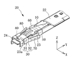
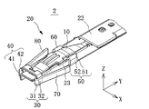
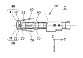
【解決手段】端子は、導電性接触板10と、導電性本体部20と、延出部30と、ランス70とを備える。導電性接触板10は、弾性を有し、相手方端子に接触する。導電性本体部20は、導電性接触板10を支持し、側板部23を有する。延出部30は、側板部23の+Z側の端から延出して導電性本体部20の外方に折り返されている折返し部分31と、折返し部分31の先端から延出して側板部23に重なっている重なり部分32とを有する。ランス70は、重なり部分32から突出し、片持ち梁状の部材である。
【選択図】図3
Description
弾性を有し、相手方端子に接触する導電性接触板と、
前記導電性接触板を支持し、第1壁部を有する筒状の導電性本体部と、
前記第1壁部の端から延出して前記導電性本体部の外方に折り返されている第1の折返し部分と、前記第1の折返し部分の先端から延出して前記第1壁部に重なっている第1の重なり部分と、を有する第1延出部と、
前記第1の重なり部分から突出する片持ち梁状の第1ランスと、
を備える。
前記導電性接触板は、前記第1壁部と前記第2壁部との間に配置されていてもよい。
前記第2の重なり部分から突出する片持ち梁状の第2ランスと、
を備えていてもよい。
前記第1の折返し部分は、前記導電性本体部の軸方向に直交する方向に平行な軸線を中心に折り返されていてもよい。
前記第1ランスを挟んだ、前記導電性本体部の他方の端部側に形成されている他端側の延出部を備え、
前記他端側の延出部は、前記第1壁部の端から延出して、前記導電性本体部の外方に折り返されている他端側の折返し部分と、前記他端側の折返し部分の先端から延出して前記第1壁部に重なっている他端側の重なり部分と、を有していてもよい。
本発明の第1の観点に係る端子と、
前記第1ランスに係合する係合部が形成されているハウジングと、
を備える。
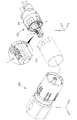
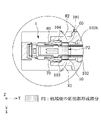
以下、本発明の実施の形態1に係る端子及びコネクタを、図1〜図8を参照して説明する。なお、理解を容易にするために、XYZ座標を設定し、適宜参照する。また、端子の導電性本体部の軸方向は、Y軸方向に平行な方向である。
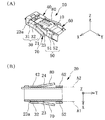
以下、本発明の実施の形態2に係る端子を、図10A、図10Bを参照して説明する。実施の形態1との相違点を主に説明する。説明した相違点以外は、実施の形態1と同じものとする。なお、理解を容易にするために、XYZ座標を設定し、適宜参照する。
以下、本発明の実施の形態3に係る端子を、図11A、図11Bを参照して説明する。実施の形態2との相違点を主に説明する。説明した相違点以外は、実施の形態2と同じものとする。なお、理解を容易にするために、XYZ座標を設定し、適宜参照する。
Claims (10)
- 弾性を有し、相手方端子に接触する導電性接触板と、
前記導電性接触板を支持し、第1壁部を有する筒状の導電性本体部と、
前記第1壁部の端から延出して前記導電性本体部の外方に折り返されている第1の折返し部分と、前記第1の折返し部分の先端から延出して前記第1壁部に重なっている第1の重なり部分と、を有する第1延出部と、
前記第1の重なり部分から突出する片持ち梁状の第1ランスと、
を備える、端子。 - 前記導電性本体部は、前記第1壁部に対向する第2壁部を有し、
前記導電性接触板は、前記第1壁部と前記第2壁部との間に配置されている、請求項1に記載の端子。 - 前記第2壁部の端から延出して前記導電性本体部の外方に折り返されている第2の折返し部分と、前記第2の折返し部分の先端から延出して前記第2壁部に重なっている第2の重なり部分と、を有する第2延出部と、
前記第2の重なり部分から突出する片持ち梁状の第2ランスと、
を備える請求項2に記載の端子。 - 前記導電性本体部には、前記第1壁部の外壁面から突出すると共に、前記第1の重なり部分に当接する突部が形成されている、請求項1から3のいずれか一項に記載の端子。
- 前記第1の折返し部分は、前記導電性本体部の軸方向に平行な軸線を中心に折り返されている、請求項1から4のいずれか一項に記載の端子。
- 前記第1の折返し部分は、前記導電性本体部の軸方向に直交する方向に平行な軸線を中心に折り返されている、請求項1から4のいずれか一項に記載の端子。
- 前記第1壁部は、前記導電性接触板に対面し、
前記第1の折返し部分は、前記導電性本体部の軸方向に直交する方向に平行な軸線を中心に折り返されている、請求項1に記載の端子。 - 前記第1ランスは、突出する方向に平行に形成されている折り目状の折り目部を有する、請求項1から7のいずれか一項に記載の端子。
- 前記第1延出部は、前記導電性本体部の一方の端部に形成され、
前記第1ランスを挟んだ、前記導電性本体部の他方の端部側に形成されている他端側の延出部を備え、
前記他端側の延出部は、前記第1壁部の端から延出して、前記導電性本体部の外方に折り返されている他端側の折返し部分と、前記他端側の折返し部分の先端から延出して前記第1壁部に重なっている他端側の重なり部分と、を有する、請求項1から8のいずれか一項に記載の端子。 - 請求項1から9のいずれか一項に記載の端子と、
前記第1ランスに係合する係合部が形成されているハウジングと、
を備える、コネクタ。
Priority Applications (5)
| Application Number | Priority Date | Filing Date | Title |
|---|---|---|---|
| JP2016089095A JP6341225B2 (ja) | 2016-04-27 | 2016-04-27 | 端子及びコネクタ |
| US15/489,365 US9905955B2 (en) | 2016-04-27 | 2017-04-17 | Terminal and connector |
| EP17167901.2A EP3240115B1 (en) | 2016-04-27 | 2017-04-25 | Terminal and connector |
| KR1020170053623A KR101911174B1 (ko) | 2016-04-27 | 2017-04-26 | 단자 및 커넥터 |
| CN201710287708.3A CN107425329B (zh) | 2016-04-27 | 2017-04-27 | 端子和连接器 |
Applications Claiming Priority (1)
| Application Number | Priority Date | Filing Date | Title |
|---|---|---|---|
| JP2016089095A JP6341225B2 (ja) | 2016-04-27 | 2016-04-27 | 端子及びコネクタ |
Publications (2)
| Publication Number | Publication Date |
|---|---|
| JP2017199541A true JP2017199541A (ja) | 2017-11-02 |
| JP6341225B2 JP6341225B2 (ja) | 2018-06-13 |
Family
ID=58632268
Family Applications (1)
| Application Number | Title | Priority Date | Filing Date |
|---|---|---|---|
| JP2016089095A Expired - Fee Related JP6341225B2 (ja) | 2016-04-27 | 2016-04-27 | 端子及びコネクタ |
Country Status (5)
| Country | Link |
|---|---|
| US (1) | US9905955B2 (ja) |
| EP (1) | EP3240115B1 (ja) |
| JP (1) | JP6341225B2 (ja) |
| KR (1) | KR101911174B1 (ja) |
| CN (1) | CN107425329B (ja) |
Families Citing this family (11)
| Publication number | Priority date | Publication date | Assignee | Title |
|---|---|---|---|---|
| US9905953B1 (en) | 2016-09-30 | 2018-02-27 | Slobodan Pavlovic | High power spring-actuated electrical connector |
| WO2018172406A1 (de) * | 2017-03-22 | 2018-09-27 | Hirschmann Automotive Gmbh | Kontaktelement für einen steckverbinder |
| CN107968268A (zh) * | 2018-01-04 | 2018-04-27 | 镇江市丹徒区飞翔电子有限公司 | 一种电子接插件 |
| JP6989715B2 (ja) | 2018-02-26 | 2022-01-05 | ロイヤル プレシジョン プロダクツ,エルエルシー | 高電力用途用のばね作動式電気コネクター |
| CN112956085B (zh) * | 2018-06-07 | 2023-09-15 | 皇家精密制品有限责任公司 | 具有内部弹簧部件的电连接器系统及其应用 |
| DE112020000459T5 (de) | 2019-01-21 | 2021-11-25 | Royal Precision Products, Llc | Stromverteilungsanordnung mit schraubenlosem sammelschienensystem |
| JP7134148B2 (ja) * | 2019-07-31 | 2022-09-09 | 株式会社鷺宮製作所 | 金属端子及び圧力スイッチ |
| US11043766B2 (en) * | 2019-08-29 | 2021-06-22 | J.S.T. Corporation | Electrical male terminal, and methods for connecting thereof |
| US11721942B2 (en) | 2019-09-09 | 2023-08-08 | Eaton Intelligent Power Limited | Connector system for a component in a power management system in a motor vehicle |
| JP2022547535A (ja) | 2019-09-09 | 2022-11-14 | ロイヤル プリシジョン プロダクツ エルエルシー | 読み取り可能かつ記録可能な印を有するコネクタ記録システム |
| KR20230042084A (ko) | 2020-07-29 | 2023-03-27 | 이턴 인텔리전트 파워 리미티드 | 원통형 단자 몸체를 갖는 전기 커넥터 시스템 |
Citations (7)
| Publication number | Priority date | Publication date | Assignee | Title |
|---|---|---|---|---|
| US3058091A (en) * | 1959-06-04 | 1962-10-09 | Amp Inc | Sheet metal pin socket |
| US4713026A (en) * | 1986-10-08 | 1987-12-15 | Interlock Corporation | Tab receptacle terminal having improved electrical and mechanical features |
| US4781628A (en) * | 1987-10-22 | 1988-11-01 | General Motors Corporation | Female electrical terminal |
| JPH06310218A (ja) * | 1993-04-28 | 1994-11-04 | Yazaki Corp | シールドコネクタ用端子およびシールドコネクタ |
| JP2002124335A (ja) * | 2000-10-18 | 2002-04-26 | Sumitomo Wiring Syst Ltd | 端子金具 |
| JP2004039534A (ja) * | 2002-07-05 | 2004-02-05 | Sumitomo Wiring Syst Ltd | コネクタ |
| WO2014045957A1 (ja) * | 2012-09-21 | 2014-03-27 | 矢崎総業株式会社 | コネクタ |
Family Cites Families (20)
| Publication number | Priority date | Publication date | Assignee | Title |
|---|---|---|---|---|
| US4209220A (en) * | 1978-06-05 | 1980-06-24 | General Motors Corporation | Wipe-in terminal for printed circuits |
| GB9301541D0 (en) * | 1993-01-27 | 1993-03-17 | Amp Gmbh | An electrical terminal with means to avoid locking lance damage and entanglement |
| JP3319292B2 (ja) * | 1996-07-26 | 2002-08-26 | 住友電装株式会社 | 雌側端子金具 |
| JP3225863B2 (ja) * | 1996-12-03 | 2001-11-05 | 住友電装株式会社 | 端子金具 |
| JPH10247543A (ja) | 1997-03-03 | 1998-09-14 | Sumitomo Wiring Syst Ltd | ターミナル |
| JP3494857B2 (ja) * | 1997-08-08 | 2004-02-09 | 矢崎総業株式会社 | 接続端子 |
| JP3656547B2 (ja) * | 2000-12-21 | 2005-06-08 | 住友電装株式会社 | 端子金具 |
| JP3745634B2 (ja) | 2001-03-15 | 2006-02-15 | 矢崎総業株式会社 | 端子金具 |
| JP4099219B2 (ja) * | 2003-04-15 | 2008-06-11 | 日本圧着端子製造株式会社 | 端子 |
| US6905376B2 (en) * | 2003-04-15 | 2005-06-14 | J.S.T. Mfg. Co., Ltd. | Terminal |
| JP4013151B2 (ja) * | 2004-04-13 | 2007-11-28 | 住友電装株式会社 | 雌端子金具 |
| US7175487B2 (en) | 2004-06-28 | 2007-02-13 | Delphi Technologies, Inc. | Electrical terminal element |
| US7537497B2 (en) * | 2005-09-26 | 2009-05-26 | Fci Americas Technology, Inc. | Multi-piece electrical receptacle terminal |
| US7371133B1 (en) * | 2007-01-18 | 2008-05-13 | Delphi Technologies, Inc. | Electrical socket terminal having a contact stabilizer |
| DE102007040937B3 (de) * | 2007-08-30 | 2009-01-15 | Tyco Electronics Amp Gmbh | Elektrischer Kontakt |
| JP4651129B2 (ja) * | 2008-12-26 | 2011-03-16 | 日本航空電子工業株式会社 | ソケットコンタクト及びコネクタ |
| DE102012209423A1 (de) | 2012-06-04 | 2013-12-05 | Robert Bosch Gmbh | Kontakt mit widerstandsfähiger Primärlanze zum Verriegeln in einer Kontaktkammer eines Steckverbinders |
| EP2690716B1 (de) * | 2012-07-24 | 2018-05-02 | Delphi Technologies, Inc. | Elektrisches Anschlusselement |
| EP2797173B8 (en) * | 2013-04-26 | 2019-01-09 | Aptiv Technologies Limited | Electrical terminal with a locking lance and manufacturing process thereof |
| DE102013223570B4 (de) * | 2013-11-19 | 2021-06-24 | Te Connectivity Germany Gmbh | Stiftkontakt mit einem als Stanzbiegeteil gefertigten Kontaktkörper und einem massiven Kontaktstift |
-
2016
- 2016-04-27 JP JP2016089095A patent/JP6341225B2/ja not_active Expired - Fee Related
-
2017
- 2017-04-17 US US15/489,365 patent/US9905955B2/en not_active Expired - Fee Related
- 2017-04-25 EP EP17167901.2A patent/EP3240115B1/en not_active Not-in-force
- 2017-04-26 KR KR1020170053623A patent/KR101911174B1/ko not_active Expired - Fee Related
- 2017-04-27 CN CN201710287708.3A patent/CN107425329B/zh not_active Expired - Fee Related
Patent Citations (7)
| Publication number | Priority date | Publication date | Assignee | Title |
|---|---|---|---|---|
| US3058091A (en) * | 1959-06-04 | 1962-10-09 | Amp Inc | Sheet metal pin socket |
| US4713026A (en) * | 1986-10-08 | 1987-12-15 | Interlock Corporation | Tab receptacle terminal having improved electrical and mechanical features |
| US4781628A (en) * | 1987-10-22 | 1988-11-01 | General Motors Corporation | Female electrical terminal |
| JPH06310218A (ja) * | 1993-04-28 | 1994-11-04 | Yazaki Corp | シールドコネクタ用端子およびシールドコネクタ |
| JP2002124335A (ja) * | 2000-10-18 | 2002-04-26 | Sumitomo Wiring Syst Ltd | 端子金具 |
| JP2004039534A (ja) * | 2002-07-05 | 2004-02-05 | Sumitomo Wiring Syst Ltd | コネクタ |
| WO2014045957A1 (ja) * | 2012-09-21 | 2014-03-27 | 矢崎総業株式会社 | コネクタ |
Also Published As
| Publication number | Publication date |
|---|---|
| EP3240115A1 (en) | 2017-11-01 |
| CN107425329B (zh) | 2019-05-28 |
| JP6341225B2 (ja) | 2018-06-13 |
| CN107425329A (zh) | 2017-12-01 |
| KR101911174B1 (ko) | 2018-12-19 |
| KR20170122672A (ko) | 2017-11-06 |
| EP3240115B1 (en) | 2019-01-09 |
| US20170317441A1 (en) | 2017-11-02 |
| US9905955B2 (en) | 2018-02-27 |
Similar Documents
| Publication | Publication Date | Title |
|---|---|---|
| JP6341225B2 (ja) | 端子及びコネクタ | |
| CN109804511B (zh) | 连接器结构 | |
| CN104137344B (zh) | 连接器、及在该连接器中使用的插头件和插口件 | |
| JP5001740B2 (ja) | 電気コネクタ | |
| CN112186418B (zh) | 连接器组件 | |
| JP5956071B2 (ja) | 接続端子 | |
| JPH11345645A (ja) | リセプタクル電気端子 | |
| CN113273037B (zh) | 连接器及外导体 | |
| CN111903006A (zh) | 连接器 | |
| CN104838543A (zh) | 阴端子 | |
| US10741974B2 (en) | Electrical connector | |
| CN104253345B (zh) | 连接器以及在该连接器中使用的插头件及插口件 | |
| CN113054450B (zh) | 端子模块、连接器以及嵌合结构 | |
| CN106025625A (zh) | 连接器和电连接装置 | |
| JP6486309B2 (ja) | コネクタ | |
| CN101471503B (zh) | 接触部件及电连接器 | |
| JP5201253B2 (ja) | コネクタ端子 | |
| JP2010157367A (ja) | 電気コネクタ | |
| US11018445B2 (en) | Terminal with electrically conductive tubular shaped body portion | |
| JP7640770B2 (ja) | コネクタセット及びコネクタ | |
| CN102437470B (zh) | 插座用屏蔽罩 | |
| JP7261044B2 (ja) | 雄端子 | |
| JP4551276B2 (ja) | ロック機構付きプラグ | |
| CN107069300A (zh) | 电连接器 | |
| JP2025162621A (ja) | 端子 |
Legal Events
| Date | Code | Title | Description |
|---|---|---|---|
| A977 | Report on retrieval |
Free format text: JAPANESE INTERMEDIATE CODE: A971007 Effective date: 20171027 |
|
| A131 | Notification of reasons for refusal |
Free format text: JAPANESE INTERMEDIATE CODE: A131 Effective date: 20171107 |
|
| A521 | Request for written amendment filed |
Free format text: JAPANESE INTERMEDIATE CODE: A523 Effective date: 20180104 |
|
| TRDD | Decision of grant or rejection written | ||
| A01 | Written decision to grant a patent or to grant a registration (utility model) |
Free format text: JAPANESE INTERMEDIATE CODE: A01 Effective date: 20180417 |
|
| A61 | First payment of annual fees (during grant procedure) |
Free format text: JAPANESE INTERMEDIATE CODE: A61 Effective date: 20180430 |
|
| R150 | Certificate of patent or registration of utility model |
Ref document number: 6341225 Country of ref document: JP Free format text: JAPANESE INTERMEDIATE CODE: R150 |
|
| R250 | Receipt of annual fees |
Free format text: JAPANESE INTERMEDIATE CODE: R250 |
|
| R250 | Receipt of annual fees |
Free format text: JAPANESE INTERMEDIATE CODE: R250 |
|
| LAPS | Cancellation because of no payment of annual fees |