JP2017199623A - スリーブ部材 - Google Patents
スリーブ部材 Download PDFInfo
- Publication number
- JP2017199623A JP2017199623A JP2016091290A JP2016091290A JP2017199623A JP 2017199623 A JP2017199623 A JP 2017199623A JP 2016091290 A JP2016091290 A JP 2016091290A JP 2016091290 A JP2016091290 A JP 2016091290A JP 2017199623 A JP2017199623 A JP 2017199623A
- Authority
- JP
- Japan
- Prior art keywords
- electric wire
- cylindrical portion
- cylindrical
- sleeve member
- slit
- Prior art date
- Legal status (The legal status is an assumption and is not a legal conclusion. Google has not performed a legal analysis and makes no representation as to the accuracy of the status listed.)
- Granted
Links
- 230000002093 peripheral effect Effects 0.000 claims abstract description 18
- 230000000149 penetrating effect Effects 0.000 claims abstract description 3
- 239000011162 core material Substances 0.000 description 20
- 230000006835 compression Effects 0.000 description 12
- 238000007906 compression Methods 0.000 description 12
- 238000000034 method Methods 0.000 description 10
- 238000012986 modification Methods 0.000 description 8
- 230000004048 modification Effects 0.000 description 8
- 238000003780 insertion Methods 0.000 description 5
- 230000037431 insertion Effects 0.000 description 5
- 238000005452 bending Methods 0.000 description 4
- 239000011247 coating layer Substances 0.000 description 4
- RYGMFSIKBFXOCR-UHFFFAOYSA-N Copper Chemical compound [Cu] RYGMFSIKBFXOCR-UHFFFAOYSA-N 0.000 description 2
- 230000001154 acute effect Effects 0.000 description 2
- 239000007769 metal material Substances 0.000 description 2
- 230000002265 prevention Effects 0.000 description 2
- 230000009466 transformation Effects 0.000 description 2
- 229910000838 Al alloy Inorganic materials 0.000 description 1
- 229910001369 Brass Inorganic materials 0.000 description 1
- 229910000881 Cu alloy Inorganic materials 0.000 description 1
- 238000013459 approach Methods 0.000 description 1
- 239000010951 brass Substances 0.000 description 1
- 150000001875 compounds Chemical class 0.000 description 1
- 239000000470 constituent Substances 0.000 description 1
- 238000000605 extraction Methods 0.000 description 1
- 239000002184 metal Substances 0.000 description 1
- 229910052751 metal Inorganic materials 0.000 description 1
- 238000005192 partition Methods 0.000 description 1
- 238000012545 processing Methods 0.000 description 1
- 238000007789 sealing Methods 0.000 description 1
- 238000006467 substitution reaction Methods 0.000 description 1
Images


Landscapes
- Connections Effected By Soldering, Adhesion, Or Permanent Deformation (AREA)
Abstract
Description
図1は、第1の実施形態に係るスリーブ部材の平面図である。図2は、図1のII−II’線に沿って切断し矢印方向から見たときの断面図である。図3は、図1のIII−III’線に沿って切断し矢印方向から見たときの断面図である。実施形態のスリーブ部材10は、2本の電線を突き合わせて電気的に接続するための部材であり、特に、無停電で作業を行う間接活線工法における電線の接続作業に用いることができる。
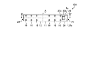
図9は、第2の実施形態に係るスリーブ部材の平面図である。図10は、図9のX−X’線に沿って切断し矢印方向から見たときの断面図である。なお、上述した実施形態と同様の構成については、同じ符号を付して説明を省略する場合がある。図9及び図10に示すように、本実施形態のスリーブ部材10Aは、2つの突出部24、24が設けられている。一方の突出部24は、中心軸AXの上方に設けられ、他方の突出部24は中心軸AXの下方に設けられる。このように突出部24、24を複数設けることにより、第1筒状部11に挿入された第1電線100と突出部24、24との接触箇所が増えるので、確実に第1電線100(図9、図10では図示を省略する)の仮固定を行うことができる。
図11は、第2の実施形態の変形例に係るスリーブ部材の平面図である。本変形例のスリーブ部材10Bにおいて、スリット部26Aは、中心軸AX方向に沿った方向に延びており、第1筒状部11の端部まで連続している。スリット部26Aの中心軸AX方向の位置は、突出部24、24と重なっている。
11 第1筒状部
12 第2筒状部
14 ストッパー
16 圧縮表示線
21 第1孔部
22 第2孔部
24 突出部
24a エッジ部
25、26 スリット部
25a 延出部
25b 屈曲部
25c エッジ部
31 隙間
100 第1電線
101 第2電線
104 圧縮工具
Claims (6)
- 内部空間に電線が挿入される筒状部と、
前記筒状部と一体に設けられ、前記筒状部の内周面から前記内部空間に突出し、前記筒状部に挿入された前記電線に接触して前記電線の抜け止めを行うための突出部と、
前記筒状部の内周面と外周面とを貫通し、前記筒状部の軸方向に沿った方向に長手を有するスリット部と、を有し、
前記突出部と前記スリット部とは、前記筒状部の前記電線が挿入される端部側に設けられ、かつ、前記筒状部の周方向において互いに間隔を有して設けられるスリーブ部材。 - 前記スリット部は、前記筒状部の端部まで連続して設けられる請求項1に記載のスリーブ部材。
- 前記スリット部は、前記筒状部の軸方向に沿った方向、又は前記筒状部の軸方向に対して傾いた方向に延びる延出部と、前記延出部の内壁から前記延出部の幅方向の外側に向かって屈曲する屈曲部とを含む請求項1又は請求項2に記載のスリーブ部材。
- 前記屈曲部は、前記突出部よりも前記筒状部の端部から離れた位置に設けられる請求項3に記載のスリーブ部材。
- 前記スリット部は、前記筒状部の周方向において間隔を有して複数設けられる請求項1から請求項4のいずれか1項に記載のスリーブ部材。
- 前記突出部は、前記筒状部に切り込みが設けられ、前記筒状部の一部が前記内部空間に折り曲げられて突出する請求項1から請求項5のいずれか1項に記載のスリーブ部材。
Priority Applications (1)
| Application Number | Priority Date | Filing Date | Title |
|---|---|---|---|
| JP2016091290A JP6740695B2 (ja) | 2016-04-28 | 2016-04-28 | スリーブ部材 |
Applications Claiming Priority (1)
| Application Number | Priority Date | Filing Date | Title |
|---|---|---|---|
| JP2016091290A JP6740695B2 (ja) | 2016-04-28 | 2016-04-28 | スリーブ部材 |
Publications (2)
| Publication Number | Publication Date |
|---|---|
| JP2017199623A true JP2017199623A (ja) | 2017-11-02 |
| JP6740695B2 JP6740695B2 (ja) | 2020-08-19 |
Family
ID=60238082
Family Applications (1)
| Application Number | Title | Priority Date | Filing Date |
|---|---|---|---|
| JP2016091290A Active JP6740695B2 (ja) | 2016-04-28 | 2016-04-28 | スリーブ部材 |
Country Status (1)
| Country | Link |
|---|---|
| JP (1) | JP6740695B2 (ja) |
Citations (7)
| Publication number | Priority date | Publication date | Assignee | Title |
|---|---|---|---|---|
| JPH03119960U (ja) * | 1990-03-20 | 1991-12-10 | ||
| US5863226A (en) * | 1995-12-28 | 1999-01-26 | Lan; Cheng Sun | Connector for coaxial cable |
| US6398593B1 (en) * | 2000-08-21 | 2002-06-04 | Ching-Shan Yeh | Conductive contact member for a cable connector |
| JP2010211988A (ja) * | 2009-03-09 | 2010-09-24 | Matsumura Seiki:Kk | 接続端子 |
| JP2011071043A (ja) * | 2009-09-28 | 2011-04-07 | Furukawa Denko Sangyo Densen Kk | 電線接続用具 |
| JP2011175769A (ja) * | 2010-02-23 | 2011-09-08 | Furukawa Denko Sangyo Densen Kk | 電線接続用具 |
| US8298020B1 (en) * | 2011-05-18 | 2012-10-30 | Ezconn Corporation | Central conductor of coaxial cable connector |
-
2016
- 2016-04-28 JP JP2016091290A patent/JP6740695B2/ja active Active
Patent Citations (7)
| Publication number | Priority date | Publication date | Assignee | Title |
|---|---|---|---|---|
| JPH03119960U (ja) * | 1990-03-20 | 1991-12-10 | ||
| US5863226A (en) * | 1995-12-28 | 1999-01-26 | Lan; Cheng Sun | Connector for coaxial cable |
| US6398593B1 (en) * | 2000-08-21 | 2002-06-04 | Ching-Shan Yeh | Conductive contact member for a cable connector |
| JP2010211988A (ja) * | 2009-03-09 | 2010-09-24 | Matsumura Seiki:Kk | 接続端子 |
| JP2011071043A (ja) * | 2009-09-28 | 2011-04-07 | Furukawa Denko Sangyo Densen Kk | 電線接続用具 |
| JP2011175769A (ja) * | 2010-02-23 | 2011-09-08 | Furukawa Denko Sangyo Densen Kk | 電線接続用具 |
| US8298020B1 (en) * | 2011-05-18 | 2012-10-30 | Ezconn Corporation | Central conductor of coaxial cable connector |
Also Published As
| Publication number | Publication date |
|---|---|
| JP6740695B2 (ja) | 2020-08-19 |
Similar Documents
| Publication | Publication Date | Title |
|---|---|---|
| CN103311686B (zh) | 带有压接端子的电线 | |
| KR200498486Y1 (ko) | 감소된 힘으로 수형 노즐의 삽입을 가능하게 하는 연결부의 암형 노즐 | |
| WO2016006516A1 (ja) | ワイヤ保護シースの接続構造、連結部材、ワイヤ保護シース構造体、及びワイヤ保護シースの接続方法 | |
| JP2010031939A (ja) | 電線固定部材 | |
| CN105659435A (zh) | 压接端子 | |
| JP2010086797A (ja) | 端子金具及び端子金具付き電線 | |
| JP6658443B2 (ja) | 導電路 | |
| JP2017199623A (ja) | スリーブ部材 | |
| JP6744089B2 (ja) | ガソリン直噴レール | |
| EP3079160A1 (en) | Coil end connecting structure | |
| JP2015156285A (ja) | 接続端子及びワイヤーハーネス | |
| WO2015019850A1 (ja) | アルミニウム電線の接続構造 | |
| JP2015158219A (ja) | 管継手 | |
| US20180131167A1 (en) | Single-core wire and wire harness | |
| JP5840867B2 (ja) | チューブ固定構造及びチューブ固定方法 | |
| JP2010193571A (ja) | ケーブル固定構造及び方法 | |
| JP2018174099A (ja) | 圧着端子用キャップ | |
| JP2016060450A (ja) | コラムチューブへのベアリングの固定方法 | |
| JP6593644B2 (ja) | 電線の接続構造およびワイヤハーネス | |
| US9437351B2 (en) | Shield wire for wiring harness and method of making the same | |
| JP7220909B2 (ja) | 雌型端子 | |
| CN109844300B (zh) | 端盖 | |
| JP6560695B2 (ja) | 接続方法 | |
| CN209415378U (zh) | 一种灯管灯头 | |
| JP6549795B2 (ja) | バネ組立体及びその製造方法 |
Legal Events
| Date | Code | Title | Description |
|---|---|---|---|
| A621 | Written request for application examination |
Free format text: JAPANESE INTERMEDIATE CODE: A621 Effective date: 20190411 |
|
| A977 | Report on retrieval |
Free format text: JAPANESE INTERMEDIATE CODE: A971007 Effective date: 20200115 |
|
| A131 | Notification of reasons for refusal |
Free format text: JAPANESE INTERMEDIATE CODE: A131 Effective date: 20200303 |
|
| A521 | Request for written amendment filed |
Free format text: JAPANESE INTERMEDIATE CODE: A523 Effective date: 20200413 |
|
| TRDD | Decision of grant or rejection written | ||
| A01 | Written decision to grant a patent or to grant a registration (utility model) |
Free format text: JAPANESE INTERMEDIATE CODE: A01 Effective date: 20200623 |
|
| A61 | First payment of annual fees (during grant procedure) |
Free format text: JAPANESE INTERMEDIATE CODE: A61 Effective date: 20200706 |
|
| R150 | Certificate of patent or registration of utility model |
Ref document number: 6740695 Country of ref document: JP Free format text: JAPANESE INTERMEDIATE CODE: R150 |