JP2017200344A - AC motor control device - Google Patents
AC motor control device Download PDFInfo
- Publication number
- JP2017200344A JP2017200344A JP2016090199A JP2016090199A JP2017200344A JP 2017200344 A JP2017200344 A JP 2017200344A JP 2016090199 A JP2016090199 A JP 2016090199A JP 2016090199 A JP2016090199 A JP 2016090199A JP 2017200344 A JP2017200344 A JP 2017200344A
- Authority
- JP
- Japan
- Prior art keywords
- division number
- calculation
- phase current
- change
- unit
- Prior art date
- Legal status (The legal status is an assumption and is not a legal conclusion. Google has not performed a legal analysis and makes no representation as to the accuracy of the status listed.)
- Granted
Links
Images



Landscapes
- Control Of Ac Motors In General (AREA)
Abstract
Description
本発明は、交流電動機の通電を制御する交流電動機の制御装置に関する。 The present invention relates to an AC motor control device that controls energization of an AC motor.
従来、電流センサが検出した相電流検出値に基づいてフィードバック制御を行う交流電動機の制御装置において、相電流の1次成分に重畳する高次成分の影響を低減する技術が知られている。
例えば特許文献1に開示された交流電動機の制御装置は、相電流検出値をフーリエ級数展開して1次成分を抽出し、抽出した1次電流に基づいてフィードバック制御を行う。このとき、電気角k周期を分割数Nで分割したサンプリング間隔でサンプリングされた相電流検出値に基づく算出値を積算することにより、フーリエ係数を演算する。
2. Description of the Related Art Conventionally, in an AC motor control device that performs feedback control based on a phase current detection value detected by a current sensor, a technique for reducing the influence of higher-order components superimposed on the primary component of phase current is known.
For example, the control device for an AC motor disclosed in
特許文献1には、交流電動機の回転数又は電気周波数によって、分割数Nを変更してもよいと記載されている。具体的には、回転数又は電気周波数が高くなるほど分割数Nを少なくすることにより、電気1周期の時間を分割数Nで分割した時間が処理時間を下回り、制御が破綻することを防止することができる。また、回転数又は電気周波数が低くなるほど分割数Nを多くすることにより、1次電流の検出精度を確保することができる。
ところで特許文献1の従来技術によるフーリエ係数の演算では、現在から遡って電気角k周期におけるN個の電気角及び相電流検出値を用いて積算値を算出する。したがって、分割数の変更時から電気角k周期の期間、変更前分割数による相電流検出値と、変更後分割数による相電流検出値との両方を用いたイレギュラーな演算が実行される。このとき、フーリエ級数展開による1次電流演算値が急変し、交流電動機のトルク変動やパワー変動が生じるおそれがある。
By the way, in the calculation of the Fourier coefficient according to the prior art of
本発明は、このような点に鑑みて創作されたものであり、その目的は、分割数を変更したとき、フーリエ級数展開による1次電流演算値が急変することを防止する交流電動機の制御装置を提供することにある。 The present invention was created in view of the above points, and an object of the present invention is to control an AC motor that prevents a sudden change in the primary current calculation value due to Fourier series expansion when the number of divisions is changed. Is to provide.
本発明の交流電動機の制御装置は、複数のスイッチング素子(21−26)の動作により直流電力を交流電力に変換し、交流電動機(80)に供給するインバータ(20)と、フィードバックされた相電流に基づいてインバータを操作し、交流電動機の通電を制御するインバータ制御部(30)とを備える。
本明細書で「交流電動機」は、交流駆動のモータ、発電機、及びモータジェネレータを含むものであり、例えば、ハイブリッド自動車や電気自動車の主機として用いられ駆動輪を駆動するためのトルクを発生するモータジェネレータが該当する。また、例えば、モータジェネレータの通電を制御する制御装置が「交流電動機の制御装置」に該当する。
The control apparatus for an AC motor of the present invention includes an inverter (20) that converts DC power into AC power by operation of a plurality of switching elements (21-26) and supplies the AC power to the AC motor (80), and a fed back phase current. And an inverter control unit (30) for controlling the energization of the AC motor.
In the present specification, the “AC motor” includes an AC drive motor, a generator, and a motor generator. For example, the AC motor is used as a main machine of a hybrid vehicle or an electric vehicle, and generates torque for driving drive wheels. Applicable to motor generators. Further, for example, a control device that controls energization of the motor generator corresponds to the “control device for an AC motor”.
本発明の第1の態様では、インバータ制御部は、サンプリング部(51)と、フーリエ係数演算部(53)と、分割数変更部(54)と、遡及推定部(55)とを有する。
サンプリング部は、電気角k周期(kは自然数)を「2以上の整数である分割数」で分割したサンプリング間隔で相電流検出値をサンプリングする。
フーリエ係数演算部は、相電流を電気角の関数として当該相の1次電流を抽出しフィードバックするフーリエ級数展開において、相電流検出値又は相電流推定値に基づく算出値を電気角k周期にわたって積算することによりフーリエ係数を演算する。
In the first aspect of the present invention, the inverter control unit includes a sampling unit (51), a Fourier coefficient calculation unit (53), a division number changing unit (54), and a retrospective estimation unit (55).
The sampling unit samples the phase current detection value at a sampling interval obtained by dividing the electrical angle k period (k is a natural number) by “a division number that is an integer of 2 or more”.
The Fourier coefficient calculation unit integrates the calculated value based on the detected phase current value or the estimated current value over the period of electrical angle k in the Fourier series expansion that extracts and feeds back the primary current of the phase as a function of the electrical current. To calculate the Fourier coefficient.
分割数変更部は、任意のタイミングで分割数を変更前分割数(N)から変更後分割数(M)に変更可能である。
分割数変更部により分割数が変更されたとき、フーリエ係数演算部が変更後分割数による演算に切り替える時点を演算切替時(tx)とする。遡及推定部は、フーリエ係数演算部が演算切替時から電気角k周期の期間に演算に用いる電気角及び相電流値として、変更前分割数を用いて算出されたフーリエ係数(asum、bsum)に基づき、変更後分割数に対応する電気角及び相電流推定値を演算切替時から遡って逆演算する。
The division number changing unit can change the division number from the pre-change division number (N) to the post-change division number (M) at an arbitrary timing.
When the division number is changed by the division number changing unit, the time point when the Fourier coefficient calculation unit switches to the calculation based on the changed division number is set as the calculation switching time (tx). The retrospective estimator uses the Fourier coefficients (a sum , b sum) calculated by using the division number before change as the electrical angle and the phase current value used for the calculation in the period of the electrical angle k from the time when the calculation is switched by the Fourier coefficient calculation unit. ), The electrical angle and the phase current estimated value corresponding to the post-change division number are calculated backwards from the time of calculation switching.
このように、フーリエ係数演算部は、演算切替時から電気角k周期の期間、変更前分割数による電気角及び相電流検出値を用いるのでなく、変更後分割数に対応する電気角及び相電流推定値を用いてフーリエ係数を演算する。これにより、変更後の分割数のみを用いた規則的な演算を実行することができる。したがって、分割数変更時にフーリエ級数展開による1次電流演算値が急変し、交流電動機のトルク変動やパワー変動が生じることを防止することができる。 As described above, the Fourier coefficient calculation unit does not use the electrical angle and phase current detection value based on the number of divisions before change, the period of electrical angle k from the time of calculation switching, but the electrical angle and phase current corresponding to the number of divisions after change. A Fourier coefficient is calculated using the estimated value. Thereby, a regular calculation using only the number of divisions after the change can be executed. Therefore, when the division number is changed, it is possible to prevent the primary current calculation value due to the Fourier series expansion from changing suddenly and causing torque fluctuation or power fluctuation of the AC motor.
本発明の第2の態様では、インバータ制御部は、複数のサンプリング部(51、52)と、フーリエ係数演算部(53)と、分割数変更部(54)とを有する。
複数のサンプリング部は、分割数の変更が通知された時から電気角k周期の期間である移行期間において、変更前分割数による相電流のサンプリングと、変更後分割数による相電流のサンプリングとを併行して実行する。
フーリエ係数演算部は、移行期間中は変更前分割数を用いてフーリエ係数を算出し、移行期間の終了時を演算切替時(tx)として変更後分割数による演算に切り替える。
この態様でも、分割数変更時における1次電流演算値の急変を防止することができる。
In the second aspect of the present invention, the inverter control unit includes a plurality of sampling units (51, 52), a Fourier coefficient calculation unit (53), and a division number changing unit (54).
The plurality of sampling units perform phase current sampling according to the number of divisions before change and phase current sampling according to the number of divisions after change in the transition period, which is a period of electrical angle k from when the change of the division number is notified. Run in parallel.
The Fourier coefficient calculation unit calculates the Fourier coefficient using the pre-change division number during the transition period, and switches the calculation to the calculation based on the post-change division number at the time of switching the calculation (tx).
Also in this aspect, it is possible to prevent a sudden change in the primary current calculation value when the division number is changed.
以下、交流電動機の制御装置の複数の実施形態を図面に基づいて説明する。複数の実施形態において実質的に同一の構成には、同一の符号を付して説明を省略する。また、以下の第1〜第3実施形態を包括して「本実施形態」という。
本実施形態の交流電動機の制御装置は、ハイブリッド自動車や電気自動車の動力源であるモータジェネレータ(以下「MG」)を駆動するシステムにおいて、三相交流モータであるMGの通電を制御する装置である。各実施形態の「MG」及び「MG制御装置」は、特許請求の範囲に記載の「交流電動機」及び「交流電動機の制御装置」に相当する。
Hereinafter, a plurality of embodiments of an AC motor control device will be described with reference to the drawings. In the plurality of embodiments, substantially the same configuration is denoted by the same reference numeral, and description thereof is omitted. The following first to third embodiments are collectively referred to as “this embodiment”.
The control apparatus for an AC motor according to this embodiment is an apparatus that controls energization of an MG that is a three-phase AC motor in a system that drives a motor generator (hereinafter referred to as “MG”) that is a power source of a hybrid vehicle or an electric vehicle. . “MG” and “MG control device” in each embodiment correspond to “AC motor” and “AC motor control device” recited in the claims.
[システム構成]
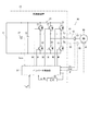
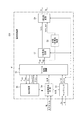
まず、各実施形態のMG制御装置が適用されるMG駆動システムの全体構成について図1を参照して説明する。図1には、一つのMGを備えるシステムを例示する。
MG駆動システム90は、充放電可能な二次電池であるバッテリ11の直流電力をインバータ20で三相交流電力に変換してMG80に供給するシステムである。MG駆動システム90においてMG制御装置10は、主にインバータ20及びインバータ制御部30を含む。なお、MG制御装置10は、二つ以上のMGを備えたMG駆動システムにも同様に適用可能である。
なお、MG制御装置10は、バッテリ11の電圧を昇圧してインバータ20に出力するコンバータを備えたMG駆動システムに適用されてもよい。また、MG制御装置10は、二つ以上のMGを備えたMG駆動システムにも同様に適用可能である。
[System configuration]
First, the overall configuration of an MG drive system to which the MG control device of each embodiment is applied will be described with reference to FIG. FIG. 1 illustrates a system including one MG.
The MG
The
MG80は、例えば永久磁石式同期型の三相交流モータである。本実施形態では、MG80は、ハイブリッド自動車の駆動輪を駆動するトルクを発生する電動機としての機能、及び、エンジンや駆動輪から伝達されるトルクを発電によってエネルギー回収する発電機としての機能を兼ね備える。
The
MG80の三相巻線81、82、83のうち少なくとも一相の巻線に接続される電流経路には、相電流を検出する電流センサが設けられる。図1に実線で示す代表的な実施形態では、V相巻線82に接続される電流経路に、V相電流Ivを検出する電流センサ87が設けられており、一相の電流としてV相電流Ivがインバータ制御部30に取得される。他の実施形態では、一相の電流としてU相電流Iu又はW相電流Iwがインバータ制御部30に取得されてもよい。また、図1に破線で示すように、V相電流Ivを検出する電流センサ87に加え、W相電流Iwを検出する電流センサ88がさらに設けられてもよい。或いは、三相の電流が検出されてもよい。
A current sensor for detecting a phase current is provided in a current path connected to at least one of the three-
検出する電流の相数に応じた演算処理の構成は、特許文献1(特許第5741966号公報)や後述の特許文献2(特許第5888567号公報)に開示された各実施形態を応用して適宜設計可能である。
MG80の電気角θは、例えばレゾルバ等の回転角センサ85により検出される。
The configuration of the arithmetic processing according to the number of phases of the current to be detected is appropriately determined by applying each embodiment disclosed in Patent Document 1 (Japanese Patent No. 5714966) and Patent Document 2 (Japanese Patent No. 5888567) described later. Design is possible.
The electrical angle θ of the
インバータ20は、上下アームの6つのスイッチング素子21−26がブリッジ接続されている。詳しくは、スイッチング素子21、22、23は、それぞれU相、V相、W相の上アームのスイッチング素子であり、スイッチング素子24、25、26は、それぞれU相、V相、W相の下アームのスイッチング素子である。スイッチング素子21−26は、例えばIGBTで構成され、低電位側から高電位側へ向かう電流を許容する還流ダイオードが並列に接続されている。
In the
インバータ20は、インバータ制御部30からのゲート信号UU、UL、VU、VL、WU、WLに従ってスイッチング素子21−26が動作することで直流電力を三相交流電力に変換する。そして、インバータ制御部30が演算した電圧指令に応じた相電圧Vu、Vv、VwをMG80の各相巻線81、82、83に印加する。平滑コンデンサ15は、インバータ20に入力されるシステム電圧Vsysを平滑化する。
電圧センサ27はシステム電圧Vsysを検出する。
The
インバータ制御部30は、マイコン等により構成され、図示しないCPU、ROM、I/O、及び、これらの構成を接続するバスライン等を内部に備えている。マイコンは、予め記憶されたプログラムをCPUで実行することによるソフトウェア処理や、専用の電子回路によるハードウェア処理による制御を実行する。
The
インバータ制御部30は、各センサが検出したシステム電圧Vsys、二相の相電流Iv、Iw、電気角θを取得する。また、インバータ制御部30は、微分器86により電気角θが時間微分された電気角速度ω[deg/s]を取得する。なお、インバータ制御部30の内部に微分器86を有してもよい。
電気角速度ωは、比例定数を乗じることにより、回転数Nr[rpm]に換算される。本明細書では「電気角速度ωを換算した回転数」を省略して、適宜「回転数ω」といい、「回転数ω」と「回転数Nr」とを併用する。特に「回転数Nr」は、後述の電流処理部にて分割数変更部が取得する情報として用いる。それ以外のモータ制御の説明では、主に「回転数ω」を用いる。
The
The electrical angular velocity ω is converted to a rotational speed Nr [rpm] by multiplying by a proportionality constant. In this specification, “the rotational speed converted from the electrical angular velocity ω” is omitted, and is appropriately referred to as “the rotational speed ω”, and “the rotational speed ω” and “the rotational speed Nr” are used together. In particular, “rotational speed Nr” is used as information acquired by the division number changing unit in a current processing unit described later. In other motor control descriptions, “rotational speed ω” is mainly used.
さらにインバータ制御部30は、上位制御回路からトルク指令Trq*が入力される。
インバータ制御部30は、これらの情報に基づいて、インバータ20を操作するゲート信号UU、UL、VU、VL、WU、WLを演算する。インバータ20は、ゲート信号UU、UL、VU、VL、WU、WLに従ってスイッチング素子21−26が動作することにより、バッテリ11から入力される直流電力を交流電力に変換しMG80に供給する。
Further, the
Based on such information, the
[インバータ制御部の構成]
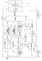
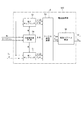
次に、インバータ制御部30の構成について、図2を参照して説明する。
インバータ制御部30は、一般的なフィードバック制御(図中、「FB制御」)の構成として、トルク推定部32、トルクフィードバック制御部340、電流指令演算部35、電流フィードバック制御部380、変調器60及びゲート信号生成部79を含む。本実施形態では、ベクトル制御により固定座標系を回転座標系に変換する機能は、電流処理部50に含まれる。また、インバータ制御部30は、特徴構成である電流処理部50を含む他、破線で示すように、スペクトル演算部40を含んでもよい。
[Configuration of inverter control unit]
Next, the configuration of the
The
まず、一般的なフィードバック制御の構成について説明する。本実施形態は、MG80の三相巻線81、82、83に流れる電流のうち少なくとも一相の電流がフィードバックされる構成において成立する。したがって、インバータ制御部30は、電流フィードバック制御部380のみを備え、トルクフィードバック制御部340を備えなくてもよい。或いは、図2に示すように、フィードバック電流に基づいてトルク推定値Trq_estを算出する構成のトルクフィードバック制御部340のみを備えてもよい。
First, a general feedback control configuration will be described. This embodiment is established in a configuration in which at least one phase of the current flowing through the three-
ただし、ハイブリッド自動車のMG駆動システム90に現実に適用される構成として、トルクフィードバック制御部340と電流フィードバック制御部380との両方を備える構成が一般的であるため、ここでは、その構成を代表的な実施形態として説明する。
この構成では、演算した電圧ベクトルの振幅Vrとシステム電圧Vsysとから算出される変調率に応じて、電圧ベクトルを演算するフィードバック方式が切り替えられる。すなわち、トルクフィードバック制御部340と電流フィードバック制御部380とが協働して電圧ベクトルを演算する場合と、電流フィードバック制御部380が単独で電圧ベクトルを演算する場合とがある。
However, since a configuration including both the torque
In this configuration, the feedback method for calculating the voltage vector is switched according to the modulation factor calculated from the calculated amplitude Vr of the voltage vector and the system voltage Vsys. That is, there are a case where the torque
トルクフィードバック制御部340は、トルク減算器33及び制御器34を有する。
電流フィードバック制御部380は、電流減算器36、制御器37、制御器38、電圧振幅/位相演算部39を有する。このうち、制御器37と、制御器38及び電圧振幅/位相演算部39とは、上述の二つのフィードバック方式に応じて選択的に設けられる。
The torque
The current
最初に、両方のフィードバック方式に共通の構成を説明する。
電流処理部50は、相電流検出値に基づき算出したdq軸電流Id、Iqを電流減算器36にフィードバックする。
電流指令演算部35は、トルク指令Trq*に基づき、例えば電流当たり最大トルクが得られるように、マップや数式を用いてdq軸電流指令Id*、Iq*を演算する。
電流フィードバック制御部380の電流減算器36は、dq軸電流指令Id*、Iq*と、電流処理部50からフィードバックされるdq軸電流Id、Iqとの電流偏差ΔId、ΔIqを算出する。
First, a configuration common to both feedback systems will be described.
The
Based on the torque command Trq * , the current command calculation unit 35 calculates dq-axis current commands Id * and Iq * using a map or a mathematical formula so that, for example, the maximum torque per current can be obtained.
The
続いて、トルクフィードバック制御部340と電流フィードバック制御部380とが協働して電圧ベクトルを演算する場合の構成を説明する。
トルク推定部32は、dq軸電流Id、Iq、及び、MG80のモータ定数に基づき、トルク推定値Trq_estを算出する。
Next, a configuration when the torque
The
トルクフィードバック制御部340のトルク減算器33は、トルク指令Trq*とトルク推定値Trq_estとのトルク偏差ΔTrqを算出する。制御器34は、トルク偏差ΔTrqを0に収束させるように、PI演算により電圧位相φを演算し、変調器60に出力する。
また、電流フィードバック制御部380の制御器37は、電流偏差ΔId、ΔIqを0に収束させるように、PI演算により電圧振幅Vrを演算し、変調器60に出力する。
The torque subtractor 33 of the torque
Further, the
次に、電流フィードバック制御部380が単独で電圧ベクトルを演算する場合の構成を説明する。
電流フィードバック制御部380の制御器38は、電流偏差ΔId、ΔIqを0に収束させるように、PI演算によりdq軸電圧指令Vd*、Vq*を演算する。電圧振幅/位相演算部39は、dq軸電圧指令Vd*、Vq*を電圧振幅Vr及び電圧位相φに変換し、変調器60に出力する。なお、図2には、電圧位相φをd軸基準で定義する例を参考に示しているが、q軸基準で電圧位相を定義してもよい。
Next, a configuration when the current
The
こうして変調器60は、いずれかのフィードバック方式で演算された電圧振幅Vr及び電圧位相φが入力される。また、変調器60は、システム電圧Vsys、電気角θ、回転数ω等の情報が入力される。変調器60は、これらの情報に基づき、インバータ20を操作する電圧信号をゲート信号生成部79に出力する。
変調器60は、電圧信号として、例えば予め記憶された複数のパルスパターンの中から適当なパターン信号を選択する。或いは、相電圧と搬送波との比較により、PWM信号を生成する。また、変調率等に応じて、これらの信号を切り替えてもよい。
ゲート信号生成部79は、変調器60が出力したパルスパターン又はPWM信号に基づいて、ゲート信号UU、UL、VU、VL、WU、WLを生成し、インバータ20のスイッチング素子21−26に出力する。
Thus, the
The
The gate
スペクトル演算部40は、MG80に流れる一相以上の相電流のスペクトルを検出又は推定する。例えば、スペクトル演算部40は、V相電流Ivを取得し、高速フーリエ変換(FFT)等の手段によって当該相電流のスペクトルを検出してもよく、或いは、変調器60が出力する電圧信号に基づいてスペクトルを推定してもよい。
The
[電流処理部の構成、作用]
次に、電流処理部50の構成、作用について説明する。電流処理部50には、電流センサ87が検出したV相電流Ivに加え、電気角θ及び回転数Nrが入力される。
ところで、従来技術である特許文献1に記載されている通り、MG制御装置では、フィードバックされる相電流に高次成分が重畳したり、相電流がオフセットしたりする場合がある。そこで、相電流検出値をフーリエ級数展開して抽出した1次電流演算値を用いてフィードバック制御することで、高次成分による騒音を低減し、相電流のオフセットによるトルク変動やパワー変動を抑制可能となる。
[Configuration and operation of current processing unit]
Next, the configuration and operation of the
By the way, as described in
本実施形態の電流処理部50の主要な機能は、特許文献1に開示された「1次電流演算部」及び「2相3相変換部」を合わせたものに相当する。すなわち、電流処理部50は、電流センサ87が検出した相電流検出値をフーリエ級数展開して1次成分を抽出し、さらに、相電流の1次成分をdq軸電流に変換してフィードバックする機能を備える。
特許文献1の従来技術では、このフーリエ級数展開において、電気角k周期を分割数Nで分割したサンプリング間隔でサンプリングした相電流検出値を電気角k周期にわたって積算することによりフーリエ係数を演算する。なお、特許文献1では、「電気角k周期を分割数Nで分割したサンプリング間隔」を「積算角の間隔」と表している。積算角の考え方やフーリエ係数の演算式、及び、フーリエ係数を用いた1次電流の演算式等については特許文献1の開示内容に準ずるものとし、本明細書では詳細な説明を省略する。
The main function of the
In the prior art of
従来技術の第2実施形態では、積算角の間隔は、電気角k周期を分割数Nで等分割した一定間隔Δに設定される。この構成において、フーリエ係数a1、b1、及び例えばV相の1次電流Iv1sは、式(1.1)〜(1.3)により算出される。式(1.2)、(1.3)は、積算期間における積算演算を表している。
以下の式で変数「n」はサンプリング値について用いる。また、式中のフーリエ係数の記号「エー」について、明細書及び一部の図面では便宜上「a」の字体で代替する。
In the second embodiment of the prior art, the interval between the integrated angles is set to a constant interval Δ obtained by equally dividing the electrical angle k cycle by the division number N. In this configuration, the Fourier coefficients a1 and b1 and, for example, the V-phase primary current Iv1s are calculated by equations (1.1) to (1.3). Expressions (1.2) and (1.3) represent integration calculations during the integration period.
In the following equation, the variable “n” is used for the sampling value. In addition, the symbol “A” of the Fourier coefficient in the equation is replaced with the letter “a” for convenience in the specification and some drawings.

また、特許文献1の段落[0084]には、次のように記載されている。
「分割数Nを固定した場合、回転数Nrに応じて積算タイミングの周期が変動する。そこで、積算の精度を適正に確保できるよう、交流電動機の回転数Nr、又は電気周波数によって、分割数Nを変更してもよい。具体的には、回転数Nr又は電気周波数が高くなるほど分割数Nを少なくし、回転数Nr又は電気周波数が低くなるほど分割数Nを多くするとよい。」
Further, paragraph [0084] of
“When the number of divisions N is fixed, the period of integration timing varies according to the number of rotations Nr. Therefore, the number of divisions N depends on the number of rotations Nr of the AC motor or the electrical frequency so that the accuracy of integration can be appropriately secured. Specifically, the division number N may be decreased as the rotational speed Nr or the electrical frequency is increased, and the division number N may be increased as the rotational speed Nr or the electrical frequency is decreased.
特許文献1には、分割数を変更した直後、詳しくは、フーリエ係数演算に用いる分割数を切り替えてから電気角k周期の期間における積算演算について何ら記載されていない。しかし、分割数変更時の演算において次に説明するような問題が発生する可能性がある。この問題について、図3〜図6を参照し、二通りの積算手法を想定して説明する。
ここでは、積算期間の周期を「k=1」として説明する。また、「k=1」の場合の積算期間を「電気1周期」と記載する。
In
Here, the period of the integration period is described as “k = 1”. In addition, the integration period in the case of “k = 1” is described as “1 electrical cycle”.
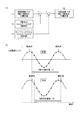
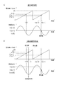
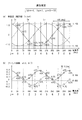
図3に示す第1の積算手法は、前回の電気1周期分の積算値から最も古い値を減算すると共に、最新の値を加算することにより今回の積算値を算出する手法である。図3(a)には制御ブロックを示し、図3(b)には電気角θの関数であるV相電流Iv(θ)の時間変化を示す。
<1>は「前回演算でのN個(すなわち1周期分)の積算値」である。<2>の「現在からN個前のIvcosθ及びIvsinθ」は、図3(b)の「廃棄値」に相当する。同様に、<3>の「サンプリングされたIvcosθ及びIvsinθ」は、「現在値」に相当する。<4>は、「今回演算でのN個(すなわち1周期分)の積算値」である。
<1>から<2>が減算され、<3>が加算されることにより、<4>が算出される。
The first integration method shown in FIG. 3 is a method for calculating the current integrated value by subtracting the oldest value from the integrated value for the previous electrical cycle and adding the latest value. FIG. 3A shows a control block, and FIG. 3B shows a time change of the V-phase current Iv (θ) as a function of the electrical angle θ.
<1> is “the integrated value of N (that is, one period) in the previous calculation”. <N> “Nv previous Ivcos θ and Ivsin θ” corresponds to the “discard value” in FIG. Similarly, “sampled Ivcos θ and Ivsin θ” in <3> corresponds to “current value”. <4> is “N integrated values (that is, one cycle) in the current calculation”.
<4> is calculated by subtracting <2> from <1> and adding <3>.
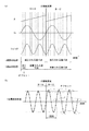
図4に、第1の積算手法において分割数をN(例えば16)からM(例えば12)に変更した場合の様子を示す。ここで、「Ivsinθ」は、フーリエ係数演算において積算される「Ivcosθ」及び「Ivsinθ」を代表して示すものである。
分割数の変更タイミングと演算タイミングとが一致すると仮定すると、分割数を変更した瞬間に算出されるフーリエ係数a1は、式(2)に示す通り、同じ値となる。
Assuming that the change timing of the number of divisions coincides with the calculation timing, the Fourier coefficient a1 calculated at the moment when the number of divisions is changed has the same value as shown in Expression (2).
その後の電気1周期の期間において、演算したい1次電流値は、本来、分割数とは関係ないため、分割数変更前後の積算値a1、b1は、同じ値でなければならない。そこで、図4(a)に示すように、分割数変更前の16点の値が減算され、分割数変更後の12点の値が加算される処理が理想である。しかし現実の処理では、分割数変更前の16点の値のうち、分割数変更後に加算される12点に対応する12点のみが減算され、4点の値が残ることとなる。
このように、加算する値の数と減算する値の数との違いにより、図4(b)に示すように、分割数変更後の1次電流演算値にオフセットが発生し、振幅が増大する。
In the subsequent period of one electrical cycle, the primary current value to be calculated is essentially unrelated to the number of divisions, so the integrated values a1 and b1 before and after the division number change must be the same value. Therefore, as shown in FIG. 4A, the process of subtracting the 16 points before changing the number of divisions and adding the 12 points after changing the number of divisions is ideal. However, in actual processing, only the 12 points corresponding to the 12 points added after the division number change are subtracted from the 16 point values before the division number change, and the four point values remain.
Thus, due to the difference between the number of values to be added and the number of values to be subtracted, as shown in FIG. 4B, an offset occurs in the primary current calculation value after changing the division number, and the amplitude increases. .
次に、図5に示す第2の積算手法では、N回前のサンプリング時t[n−N]から今回のサンプリング時t[n−1]まで、電気角θ[n−N]・・・θ[n−1]にサンプリングしたN個の相電流検出値Iv[n−N]・・・Iv[n−1]をホールドしておく。そして、毎回の演算時において、現在から遡って各N個のIvcosθ、Ivsinθの値を積算してフーリエ係数a1、b1を算出する。 Next, in the second integration method shown in FIG. 5, the electrical angle θ [n−N]... From the sampling time t [n−N] N times before to the current sampling time t [n−1]. N phase current detection values Iv [n−N]... Iv [n−1] sampled in θ [n−1] are held. Then, at the time of each calculation, the Fourier coefficients a1 and b1 are calculated by integrating the values of N Ivcos θ and Ivsin θ retroactively from the present.
図6に、第2の積算手法において分割数をN(例えば16)からM(例えば8)に変更した場合の様子を示す。図6(a)に示すように、この手法では、分割数が変更されてから電気1周期の期間、変更後分割数M個の積算周期が電気1周期ではなくなる。
これにより、図4(b)に示すように、分割数変更後の電気1周期の期間において1次電流演算値に変動が発生する。
FIG. 6 shows a state where the number of divisions is changed from N (for example, 16) to M (for example, 8) in the second integration method. As shown in FIG. 6A, in this method, the period of one electrical cycle after the division number is changed, and the integration period of the changed division number M is not one electrical cycle.
As a result, as shown in FIG. 4B, the primary current calculation value fluctuates in the period of one electrical cycle after changing the number of divisions.
以上のように、フーリエ係数の演算における従来の積算手法では、分割数の変更時から電気1周期の期間は、変更前分割数Nによる相電流検出値と、変更後分割数Mによる相電流検出値との両方を用いたイレギュラーな演算が実行される。このとき、フーリエ級数展開による1次電流演算値Iv1sが急変し、MG80のトルク変動やパワー変動が生じるおそれがある。
そこで本実施形態は、分割数を変更したとき、フーリエ級数展開による1次電流演算値が急変することを防止するための電流処理部の構成及び作用に特徴を有する。
As described above, in the conventional integration method in the calculation of the Fourier coefficient, the phase current detection value based on the division number N before the change and the phase current detection based on the division number M after the change are performed during the period of one electrical cycle from the change of the division number. Irregular operations using both values are performed. At this time, the primary current calculation value Iv1s due to Fourier series expansion may change suddenly, and torque fluctuation and power fluctuation of the
Therefore, this embodiment is characterized by the configuration and operation of the current processing unit for preventing the primary current calculation value due to Fourier series expansion from changing suddenly when the division number is changed.
以下、電流処理部50の詳細構成について実施形態毎に説明する。各実施形態の電流処理部の符号として、それぞれ「50」に続く3桁目に実施形態の番号を付して区別する。
(第1実施形態)
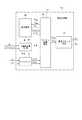
図7に示すように、第1実施形態の電流処理部501は、サンプリング部51、フーリエ係数演算部53、分割数変更部54、遡及推定部55及び電流ベクトル演算部56を有する。
Hereinafter, the detailed configuration of the
(First embodiment)
As illustrated in FIG. 7, the
フーリエ級数展開の積算期間を一般化して表すと、サンプリング部51は、電気角k周期(kは自然数)を「2以上の整数である分割数」で分割したサンプリング間隔で相電流検出値をサンプリングする。また、フーリエ係数演算部53は、「相電流を電気角の関数として当該相の1次電流を抽出しフィードバックするフーリエ級数展開」において、相電流検出値又は相電流推定値に基づく算出値を電気角k周期にわたって積算することによりフーリエ係数を演算する。
When the integration period of the Fourier series expansion is generalized, the
ただし、第1〜第3実施形態では、積算期間の周期を「k=1」とし、「k=1」の場合の積算期間を「電気1周期」と記載する。また、第1〜第3実施形態では、一相の電流センサ87が検出したV相電流Ivがサンプリング部51に入力されるものとする。
したがって、第1〜第3実施形態のサンプリング部51は、電気角θ及びV相電流Ivを取得し、電気1周期を「2以上の整数である分割数」で分割したサンプリング間隔で、すなわち電気角θ[n]毎に相電流検出値Iv[n]をサンプリングする。
However, in the first to third embodiments, the period of the integration period is “k = 1”, and the integration period in the case of “k = 1” is described as “one electrical period”. In the first to third embodiments, the V-phase current Iv detected by the one-phase
Therefore, the
以下、分割数の記号は原則として「N」を用い、分割数の変更について言及するとき、変更前分割数を「N」、変更後分割数を「M」として区別する。また、図9、図10及び数式では、分割数を一般的に表す変数として「p」を用いる。
なお、分割数は、概念上「2以上の整数」と定義しているが、実用上の分割数は3以上に設定されることが好ましい。
Hereinafter, “N” is used as the symbol for the number of divisions, and when referring to the change of the number of divisions, the number of divisions before change is distinguished as “N” and the number of divisions after change is distinguished as “M”. In FIG. 9, FIG. 10, and the mathematical formula, “p” is used as a variable that generally represents the number of divisions.
The number of divisions is conceptually defined as “an integer of 2 or more”, but the number of practical divisions is preferably set to 3 or more.
分割数変更部54は、MG80の回転数Nrやスペクトル等に応じて、任意のタイミングで分割数を変更可能である。分割数変更部54は、例えば特許文献1の知見に従い、回転数Nrが高くなるほど分割数を少なくし、回転数Nrが低くなるほど分割数を多くするように変更してもよい。また、分割数変更部54は、特定周波数の相電流スペクトルの振幅が所定の閾値以上であるとき、特定の分割数の使用を禁止してもよい。例えば、相電流11次又は13次成分のスペクトルの振幅が閾値以上であるとき、分割数として「12」の使用を禁止すること等が考えられる。
分割数変更部54は、変更前分割数Nから変更後分割数Mへの変更を決定すると、変更前後の分割数N、Mをサンプリング部51及びフーリエ係数演算部53に通知し、また、変更後分割数Mを遡及推定部55に通知する。
The division
When the division
遡及推定部55は、第1、第2実施形態における最も特徴的な構成である。
以下、「分割数変更部54により分割数が変更されたとき、フーリエ係数演算部53が変更後分割数Mによる演算に切り替える時点」を「演算切替時tx」とする。第1、第2実施形態では、制御の遅延時間を無視し、分割数の変更時と演算切替時txとがほぼ同時であると仮定する。
遡及推定部55は、フーリエ係数演算部53が演算切替時txから電気1周期の積算期間に演算に用いる電気角及び相電流値として、変更後分割数Mに対応する電気角及び相電流推定値を演算切替時txから遡って推定演算する。
このとき遡及推定部55は、フーリエ係数演算部53から、演算切替時の電気角θx、及び「変更前分割数Nを用いて算出されたフーリエ係数asum、bsum」を取得し、これに基づく「逆演算」を行う。この逆演算の詳細については後述する。
The
Hereinafter, “when the division number is changed by the division
The
At this time, the
フーリエ係数演算部53は、常時、サンプリング部51から電気角θ[n]及び相電流検出値Iv[n]を取得する。また、分割数が変更されたとき、演算切替時txから電気1周期の期間、遡及推定部55から電気角θ[j]及び相電流推定値Ivest[j]を取得する。以下、変数「j」は推定値について用いる。
このように、相電流検出値Iv[n]又は推定値Ivest[j]と、それに対応する電気角θ[n]、θ[j]とは1セットの情報である。ただし、これらを常に併記すると冗長になるため、以下の明細書中の記載では、主に相電流検出値Iv[n]又は推定値Ivest[j]について言及し、対応する電気角θ[n]、θ[j]については適宜記載を省略する。例えば、相電流検出値Iv[n]又は推定値Ivest[j]を取得したとき、対応する電気角の情報を同時に取得することは自明であると解釈する。
The Fourier
Thus, the phase current detection value Iv [n] or the estimated value Ivest [j] and the corresponding electrical angles θ [n], θ [j] are a set of information. However, since it becomes redundant if they are always written together, the description in the following specification mainly refers to the phase current detection value Iv [n] or the estimated value Ivest [j], and the corresponding electrical angle θ [n]. , Θ [j] are omitted as appropriate. For example, when the phase current detection value Iv [n] or the estimated value Ivest [j] is acquired, it is obvious that the corresponding electrical angle information is acquired at the same time.
分割数が変更されないとき、フーリエ係数演算部53は、サンプリング部51から取得した相電流検出値Iv[n]に基づく算出値を電気1周期にわたって積算することによりフーリエ係数asum、bsumを演算する。
一方、分割数が変更されたとき、フーリエ係数演算部53は、サンプリング部51から取得した相電流検出値Iv[n]に基づく算出値、及び、遡及推定部55から取得した相電流推定値Ivest[j]に基づく算出値を電気1周期にわたって積算することによりフーリエ係数asum、bsumを演算する。
ここで、「相電流検出値又は推定値に基づく算出値」とは、図10等におけるフーリエ係数の要素a[n]、b[n]又はa[j]、b[j]を意味する。
When the number of divisions is not changed, the Fourier
On the other hand, when the division number is changed, the Fourier
Here, the “calculated value based on the detected phase current value or the estimated value” means the elements a [n], b [n] or a [j], b [j] of the Fourier coefficient in FIG.
電流ベクトル演算部56は、フーリエ係数演算部53が演算したフーリエ係数asum、bsumに基づいて、V相電流の1次成分を演算することなく、dq軸電流Id、Iqを直接演算する。
この電流ベクトル演算部56の構成は、特許第5888567号公報に開示されたものと同じである。以下、この特許第5888567号公報を「特許文献2」と称する。特許文献2は、本発明全体の課題に関連するものでないため「背景技術」の欄には記載せず、主に第1実施形態の説明で引用する。
Based on the Fourier coefficients a sum and b sum calculated by the Fourier
The configuration of the current
特許文献2の段落[0064]には、V相電流から算出されたフーリエ係数に基づいてdq軸電流Id、Iqを算出する計算式が開示されている。第1実施形態の電流ベクトル演算部56は、この計算式を用いてdq軸電流Id、Iqを算出する。つまり、第1実施形態では、「相電流の1次成分を座標変換したdq軸電流演算値」が「発明が解決しようとする課題」に記載された「フーリエ級数展開による1次電流演算値」に相当する。
なお、V相電流に代えてU相電流又はW相電流から算出されたフーリエ係数に基づいてdq軸電流Id、Iqを算出する構成でも、特許文献2の対応する計算式を同様に用いることができる。
Paragraph [0064] of
It should be noted that, even in a configuration in which the dq-axis currents Id and Iq are calculated based on the Fourier coefficient calculated from the U-phase current or the W-phase current instead of the V-phase current, the corresponding calculation formula in
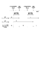
第1実施形態によるフーリエ係数演算の積算手法について、図8を参照する。図8は、上述の二通りの積算手法による課題を示す図4、図6に対応する。
例えば、分割数が「N=16」から「M=8」に変更されたとき、フーリエ係数演算部53は、演算切替時tx後のフーリエ係数演算において、変更前分割数Nによるサンプリングで得られた検出値を使用しない。その代わり、分割数変更前の電気1周期分の過去値として、「変更前分割数Nを用いて算出されたフーリエ係数asum、bsum」に基づいて遡及推定部55が推定した「変更後分割数Mに対応する推定値」を用いる。
FIG. 8 is referred to for the integration method of the Fourier coefficient calculation according to the first embodiment. FIG. 8 corresponds to FIG. 4 and FIG. 6 showing the problems caused by the above-described two integration methods.
For example, when the number of divisions is changed from “N = 16” to “M = 8”, the Fourier
要するに、遡及推定部55は、「分割数変更前の推定値」と「分割数変更後の検出値」とを電気1周期にわたって積算する。図8では、推定値を四角印で示し、検出値を丸印で示す。また、現在が時刻t4である場合の値を実線で記す。破線四角の推定値は、演算切替時tx以後の時刻t0〜t3で用いられた推定値を示す。
ここで、遡及推定部55は、「変更前分割数Nを用いて算出されたフーリエ係数asum、bsum」として、演算切替時txの直前に算出された値を用いることが好ましい。この「直前」には、実質的な「同時」が含まれる。
In short, the
Here, the
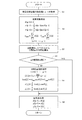
次に、図9、図10を参照し、第1実施形態によるフーリエ係数演算処理を説明する。図9のフローチャートには、フーリエ係数演算処理のルーチンを示す。以下のフローチャートの説明で、記号「S」はステップを意味する。フローチャートのS2及びS5では、それぞれ図10(a)、(b)のタイムチャートを参照する。 Next, a Fourier coefficient calculation process according to the first embodiment will be described with reference to FIGS. 9 and 10. The flowchart of FIG. 9 shows a routine for Fourier coefficient calculation processing. In the description of the flowchart below, the symbol “S” means a step. In S2 and S5 of the flowchart, the time charts of FIGS. 10A and 10B are referred to, respectively.
S1で、フーリエ係数演算部53は、サンプリング部51が新たにサンプリングした相電流検出値Iv[p−1]を現在値として取得する。現在から遡って電気1周期の期間において、前回までの相電流検出値Iv[0],・・・,Iv[p−2]は、前回までのルーチンで取得されている。ここで、pは分割数を示す。
S2では、式(3.1)〜(3.5)による通常演算処理が実行される。以下の式で、電気角θの単位は[deg]とする。
In S1, the Fourier
In S2, normal calculation processing according to equations (3.1) to (3.5) is executed. In the following formula, the unit of the electrical angle θ is [deg].
まず式(3.1)により、電気角θの現在値をθ[p−1]とする。
以下、式(3.4)、(3.5)において積算されるa[n]、b[n]を「フーリエ係数の要素」という。フーリエ係数演算部53は、式(3.2)、(3.3)により、現在値の電気角θ[p−1]及び相電流検出値Iv[p−1]に基づき、要素a[p−1]、b[p−1]を算出する。そして、フーリエ係数演算部53は、式(3.4)、(3.5)により、前回までのルーチンで算出済の要素を含めたp個の要素a[n]、b[n]を積算し、フーリエ係数asum、bsumを算出する。
First, the current value of the electrical angle θ is θ [p−1] according to the equation (3.1).
Hereinafter, a [n] and b [n] integrated in equations (3.4) and (3.5) are referred to as “elements of Fourier coefficients”. The Fourier
S3で、分割数変更部54は、MG80の回転数や相電流スペクトルに基づいて分割数pの今回値を算出する。
S4では分割数pが前回値と同じであるか判定する。S4でYESの場合、S6に移行し、NOの場合、S5の分割数変更時処理に移行する。
S5では、式(4.1)〜(4.4)による分割数変更時処理が実行される。変更後の分割数pについて、変数jは「j=0,・・・,p−1」のp個の値を取る。
In S3, the division
In S4, it is determined whether the division number p is the same as the previous value. If YES in S4, the process proceeds to S6. If NO, the process proceeds to the process for changing the number of divisions in S5.
In S5, the process for changing the number of divisions according to equations (4.1) to (4.4) is executed. With respect to the changed division number p, the variable j takes p values of “j = 0,.
遡及推定部55は、演算切替時txの電気角θxを基準として、式(4.1)により、変更後分割数pに対応する電気角θ[j]を算出する。
また、遡及推定部55は、S2で算出されたフーリエ係数asum、bsumを用いて、式(4.2)により、変更後分割数pに対応する相電流推定値Ivest[j]を逆演算する。
The
Further, the
フーリエ係数演算部53は、式(4.3)、(4.4)により、電気角θ[j]及び相電流推定値Ivest[j]を用いてフーリエ係数の要素a[j]、b[j]を算出する。
図10(b)に示すように、分割数変更後のデータは、電気角θ[p−2],θ[p−1]及び相電流検出値Iv[p−2],Iv[p−1]等が用いられる。また、分割数変更前のデータは、電気角θ[0]及び相電流推定値Ivest[0]等が用いられる。
The Fourier
As shown in FIG. 10B, the data after changing the division number includes the electrical angles θ [p−2] and θ [p−1] and the phase current detection values Iv [p−2] and Iv [p−1]. ] Etc. are used. In addition, the electrical angle θ [0], the phase current estimated value Ivest [0], and the like are used as data before the division number change.
S6は、値更新処理のステップである。式(5.1)〜(5.3)に示すように、今回処理での「n」番目の値は、次回処理での「n−1」番目の値として更新される。
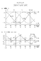
次に図11、図12を参照し、フーリエ係数演算処理の具体例を説明する。ここでは、dq軸電流が「Id=−1、Iq=1」となるように逆算で求めたV相電流に基づき、電気1周期の分割数pを6から10に変更する場合を想定する。
図11(a)のV相電流Ivを「Iv=Asin(θ+α)」の形で表すと、A及びαは式(6.1)、(6.2)で表される。なお、U相電流Iu、W相電流Iwは参考として図示するに過ぎず、本例での演算には用いられない。
When the V-phase current Iv in FIG. 11A is expressed in the form of “Iv = Asin (θ + α)”, A and α are expressed by equations (6.1) and (6.2). Note that the U-phase current Iu and the W-phase current Iw are only shown for reference, and are not used in the calculation in this example.
分割数pが6のとき、図11(a)において、電気1周期を6分割したサンプリング間隔60[deg]毎に6個の相電流検出値Iv[n](n=0,・・・,5)がサンプリングされる。
フーリエ係数演算部53は、電気角θ[n]及び相電流検出値Iv[n]に基づき、式(7.1)、(7.2)によりフーリエ係数の要素a[n]、b[n]を算出する。
The Fourier
式(7.1)、(7.2)に「Iv=Asin(θ+α)」を代入して整理すると、式(8.1)、(8.2)が得られる。したがって、図11(b)に示すように、フーリエ係数の要素a[n]、b[n]の軌跡は、相電流の2倍の周波数の正弦波となる。
フーリエ係数演算部53は、式(9.1)、(9.2)により各6個の要素a[n]、b[n]を積算し、フーリエ係数asum、bsumを算出する。
電流ベクトル算出部57は、特許文献2の段落[0064]に開示された計算式に基づく式(10.1)、(10.2)により、dq軸電流Id、Iqを算出する。この例での計算結果は、「Id=−1、Iq=1」となる。
続いて、分割数pが10に変更されたときの遡及推定演算について図12を参照する。分割数10では、サンプリング間隔は、(360/10)=36[deg]となる。
遡及推定部55は、変更前の分割数6による相電流検出値Iv[n]に基づいて算出されたフーリエ係数asum、bsumを用いて、式(11)により、相電流推定値Ivest[j]を推定する。なお、図12(a)中の各電流値は、Ivest[j]を省略してIv[j]と記す。
The
フーリエ係数演算部53は、分割数10での電気角θ[j]及び相電流推定値Ivest[j]に基づき、式(12.1)、(12.2)によりフーリエ係数の要素a[j]、b[j]を過去データとして算出する。
(第2実施形態)
第2実施形態について、図13を参照して説明する。
第2実施形態の電流処理部502は、分割数の変更時、遡及推定部55が推定した相電流検出値を用いてフーリエ係数演算部53がフーリエ係数を演算するまでの構成について第1実施形態の電流処理部501と共通である。また、第2実施形態によるフーリエ係数演算処理のルーチンは、図9と共通である。
(Second Embodiment)
A second embodiment will be described with reference to FIG.
The
一方、第2実施形態の電流処理部502は、第1実施形態の電流ベクトル算出部56に代えて、1次電流算出部57、3相2相変換部59等を有する。そして、特許文献2ではなく特許文献1の構成に準じ、フーリエ係数asum、bsumから一旦、相電流の1次成分を演算してからdq軸電流に変換する点が異なる。
1次電流算出部57は、例えばV相の1次電流Iv1sを式(13)により算出する。
The primary
また破線で示すように、特許文献1の第7、第8実施形態に準じ、他相1次電流推定部58により、例えばW相の1次電流推定値Iw1s_estを推定してもよい。
3相2相変換部59は、V相の1次電流Iv1s、及びW相のIw1s_estを3相2相変換し、dq軸電流Id、Iqを算出する。
このように、フーリエ係数演算後のフィードバック電流の演算処理は、制御装置の処理能力や他の制御演算との関連等により、どのような方法を採用してもよい。
Further, as indicated by a broken line, according to the seventh and eighth embodiments of
The three-phase to two-
As described above, any method for calculating the feedback current after the calculation of the Fourier coefficient may be adopted depending on the processing capability of the control device and the relationship with other control calculations.
(効果)
第1実施形態及び第2実施形態に共通する効果について説明する。
(1)フーリエ係数演算部53は、演算切替時txから電気1周期の期間、変更前分割数Nによる電気角θ[n]及び相電流検出値Iv[n]を用いるのでなく、変更後分割数Mに対応する電気角θ[j]、及び相電流推定値Ivest[j]を用いてフーリエ係数asum、bsumを演算する。これにより、変更後の分割数Mのみを用いた規則的な演算を実行することができる。したがって、分割数変更時にフーリエ級数展開による1次電流演算値が急変し、MG80のトルク変動やパワー変動が生じることを防止することができる。
(effect)
The effects common to the first embodiment and the second embodiment will be described.
(1) The Fourier
(2)遡及推定部55は、相電流推定値の演算において、演算切替時txの直前に算出されたフーリエ係数asum、bsumの値を用いることにより、演算精度を向上させることができる。特に分割数変更前の電流が不安定である場合には、効果が顕著となる。
(3)分割数変更部54は、少なくともMG80の回転数Nrに応じて分割数を変更する。好ましくは、回転数Nrが高くなるほど分割数を少なくし、回転数Nrが低くなるほど分割数を多くする。これにより、高回転領域で制御が破綻することを防止すると共に、低回転領域での1次電流の検出精度を確保することができる。
(2) The
(3) The division
(第3実施形態)
第3実施形態について図14、図15を参照して説明する。図14に示すように、第3実施形態の電流処理部503は、二つのサンプリング部51、52を有している。二つのサンプリング部51、52は、分割数の変更が通知された時から電気1周期の移行期間において、変更前分割数による相電流のサンプリングと、変更後分割数による相電流のサンプリングとを併行して実行する。
なお、図14に示す例では、電流処理部503は、第1実施形態と同様の電流ベクトル算出部56を有しているが、これに代えて第2実施形態と同様の1次電流算出部57及び3相2相変換部59を有するようにしてもよい。
(Third embodiment)
A third embodiment will be described with reference to FIGS. 14 and 15. As shown in FIG. 14, the
In the example illustrated in FIG. 14, the
分割数をNからMに変更する場合、分割数変更部54は、第1サンプリング部51には変更前分割数Nを通知し、第2サンプリング部52には変更後分割数Mを通知する。
第1サンプリング部51は、変更前分割数Nにより、電気角θ[n]での相電流検出値Iv[n]をサンプリングしてフーリエ係数演算部53に出力する。第2サンプリング部52は、変更後分割数Mにより、電気角θ[m]での相電流検出値Iv[m]をサンプリングしてフーリエ係数演算部53に出力する。
When the division number is changed from N to M, the division
The
図15に示すように、第3実施形態では、分割数変更部54からの分割数変更通知時tcomと、フーリエ係数演算部53が演算を切り替える演算切替時txとは同時でない。フーリエ係数演算部53は、変更通知時tcomから「電気1周期の期間に相当する移行期間」の終了時を演算切替時txとして、変更後分割数による演算に切り替える。
As shown in FIG. 15, in the third embodiment, the division number change notification time tcom from the division
例えば第1サンプリング部51は、分割数変更通知時tcom1まで、変更前分割数Nにより相電流検出値Iv[n]をサンプリングしている。分割数変更通知時tcom1に分割数をMに変更することが通知されると、第1サンプリング部51が引き続きサンプリングを継続すると共に、第2サンプリング部52は、変更後分割数Mにより相電流検出値Iv[m]のサンプリングを開始する。こうして、二つのサンプリング部51、52が併行して相電流をサンプリングする移行期間が開始される。
移行期間中、フーリエ係数演算部53は、変更前分割数Nを用い、第1サンプリング部51から取得した電気角θ[n]及び相電流検出値Iv[n]に基づいてフーリエ係数を算出する。
For example, the
During the transition period, the Fourier
そして、移行期間が終了する演算切替時tx1から、フーリエ係数演算部53は、変更後分割数Mを用い、第2サンプリング部52から取得した電気角θ[m]及び相電流検出値Iv[m]に基づいてフーリエ係数を算出する。また、第1サンプリング部51は、演算切替時tx1にサンプリングを終了する。
Then, from the calculation switching time tx1 when the transition period ends, the Fourier
その後、次の分割数変更通知時tcom2に分割数をLに変更することが通知される。すると、次の移行期間では、第2サンプリング部52による変更前分割数Mでの相電流サンプリングと、第1サンプリング部51による変更後分割数Lでの相電流サンプリングとが併行して実行される。次の移行期間中、フーリエ係数演算部53は、変更前分割数Mを用いてフーリエ係数を算出する。そして、次の移行期間が終了する演算切替時tx2に、フーリエ係数演算部53は、変更後分割数Lによる演算に切り替える。
Thereafter, it is notified that the division number is changed to L at the next division number change notification tcom2. Then, in the next transition period, the phase current sampling at the pre-change division number M by the
こうして二つのサンプリング部51、52は、変更前分割数による相電流のサンプリングと、変更後分割数による相電流のサンプリングとを、移行期間において併行しつつ交互に実行する。これにより第3実施形態では、第1、第2実施形態と同様に、分割数変更に伴う1次電流演算値の急変を防止することができる。
なお、「複数のサンプリング部」は二つに限らず、三つ以上のサンプリング部が交替で変更前後の分割数による相電流のサンプリングを実行するようにしてもよい。
In this way, the two
Note that the “plurality of sampling units” is not limited to two, and three or more sampling units may be alternated to perform phase current sampling according to the number of divisions before and after the change.
(その他の実施形態)
(a)上記では、一相の相電流検出値に基づいて1次電流を算出する実施形態について主に説明しているが、特許文献1や特許文献2にも開示されているように、二相又は三相の相電流検出値に基づいて1次電流を算出してもよい。例えば、フーリエ係数から直接dq軸電流を算出する第1実施形態において、特許文献2の第2実施形態の思想を応用し、二相の電流からそれぞれ算出されたdq軸電流の平均値を算出してもよい。
(Other embodiments)
(A) In the above description, an embodiment in which the primary current is calculated based on the single-phase phase current detection value is mainly described. However, as disclosed in
(b)フーリエ係数を演算する積算期間である「電気角k周期(kは自然数)」について、「k=1」に限らず、「k≧2」としてもよい。分割数の変更は、例えば「3周期で16分割」から「3周期で8分割」というように、kの値を一定として変更してもよい。或いは、例えば「2周期で5分割」から「3周期で7分割」というように、kの値と、電気角k周期での分割数とを共に変更してもよい。 (B) “Electrical angle k period (k is a natural number)”, which is an integration period for calculating a Fourier coefficient, is not limited to “k = 1” but may be “k ≧ 2”. The number of divisions may be changed with the value of k being constant, for example, “16 divisions in 3 cycles” to “8 divisions in 3 cycles”. Alternatively, both the value of k and the number of divisions in the electrical angle k period may be changed, for example, from “5 divisions in 2 cycles” to “7 divisions in 3 cycles”.
(c)第1、第2実施形態の遡及推定部55は、処理時間の制約等により、「変更前分割数Nを用いて算出されたフーリエ係数asum、bsum」として、演算切替時txよりも数回前に演算された値を用いてもよい。分割数変更前の電流が安定している場合、直前の算出値と数回前の算出値との差は小さいと考えられる。
(C) The
(d)本発明において分割数を変更する要因は、MG80の回転数や相電流スペクトルに限らず、車両の運転状態や他の制御との関連等、どのような要因によるものでもよい。
(e)本発明が適用されるシステムにおいて駆動される交流電動機の相の数は、三相に限らず何相でもよい。また、交流電動機は、永久磁石式同期型モータに限らず、誘導電動機やその他の同期モータであってもよい。
(D) In the present invention, the factor for changing the number of divisions is not limited to the rotational speed of the
(E) The number of phases of the AC motor driven in the system to which the present invention is applied is not limited to three phases, and may be any number of phases. Further, the AC motor is not limited to a permanent magnet type synchronous motor, and may be an induction motor or other synchronous motor.
(f)本発明による交流電動機の制御装置は、ハイブリッド自動車や電気自動車のMG駆動システムに限らず、一般機械用等、どのような用途の交流電動機の駆動システムに適用されてもよい。
以上、本発明は、上記実施形態になんら限定されるものではなく、発明の趣旨を逸脱しない範囲において種々の形態で実施可能である。
(F) The control apparatus for an AC motor according to the present invention is not limited to an MG drive system for a hybrid vehicle or an electric vehicle, but may be applied to an AC motor drive system for any application, such as for general machinery.
As mentioned above, this invention is not limited to the said embodiment at all, In the range which does not deviate from the meaning of invention, it can implement with a various form.
10・・・MG制御装置(交流電動機の制御装置)、
20・・・インバータ、 21−26・・・スイッチング素子、
30・・・インバータ制御部、
51、52・・・サンプリング部、
53・・・フーリエ係数演算部、
54・・・分割数変更部、
55・・・遡及推定部、
80・・・MG(交流電動機)。
10 ... MG control device (control device for AC motor),
20 ... Inverter, 21-26 ... Switching element,
30: Inverter control unit,
51, 52 ... sampling unit,
53 ... Fourier coefficient calculation unit,
54... Division number changing section,
55 ... Retrospective estimation unit,
80: MG (AC motor).
Claims (4)
フィードバックされた相電流に基づいて前記インバータを操作し、前記交流電動機の通電を制御するインバータ制御部(30)と、
を備え、
前記インバータ制御部は、
電気角k周期(kは自然数)を2以上の整数である分割数で分割したサンプリング間隔で相電流検出値をサンプリングするサンプリング部(51)と、
相電流を電気角の関数として当該相の1次電流を抽出しフィードバックするフーリエ級数展開において、相電流検出値又は相電流推定値に基づく算出値を電気角k周期にわたって積算することによりフーリエ係数を演算するフーリエ係数演算部(53)と、
任意のタイミングで前記分割数を変更前分割数(N)から変更後分割数(M)に変更可能な分割数変更部(54)と、
前記分割数変更部により前記分割数が変更されたとき、前記フーリエ係数演算部が前記変更後分割数による演算に切り替える時点を演算切替時(tx)とすると、前記フーリエ係数演算部が前記演算切替時から電気角k周期の期間に演算に用いる電気角及び相電流値として、前記変更前分割数を用いて算出されたフーリエ係数(asum、bsum)に基づき、前記変更後分割数に対応する電気角及び相電流推定値を前記演算切替時から遡って逆演算する遡及推定部(55)と、
を有する交流電動機の制御装置。 An inverter (20) that converts DC power into AC power by operation of the plurality of switching elements (21-26) and supplies the AC power to the AC motor (80);
An inverter control unit (30) for operating the inverter based on the fed back phase current and controlling the energization of the AC motor;
With
The inverter control unit
A sampling unit (51) that samples the phase current detection value at a sampling interval obtained by dividing the electrical angle k period (k is a natural number) by a division number that is an integer of 2 or more;
In the Fourier series expansion in which the phase current is extracted as a function of the electrical angle and the primary current of the phase is extracted and fed back, the Fourier coefficient is calculated by accumulating the calculated value based on the phase current detection value or the phase current estimated value over the electrical angle k period. A Fourier coefficient computing unit (53) for computing;
A division number changing unit (54) capable of changing the division number from a division number before change (N) to a division number after change (M) at an arbitrary timing;
When the division number is changed by the division number changing unit, when the time point at which the Fourier coefficient calculation unit switches to the calculation by the changed division number is set as the calculation switching time (tx), the Fourier coefficient calculation unit is configured to switch the calculation. Corresponds to the post-change division number based on the Fourier coefficients (a sum , b sum ) calculated using the pre-change division number as the electrical angle and phase current value used for calculation in the period of electrical angle k period from time A retroactive estimation unit (55) that retrospectively calculates the electrical angle and the phase current estimated value retroactively from the calculation switching time;
A control apparatus for an AC electric motor.
フィードバックされた相電流に基づいて前記インバータを操作し、前記交流電動機の通電を制御するインバータ制御部(30)と、
を備え、
前記インバータ制御部は、
電気角k周期(kは自然数)を、2以上の整数である分割数で分割したサンプリング間隔で相電流検出値をサンプリングする複数のサンプリング部(51、52)と、
相電流を電気角の関数として当該相の1次電流を抽出しフィードバックするフーリエ級数展開において、相電流検出値に基づく算出値を電気角k周期にわたって積算することによりフーリエ係数を演算するフーリエ係数演算部(53)と、
任意のタイミングで前記分割数を変更前分割数(N)から変更後分割数(M)に変更可能な分割数変更部(54)と、
を有し、
前記複数のサンプリング部は、前記分割数の変更が通知された時から電気角k周期の期間である移行期間において、前記変更前分割数による相電流のサンプリングと、前記変更後分割数による相電流のサンプリングとを併行して実行し、
前記フーリエ係数演算部は、前記移行期間中は前記変更前分割数によりフーリエ係数を算出し、前記移行期間の終了時を演算切替時(tx)として前記変更後分割数による演算に切り替える交流電動機の制御装置。 An inverter (20) that converts DC power into AC power by operation of the plurality of switching elements (21-26) and supplies the AC power to the AC motor (80);
An inverter control unit (30) for operating the inverter based on the fed back phase current and controlling the energization of the AC motor;
With
The inverter control unit
A plurality of sampling units (51, 52) for sampling a phase current detection value at a sampling interval obtained by dividing an electrical angle k period (k is a natural number) by a division number that is an integer of 2 or more;
In a Fourier series expansion that extracts and feeds back the primary current of the phase as a function of the electrical current as a function of the electrical current, a Fourier coefficient computation that computes the Fourier coefficient by integrating the calculated values based on the detected electrical current over the electrical angle k period Part (53);
A division number changing unit (54) capable of changing the division number from a division number before change (N) to a division number after change (M) at an arbitrary timing;
Have
The plurality of sampling units are configured to sample the phase current according to the pre-change division number and the phase current according to the post-change division number in a transition period that is a period of electrical angle k from when the change of the division number is notified. In parallel with sampling,
The Fourier coefficient calculation unit calculates an Fourier coefficient based on the pre-change division number during the transition period, and switches the calculation to the calculation based on the post-change division number at the end of the transition period (tx). Control device.
Priority Applications (1)
| Application Number | Priority Date | Filing Date | Title |
|---|---|---|---|
| JP2016090199A JP6540586B2 (en) | 2016-04-28 | 2016-04-28 | Control device for AC motor |
Applications Claiming Priority (1)
| Application Number | Priority Date | Filing Date | Title |
|---|---|---|---|
| JP2016090199A JP6540586B2 (en) | 2016-04-28 | 2016-04-28 | Control device for AC motor |
Publications (2)
| Publication Number | Publication Date |
|---|---|
| JP2017200344A true JP2017200344A (en) | 2017-11-02 |
| JP6540586B2 JP6540586B2 (en) | 2019-07-10 |
Family
ID=60239654
Family Applications (1)
| Application Number | Title | Priority Date | Filing Date |
|---|---|---|---|
| JP2016090199A Active JP6540586B2 (en) | 2016-04-28 | 2016-04-28 | Control device for AC motor |
Country Status (1)
| Country | Link |
|---|---|
| JP (1) | JP6540586B2 (en) |
Citations (2)
| Publication number | Priority date | Publication date | Assignee | Title |
|---|---|---|---|---|
| JP2014132815A (en) * | 2012-12-03 | 2014-07-17 | Denso Corp | Control apparatus for ac motor |
| JP2015006073A (en) * | 2013-06-21 | 2015-01-08 | パナソニック株式会社 | Motor control device |
-
2016
- 2016-04-28 JP JP2016090199A patent/JP6540586B2/en active Active
Patent Citations (2)
| Publication number | Priority date | Publication date | Assignee | Title |
|---|---|---|---|---|
| JP2014132815A (en) * | 2012-12-03 | 2014-07-17 | Denso Corp | Control apparatus for ac motor |
| JP2015006073A (en) * | 2013-06-21 | 2015-01-08 | パナソニック株式会社 | Motor control device |
Also Published As
| Publication number | Publication date |
|---|---|
| JP6540586B2 (en) | 2019-07-10 |
Similar Documents
| Publication | Publication Date | Title |
|---|---|---|
| JP3681318B2 (en) | Synchronous motor control device and vehicle using the same | |
| JP5741966B2 (en) | AC motor control device | |
| JP5888567B2 (en) | AC motor control device | |
| JP6593242B2 (en) | AC motor control device | |
| JP6555186B2 (en) | AC motor control device | |
| JP4022630B2 (en) | Power conversion control device, power conversion control method, and program for power conversion control | |
| JP6583109B2 (en) | AC motor control device | |
| EP3522363B1 (en) | Control device for power converter | |
| JP5514660B2 (en) | Load control device | |
| JP2017208901A (en) | Control device for rotary machine | |
| EP2690775A2 (en) | Drive system for alternating current motors and electric motorized vehicles | |
| JP6685452B1 (en) | Control device for rotating electric machine | |
| CN111034013A (en) | Control device for three-phase synchronous motor and electric power steering device using same | |
| JP2019115194A (en) | Power converter control device | |
| JP6569583B2 (en) | AC motor control device | |
| JP5473071B2 (en) | Load control device | |
| JP6116449B2 (en) | Electric motor drive control device | |
| JP2005130608A (en) | Motor control device | |
| JP6540586B2 (en) | Control device for AC motor | |
| JP7291578B2 (en) | Rotating electric machine control method and rotating electric machine control system | |
| EP2493068B1 (en) | Inverter control device and inverter control method | |
| CN115425885A (en) | Rotating electric machine control device | |
| US12095373B2 (en) | Power conversion apparatus | |
| JP2016136823A (en) | Power conversion control device, power conversion unit and power system | |
| JP6471520B2 (en) | Rotating machine control device |
Legal Events
| Date | Code | Title | Description |
|---|---|---|---|
| A621 | Written request for application examination |
Free format text: JAPANESE INTERMEDIATE CODE: A621 Effective date: 20180730 |
|
| TRDD | Decision of grant or rejection written | ||
| A977 | Report on retrieval |
Free format text: JAPANESE INTERMEDIATE CODE: A971007 Effective date: 20190426 |
|
| A01 | Written decision to grant a patent or to grant a registration (utility model) |
Free format text: JAPANESE INTERMEDIATE CODE: A01 Effective date: 20190514 |
|
| A61 | First payment of annual fees (during grant procedure) |
Free format text: JAPANESE INTERMEDIATE CODE: A61 Effective date: 20190527 |
|
| R151 | Written notification of patent or utility model registration |
Ref document number: 6540586 Country of ref document: JP Free format text: JAPANESE INTERMEDIATE CODE: R151 |
|
| R250 | Receipt of annual fees |
Free format text: JAPANESE INTERMEDIATE CODE: R250 |
|
| R250 | Receipt of annual fees |
Free format text: JAPANESE INTERMEDIATE CODE: R250 |
|
| R250 | Receipt of annual fees |
Free format text: JAPANESE INTERMEDIATE CODE: R250 |
|
| R250 | Receipt of annual fees |
Free format text: JAPANESE INTERMEDIATE CODE: R250 |