JP2017200416A - Rotary electric machine - Google Patents
Rotary electric machine Download PDFInfo
- Publication number
- JP2017200416A JP2017200416A JP2016183223A JP2016183223A JP2017200416A JP 2017200416 A JP2017200416 A JP 2017200416A JP 2016183223 A JP2016183223 A JP 2016183223A JP 2016183223 A JP2016183223 A JP 2016183223A JP 2017200416 A JP2017200416 A JP 2017200416A
- Authority
- JP
- Japan
- Prior art keywords
- winding
- rotor
- permanent magnet
- electrical machine
- rotating electrical
- Prior art date
- Legal status (The legal status is an assumption and is not a legal conclusion. Google has not performed a legal analysis and makes no representation as to the accuracy of the status listed.)
- Pending
Links
Images






Landscapes
- Permanent Magnet Type Synchronous Machine (AREA)
Abstract
【課題】巻線の個数を極端に増やすことなく、効率よく駆動力が得られる新規の回転電機を提供する。【解決手段】電動機10は、N極またはS極のいずれか一方の磁極を回転半径方向の外側に向けて永久磁石21が回転する回転子20と、永久磁石21に軸線X2を向けた第1巻線31を有する固定子30と、永久磁石21の一方の磁極が対向位置にある第1巻線31に、一方の磁極と同極の磁界を発生させるための電流を通電する制御回路とを備えている。この回転子20は、円形状に配置されている。そして、固定子30は、回転子20の間のそれぞれに配置されている。そうすることで、どの回転子20も、両側に位置する固定子30により駆動することができる。【選択図】図1A novel rotating electrical machine capable of efficiently obtaining a driving force without extremely increasing the number of windings is provided. An electric motor 10 includes a rotor 20 in which a permanent magnet 21 rotates with either one of N poles or S poles facing outward in the rotational radius direction, and a first axis X2 facing the permanent magnet 21. A stator 30 having a winding 31 and a control circuit for supplying a current for generating a magnetic field having the same polarity as the one magnetic pole to the first winding 31 in which one magnetic pole of the permanent magnet 21 is opposed. I have. The rotor 20 is arranged in a circular shape. The stator 30 is disposed between each of the rotors 20. By doing so, any rotor 20 can be driven by the stators 30 located on both sides. [Selection] Figure 1
Description
本発明は、複数の回転子を有する回転電機に関するものである。 The present invention relates to a rotating electrical machine having a plurality of rotors.
複数の回転子を備え、電動機として機能したり、発電機とした機能したりする回転電機が知られている。この回転電機は、隣接する回転子同士の間に固定子が配置されているものが知られている。例えば、特許文献1に記載の複合モータは、列状に並べられた回転子において、隣接する回転子の永久磁石が引き合い回転する再接近地点までを、回転子の異磁極が引き合う吸引力により回転させ、それ以降の部分は隔壁と鉄芯に巻いたコイル等で閉塞して、コイルが発生する磁力の反発力により回転させるというものである、 There is known a rotating electrical machine that includes a plurality of rotors and functions as an electric motor or functions as a generator. As this rotary electric machine, one in which a stator is disposed between adjacent rotors is known. For example, in the composite motor described in Patent Document 1, the rotors arranged in a row rotate to the re-approach point where the permanent magnets of adjacent rotors attract and rotate by the attractive force that attracts the different magnetic poles of the rotor. The subsequent part is closed with a coil wound around a partition wall and an iron core, and rotated by the repulsive force of the magnetic force generated by the coil.
しかし、この特許文献1に記載の複合モータは、3個の回転子が列状に並べられ、その間に固定子が配置されているため、中央の回転子は両側に位置するコイルによって両方から反発力が得られるが、端に位置する回転子は、隣接する回転子との間の一方のコイルだけからしか反発力を得られない。両端の回転子の外側にそれぞれコイルとする巻線を設ければ、全部の回転子が巻線に挟まれた状態とすることができるが、巻線の個数が増えてしまう。 However, in the composite motor described in Patent Document 1, since the three rotors are arranged in a row and the stator is disposed between them, the central rotor is repelled from both sides by coils located on both sides. Although a force is obtained, the rotor located at the end can obtain a repulsive force only from one coil between adjacent rotors. If windings that are coils respectively are provided outside the rotors at both ends, the entire rotor can be sandwiched between the windings, but the number of windings increases.
そこで本発明は、巻線の個数を極端に増やすことなく、効率よく駆動力が得られる新規の回転電機を提供することを目的とする。 Therefore, an object of the present invention is to provide a novel rotating electrical machine that can efficiently obtain a driving force without extremely increasing the number of windings.
本発明の回転電機は、N極またはS極のいずれか一方の磁極を回転半径方向の外側に向けて永久磁石が回転する回転子と、前記永久磁石に軸線を向けた第1巻線を有する固定子とを備え、前記回転子は、円形状に配置され、前記固定子は、前記回転子の間のそれぞれに配置されたことを特徴とする。 A rotating electrical machine according to the present invention includes a rotor in which a permanent magnet rotates with either one of N poles or S poles facing outward in the radial direction of rotation, and a first winding having an axis directed to the permanent magnet. The rotor is disposed in a circular shape, and the stator is disposed between the rotors.
本発明の回転電機によれば、円形状に配置された回転子の間に固定子が配置されているため、どの回転子も、両側に位置する固定子により駆動することができる。 According to the rotating electrical machine of the present invention, since the stator is disposed between the circularly disposed rotors, any rotor can be driven by the stators located on both sides.
前記回転子の2以上の回転軸に取り付けられた回転子用ギヤと、前記回転子用ギヤのそれぞれに噛み合う連結ギヤとを備えることができる。回転子の2以上の回転軸に取り付けられた回転子用ギヤが、連結ギヤに噛み合うことにより、回転子の駆動力が集約されるため、連結ギヤの出力軸から力強い動力を取り出すことができる。また、連結ギヤの回転が、それぞれの回転子に伝達されるため、それぞれの固定子からの電力を取り出すことができる。 A rotor gear attached to two or more rotary shafts of the rotor and a connection gear meshing with each of the rotor gears can be provided. Since the rotor gears attached to two or more rotating shafts of the rotor mesh with the connecting gear, the driving force of the rotor is concentrated, so that powerful power can be extracted from the output shaft of the connecting gear. Further, since the rotation of the connecting gear is transmitted to each rotor, the electric power from each stator can be taken out.
前記永久磁石は、前記一方の磁極と反対の磁極となる他方の磁極が、前記一方の磁極が向いた方向と反対方向を向いており、前記永久磁石の一方の磁極が対向位置にある前記第1巻線に、前記一方の磁極と同極の磁界を発生させるための電流を通電する制御回路を備え、前記制御回路は、前記永久磁石の他方の磁極が対向位置にある前記第1巻線に、前記他方の磁極と同極の磁界を発生させるための電流を通電する機能を備えることができる。制御回路が、永久磁石の一方の磁極と対向位置にある前記第1巻線に、前記一方の磁極と同極の磁界を発生させるための電流を通電することにより、本発明の回転電機を電動機として使用することができる。制御回路が第1巻線に一方の磁極を発生させるときに、第1巻線と対向位置にある他の第1巻線に他方の磁極を発生させることで、永久磁石の回転を加速させることができる。 In the permanent magnet, the other magnetic pole opposite to the one magnetic pole is directed in a direction opposite to the direction in which the one magnetic pole is directed, and the one magnetic pole of the permanent magnet is in the opposite position. A control circuit for passing a current for generating a magnetic field having the same polarity as the one magnetic pole is provided in one winding, and the control circuit includes the first winding in which the other magnetic pole of the permanent magnet is in an opposing position. In addition, a function of supplying a current for generating a magnetic field having the same polarity as the other magnetic pole can be provided. The control circuit applies a current for generating a magnetic field having the same polarity as that of the one magnetic pole to the first winding at a position opposite to the one magnetic pole of the permanent magnet. Can be used as When the control circuit generates one magnetic pole in the first winding, it accelerates the rotation of the permanent magnet by generating the other magnetic pole in the other first winding in a position opposite to the first winding. Can do.
前記第1巻線と同心円に配置された第2巻線を備えることができる。本発明の回転電機を電動機として使用するときに、第1巻線による励磁と共に、回転子の回転により第2巻線にて発電を行うことができる。このとき、第2巻線が第1巻線と同心円に配置されているため、第2巻線に発生する磁界を、第1巻線を助勢するように作用させることができる。 A second winding disposed concentrically with the first winding may be provided. When the rotating electrical machine of the present invention is used as an electric motor, power can be generated by the second winding by rotating the rotor together with excitation by the first winding. At this time, since the second winding is disposed concentrically with the first winding, the magnetic field generated in the second winding can be applied to assist the first winding.
前記第2巻線からの電流を調整する回転速度調整部を備えることができる。第2巻線に発生する磁界が第1巻線を助勢するため、回転速度調整部に流れる電流に応じて永久磁石の回転数を調整することができる。 A rotation speed adjusting unit that adjusts a current from the second winding may be provided. Since the magnetic field generated in the second winding assists the first winding, the rotational speed of the permanent magnet can be adjusted according to the current flowing through the rotation speed adjusting unit.
前記回転速度調整部は、前記第2巻線からの電流を消費する消費部を備えることができる。消費部が第2巻線からの電流を消費する電流に応じて永久磁石の回転数を調整することができ、消費部で電流を有効活用することができる。 The rotation speed adjustment unit may include a consumption unit that consumes a current from the second winding. The consumption unit can adjust the rotation speed of the permanent magnet according to the current that consumes the current from the second winding, and the consumption unit can effectively use the current.
前記回転速度調整部は、前記第2巻線に接続され、前記消費部へ電流を流す整流部を備えることができる。整流部を備えることで、消費部に直流を供給することができる。 The rotation speed adjustment unit may include a rectification unit that is connected to the second winding and supplies a current to the consumption unit. By providing the rectification unit, direct current can be supplied to the consumption unit.
前記消費部が短絡状態であると、回転数を一定としたとき消費電力を最小に抑えることができる。 When the consumption unit is in a short-circuited state, power consumption can be minimized when the rotation speed is constant.
前記永久磁石は、回転中心側が軸線位置が太く、回転半径方向の外側に向かって細くなるようにすることができる。永久磁石は、回転中心から回転半径方向の外側に向かって細くなるため、永久磁石からの磁束を回転半径方向の外側に向かって集中させることができる。 The permanent magnet may have a thick axial line on the rotation center side and narrow toward the outer side in the rotation radius direction. Since the permanent magnet becomes thinner from the center of rotation toward the outside in the rotational radius direction, the magnetic flux from the permanent magnet can be concentrated toward the outside in the rotational radius direction.
前記回転子の回転軸を、前記固定子が配置された円形水平平面と直交する方向に向けることができる。 The rotation axis of the rotor can be directed in a direction orthogonal to a circular horizontal plane on which the stator is disposed.
また、前記回転子の回転軸を、前記固定子が配置された円形水平平面の半径に沿った方向に向けることができる。 Further, the rotation axis of the rotor can be directed in a direction along a radius of a circular horizontal plane on which the stator is disposed.
本発明の回転電機によれば、円形状に配置された回転子の間に固定子が配置されているため、どの回転子も、両側に位置する固定子により駆動することができるので、巻線の個数を極端に増やすことなく、効率よく駆動力が得られる。 According to the rotating electrical machine of the present invention, since the stator is disposed between the circularly disposed rotors, any rotor can be driven by the stators located on both sides. A driving force can be obtained efficiently without extremely increasing the number of.
(実施の形態1)
本発明の実施の形態1に係る回転電機として電動機を例に、図面に基づいて説明する。なお、図1から図3、図7から図11においては、ギヤの歯は省略されている。
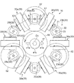
図1から図3に示す電動機10は、出力軸O1を中心とした円形状に配置された回転子20(回転子20a〜20f)と、回転子20の間のそれぞれに配置された固定子30(固定子30a〜30f)とが、仮想的な円形水平平面の上に配置されている。
回転子20の回転軸23は、固定子30が配置された円形水平平面と直交する方向に向いている。
図3に示すように、電動機10は、回転子20の回転軸23と固定子30とを挟みこむようにして保持する筐体部11を備えている。
(Embodiment 1)
An electric motor will be described as an example of the rotating electrical machine according to the first embodiment of the present invention with reference to the drawings. Note that gear teeth are omitted in FIGS. 1 to 3 and FIGS. 7 to 11.
The
The rotating
As shown in FIG. 3, the
回転子20は、永久磁石21と、永久磁石を保持する円柱状の回転子本体22とを備えている。
永久磁石21は、回転子20の軸線X1が、出力軸O1を中心とした円周方向に沿った状態を基本位置として配置され、それぞれが同期して回転する。
永久磁石21は、回転子20の軸線X1を中心に直径方向に沿って配置されていることで、一方の磁極(例えば、N極。)が回転半径方向の外側を向いていると共に、一方の磁極と反対の磁極となる他方の磁極(例えば、S極。)が一方の磁極が向いた方向と反対方向を向いている。
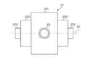
図4に示すように永久磁石21は、回転軸23(回転中心)に位置する中央部の第1部分211が太く、回転半径方向の外側に向かって第2部分212、第3部分213と細く、短くなるように形成されている。永久磁石21は、磁力が他の磁石より強いネオジム磁石が使用できる。
The
The
The
As shown in FIG. 4, the
図3に示すように、回転子本体22は、軸線位置の上端および下端に回転軸23が突出して形成され、筐体部11に回転自在に保持される。図1および図2に示すように、回転子20は、60度ごとに配置されていることで6個設けられている。
As shown in FIG. 3, the rotor
固定子30は、回転子20と同様に、固定子30の軸線X2が、出力軸O1を中心とした円周方向に沿って配置されている。図5に示すように、固定子30は、永久磁石21(図1参照)に軸線X2を向けて配置された第1巻線31(電動用巻線)と、第1巻線31の外周面に同心円で配置された第2巻線32(発電用巻線)と、第1巻線31と第2巻線32との軸線X2に配置されたコア33とを備えている。
Similarly to the
図1および図2に示すように、第1巻線31は、60度ごとに配置されていることで6個設けられている。第2巻線32も、第1巻線31と同軸に配置されていることで、6個が設けられている。第1巻線31には、図6に示す制御回路40が接続されている。
As shown in FIG. 1 and FIG. 2, six
図6に示すように、制御回路40は、センサ部41と、励磁回路部42とを備えている。
図6に示す制御回路40は、1個の第1巻線31および第2巻線32について図示しており、センサ部41は全体で1セット設けられ、励磁回路部42は、固定子30ごとに設けてもよいが、本実施の形態1では、固定子30a,30c,30d用として1つ、固定子30b,30d,30f用として1つ設けられている。
As shown in FIG. 6, the
The
センサ部41は、永久磁石21のN極の位置を検出する第1センサ部411と、永久磁石21のS極の位置を検出する第2センサ部412とを備えている。センサ部41は、図3に示すように出力軸O1に設けられている。図6および図7に示すように、第1センサ部411は、固定子30a,30c,30d用の第1センサ411aと、固定子30b,30d,30f用の第1センサ411bとが上下の位置関係となるように設けられている。同様に、第2センサ部412は、固定子30a,30c,30d用の第2センサ412aと、固定子30b,30d,30f用の第2センサ412bとが上下の位置関係となるように設けられている。
The
第1センサ部411および第2センサ部412は、出力軸O1を挟んだ回転盤41cの直径方向の両側の2ヵ所に配置され、図3に示すように発光ダイオードとフォトダイオードとによる透過型のフォトインタラプタ41aと、回転子20と共に回転して、透過型のフォトインタラプタ41aの発光ダイオードとフォトダイオードとの間を通過する遮蔽板41bとを備えている。
The
第1センサ部411および第2センサ部412の遮蔽板41bは、遮蔽板41bがドグとしてフォトインタラプタ41aを通過することで、永久磁石21の位置を検出する機能を備えている。
第1センサ部411の遮蔽板41bは、永久磁石21のN極の位置に対応させて配置され、第2センサ部412の遮蔽板41bは、永久磁石21のS極の位置に対応させて配置されている。
The shielding
The shielding
励磁回路部42は、同じ回転半径方向に位置する第1センサ部411部と第2センサ部412とを一組として、第1巻線31への通電方向を制御するものである。
励磁回路部42は、第1FET421a,421bから第3FET423a,423bまでのトランジスタにより、第1巻線31への通電方向を制御している。
第1FET421aと第3FET423aとはn型FETである。第2FET422a,422bは、p型FETである。
The
The
The
第1FET421a,421bは、ゲート端子Gが抵抗R11,R12を介してフォトインタラプタ41aに接続されている。また、第1FET421a,421bは、ソース端子Sが接地されている。
The gate terminals G of the
第2FET422a,422bは、ソース端子SがダイオードD11,D12を介して電源に接続されていると共に、コンデンサC11,C12を介して接地されている。また、第2FET422a,422bのゲート端子Gは、抵抗R21,R22を介して第1FET421a,421bのドレイン端子Dに接続されていると共に、抵抗R31,R32を介して第2FET422a,422bのソース端子Sに接続されている。第2FET422a,422bのドレイン端子Dは、ダイオードD21,D22のアノード端子Aに接続されていると共に、第3FET423a,423bのドレイン端子Dに接続されている。
The
第3FET423a,423bは、ゲート端子Gが抵抗R41,R42を介してフォトインタラプタ41aに接続されている。第3FET423a,423bのソース端子Sは接地されている。
第1巻線31の一方の配線は、第2FET422aのドレイン端子Dに接続されていると共に、第3FET423aのドレイン端子Dに接続されている。
第1巻線31の他方の配線は、第2FET422bのドレイン端子Dに接続されていると共に、第3FET423bのドレイン端子Dに接続されている。
The gate terminals G of the
One wiring of the first winding 31 is connected to the drain terminal D of the
The other wiring of the first winding 31 is connected to the drain terminal D of the
第2巻線32には、回転速度調整部50が接続されている。
回転速度調整部50は、整流部51と、消費部52とを備えている。整流部51は、ダイオードブリッジにより構成することができる。図6に示す回転速度調整部50では、整流部51に消費部52が1対1で接続されているが、回転速度調整部50は、他の第2巻線32にも整流部51が接続され、他の複数の整流部51も1個の消費部52に対して接続されている。
A rotation
The rotation
消費部52は、可変抵抗器とすることができるが、可変抵抗器の代わりに電気エネルギーを有効利用する負荷を接続してもよい。例えば、バッテリの充電回路としたり、照明器具としたり、電動機としたりすることができる。消費部52は、短絡状態から開放状態までに抵抗値を設定できるものとすることができる。
Although the
図2および図3に示すように、回転子20は、回転軸23の一方の端部に、第1駆動ギヤ61が連結されている。これらの第1駆動ギヤ61は、隣接する第1駆動ギヤ61と互いに咬み合っている。また、図1に示すように、一つ置きの回転子20(回転子20a,20c,20e)には、回転軸23の他方の端部に、回転子用ギヤである第2駆動ギヤ62が取り付けられている。出力軸O1には、連結ギヤである出力ギヤ63が設けられている。出力ギヤ63は、それぞれの第2駆動ギヤ62に外接して噛み合っている。
As shown in FIGS. 2 and 3, the
以上のように構成された本発明の実施の形態1に係る電動機の動作を図面に基づいて説明する。図6に示す制御回路40に電源が供給される。
例えば、永久磁石21のN極が第1巻線31に位置することで、センサ部41のうち、第1センサ部411のフォトインタラプタ41aに遮蔽板41bが位置する。
フォトインタラプタ41aの光の透過が遮られることで、第1センサ部411のフォトインタラプタ41aのフォトトランジスタが通電する。フォトトランジスタが通電することで、フォトインタラプタ41aに、抵抗R11,R41を介して接続された第1FET421aのゲート端子Gと、第3FET423aのゲート端子Gとは、第1FET421aと第3FET423aとがオン状態となる、第1電圧となる。
The operation of the electric motor according to Embodiment 1 of the present invention configured as described above will be described with reference to the drawings. Power is supplied to the
For example, when the N pole of the
By blocking the light transmission of the
また、第1センサ部411のフォトインタラプタ41aに遮蔽板41bが位置するときには、第2センサ部412のフォトインタラプタ41aには遮蔽板41bが位置しないので、フォトインタラプタ41aは非通電状態にある。従って、第2センサ部412のフォトインタラプタ41aに、抵抗R12,R42を介して接続された第1FET421bのゲート端子Gと、第3FET423bのゲート端子Gとは、第1FET421bと第3FET423bがオフ状態となる、第1電圧より低電圧の第2電圧(0V)となる。
When the
第1FET421bがオフ状態であるときには、第1FET421bのドレイン端子Dに抵抗R21を介して接続された第2FET422aのゲート端子Gは、電源Vssに接続された抵抗R31により第2FET422aがオフ状態となる第1電圧となる。
When the
第1FET421aがオン状態であるときには、抵抗R22が第1FET421aのドレイン端子Dに接続されているため、第2FET422bのゲート端子Gは、第2FET422bがオン状態となる、第2電圧になる。
When the
このようにして、第1FET421a,421b〜第3FET423a,423bのオン状態とオフ状態とが決定されると、電源Vssからの電流が、第2FET422bのソース端子SにダイオードD12を介して流れ込み、第2FET422bのドレイン端子Dから第1巻線31へ流れる。そして、第1巻線31の反対側から電流が、第3FET423aのドレイン端子Dからソース端子Sへ流れることで、第1巻線31は、永久磁石21のN極と反発する同極の磁界を発生する。
第1巻線31が発生した磁界により、永久磁石21のN極が反発して、回転子20が回転する。
Thus, when the ON state and the OFF state of the
Due to the magnetic field generated by the first winding 31, the N pole of the
一方、永久磁石21のS極側では、センサ部41のうち、第2センサ部412のフォトインタラプタ41aに遮蔽板41bが位置する。
フォトインタラプタ41aの光の透過が遮られることで、第2センサ部412のフォトインタラプタ41aのフォトトランジスタが通電する。フォトトランジスタが通電することで、フォトインタラプタ41aに、抵抗R12,R42を介して接続された第1FET421bのゲート端子Gと、第3FET423bのゲート端子Gとは、第1FET421bと第3FET423bとがオン状態となる、第1電圧となる。
On the other hand, on the S pole side of the
By blocking the light transmission of the
また、第2センサ部412のフォトインタラプタ41aに遮蔽板41bが位置するときには、第1センサ部411のフォトインタラプタ41aには遮蔽板41bが位置しないので、フォトインタラプタ41aは非通電状態にある。従って、第1センサ部411のフォトインタラプタ41aに、抵抗R11,R41を介して接続された第1FET421aのゲート端子Gと、第3FET423aのゲート端子Gとは、第1FET421aと第3FET423aがオフ状態となる、第2電圧となる。
Further, when the shielding
第1FET421aがオフ状態であるときには、第1FET421aのドレイン端子Dに抵抗R22を介して接続された第2FET422bのゲート端子Gは、電源Vssに接続された抵抗R32により第2FET422bがオフ状態となる第1電圧となる。
When the
第1FET421bがオン状態であるときには、抵抗R21が第1FET421bのドレイン端子Dに接続されているため、第2FET422aのゲート端子Gは、第2FET422aがオン状態となる、第2電圧になる。
When the
このようにして、第1FET421a,421b〜第3FET423a,423bのオン状態とオフ状態とが決定されると、電源Vssからの電流が、第2FET422aのソース端子SにダイオードD11を介して流れ込み、第2FET422aのドレイン端子Dから第1巻線31へ流れる。そして、第1巻線31の反対側から電流が、第3FET423bのドレイン端子Dからソース端子Sへ流れことで、第1巻線31は、永久磁石21のS極と反発する同極の磁界を発生する。
第1巻線31が発生した磁界により、永久磁石21のS極が反発して、回転子20が回転する。
Thus, when the ON state and the OFF state of the
Due to the magnetic field generated by the first winding 31, the south pole of the
次に、図7から図11に基づいて、回転子20の回転について詳細に説明する。
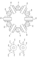
図7に示すように、回転子20a,20c,20eのN極が、固定子30a,30c,30eから離れようとするタイミングで、第1センサ部411aの遮蔽板41bがフォトインタラプタ41aへ進入する。これにより、回転子20a,20c,20e側に向いた固定子30a,30c,30eが回転子20a,20c,20eのN極に対して、同極を発生する。従って、固定子30a,30c,30eが発生する同極に、回転子20a,20c,20eの永久磁石21が反発して回転が加速される。
Next, the rotation of the
As shown in FIG. 7, the
また、固定子30a,30c,30eを挟んで、回転子20a,20c,20eと反対側の回転子20b,20d,20fのS極は、固定子30a,30c,30eのS極に向いているため、回転子20b,20d,20fは、回転子20a,20c,20eと反対方向に反発して回転する。
Further, the S poles of the
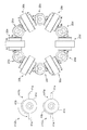
次に、図8に示すように、第1センサ部411bの遮蔽板41bがフォトインタラプタ41aへ進入する。これにより、回転子20b,20d,20fのN極が離れようとする固定子30b,30d,30fに通電される。通電により固定子30b,30d,30fは、回転子20b,20d,20fのN極に向けて同極を発生する。従って、固定子30b,30d,30fが発生する同極に、回転子20b,20d,20fの永久磁石21が反発して回転が加速される。
Next, as shown in FIG. 8, the shielding
このとき、固定子30b,30d,30fを挟んで、回転子20b,20d,20fと反対側の回転子20a,20c,20eのS極は、固定子30b,30d,30fのS極に向いているため反発して加速される。
また、固定子30a,30c,30eは図7の状態を維持して、回転子20a,20c,20eに向けてN極を発生したままであるため、固定子30全体で、それぞれの回転子20が駆動される。
At this time, the S poles of the
Further, since the
次に、図9に示すように、第1センサ部411aの遮蔽板41bがフォトインタラプタ41aから外れ離れると、固定子30a,30c,30eの通電が解除される。
次に、図10に示すように、回転子20a,20c,20eのS極が、固定子30a,30c,30eから離れようとするタイミングで、第2センサ部412aの遮蔽板41bがフォトインタラプタ41aに進入する。これにより、回転子20a,20c,20e側に向いた固定子30a,30c,30eに、これまでと反対方向に電流が流れることで、固定子30a,30c,30eは、回転子20a,20c,20eのS極に対して、同極を発生する。従って、固定子30a,30c,30eが発生する同極に、回転子20a,20c,20eの永久磁石21が反発して回転が加速される。
Next, as shown in FIG. 9, when the shielding
Next, as shown in FIG. 10, at the timing when the south poles of the
そして、図11に示すように、第2センサ部412bの遮蔽板41bがフォトインタラプタ41aへ進入する。これにより、回転子20b,20d,20fのS極が離れようとする固定子30b,30d,30fに、これまでと反対方向の電流が流れることで、固定子30b,30d,30fは、回転子20b,20d,20fのS極に向けて同極を発生する。従って、固定子30b,30d,30fが発生する同極に、回転子20b,20d,20fの永久磁石21が反発して回転が加速される。
以上のようにして、固定子30(固定子30a〜30f)のそれぞれの第1巻線31が励磁(通電)されることで、円形に配置された回転子20がそれぞれ回転し続ける。
Then, as shown in FIG. 11, the shielding
As described above, the
このように、円形状に配置された回転子20の間に固定子30が配置されているため、どの回転子20でも、両側に位置する固定子30により駆動することができる。従って、極端に固定子となる巻線を増やすことなく、効率よく回転子20を回転させることができる。
また、回転子20の回転軸23は、固定子30が配置された円形水平平面と直交する方向に向いているため、回転子20の永久磁石21を水平回転させることができる。従って、永久磁石21を反発により回転させるときに、重力方向と反対方向に反発させることがある垂直回転と比較して、永久磁石21に安定した回転を付与することができる。
Thus, since the
Moreover, since the rotating
永久磁石21は、回転半径方向の外側に向かって細くなるため、永久磁石21からの磁束を回転半径方向の外側に向かって集中させることができるので、第1巻線31に対する磁界をより強力なものとすることができる。
Since the
それぞれに回転する回転子20は、第1駆動ギヤ61により同期して回転する。また、回転子20a,20c,20eの回転により、回転軸23に設けられた第2駆動ギヤ62が回転する。そして、第2駆動ギヤ62が回転することで、第2駆動ギヤ62に外接した出力ギヤ63が回転するため、それぞれの回転子20の駆動力が集約され、出力ギヤ63の出力軸O1から力強い動力を取り出すことができる。
The
それぞれに回転する回転子20が、図1に示すような基本位置の状態にあるときには、回転子20(永久磁石21)の軸線X1と、固定子30(第1巻線31)の軸線X2とが円周状に並び、円形状に磁束が繋がる。従って、回転子20と固定子30とが円形状に配置されていることで、磁界を強めることができる。
When the respective
なお、本実施の形態1に係る電動機10では、6個の回転子20から1つの出力軸O1により出力を得ているが、6個の回転子20のそれぞれの回転軸23から動力を得てもよい。出力ギヤ63は、第1駆動ギヤ61と第2駆動ギヤ62とにより全部の回転子20からの駆動力が集約されているが、出力ギヤは、2以上の回転子20から集約されるようにしてもよい。
In the
次に、発電用巻線として機能する第2巻線32からの電流を調整する回転速度調整部50の動作について詳細に説明する。
図6に示すように、第1巻線31が通電されることで第2巻線32に電力が発生する。第2巻線32からの電流は整流部51により全波整流され、消費部52に流れる。消費部52では、第2巻線32からの電力を、設定された抵抗値によって消費する。
Next, the operation of the rotation
As shown in FIG. 6, when the first winding 31 is energized, power is generated in the second winding 32. The current from the second winding 32 is full-wave rectified by the
消費部52の消費電流が大きくなると、第1巻線31に同軸に配置された第2巻線32は、第1巻線31による電磁誘導よりも回転子20の永久磁石21による電磁誘導の方が大きくなり、発生した電流は第1巻線31を助勢する磁界を発生する。
When the consumption current of the
このとき、第1巻線31への入力電圧を一定にして、消費部52が第2巻線32から取り出す出力電流を大きくすると、消費部52への出力電圧は低下するが、回転子20の回転数は消費電流(出力電流)0Aからある電流までは低下するものの、その後、徐々に早くなる。
At this time, if the input voltage to the first winding 31 is kept constant and the output current taken out from the second winding 32 by the
このように、電動機10の回転速度調整部50により消費電流を調整することで、回転数を調整することができるので、電動機10は回転数を制御できる新規の電動機とすることができる。
As described above, since the rotational speed can be adjusted by adjusting the current consumption by the rotational
ここで、電動機10を作製して、第1巻線31への入力電圧および入力電流と、第2巻線32からの出力電圧および出力電流と、出力軸O1の回転数との関係を測定した。
第1巻線31は、銅線(Φ1.4mm)を650回巻いたものを使用した。また、第2巻線32は銅線(φ1.4mm)を巻き数1300回巻いたものを使用した。
永久磁石21は、第1部分211が直径80mm、長さ50mmであり、第2部分212が直径50mm、長さ20mm、第3部分213が直径20mm、長さ10mmである。
Here, the
The first winding 31 was a copper wire (Φ1.4 mm) wound 650 times. The second winding 32 was a copper wire (φ1.4 mm) wound with 1300 turns.
The
第1巻線31へ供給する電源VSSとして、菊水電子工業株式会社製のデジタルプログラマブル直流安定化電源「PVD150−40T」を使用した。また、第1センサ部411および第2センサ部412への電源VEEとして株式会社高砂製作所製「GP035−10」を使用した。更に、消費部52として、株式会社計測技術研究所製の多機能電子負荷装置「LN−1000C−G7」を使用した。
As the power supply VSS supplied to the first winding 31, a digital programmable direct current stabilized power supply “PVD150-40T” manufactured by Kikusui Electronics Co., Ltd. was used. Further, “GP035-10” manufactured by Takasago Seisakusho Co., Ltd. was used as the power source VEE for the
出力軸O1の回転数は、横河メータ&インスツルメンツ株式会社製のオシロスコープ「DLM2034」により測定したセンサ部41の波形に基づいた周波数から算出した。
なお、オシロスコープに接続されたプローブは、横河電機株式会社製のパッシブプローブ701939および差動プローブ700924と、ピコテクノロジー社製の電流プローブTA018を使用した。
The rotation speed of the output shaft O1 was calculated from the frequency based on the waveform of the
As the probes connected to the oscilloscope, a passive probe 701939 and a differential probe 7000924 manufactured by Yokogawa Electric Corporation and a current probe TA018 manufactured by Pico Technology were used.
(実施例1)
まず、励磁回路部42への電源VSSとして、138Vを一定に印加し、消費部52から取り出す出力電流を0Aから21Aまで増加させて、出力軸O1の回転数を測定した。
出力電流
図12に示すように、第2巻線32からの出力電流が0Aのときでは1080回転/分であったが、消費部52として機能する多機能電子負荷装置の抵抗値を低下させ、出力電流を10Aまで増加させると、回転数は徐々に低下した。
Example 1
First, 138V was applied as a power source VSS to the
As shown in FIG. 12, when the output current from the second winding 32 is 0 A, it was 1080 rotations / minute, but the resistance value of the multi-function electronic load device functioning as the
しかし、消費部52の抵抗値を更に低下させると、出力電流が徐々に増加すると共に回転数は増加する。
消費部52を短絡状態としたときには、第2巻線32が負荷となる。また、整流部51も僅かだが負荷となる。この状態では、第2巻線32からの出力電流は21Aであり、回転数は最大となる約1575回転/分であった。
このように、第2巻線32から取り出し、消費部52によって消費される出力電流によって、電動機10の回転を変化させることができる。
However, if the resistance value of the
When the
Thus, the rotation of the
(実施例2)
次に、出力軸O1の回転数を一定とし、第2巻線32からの出力電流を0Aから増加させたときの消費電力の変動について測定した。
図13に示すように、第2巻線32からの出力電流が0Aのときでは消費電力が1890.6Wであった。
次に、第1巻線31への入力電圧を調整すると共に、消費部52として機能する多機能電子負荷装置の抵抗値を低下させ、第2巻線32からの出力電流を増加させると、消費電力は徐々に増加し、出力電流が10Aのときに消費電力が2102.8Wで最大となった。
しかし、更に、第2巻線32からの出力電流が増加するように、消費部52の抵抗値を低下させると、消費電力は徐々に低下する。
そして、消費部52を短絡状態としたときには、第2巻線32からの出力電流は21Aであり、消費電力は1750.8Wと急激に低下した。
(Example 2)
Next, the variation in power consumption was measured when the rotation speed of the output shaft O1 was constant and the output current from the second winding 32 was increased from 0A.
As shown in FIG. 13, the power consumption was 1890.6 W when the output current from the second winding 32 was 0 A.
Next, the input voltage to the first winding 31 is adjusted, the resistance value of the multi-function electronic load device functioning as the
However, when the resistance value of the
And when the
従って、出力軸O1の回転数を一定とし、最大電流を第2巻線32から取り出した電動機10は、最小の消費電力となった。従って、電動機10は、回転数を一定とし、消費部52を短絡状態としたときに、消費電力を最小限に抑えることができる。
Therefore, the
なお、消費部52として機能する多機能電子負荷装置は、整流部51を介して接続されていたが、消費部52を短絡状態とするときには整流部51は省略することができる。
In addition, although the multifunctional electronic load apparatus which functions as the
なお、本実施の形態1では、回転電機を電動機10として使用していたが、回転子20の回転軸23を回転させたり、出力ギヤ63の出力軸O1を回転させたりして、電動機10を発電機として使用することも可能である。
また、本実施の形態1では、回転速度調整部50が整流部51を備えているが、第2巻線32からの電力をそのまま消費できるのであれば、消費部52を直接第2巻線32に接続してもよい。
Although the rotating electrical machine is used as the
In the first embodiment, the rotation
更に、本実施の形態1では、第1駆動ギヤ61により、それぞれの回転子20が同期して回転し、回転子20a,20c,20eの回転により第2駆動ギヤ62が回転し、そして、第2駆動ギヤ62が回転することで、出力ギヤ63が回転して、出力軸O1から出力が得られると共に、センサ部41により各回転子20の回転位置を検出していた。しかし、それぞれの回転子20の回転軸23にセンサ部41を設け、回転軸23のそれぞれから出力を得るようにするときには、第1駆動ギヤ61、第2駆動ギヤ62および出力ギヤ63は省略することができる。
Further, in the first embodiment, the
(実施の形態2)
本発明の実施の形態2に係る電動機を図面に基づいて説明する。なお、図14〜図16においては、図1と同じ構成のものは同符号を付して説明を省略する。
図14に示すように、電動機110は、回転子210と固定子30とが、仮想的な円形水平平面の上に円形状に交互に配置されている。
本実施の形態2では、回転子210と固定子30とがそれぞれ30度ごとに12個ずつ配置されている。
(Embodiment 2)
An electric motor according to
As shown in FIG. 14, in the
In the second embodiment, twelve
回転子210は、球状の永久磁石214を備えている。永久磁石214は、第1実施の形態1の電動機10(図1参照)と異なり、N極とS極とが回転半径方向の外側を向くように回転軸23に取り付けられている。永久磁石214が球状に形成されていることで、永久磁石214は、回転中心側が太く、回転半径方向の外側に向かって細くなるように形成されているため、永久磁石からの磁束を回転半径方向の外側に向かって集中させることができる。
回転軸23は、固定子30が配置された円形水平平面の半径に沿った方向に向いている。
The
The rotating
回転軸23の円形水平平面の中心側の先端には、小径の傘歯車64が設けられている。これらの傘歯車64は、固定子30が配置された円形水平平面の中心を出力軸O2とした大径の傘歯車65に噛み合っている。
12個の回転子210のうち1個の回転子210の回転軸23の基端には、センサ部41が設けられている。
A small-
A
このように電動機110が形成されていることで、センサ部41からの信号に基づいて図示しない制御回路40より、円形状に配置された固定子30の第1巻線31に、順次、通電されることにより、それぞれの固定子30の間に配置された回転子210が回転する。
回転子210の回転により、それぞれ回転子210に連結した傘歯車64が回転する。そして、傘歯車64の回転により、傘歯車65が回転するため、出力軸O2から出力を得ることができる。
Since the
As the
また、回転軸23が、垂直方向に延びておらず、固定子30が配置された円形水平平面の半径に沿った方向に向いているため、電動機110の厚みを薄くできる。
更に、回転軸23の円形水平平面の中心側の先端には、小径の傘歯車64が設けられているため、傘歯車64によって駆動され、回転する傘歯車65の直径を小さいものとすることができる。
Moreover, since the rotating
Furthermore, since a small-
なお、本実施の形態2に係る回転子210では、球状の永久磁石214を使用していたが、円柱状の永久磁石の軸線方向を、回転軸23の長さ方向に沿って配置するようにしてもよい。
In the
本発明は、複数の回転子により効率よく駆動力を得ることができるため、電動機が用いられる機械であれば好適である。 Since the present invention can efficiently obtain a driving force from a plurality of rotors, any machine using an electric motor is suitable.
10,110 電動機
11 筐体部
20,20a,20b,20c,20d,20e,20f,210 回転子
21 永久磁石
211 第1部分
212 第2部分
213 第3部分
214 永久磁石
22 回転子本体
23 回転軸
30,30a,30b,30c,30d,30e,30f 固定子
31 第1巻線
32 第2巻線
33 コア
40 制御回路
41 センサ部
411,411a,411b 第1センサ部
412,412a,412b 第2センサ部
41a フォトインタラプタ
41b 遮蔽板
41c 回転盤
42 励磁回路部
421a,421b 第1FET
422a,422b 第2FET
423a,423b 第3FET
G ゲート端子
S ソース端子
D ドレイン端子
R11,R12,R21,R22,R31,R32,R41,42 抵抗
C11,C12 コンデンサ
D11,D12,D21,D22 ダイオード
50 回転速度調整部
51 整流部
52 消費部
61 第1駆動ギヤ
62 第2駆動ギヤ
63 出力ギヤ
64,65 傘歯車
O1,O2 出力軸
X1,X2 軸線
DESCRIPTION OF SYMBOLS 10,110
422a, 422b Second FET
423a, 423b 3rd FET
G Gate terminal S Source terminal D Drain terminal R11, R12, R21, R22, R31, R32, R41, 42 Resistor C11, C12 Capacitor D11, D12, D21,
Claims (11)
前記永久磁石に軸線を向けた第1巻線を有する固定子とを備え、
前記回転子は、円形状に配置され、
前記固定子は、前記回転子の間のそれぞれに配置された回転電機。 A rotor in which the permanent magnet rotates with either one of the N or S poles facing outward in the rotational radius direction;
A stator having a first winding with an axis directed to the permanent magnet,
The rotor is arranged in a circular shape,
The stator is a rotating electrical machine disposed between each of the rotors.
前記永久磁石の一方の磁極が対向位置にある前記第1巻線に、前記一方の磁極と同極の磁界を発生させるための電流を通電する制御回路を備え、
前記制御回路は、前記永久磁石の他方の磁極と対向位置にある前記第1巻線に、前記他方の磁極と同極の磁界を発生させるための電流を通電する機能を備えた請求項1または2記載の回転電機。 In the permanent magnet, the other magnetic pole that is the opposite magnetic pole to the one magnetic pole is oriented in the opposite direction to the direction in which the one magnetic pole is oriented,
A control circuit for energizing a current to generate a magnetic field having the same polarity as the one magnetic pole in the first winding in which the one magnetic pole of the permanent magnet is in an opposing position;
2. The control circuit according to claim 1, wherein the control circuit has a function of supplying a current for generating a magnetic field having the same polarity as that of the other magnetic pole to the first winding at a position opposite to the other magnetic pole of the permanent magnet. 2. The rotating electrical machine according to 2.
Applications Claiming Priority (2)
| Application Number | Priority Date | Filing Date | Title |
|---|---|---|---|
| JP2016087327 | 2016-04-25 | ||
| JP2016087327 | 2016-04-25 |
Publications (1)
| Publication Number | Publication Date |
|---|---|
| JP2017200416A true JP2017200416A (en) | 2017-11-02 |
Family
ID=60239640
Family Applications (1)
| Application Number | Title | Priority Date | Filing Date |
|---|---|---|---|
| JP2016183223A Pending JP2017200416A (en) | 2016-04-25 | 2016-09-20 | Rotary electric machine |
Country Status (1)
| Country | Link |
|---|---|
| JP (1) | JP2017200416A (en) |
Cited By (4)
| Publication number | Priority date | Publication date | Assignee | Title |
|---|---|---|---|---|
| CN110518763A (en) * | 2019-07-26 | 2019-11-29 | 福一开集团有限公司 | Two-phase inertia double-return circuit electric motivation |
| DE112018004555T5 (en) | 2017-10-16 | 2020-05-28 | Denso Corporation | Heat pump cycle |
| CN114640230A (en) * | 2022-03-23 | 2022-06-17 | 冯天玉 | Gear type multi-rotor generator |
| WO2023144859A1 (en) * | 2022-01-25 | 2023-08-03 | 須山弘次 | Magnet reversal motor and power generator |
Citations (10)
| Publication number | Priority date | Publication date | Assignee | Title |
|---|---|---|---|---|
| JPS6218954A (en) * | 1985-05-24 | 1987-01-27 | エヌ・ベ−・フイリツプス・フル−イランペンフアブリケン | Single-phase synchronous motor |
| JPH04101602A (en) * | 1990-08-16 | 1992-04-03 | Honda Motor Co Ltd | Motor vehicle |
| JPH04222445A (en) * | 1990-12-25 | 1992-08-12 | Kyocera Corp | Rotary driver for ring body |
| JPH08237917A (en) * | 1995-01-04 | 1996-09-13 | Philips Electron Nv | Electric driving device and shaver containing it |
| JPH0946969A (en) * | 1995-08-02 | 1997-02-14 | Kichinosuke Nagashio | Electric motor unit |
| JPH09219960A (en) * | 1996-02-14 | 1997-08-19 | Tai-Haa Yan | Common magnetic-pole-circuit type rotating machine having plurality of rotors |
| US5780950A (en) * | 1994-10-18 | 1998-07-14 | Yang; Tai-Her | Co-axial magnetic circuit type compound rotor electrical machine |
| WO2014057842A1 (en) * | 2012-10-12 | 2014-04-17 | 株式会社カネコ | Electromagnetic rotating driving device |
| WO2015199105A1 (en) * | 2014-06-24 | 2015-12-30 | 日立オートモティブシステムズ株式会社 | Rotating electrical machine |
| JP5920905B1 (en) * | 2015-12-25 | 2016-05-18 | 株式会社空 | Electric motor |
-
2016
- 2016-09-20 JP JP2016183223A patent/JP2017200416A/en active Pending
Patent Citations (10)
| Publication number | Priority date | Publication date | Assignee | Title |
|---|---|---|---|---|
| JPS6218954A (en) * | 1985-05-24 | 1987-01-27 | エヌ・ベ−・フイリツプス・フル−イランペンフアブリケン | Single-phase synchronous motor |
| JPH04101602A (en) * | 1990-08-16 | 1992-04-03 | Honda Motor Co Ltd | Motor vehicle |
| JPH04222445A (en) * | 1990-12-25 | 1992-08-12 | Kyocera Corp | Rotary driver for ring body |
| US5780950A (en) * | 1994-10-18 | 1998-07-14 | Yang; Tai-Her | Co-axial magnetic circuit type compound rotor electrical machine |
| JPH08237917A (en) * | 1995-01-04 | 1996-09-13 | Philips Electron Nv | Electric driving device and shaver containing it |
| JPH0946969A (en) * | 1995-08-02 | 1997-02-14 | Kichinosuke Nagashio | Electric motor unit |
| JPH09219960A (en) * | 1996-02-14 | 1997-08-19 | Tai-Haa Yan | Common magnetic-pole-circuit type rotating machine having plurality of rotors |
| WO2014057842A1 (en) * | 2012-10-12 | 2014-04-17 | 株式会社カネコ | Electromagnetic rotating driving device |
| WO2015199105A1 (en) * | 2014-06-24 | 2015-12-30 | 日立オートモティブシステムズ株式会社 | Rotating electrical machine |
| JP5920905B1 (en) * | 2015-12-25 | 2016-05-18 | 株式会社空 | Electric motor |
Cited By (5)
| Publication number | Priority date | Publication date | Assignee | Title |
|---|---|---|---|---|
| DE112018004555T5 (en) | 2017-10-16 | 2020-05-28 | Denso Corporation | Heat pump cycle |
| CN110518763A (en) * | 2019-07-26 | 2019-11-29 | 福一开集团有限公司 | Two-phase inertia double-return circuit electric motivation |
| WO2023144859A1 (en) * | 2022-01-25 | 2023-08-03 | 須山弘次 | Magnet reversal motor and power generator |
| CN114640230A (en) * | 2022-03-23 | 2022-06-17 | 冯天玉 | Gear type multi-rotor generator |
| CN114640230B (en) * | 2022-03-23 | 2023-09-22 | 冯天玉 | A gear-type multi-rotor generator |
Similar Documents
| Publication | Publication Date | Title |
|---|---|---|
| JP2017200416A (en) | Rotary electric machine | |
| KR102051115B1 (en) | Electric motor | |
| KR20170125865A (en) | Disc rotor type and axial flux type rotating electric machine | |
| JP2019092330A (en) | Brushless synchronous generator | |
| CN110945763B (en) | Rotating electrical machine | |
| JP2012125021A (en) | Axial gap rotating machine | |
| JP6283199B2 (en) | Electric motor | |
| JP2017175904A (en) | Turning type pole piece module and magnet gear comprising the same | |
| GB2574792A (en) | Rotationally balanced electric motor with air-core stator coils | |
| JP6243073B1 (en) | Rotating electric machine | |
| TWI652878B (en) | Current gain generator | |
| JP7276934B2 (en) | Electric motor | |
| JP7179392B1 (en) | Rotating electric machine | |
| JP2016146722A (en) | Rotary machine | |
| JP2021122171A (en) | Stepping motor | |
| JPWO2009044485A1 (en) | Generator | |
| RU181317U1 (en) | ELECTRIC GENERATOR HAVING A CENTRAL MAGNETIC SHAFT | |
| CN2372817Y (en) | brushless generator | |
| JP2022156002A (en) | Electric motor | |
| TWM529981U (en) | Multi-pole multi-output low resistance brushless power generation device | |
| KR20260029072A (en) | High-efficiency power generator with reduced rotational load | |
| TW202040915A (en) | Motor/motor-generator having multiple permanent magnet pairs in forward arrangement with outer rotors by configurating the ratio of the number of permanent magnets being larger than that of the iron cores and increasing the number of coil turns to increase the magnetic flux density and improve the energy conversion efficiency | |
| JP2016146721A (en) | Rotary machine | |
| JP2013255408A (en) | Highly efficient power generation apparatus and power generation method with less cogging force | |
| JP2010130894A (en) | Generator |
Legal Events
| Date | Code | Title | Description |
|---|---|---|---|
| A621 | Written request for application examination |
Free format text: JAPANESE INTERMEDIATE CODE: A621 Effective date: 20180207 |
|
| A977 | Report on retrieval |
Free format text: JAPANESE INTERMEDIATE CODE: A971007 Effective date: 20181114 |
|
| A131 | Notification of reasons for refusal |
Free format text: JAPANESE INTERMEDIATE CODE: A131 Effective date: 20181204 |
|
| A02 | Decision of refusal |
Free format text: JAPANESE INTERMEDIATE CODE: A02 Effective date: 20190604 |