JP2017200420A - Rotary driving device - Google Patents
Rotary driving device Download PDFInfo
- Publication number
- JP2017200420A JP2017200420A JP2016224306A JP2016224306A JP2017200420A JP 2017200420 A JP2017200420 A JP 2017200420A JP 2016224306 A JP2016224306 A JP 2016224306A JP 2016224306 A JP2016224306 A JP 2016224306A JP 2017200420 A JP2017200420 A JP 2017200420A
- Authority
- JP
- Japan
- Prior art keywords
- drive device
- rotary drive
- rotor hub
- inertia
- shaft
- Prior art date
- Legal status (The legal status is an assumption and is not a legal conclusion. Google has not performed a legal analysis and makes no representation as to the accuracy of the status listed.)
- Granted
Links
Images

Classifications
-
- G—PHYSICS
- G02—OPTICS
- G02B—OPTICAL ELEMENTS, SYSTEMS OR APPARATUS
- G02B26/00—Optical devices or arrangements for the control of light using movable or deformable optical elements
- G02B26/08—Optical devices or arrangements for the control of light using movable or deformable optical elements for controlling the direction of light
- G02B26/10—Scanning systems
- G02B26/105—Scanning systems with one or more pivoting mirrors or galvano-mirrors
-
- G—PHYSICS
- G02—OPTICS
- G02B—OPTICAL ELEMENTS, SYSTEMS OR APPARATUS
- G02B7/00—Mountings, adjusting means, or light-tight connections, for optical elements
- G02B7/18—Mountings, adjusting means, or light-tight connections, for optical elements for prisms; for mirrors
- G02B7/182—Mountings, adjusting means, or light-tight connections, for optical elements for prisms; for mirrors for mirrors
- G02B7/1821—Mountings, adjusting means, or light-tight connections, for optical elements for prisms; for mirrors for mirrors for rotating or oscillating mirrors
-
- H—ELECTRICITY
- H02—GENERATION; CONVERSION OR DISTRIBUTION OF ELECTRIC POWER
- H02K—DYNAMO-ELECTRIC MACHINES
- H02K1/00—Details of the magnetic circuit
- H02K1/06—Details of the magnetic circuit characterised by the shape, form or construction
- H02K1/22—Rotating parts of the magnetic circuit
- H02K1/27—Rotor cores with permanent magnets
- H02K1/2706—Inner rotors
-
- H—ELECTRICITY
- H02—GENERATION; CONVERSION OR DISTRIBUTION OF ELECTRIC POWER
- H02K—DYNAMO-ELECTRIC MACHINES
- H02K1/00—Details of the magnetic circuit
- H02K1/06—Details of the magnetic circuit characterised by the shape, form or construction
- H02K1/22—Rotating parts of the magnetic circuit
- H02K1/27—Rotor cores with permanent magnets
- H02K1/2786—Outer rotors
- H02K1/2787—Outer rotors the magnetisation axis of the magnets being perpendicular to the rotor axis
- H02K1/2788—Outer rotors the magnetisation axis of the magnets being perpendicular to the rotor axis the rotor consisting of a single magnet or two or more axially juxtaposed single magnets
-
- H—ELECTRICITY
- H02—GENERATION; CONVERSION OR DISTRIBUTION OF ELECTRIC POWER
- H02K—DYNAMO-ELECTRIC MACHINES
- H02K7/00—Arrangements for handling mechanical energy structurally associated with dynamo-electric machines, e.g. structural association with mechanical driving motors or auxiliary dynamo-electric machines
- H02K7/08—Structural association with bearings
-
- H—ELECTRICITY
- H02—GENERATION; CONVERSION OR DISTRIBUTION OF ELECTRIC POWER
- H02K—DYNAMO-ELECTRIC MACHINES
- H02K7/00—Arrangements for handling mechanical energy structurally associated with dynamo-electric machines, e.g. structural association with mechanical driving motors or auxiliary dynamo-electric machines
- H02K7/08—Structural association with bearings
- H02K7/083—Structural association with bearings radially supporting the rotary shaft at both ends of the rotor
-
- H—ELECTRICITY
- H02—GENERATION; CONVERSION OR DISTRIBUTION OF ELECTRIC POWER
- H02K—DYNAMO-ELECTRIC MACHINES
- H02K7/00—Arrangements for handling mechanical energy structurally associated with dynamo-electric machines, e.g. structural association with mechanical driving motors or auxiliary dynamo-electric machines
- H02K7/14—Structural association with mechanical loads, e.g. with hand-held machine tools or fans
Landscapes
- Engineering & Computer Science (AREA)
- Power Engineering (AREA)
- Physics & Mathematics (AREA)
- General Physics & Mathematics (AREA)
- Optics & Photonics (AREA)
- Connection Of Motors, Electrical Generators, Mechanical Devices, And The Like (AREA)
- Motor Or Generator Frames (AREA)
- Sliding-Contact Bearings (AREA)
- Mounting Of Bearings Or Others (AREA)
- Rolling Contact Bearings (AREA)
- Permanent Magnet Type Synchronous Machine (AREA)
- Mechanical Optical Scanning Systems (AREA)
- Optical Radar Systems And Details Thereof (AREA)
Abstract
【課題】回転駆動装置の回転を安定させる。【解決手段】回転駆動装置1Aは、ステータ22Aを有する静止部2Aと、上下に延びる中心軸9Aを中心として軸受部23Aを介して回転可能に支持される回転部3Aと、を含む。回転部は、シャフト31Aの周囲において環状に拡がる第1ロータハブ部331Aと、第1ロータハブ部よりも下側に配置される第2ロータハブ部332Aと、第1ロータハブ部に固定され、第1ロータハブ部よりも比重の大きい第1イナーシャ部361Aと、第2ロータハブ部362Aに固定され、第2ロータハブ部よりも比重の大きい第2イナーシャ部と、を含む。静止部は、シャフトを回転可能に支持するスリーブ部24Aを含む。第1イナーシャ部は、ベース部21Aよりも上側に位置し、第2イナーシャ部は、ベース部よりも下側に位置する。回転部の重心は、上側軸受部の上端よりも下側、かつ、下側軸受部の下端よりも上側に位置する。【選択図】図1The rotation of a rotary drive device is stabilized. A rotary drive device 1A includes a stationary portion 2A having a stator 22A, and a rotating portion 3A supported rotatably via a bearing portion 23A around a central axis 9A extending vertically. The rotating portion is fixed to the first rotor hub portion, the first rotor hub portion 331A that extends annularly around the shaft 31A, the second rotor hub portion 332A that is disposed below the first rotor hub portion, and the first rotor hub portion. A first inertia part 361A having a greater specific gravity than the first rotor part, and a second inertia part fixed to the second rotor hub part 362A and having a greater specific gravity than the second rotor hub part. The stationary portion includes a sleeve portion 24A that rotatably supports the shaft. The first inertia part is located above the base part 21A, and the second inertia part is located below the base part. The center of gravity of the rotating part is located below the upper end of the upper bearing part and above the lower end of the lower bearing part. [Selection] Figure 1
Description
本発明は、回転駆動装置に関する。 The present invention relates to a rotary drive device.
従来、ヘッドマウントディスプレイ(HMD)等に用いられる、位置認識を行うためのスキャナー装置には、スキャナー装置を回転させるためのモータが搭載される。従来のモータについては、例えば、特開2009−124935号公報に、記載されている。特開2009−124935号公報のモータでは、ロータハブ、ロータマグネット、およびシャフトを有するロータ部の重心が、スリーブが挿入されるベースの筒状絞り部よりも、軸方向上部に位置する。そして、スリーブとベースとを固定する接着剤の溜り部の位置を、同様に筒状絞り部の軸方向上部に設けることによって、ロータ部の重心付近の部材間の接着強度が上がる。これにより、モータの耐衝撃性を向上させることができる。
しかしながら、特開2009−124935号公報のモータでは、比重の大きいロータ部の重心が、モータの軸方向上側に位置する。これにより、モータの回転が不安定になる虞がある。 However, in the motor disclosed in Japanese Patent Application Laid-Open No. 2009-124935, the center of gravity of the rotor portion having a large specific gravity is positioned on the upper side in the axial direction of the motor. Thereby, there exists a possibility that rotation of a motor may become unstable.
本発明の目的は、回転駆動装置において比重の大きい回転部の重心を、静止部と回転部との間に介在する上下の軸受の間に位置させることにより、モータの回転を安定させることができる装置を提供することである。 An object of the present invention is to stabilize the rotation of a motor by positioning the center of gravity of a rotating part having a large specific gravity in a rotary drive device between upper and lower bearings interposed between the stationary part and the rotating part. Is to provide a device.
本願の例示的な発明は、回転駆動装置であって、ステータを有する静止部と、前記ステータと対向するマグネットを有し、前記静止部に対して、上下に延びる中心軸を中心として軸受部を介して回転可能に支持される回転部と、を含み、前記回転部は、前記中心軸に沿って配置されるシャフトと、前記シャフトの周囲において環状に拡がる第1ロータハブ部と、前記第1ロータハブ部よりも下側に配置され、前記シャフトの周囲において環状に拡がる第2ロータハブ部と、前記第1ロータハブ部に直接または間接的に固定され、前記第1ロータハブ部よりも比重の大きい第1イナーシャ部と、前記第2ロータハブ部に直接または間接的に固定され、前記第2ロータハブ部よりも比重の大きい第2イナーシャ部と、を含み、前記静止部は、前記シャフトを回転可能に支持するスリーブ部と、前記スリーブ部を直接または間接的に支持するベース部と、を含み、前記第1イナーシャ部は、前記ベース部よりも上側に位置し、前記第2イナーシャ部は、前記ベース部よりも下側に位置し、前記軸受部は、上側軸受部と、前記上側軸受部よりも下側に位置する下側軸受部と、を含み、前記回転部の重心は、前記上側軸受部の上端よりも下側、かつ、前記下側軸受部の下端よりも上側に位置する回転駆動装置である。 An exemplary invention of the present application is a rotary drive device, which includes a stationary part having a stator and a magnet facing the stator, and a bearing part with a center axis extending vertically as a center with respect to the stationary part. A rotating part supported rotatably through the shaft, the rotating part being arranged along the central axis, a first rotor hub part extending annularly around the shaft, and the first rotor hub A second rotor hub portion disposed below the shaft and extending annularly around the shaft; and a first inertia having a specific gravity greater than that of the first rotor hub portion, which is fixed directly or indirectly to the first rotor hub portion. And a second inertia part fixed directly or indirectly to the second rotor hub part and having a specific gravity larger than that of the second rotor hub part, and the stationary part A sleeve portion that rotatably supports the shaft, and a base portion that directly or indirectly supports the sleeve portion, wherein the first inertia portion is located above the base portion, and the second inertia portion The portion is located below the base portion, the bearing portion includes an upper bearing portion and a lower bearing portion located below the upper bearing portion, and the center of gravity of the rotating portion is The rotary drive device is located below the upper end of the upper bearing portion and above the lower end of the lower bearing portion.
本願の例示的な発明によれば、回転駆動装置のベース部の上側と下側に、それぞれ比重の大きいイナーシャ部を配置することにより、回転部の重心をモータの中心近くに位置させることができる。また、当該重心が、静止部と回転部との間に介在する上側軸受部の上端と下側軸受部の下端との間に位置することにより、モータの回転を安定させることができる。 According to the exemplary invention of the present application, the center of gravity of the rotating part can be positioned near the center of the motor by disposing the inertia part having a large specific gravity on the upper side and the lower side of the base part of the rotation driving device. . The center of gravity is positioned between the upper end of the upper bearing portion and the lower end of the lower bearing portion interposed between the stationary portion and the rotating portion, so that the rotation of the motor can be stabilized.
以下、本発明の例示的な実施形態について、図面を参照しながら説明する。なお、本願では、後述するモータの中心軸と平行な方向を「軸方向」、モータの中心軸に直交する方向を「径方向」、モータの中心軸を中心とする円弧に沿う方向を「周方向」、とそれぞれ称する。また、本願では、軸方向を上下方向とし、モータに対して光源側を上として、各部の形状や位置関係を説明する。ただし、この上下方向の定義により、本発明に係る回転駆動装置の使用時の向きを限定する意図はない。 Hereinafter, exemplary embodiments of the present invention will be described with reference to the drawings. In the present application, a direction parallel to the motor central axis, which will be described later, is referred to as an “axial direction”, a direction orthogonal to the motor central axis is referred to as a “radial direction”, and a direction along an arc centered on the motor central axis is referred to as “circumferential direction”. Direction ". In the present application, the shape and positional relationship of each part will be described with the axial direction as the vertical direction and the light source side as the upper side with respect to the motor. However, the definition of the vertical direction is not intended to limit the orientation when the rotary drive device according to the present invention is used.
また、本願において「平行な方向」とは、略平行な方向も含む。また、本願において「直交する方向」とは、略直交する方向も含む。 Further, in the present application, the “parallel direction” includes a substantially parallel direction. Further, in the present application, the “perpendicular direction” includes a substantially orthogonal direction.
<1.第1実施形態>
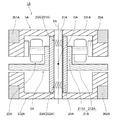
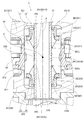
図1は、第1実施形態に係る回転駆動装置1Aの縦断面図である。この回転駆動装置1Aは、光源から入射する入射光を反射するミラーを有する回転体を回転させるために用いられる。図1に示すように、回転駆動装置1Aは、静止部2Aと、回転部3Aとを有する。回転部3Aは、静止部2Aに対して、上下に延びる中心軸9Aを中心として、後述する軸受部23Aを介して回転可能に支持される。
<1. First Embodiment>
FIG. 1 is a longitudinal sectional view of a
静止部2Aは、ベース部21A、ステータ22A、軸受部23A、およびスリーブ部24Aを有する。
The
ベース部21Aは、ステータホルダ211Aとベース本体212Aとを有する。ステータホルダ211Aは、外周面においてステータ22Aを保持する。ベース本体212Aは、ステータホルダ211Aの下端部付近から、中心軸9Aに対して直交する方向に広がる。
The
軸受部23Aは、上側軸受部231Aと下側軸受部232Aとを有する。下側軸受部232Aは、上側軸受部231Aよりも下側に位置する。
The
スリーブ部24Aは、軸方向に略円筒状に延び、後述するシャフト31Aの周囲において、軸受部23Aを介してシャフト31Aを回転可能に支持する部材である。スリーブ部24Aは、ステータホルダ211Aの径方向内側に挿入され、例えば接着剤で、ステータホルダ211Aに固定されることによって、支持される。なお、スリーブ部24Aは、ステータホルダ211Aに直接支持されてもよく、別の部材を介して間接的に支持されてもよい。
The
回転部3Aは、シャフト31A、第1ロータハブ部331A、第2ロータハブ部332A、マグネット35A、第1イナーシャ部361A、および第2イナーシャ部362Aを有する。
The rotating
シャフト31Aは、中心軸9Aに沿って配置される円柱状の部材である。
The
第1ロータハブ部331Aは、シャフト31Aの上端部付近の周囲において環状に拡がる。第2ロータハブ部332Aは、第1ロータハブ部331Aよりも下側に配置され、シャフト31Aの下端部付近の周囲において環状に拡がる。
The first
マグネット35Aは、略円筒状に形成され、ステータ22Aと径方向に対向する磁極面を有する。
The
第1イナーシャ部361Aは、第1ロータハブ部331Aよりも比重の大きい環状の部材である。第1イナーシャ部361Aは、ベース部21Aよりも上側に位置し、第1ロータハブ部331Aに、例えば接着剤で、固定される。なお、第1イナーシャ部361Aは、第1ロータハブ部331Aに直接固定されてもよく、別の部材を介して間接的に固定されてもよい。第2イナーシャ部362Aは、第2ロータハブ部332Aよりも比重の大きい環状の部材である。第2イナーシャ部362Aは、ベース部21Aよりも下側に位置し、第2ロータハブ部332Aに、例えば接着剤で、固定される。なお、第2イナーシャ部362Aは、第2ロータハブ部332Aに直接固定されてもよく、別の部材を介して間接的に固定されてもよい。
The
回転部3Aの重心CAは、上側軸受部231Aの上端よりも下側、かつ、下側軸受部232Aの下端よりも上側に位置する。上述のとおり、回転部3Aの上部と下部に比重の大きい第1イナーシャ部361Aおよび第2イナーシャ部362Aを配置することにより、回転部3Aの重心CAを回転駆動装置1Aの中心付近に位置させることができる。これにより、回転駆動装置1Aの回転が安定する。
The center of gravity CA of the
<2.第2実施形態>
<2−1.回転駆動装置の構成>
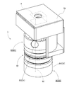
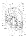
図2は、第2実施形態に係る回転駆動装置1および光源6の斜視図である。また、図3は、第2実施形態に係る回転駆動装置1を、中心軸9を含む平面で切断した状態を示す断面斜視図である。当該回転駆動装置1は、光源6から入射する入射光60を反射する、後述するミラーを回転させながら、当該ミラーにおいて反射された反射光を、レンズを介して回転駆動装置1の外部に出射する装置である。なお、本実施形態の光源6は、回転駆動装置1の外部に設けられている。ただし、光源6は回転駆動装置1に含まれていてもよい。
<2. Second Embodiment>
<2-1. Configuration of Rotation Drive Device>
FIG. 2 is a perspective view of the
図2および図3に示すように、回転駆動装置1は、回転体80と、回転体80を支持するモータ10と、を有する。回転体80は、第1回転体81と第2回転体82とを含む。第1回転体81は、入射光60の一部を回転駆動装置1の外部に反射する第1ミラー61を有する。第2回転体82は、入射光60の他の一部を回転駆動装置1の外部に反射する第2ミラー62を有する。
As shown in FIGS. 2 and 3, the
<2−2.モータの構成>
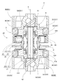
続いて、上記のモータ10のより詳細な構成について説明する。図4は、第2実施形態に係る回転駆動装置1の縦断面図である。また、図5は、第2実施形態に係る回転駆動装置1の部分縦断面図である。図4に示すとおり、モータ10は、静止部2と回転部3とを有する。静止部2は、回転駆動装置1が配置される筐体等(図示省略)に対して、相対的に静止している。回転部3は、静止部2に対して、上下に延びる中心軸9を中心として、後述する軸受部23を介して回転可能に支持されている。
<2-2. Motor configuration>
Next, a more detailed configuration of the
本実施形態の静止部2は、ベース部21、ステータ22、および後述する回転部3のシャフト31を回転可能に支持する軸受部23を有する。
The
ベース部21は、第1回転体81と第2回転体82との間において、中心軸9に対して直交する方向に広がっている。ベース部21は、ステータホルダ211とベース本体212とを有する。
The
ベース本体212は、ステータホルダ211を支持する板状の部材である。ベース本体212の材料には、例えばアルミニウム合金やステンレス等の金属が用いられる。ベース本体212は、ステータホルダ211の周囲から径方向外側へ向けて拡がる。モータ10の使用時には、例えば、回転駆動装置1が配置される筐体等にベース本体212がねじ止め等で固定される。なお、ベース本体212の上面または下面に、モータ10に駆動電流を供給するための回路基板(図示省略)が配置されてもよい。
The
ステータホルダ211は、軸方向に延びる円筒状の部材である。ステータホルダ211の下端部は、ベース本体212の貫通孔210内に挿入され、ベース本体212に対してかしめにより固定される。ただし、ベース本体212に対するステータホルダ211の固定方法は、溶接等の他の方法であってもよい。また、ベース本体212とステータホルダ211とが、一繋がりの部材となっていてもよい。
The
ステータ22は、ステータコア41と複数のコイル42とを有する電機子である。ステータ22は、ベース部21の少なくとも一部よりも上方に位置する。ステータコア41は、例えば、珪素鋼板等の電磁鋼板が軸方向に積層された積層鋼板からなる。ステータコア41は、ステータホルダ211の外周面に、例えば接着剤で固定されることによって、支持される。また、ステータコア41は、円環状のコアバック411と、コアバック411から径方向外側へ向けて突出した複数のティース412と、を有する。複数のコイル42は、複数のティース412の周囲に巻かれた導線の集合体である。モータ10の駆動電流は、外部電源(図示省略)から、上述の回路基板および当該導線を介して、コイル42に供給される。複数のティース412および複数のコイル42は、好ましくは、中心軸9を中心とした周方向に、円環状に略等間隔に配列される。
The
図5に示すとおり、軸受部23は、スリーブ部24と、第1キャップ251と、第2キャップ252と、を有する。
As shown in FIG. 5, the bearing
スリーブ部24は、後述するシャフト31の周囲において、軸方向に略円筒状に延びる。スリーブ部24は、ステータホルダ211の径方向内側に挿入され、例えば接着剤で、ステータホルダ211に固定される。スリーブ部24の上端部は、ステータホルダ211の上端部およびステータ22の上端部よりも、軸方向上側に位置する。また、スリーブ部24の下端部は、ステータホルダ211の下端部およびステータ22の下端部よりも、軸方向下側に位置する。なお、スリーブ部24は、複数の部材で構成されていてもよい。
The
第1キャップ251は、第1筒状部71と第1平板部72とを有する。第1筒状部71は、スリーブ部24の上端部付近に固定され、上方へ向けて略円筒状に延びる。第1平板部72は、第1筒状部71の上端部付近から、径方向内側に拡がる。
The
第2キャップ252は、第2筒状部73と第2平板部74とを有する。第2筒状部73は、スリーブ部24の下端部付近に固定され、下方へ向けて略円筒状に延びる。第2平板部74は、第2筒状部73の下端部付近から、径方向内側に拡がる。
The
軸受部23の構成については、詳細を後述する。
Details of the configuration of the bearing
本実施形態の回転部3は、シャフト31、環状部32、ロータハブ部33、ヨーク34、マグネット35、およびイナーシャ部36を有する。
The
シャフト31は、中心軸9に沿って配置され、スリーブ部24の径方向内側において、軸方向に延びる円筒状の部材である。シャフト31の材料には、例えば、ステンレス鋼等の金属が使用される。シャフト31の材料は、強磁性または非磁性のいずれであってもよい。シャフト31の上端部は、スリーブ部24および第1キャップ251の上端部よりも上方へ突出している。また、シャフト31の下端部は、スリーブ部24および第2キャップ252の下端部よりも下方へ突出している。シャフト31の外周面と、スリーブ部24の内周面241とは、僅かな間隙を介して径方向に対向する。また、シャフト31は、上下方向にシャフト31を貫通するシャフト貫通孔310を有する。なお、シャフト31は、後述するロータハブ部33と、単一の部材であってもよい。
The
なお、シャフト31の上端部を含む少なくとも一部は、軸受部23よりも上側に位置する。シャフト31の下端部を含む少なくとも一部は、軸受部23よりも下側に位置する。これにより、シャフト31の上部と下部に、後述するロータハブ部33を介して、後述するイナーシャ部36を固定できる。したがって、モータ10の回転と同時に、上下のイナーシャ部36を回転させることができる。このため、モータ10の回転をより安定させることができる。
Note that at least a part of the
環状部32は、第1環状部321と第2環状部322とを有する。第1環状部321は、少なくとも一部がベース本体212よりも上側において、シャフト31の外周面に固定され、全周に亘って径方向外側へ突出する部材である。また、第2環状部322は、少なくとも一部がベース本体212よりも下側において、シャフト31の外周面に固定され、全周に亘って径方向外側へ突出する部材である。なお、シャフト31と環状部32とは、単一の部材であってもよい。
The
なお、第1環状部321の下部の外周面と、スリーブ部24の上部の、軸方向に対して傾斜している上部傾斜面242とは、斜め方向に僅かな間隙を介して対向する。また、第2環状部322の上部の外周面と、スリーブ部24の下部の、軸方向に対して傾斜している下部傾斜面243とは、斜め方向に僅かな間隙を介して対向する。
Note that the outer peripheral surface of the lower portion of the first
さらに、第1環状部321の上部の外周面と、第1キャップ251の第1筒状部71の内周面とは、径方向に僅かな間隙を介して対向する。また、第2環状部322の下部の外周面と、第2キャップ252の第2筒状部73の内周面とは、径方向に僅かな間隙を介して対向する。
Furthermore, the outer peripheral surface of the upper part of the first
ロータハブ部33は、第1ロータハブ部331と第2ロータハブ部332とを有する。第1ロータハブ部331は、シャフト31の上端部の周縁部から、シャフト31の周囲において径方向外側へ向けて環状に拡がっている。第2ロータハブ部332は、第1ロータハブ部331よりも下側に配置され、シャフト31の下端部の周縁部から、シャフト31の周囲において径方向外側へ向けて環状に拡がっている。
The
ロータハブ部33の材料には、例えば、アルミニウム合金、または強磁性または非磁性のステンレス鋼が使用される。シャフト31の上端部は、軸受部23よりも上側の位置において、第1ロータハブ部331に固定されている。具体的には、シャフト31の上端部は、第1ロータハブ部331の径方向内側に設けられた、第1ロータハブ部331を軸方向に貫く貫通孔に圧入される。また、シャフト31の下端部は、軸受部23よりも下側の位置において、第2ロータハブ部332に固定されている。具体的には、シャフト31の下端部は、第2ロータハブ部332の径方向内側に設けられた、第2ロータハブ部332を軸方向に貫く貫通孔に圧入される。モータ10の回転時には、シャフト31、第1ロータハブ部331、第2ロータハブ部332、および後述するイナーシャ部36が同時に回転する。これにより、モータ10の回転を安定させることができる。
As a material of the
ヨーク34は、後述するマグネット35の径方向外側に固定され、マグネット35を保持する円筒状の部材である。ヨーク34の内周面には、マグネット35の外周面が固定される。ヨーク34は、中心軸9と略同軸に配置される。ヨーク34の上端部は、第1ロータハブ部331の下部に、例えば接着剤またはかしめによって固定される。ヨーク34の材料には、鉄などの比較的質量の大きな磁性体が用いられる。このため、回転部3の慣性力を増加させることができる。その結果、モータ10の駆動時における回転部3の姿勢が、さらに安定する。
The
マグネット35は、ヨーク34の内周面において、例えば接着剤で固定される。本実施形態のマグネット35には、円環状の永久磁石が用いられている。マグネット35は、略円筒形状であり、ステータ22の径方向外側に位置する。マグネット35の内周面には、N極とS極とが周方向に交互に着磁される。また、マグネット35の内周面は、複数のティース412の径方向外側の端面と、僅かな間隙を介して径方向に対向する。ただし、円環状のマグネット35に代えて、複数のマグネットが用いられてもよい。複数のマグネットを用いる場合には、N極の磁極面とS極の磁極面とが周方向に交互に並ぶように、ヨーク34の内周面に配置すればよい。なお、本実施形態のマグネット35は、上述のとおりヨーク34を介して第1ロータハブ部331に間接的に固定されている。しかし、マグネット35は、ヨーク34を介さずに、第1ロータハブ部331に直接固定されていてもよい。
The
イナーシャ部36は、第1イナーシャ部361と第2イナーシャ部362とを有する。第1イナーシャ部361は、後述する第1回転体81の下側に固定される環状の部材である。第2イナーシャ部362は、後述する第2回転体82の上側に固定される環状の部材である。第1イナーシャ部361は、例えば接着剤で、第1ロータハブ部331の外周面に固定される。また、第2イナーシャ部362は、例えば接着剤で、第2ロータハブ部332の外周面に固定される。したがって、第1イナーシャ部361および第2イナーシャ部362は、モータ10の駆動時には、ロータハブ部33を含む回転部3および回転体80とともに回転する。なお、第1イナーシャ部361は、第1ロータハブ部331に直接固定されてもよく、別の部材を介して間接的に固定されてもよい。また、第2イナーシャ部362は、第2ロータハブ部332に直接固定されてもよく、別の部材を介して間接的に固定されてもよい。
The
第1イナーシャ部361および第2イナーシャ部362の材料には、例えばステンレス等の金属が用いられる。第1イナーシャ部361の比重は、第1ロータハブ部331および第1回転体81の比重よりも大きい。また、第2イナーシャ部362の比重は、第2ロータハブ部332および第2回転体82の比重よりも大きい。このため、第1イナーシャ部361と第2イナーシャ部362を設けると、第1イナーシャ部361と第2イナーシャ部362が無い場合よりも、モータ10の駆動時における回転部3の慣性力が増加する。したがって、回転部3の姿勢を安定させることができる。なお、第1イナーシャ部361および第2イナーシャ部362は、樹脂製であってもよい。
As the material of the
なお、このモータ10では、第1イナーシャ部361の下面が、第1ロータハブ部331の下部において径方向に拡がる第1フランジ部333の上面に接触する。これにより、第1イナーシャ部361の軸方向の位置が安定する。さらに、このモータ10では、第1フランジ部333の上側かつ第1回転体81の下側に、第1イナーシャ部361が配置される。すなわち、第1イナーシャ部361が、第1ロータハブ部331と第1回転体81との間に挟み込まれる。これにより、第1イナーシャ部361の軸方向の位置が、より安定する。また、第2イナーシャ部362の上面が、第2ロータハブ部332の上部において径方向に拡がる第2フランジ部334の下面に接触する。これにより、第2イナーシャ部362の軸方向の位置が安定する。
In the
また、このモータ10では、第2フランジ部334の下側かつ第2回転体82の上側に、第2イナーシャ部362が配置される。すなわち、第2イナーシャ部362が、第2ロータハブ部332と第2回転体82との間に挟み込まれる。これにより、第2イナーシャ部362の軸方向の位置が、より安定する。このように、上下のイナーシャ部36の軸方向の位置が安定すれば、イナーシャ部36の傾きが抑制される。したがって、モータ10の駆動時における回転部3の姿勢が、さらに安定する。また、第1イナーシャ部361は、ベース部21よりも上側に位置し、第2イナーシャ部362は、ベース部21よりも下側に位置する。これにより、回転部3の上部と下部とに、質量がバランスよく分布する。したがって、モータ10の駆動時における回転部3の姿勢が、さらに安定する。
In the
このようなモータ10において、上述の回路基板を介してコイル42に駆動電流を供給すると、複数のティース412に磁束が生じる。そして、ティース412とマグネット35との間の磁束の作用により、静止部2と回転部3との間に周方向のトルクが発生する。その結果、静止部2に対して回転部3が、中心軸9を中心として回転する。ロータハブ部33に固定されたイナーシャ部36、および回転部3に支持された後述する回転体80は、回転部3とともに、中心軸9を中心として回転する。
In such a
<2−3.軸受部の構成>
続いて、軸受部23の詳細な構成について説明する。
<2-3. Configuration of bearing section>
Subsequently, a detailed configuration of the bearing
上述のとおり、スリーブ部24、第1キャップ251、および第2キャップ252を含む静止部2と、シャフト31、第1環状部321、および第2環状部322を含む回転部3とは、間隙を介して対向している。また、当該間隙には、潤滑オイル50が介在している。モータ10の回転時には、スリーブ部24の内周面に設けられた動圧溝によって、潤滑オイル50に流体動圧が誘起される。これにより、回転部3が静止部2から支持されることで、安定して回転することができる。すなわち、本実施形態では、静止部2側の部材であるスリーブ部24、第1キャップ251、および第2キャップ252と、回転部3側の部材であるシャフト31、第1環状部321、および第2環状部322と、当該間隙に介在する潤滑オイル50とで、軸受機構が構成されている。
As described above, the
潤滑オイル50には、例えば、ポリオールエステル系オイルやジエステル系オイルが使用される。シャフト31、第1環状部321、および第2環状部322を含む回転部3は、スリーブ部24、第1キャップ251、および第2キャップ252を有する軸受部23に対して、潤滑オイル50を介して回転可能に支持されつつ、モータ10の駆動時には中心軸9を中心として回転する。
For the lubricating
なお、潤滑オイル50は、第1環状部321の上部の外周面と第1キャップ251の第1筒状部71の内周面との間の間隙、第1環状部321の下部の外周面とスリーブ部24の上部の軸方向に対して傾斜している上部傾斜面242との間の間隙、およびシャフト31の外周面とスリーブ部24の上部の内周面241Uとの間の間隙において、連続して存在する。また、シャフト31の外周面とスリーブ部24の下部の内周面241Lとの間の間隙、第2環状部322の上部の外周面とスリーブ部24の下部の軸方向に対して傾斜している下部傾斜面243との間の間隙、および第2環状部322の下部の外周面と第2キャップ252の第2筒状部73の内周面との間の間隙において、連続して存在する。但し、潤滑オイル50は、シャフト31の外周面とスリーブ24の内周面241との間の間隙において、軸方向中央付近には存在しない。
The lubricating
このように、軸受部23は、潤滑オイル50が、静止部2と回転部3とが対向する当該間隙において、2以上の箇所に分かれて存在する、所謂パーシャルフィル構造を有している。潤滑オイル50は、モータ10の、ベース本体212よりも上側に存在する上側潤滑オイル501と、ベース本体212よりも下側に存在する下側潤滑オイル502と、を含む。なお、本実施形態のシャフト31の外周面とスリーブ部24の中央部付近の内周面241Mとの間の間隙は、潤滑オイル50が介在しない空間となっている。
As described above, the bearing
つまり、当該軸受機構は、上側軸受部231と下側軸受部232とに分かれて設けられている。上側軸受部231は、スリーブ部24のベース本体212よりも上側の部位、および第1キャップ251を含む静止部2側の部材と、シャフト31のベース本体212よりも上側の部位、および第1環状部321を含む回転部3側の部材と、上側潤滑オイル501とで、構成されている。また、下側軸受部232は、スリーブ部24のベース本体212よりも下側の部位、および第2キャップ252を含む静止部2側の部材と、シャフト31のベース本体212よりも下側の部位、および第2環状部322を含む回転部3側の部材と、下側潤滑オイル502とで、構成されている。
That is, the bearing mechanism is provided separately in the
また、静止部2は、上側軸受部231の少なくとも一部と、径方向に重なる。静止部2は、後述する回転体80の重心Cと径方向に重なる。これにより、回転駆動装置1がさらに安定して回転することができる。ただし、静止部2は、必ずしも上側軸受部231の少なくとも一部と、径方向に重なっている必要は無い。すなわち、静止部2は、下側軸受部232の少なくとも一部と、径方向に重なっていても良い。この場合、回転体80の重心Cがさらに下方に位置することで、回転駆動装置1がより安定して回転することができる。
The
このように、少なくとも一部がベース本体212よりも上側に位置する間隙に存在する上側潤滑オイル501に流体動圧が誘起される上側軸受部231と、少なくとも一部がベース本体212よりも下側に位置する間隙に存在する下側潤滑オイル502に流体動圧が誘起される下側軸受部232と、の間にベース本体212が配置される。これにより、回転部3の上部と下部とが、軸受部23にバランスよく支持される。したがって、モータ10の駆動時における回転駆動装置1の姿勢が、さらに安定する。
As described above, the
なお、本実施形態では、回転部3の重心Cは、上側軸受部231の上端231Uよりも下側、かつ、下側軸受部232の下端232Lよりも上側に位置する。上述のとおり、回転部3の上部と下部に比重の大きい第1イナーシャ部361および第2イナーシャ部362を配置することにより、このように回転部3の重心Cをモータ10の中心付近に位置させることができる。これにより、モータ10の回転が安定する。さらに、回転部3の重心Cは、上側軸受部231の下端231Lよりも下側に位置することが好ましい。また、回転部3の重心Cは、下側軸受部232の上端232Uよりも上側に位置することが望ましい。これにより、モータ10の回転がさらに安定する。
In the present embodiment, the center of gravity C of the
なお、軸受機構は、潤滑オイル50が、第1環状部321の上部の外周面と第1キャップ251の第1筒状部71の内周面との間の間隙、第1環状部321の下部の外周面とスリーブ部24の上部の軸方向に対して傾斜している上部傾斜面242との間の間隙、シャフト31の外周面とスリーブ部24の内周面241との間の間隙、第2環状部322の上部の外周面と、スリーブ部24の下部の、軸方向に対して傾斜している下部傾斜面243との間の間隙、および第2環状部322の下部の外周面と第2キャップ252の第2筒状部73の内周面との間の間隙、すなわち、ベース本体212の上側および下側に位置する、静止部2と回転部3とが対向する間隙において、連続して存在する所謂フルフィル構造を有していてもよい。これにより、モータ10の回転時に衝撃が加わった場合においても、静止部2と回転部3との接触を抑制することができる。
In the bearing mechanism, the lubricating
なお、潤滑オイル50の上側の界面は、第1環状部321の上部の外周面と第1キャップ251の第1筒状部71の内周面との間の間隙に位置し、第1ロータハブ部331と径方向に重なる。また、潤滑オイル50の下側の界面は、第2環状部322の下部の外周面と第2キャップ252の第2筒状部73の内周面との間の間隙に位置し、第2ロータハブ部332と径方向に重なる。
The upper interface of the lubricating
さらに、潤滑オイル50がフルフィル構造を有している場合において、上側軸受部231および下側軸受部232のうち、シャフト31の外周面と、スリーブ部24の内周面241を含む静止部2の少なくとも一部とが、潤滑オイル50が存在する間隙(ラジアル間隙)を介して径方向に対向するラジアル軸受部233は、回転部3の重心Cと径方向に重なる。これにより、回転駆動装置1がさらに安定して回転することができる。
Further, when the lubricating
<2−4.回転体の構成>
続いて、回転体80の構成について詳細を説明する。
<2-4. Configuration of rotating body>
Subsequently, the configuration of the
図2および図3に戻る。回転駆動装置1の上方には、光源6を内蔵するフレーム70が配置される。フレーム70は、回転駆動装置1が配置される筐体等に固定される。光源6より、モータ10の中心軸9に沿って下方へ進む入射光60が出射される。
Returning to FIG. 2 and FIG. A
回転体80は、第1回転体81と第2回転体82とを有する。第1回転体81は、モータ10の回転部3の上端部に支持され、回転部3とともに中心軸9を中心として回転する。第2回転体82は、モータ10の回転部3の下端部に支持され、回転部3とともに中心軸9を中心として回転する。第1回転体81および第2回転体82の材料には、後述する第1ミラー61および第2ミラー62を除き、例えば樹脂が用いられる。
The rotating
図3に示すとおり、第1回転体81の下面810は、第1ロータハブ部331および第1イナーシャ部361の上面に、例えば係合、または接着剤等を用いて固定されている。第1回転体81は、第1縦円筒部811、第1ミラー61、第1横円筒部812、および第1レンズ813を有する。
As shown in FIG. 3, the
第1縦円筒部811は、モータ10の中心軸9と略同軸に配置され、軸方向に延びる円筒状の部位である。第1縦円筒部811の下端部と、シャフト貫通孔310の上端部とは、軸方向に対向する。すなわち、第1縦円筒部811の径方向内側の空洞814は、シャフト貫通孔310と、軸方向に連続している。第1縦円筒部811の径方向内側の空洞814およびシャフト貫通孔310は、光導波路となっている。
The first vertical
第1ミラー61は、少なくとも一部が軸受部23よりも上側における中心軸9上に位置している。本実施形態では、第1ミラー61は、第1縦円筒部811の下端部とシャフト31の上端部との間において、第1回転体81を構成する樹脂部材に固定されている。また、第1ミラー61は、軸方向および後述する第1径方向に対して、45°に傾斜している。第1ミラー61は、透過率と反射率がほぼ等しいハーフミラーである。なお、第1ミラー61は、上述のとおり第1イナーシャ部361よりも上側において、第1回転体81を構成する樹脂部材を介して回転部3に間接的に固定されることによって支持されてもよく、回転部3に直接固定されることによって支持されてもよい。
The
第1横円筒部812は、第1縦円筒部811の下端部付近から径方向外側(第1径方向D1)に延びる円筒状の部材である。第1横円筒部812の径方向内側の空洞815は、第1縦円筒部811の径方向内側の空洞814と直角に連結されている。第1横円筒部812の径方向内側の空洞815と、第1ミラー61とは、第1径方向D1に重なる。
The first horizontal
第1レンズ813は第1横円筒部812の径方向外側の端部を覆う。
The
光源6から出射された入射光60は、第1縦円筒部811よりも上方から入射し、第1縦円筒部811の径方向内側の空洞814を中心軸9に沿って下方へ進む。そして、入射光60のうちの一部が第1ミラー61において反射され、入射光60のうちの他の一部は第1ミラー61を透過して、さらに下方へ進む。第1ミラー61において反射された第1反射光63は、第1横円筒部812の径方向内側の空洞815を第1径方向D1に進み、第1レンズ813を介して回転駆動装置1の外部へ出射される。
第2回転体82の上面820は、第2ロータハブ部332および第2イナーシャ部362の下面に、例えば係合、または接着剤等を用いて固定されている。第2回転体82は、第2縦円筒部821、第2ミラー62、第2横円筒部822、および第2レンズ(図示省略)を有する。
The
第2縦円筒部821は、モータ10の中心軸9と略同軸に配置され、軸方向に延びる円筒状の部位である。第2縦円筒部821の上端部と、シャフト貫通孔310の下端部とは、軸方向に対向する。すなわち、第2縦円筒部821の径方向内側の空洞824は、シャフト貫通孔310と、軸方向に連続している。第2縦円筒部821の径方向内側の空洞824は、光導波路となっている。
The second vertical
第2ミラー62は、少なくとも一部が軸受部23よりも下側における中心軸9上に位置している。本実施形態では、第2ミラー62は、第2縦円筒部821の上端部とシャフト31の下端部との間において、第2回転体82を構成する樹脂部材に固定されている。また、第2ミラー62は、軸方向および後述する第2径方向に対して、45°に傾斜している。第2ミラー62には、全ミラーが用いられている。なお、第2ミラー62は、上述のとおり第2イナーシャ部362よりも下側において、第2回転体82を構成する樹脂部材を介して回転部3に間接的に固定されることによって支持されてもよく、回転部3に直接固定されることによって支持されてもよい。
The
第2横円筒部822は、第2縦円筒部821の上端部付近から径方向外側(第2径方向D2)に延びる円筒状の部材である。第2横円筒部822の径方向内側の空洞825は、第2縦円筒部821の径方向内側の空洞824と直角に連結されている。第2横円筒部822の径方向内側の空洞825と、第2ミラー62とは、第2径方向D2に重なる。
The second horizontal
第2レンズ(図示省略)は第2横円筒部822の径方向外側の端部を覆う。
The second lens (not shown) covers the radially outer end of the second horizontal
上述のとおり、入射光60のうちの第1ミラー61を透過した他の一部は、さらに下方へ進む。そして、シャフト貫通孔310の内側を通過して、第2ミラー62において反射される。さらに、第2ミラー62において反射された第2反射光64は、第2横円筒部822の径方向内側の空洞825を第2径方向D2に進み、第2レンズ(図示省略)を介して回転駆動装置1の外部へ出射される。
As described above, the other part of the incident light 60 that has passed through the
第1回転体81の第1ミラー61と、第2回転体82の第2ミラー62は、モータ10の回転部3とともに中心軸9を中心として回転しつつ、光源6からの入射光60を反射して、反射光を外部へ出射する。入射光60の一部がシャフト貫通孔310を通ることで、1つの光源6から1方向に入射する入射光を、上下の回転体80で反射しつつ、回転しながら外部へ出射することができる。これにより、広範囲に効率よく光を照射することが可能となる。また、1つの光源6および1つのモータ10を用いて広範囲の照射を行うことができ、配置スペースに制限がある場合でも適用できる。
The
なお、第1回転体81の第1ミラー61において反射される第1反射光63が外部に出射される第1径方向D1と、第2回転体82の第2ミラー62において反射される第2反射光64が外部に出射される第2径方向D2とは、互いに異なる。これにより、モータ10の回転時において、当該2方向の出射光が照射対象物に到達するまでの時間差を生じさせることで、空間内における照射対象物の立体的な位置認識が可能となる。
The first reflected light 63 reflected by the
なお、第1回転体81の外周面816は、第1ミラー61の表面よりも反射率が低く、第2回転体82の外周面826は、第2ミラー62の表面よりも反射率が低い。これにより、光源6からの入射光60が乱反射することを抑制できる。
The outer
また、本実施形態では、第1回転体81と第2回転体82とは、互いに同じ形状を有している。これにより、当該第1ミラー61および第2ミラー62を除く樹脂製の第1回転体81および第2回転体82を、1つの金型を用いて成型することができ、コスト低減につながる。なお、第1回転体81と第2回転体82とは、互いに異なる形状を有していてもよい。例えば、第2回転体82の第2縦円筒部821は、径方向内側の空洞824を有さない構造であってもよい。
In the present embodiment, the first
<3.変形例>
以上、本発明の例示的な実施形態について説明したが、本発明は上記の実施形態に限定されるものではない。
<3. Modification>
As mentioned above, although exemplary embodiment of this invention was described, this invention is not limited to said embodiment.
図6は、一変形例に係る回転駆動装置1Bの縦断面図である。図6の例では、ベース部21Bよりも軸方向上側と下側における、スリーブ部24Bの内周面とシャフト31Bの外周面との間に、転がり軸受が介在している。モータ10Bの回転部3Bは、転がり軸受である軸受部23Bを介して、静止部2Bに対して中心軸9Bを中心として回転可能に支持されている。
FIG. 6 is a longitudinal sectional view of a
なお、静止部と回転部との間には、すべり軸受等の他の構成の軸受が介在してもよい。 Note that a bearing having another configuration such as a slide bearing may be interposed between the stationary portion and the rotating portion.
また、第1実施形態の回転駆動装置1には、マグネット35がステータ22よりも径方向外側に位置する、所謂アウターロータ型のモータ10が使用されていた。しかし、マグネットがステータよりも径方向内側に位置する、所謂インナーロータ型のモータが使用されてもよい。
Further, in the
また、本発明の上下の回転体に替えて、モータの上下にインペラまたはディスクを搭載してもよく、本発明の回転駆動装置を、空気流を供給するファンモータまたはディスクを回転させるスピンドルモータとして使用してもよい。 Further, instead of the upper and lower rotating bodies of the present invention, impellers or disks may be mounted on the upper and lower sides of the motor, and the rotation driving device of the present invention is used as a fan motor for supplying air flow or a spindle motor for rotating the disk. May be used.
また、各部品の細部の形状については、本願の各図に示された形状と、相違していてもよい。また、上記の実施形態や変形例に登場した各要素を、矛盾が生じない範囲で、適宜に組み合わせてもよい。 Further, the shape of the details of each part may be different from the shape shown in each drawing of the present application. Moreover, you may combine suitably each element which appeared in said embodiment and modification in the range which does not produce inconsistency.
本発明は、回転駆動装置に利用できる。 The present invention can be used for a rotary drive device.
1,1A,1B 回転駆動装置
2,2A,2B 静止部
3,3A,3B 回転部
6 光源
9,9A,9B 中心軸
10,10B モータ
21,21A,21B ベース部
22,22A ステータ
23,23A,23B 軸受部
24,24A,24B スリーブ部
31,31A,31B シャフト
32 環状部
33 ロータハブ部
34 ヨーク
35,35A マグネット
36 イナーシャ部
41 ステータコア
42 コイル
50 潤滑オイル
60 入射光
61 第1ミラー
62 第2ミラー
63 第1反射光
64 第2反射光
70 フレーム
71 第1筒状部
72 第1平板部
73 第2筒状部
74 第2平板部
80 回転体
81 第1回転体
82 第2回転体
210 貫通孔
211,211A ステータホルダ
212,212A ベース本体
231,231A 上側軸受部
232,232A 下側軸受部
233 ラジアル軸受部
241 内周面
242 上部傾斜面
243 下部傾斜面
251 第1キャップ
252 第2キャップ
310 シャフト貫通孔
321 第1環状部
322 第2環状部
331,331A 第1ロータハブ部
332,332A 第2ロータハブ部
333 第1フランジ部
334 第2フランジ部
361,361A 第1イナーシャ部
362,362A 第2イナーシャ部
411 コアバック
412 ティース
501 上側潤滑オイル
502 下側潤滑オイル
810 下面
811 第1縦円筒部
812 第1横円筒部
813 第1レンズ
814 空洞
815 空洞
816 外周面
820 上面
821 第2縦円筒部
822 第2横円筒部
824 空洞
825 空洞
826 外周面
C,CA 重心
D1 第1径方向
D2 第2径方向
DESCRIPTION OF SYMBOLS 1,1A, 1B Rotation drive device 2,2A, 2B Stationary part 3,3A, 3B Rotation part 6 Light source 9,9A, 9B Center axis 10,10B Motor 21,21A, 21B Base part 22,22A Stator 23,23A, 23B Bearing portion 24, 24A, 24B Sleeve portion 31, 31A, 31B Shaft 32 Annular portion 33 Rotor hub portion 34 Yoke 35, 35A Magnet 36 Inertia portion 41 Stator core 42 Coil 50 Lubricating oil 60 Incident light 61 First mirror 62 Second mirror 63 First reflected light 64 Second reflected light 70 Frame 71 First cylindrical portion 72 First flat plate portion 73 Second cylindrical portion 74 Second flat plate portion 80 Rotating body 81 First rotating body 82 Second rotating body 210 Through hole 211 , 211A Stator holder 212, 212A Base body 231, 231A Upper shaft Portion 232, 232A Lower bearing portion 233 Radial bearing portion 241 Inner peripheral surface 242 Upper inclined surface 243 Lower inclined surface 251 First cap 252 Second cap 310 Shaft through hole 321 First annular portion 322 Second annular portion 331, 331A First 1 rotor hub portion 332, 332A second rotor hub portion 333 first flange portion 334 second flange portion 361, 361A first inertia portion 362, 362A second inertia portion 411 core back 412 teeth 501 upper lubricating oil 502 lower lubricating oil 810 lower surface 811 First vertical cylindrical portion 812 First horizontal cylindrical portion 813 First lens 814 Cavity 815 Cavity 816 Outer surface 820 Upper surface 821 Second vertical cylindrical portion 822 Second horizontal cylindrical portion 824 Cavity 825 Cavity 826 Outer surface C, CA Center of gravity D1 First One radial direction D Second radial direction
Claims (17)
ステータを有する静止部と、
前記ステータと対向するマグネットを有し、前記静止部に対して、上下に延びる中心軸を中心として軸受部を介して回転可能に支持される回転部と、
を含み、
前記回転部は、
前記中心軸に沿って配置されるシャフトと、
前記シャフトの周囲において環状に拡がる第1ロータハブ部と、
前記第1ロータハブ部よりも下側に配置され、前記シャフトの周囲において環状に拡がる第2ロータハブ部と、
前記第1ロータハブ部に直接または間接的に固定され、前記第1ロータハブ部よりも比重の大きい第1イナーシャ部と、
前記第2ロータハブ部に直接または間接的に固定され、前記第2ロータハブ部よりも比重の大きい第2イナーシャ部と、
を含み、
前記静止部は、
前記シャフトを回転可能に支持するスリーブ部と、
前記スリーブ部を直接または間接的に支持するベース部と、
を含み、
前記第1イナーシャ部は、前記ベース部よりも上側に位置し、
前記第2イナーシャ部は、前記ベース部よりも下側に位置し、
前記軸受部は、
上側軸受部と、
前記上側軸受部よりも下側に位置する下側軸受部と、
を含み、
前記回転部の重心は、前記上側軸受部の上端よりも下側、かつ、前記下側軸受部の下端よりも上側に位置する回転駆動装置。 A rotary drive device,
A stationary part having a stator;
A rotating part having a magnet facing the stator and supported rotatably with respect to the stationary part through a bearing part around a central axis extending vertically;
Including
The rotating part is
A shaft disposed along the central axis;
A first rotor hub portion extending annularly around the shaft;
A second rotor hub portion disposed below the first rotor hub portion and extending annularly around the shaft;
A first inertia part fixed directly or indirectly to the first rotor hub part and having a higher specific gravity than the first rotor hub part;
A second inertia part fixed directly or indirectly to the second rotor hub part and having a specific gravity greater than that of the second rotor hub part;
Including
The stationary part is
A sleeve portion for rotatably supporting the shaft;
A base portion that directly or indirectly supports the sleeve portion;
Including
The first inertia part is located above the base part,
The second inertia part is located below the base part,
The bearing portion is
An upper bearing,
A lower bearing portion located below the upper bearing portion;
Including
The rotary drive device is such that the center of gravity of the rotating part is located below the upper end of the upper bearing part and above the lower end of the lower bearing part.
前記重心は、前記下側軸受部の上端よりも上側に位置する回転駆動装置。 The rotary drive device according to claim 1,
The center of gravity is a rotary drive device located above the upper end of the lower bearing portion.
前記重心は、前記上側軸受部の下端よりも下側に位置する回転駆動装置。 The rotary drive device according to claim 1,
The center of gravity is a rotary drive device positioned below the lower end of the upper bearing portion.
前記上側軸受部の少なくとも一部は、前記ベース部よりも上側に位置し、
前記下側軸受部の少なくとも一部は、前記ベース部よりも下側に位置する回転駆動装置。 It is a rotation drive device given in any 1 paragraph of Claims 1-3,
At least a part of the upper bearing portion is located above the base portion,
At least a part of the lower bearing portion is a rotational drive device located below the base portion.
前記静止部は、前記上側軸受部の少なくとも一部と径方向に重なる回転駆動装置。 The rotary drive device according to any one of claims 1 to 4,
The stationary part is a rotary drive device that overlaps at least a part of the upper bearing part in a radial direction.
前記静止部は、前記下側軸受部の少なくとも一部と径方向に重なる回転駆動装置。 The rotary drive device according to any one of claims 1 to 4,
The stationary portion is a rotational drive device that overlaps at least a part of the lower bearing portion in a radial direction.
前記第1イナーシャ部よりも上側において、前記回転部に直接または間接的に支持される第1ミラーと、
前記第2イナーシャ部よりも下側において、前記回転部に直接または間接的に支持される第2ミラーと、
を含み、
第1ミラーは、光源から入射する入射光の一部を前記回転駆動装置の外部に反射し、
第2ミラーは、前記入射光の他の一部を前記回転駆動装置の外部に反射する回転駆動装置。 The rotary drive device according to any one of claims 1 to 6, further comprising:
A first mirror that is directly or indirectly supported by the rotating part above the first inertia part;
A second mirror that is directly or indirectly supported by the rotating part below the second inertia part;
Including
The first mirror reflects a part of incident light incident from the light source to the outside of the rotation driving device,
The second mirror is a rotary drive device that reflects another part of the incident light to the outside of the rotary drive device.
前記シャフトの上端を含む少なくとも一部は、前記軸受部よりも上側に位置し、
前記シャフトの下端を含む少なくとも一部は、前記軸受部よりも下側に位置する回転駆動装置。 The rotary drive device according to any one of claims 1 to 7,
At least a part including the upper end of the shaft is located above the bearing portion,
At least a part including a lower end of the shaft is a rotational drive device positioned below the bearing portion.
前記シャフトは、前記軸受部よりも上側の位置において、前記第1ロータハブ部に固定され、前記軸受部よりも下側の位置において、前記第2ロータハブ部に固定される回転駆動装置。 The rotary drive device according to claim 8,
The shaft is fixed to the first rotor hub part at a position above the bearing part, and fixed to the second rotor hub part at a position below the bearing part.
前記マグネットは、前記ステータよりも径方向外側に位置する回転駆動装置。 The rotary drive device according to any one of claims 1 to 9,
The magnet is a rotational drive device located on the radially outer side than the stator.
前記マグネットは、前記ステータよりも径方向内側に位置する回転駆動装置。 The rotary drive device according to any one of claims 1 to 9,
The magnet is a rotational drive device positioned radially inward of the stator.
前記軸受部において
前記静止部と、前記回転部とが、潤滑オイルが存在する間隙を介して対向し、前記潤滑オイルに流体動圧が誘起される回転駆動装置。 The rotary drive device according to any one of claims 1 to 11,
In the bearing portion, the stationary portion and the rotating portion are opposed to each other through a gap in which lubricating oil is present, and a fluid drive pressure is induced in the lubricating oil.
前記潤滑オイルは、前記間隙において連続して存在する回転駆動装置。 The rotary drive device according to claim 12,
The rotational drive device in which the lubricating oil is continuously present in the gap.
前記潤滑オイルは、前記間隙において2以上の箇所に分かれて存在する回転駆動装置。 The rotary drive device according to claim 12,
The rotational drive device in which the lubricating oil exists in two or more locations in the gap.
前記軸受部は、転がり軸受である回転駆動装置。 The rotary drive device according to any one of claims 1 to 11,
The said bearing part is a rotation drive device which is a rolling bearing.
前記第1イナーシャ部および前記第2イナーシャ部は、樹脂製である回転駆動装置。 The rotary drive device according to any one of claims 1 to 15,
The first inertia part and the second inertia part are rotational drive devices made of resin.
前記第1イナーシャ部および前記第2イナーシャ部は、金属製である回転駆動装置。 The rotary drive device according to any one of claims 1 to 15,
The first inertia part and the second inertia part are rotation driving devices made of metal.
Applications Claiming Priority (2)
| Application Number | Priority Date | Filing Date | Title |
|---|---|---|---|
| US201662328844P | 2016-04-28 | 2016-04-28 | |
| US62/328,844 | 2016-04-28 |
Publications (2)
| Publication Number | Publication Date |
|---|---|
| JP2017200420A true JP2017200420A (en) | 2017-11-02 |
| JP6938895B2 JP6938895B2 (en) | 2021-09-22 |
Family
ID=60156979
Family Applications (2)
| Application Number | Title | Priority Date | Filing Date |
|---|---|---|---|
| JP2016224288A Withdrawn JP2017198965A (en) | 2016-04-28 | 2016-11-17 | Rotary drive apparatus |
| JP2016224306A Expired - Fee Related JP6938895B2 (en) | 2016-04-28 | 2016-11-17 | Rotation drive |
Family Applications Before (1)
| Application Number | Title | Priority Date | Filing Date |
|---|---|---|---|
| JP2016224288A Withdrawn JP2017198965A (en) | 2016-04-28 | 2016-11-17 | Rotary drive apparatus |
Country Status (3)
| Country | Link |
|---|---|
| US (2) | US10175475B2 (en) |
| JP (2) | JP2017198965A (en) |
| CN (2) | CN206640438U (en) |
Families Citing this family (6)
| Publication number | Priority date | Publication date | Assignee | Title |
|---|---|---|---|---|
| JP2018120159A (en) * | 2017-01-27 | 2018-08-02 | 日本電産株式会社 | Rotary driving device and method of manufacturing rotary driving device |
| CN108363200A (en) * | 2017-01-27 | 2018-08-03 | 日本电产株式会社 | rotating driving device |
| US20190094526A1 (en) * | 2017-09-28 | 2019-03-28 | Nidec Corporation | Rotary drive apparatus |
| JP6738916B1 (en) * | 2019-01-30 | 2020-08-12 | エーエーシー コミュニケーション テクノロジーズ(ジョウシュウ)カンパニーリミテッド | Lens drive |
| CN111427148B (en) * | 2020-04-01 | 2022-02-22 | 北京航空航天大学 | Maxwell force driven quick deflection mirror |
| JP2021180536A (en) * | 2020-05-11 | 2021-11-18 | 日本電産サンキョー株式会社 | motor |
Citations (6)
| Publication number | Priority date | Publication date | Assignee | Title |
|---|---|---|---|---|
| JPS6317564U (en) * | 1986-07-17 | 1988-02-05 | ||
| JPH0429554A (en) * | 1990-05-22 | 1992-01-31 | Fuji Electric Co Ltd | Stepping motor |
| JPH04244768A (en) * | 1991-01-31 | 1992-09-01 | Toshiba Lighting & Technol Corp | Optical scanner |
| JPH06351190A (en) * | 1993-06-08 | 1994-12-22 | Hitachi Ltd | Spindle motor |
| JP2012152098A (en) * | 2010-12-27 | 2012-08-09 | Nippon Densan Corp | Spindle motor, disk drive device, and method of manufacturing spindle motor |
| JP2015163021A (en) * | 2014-02-28 | 2015-09-07 | ミネベア株式会社 | stepping motor |
Family Cites Families (19)
| Publication number | Priority date | Publication date | Assignee | Title |
|---|---|---|---|---|
| JPS5967844A (en) * | 1982-10-08 | 1984-04-17 | Toshiba Corp | Disk motor with brush |
| US5367399A (en) * | 1992-02-13 | 1994-11-22 | Holotek Ltd. | Rotationally symmetric dual reflection optical beam scanner and system using same |
| JP3413851B2 (en) | 1992-07-07 | 2003-06-09 | オリンパス光学工業株式会社 | Optical scanning image information detection device |
| JPH07294838A (en) * | 1994-04-27 | 1995-11-10 | Ebara Corp | Polygon mirror rotating body and polygon mirror scanner motor having this rotating body |
| US5734515A (en) * | 1994-08-08 | 1998-03-31 | Reliance Electric Industrial Company | Apparatus for positioning an optical line of sight within a hemispheric region |
| JPH11183826A (en) * | 1997-12-19 | 1999-07-09 | Fuji Xerox Co Ltd | Light deflector |
| EP0977068A3 (en) * | 1998-07-31 | 2000-04-19 | Loyal Port Company Limited | Image inverting device |
| JP2002071809A (en) * | 2000-09-04 | 2002-03-12 | Mitsubishi Electric Corp | Scanning device, scanning method and non-contact type measuring device |
| JP4477220B2 (en) * | 2000-11-20 | 2010-06-09 | オリンパス株式会社 | Spindle motor |
| JP4797489B2 (en) * | 2005-07-26 | 2011-10-19 | 日本電産株式会社 | Color wheel rotation device |
| JP2007198420A (en) * | 2006-01-24 | 2007-08-09 | Nippon Densan Corp | Method for manufacturing bearing unit and motor mounting the bearing unit |
| TWI343689B (en) * | 2006-12-28 | 2011-06-11 | Delta Electronics Inc | Permanent magnet rotary structure of electric machinery |
| EP1965225A3 (en) * | 2007-02-28 | 2009-07-15 | Denso Wave Incorporated | Laser radar apparatus for three-dimensional detection of objects |
| JP5212690B2 (en) * | 2007-05-10 | 2013-06-19 | 日本電産株式会社 | Fluid dynamic bearing mechanism, motor and recording disk drive |
| US7880354B2 (en) | 2007-10-25 | 2011-02-01 | Panasonic Corporation | Spindle motor, information recording and reproducing apparatus that makes use of same, and method for manufacturing spindle motor |
| JP5747632B2 (en) * | 2011-04-26 | 2015-07-15 | 日本電産株式会社 | Centrifugal fan |
| CN102801264B (en) * | 2012-09-04 | 2015-02-11 | 魏乐汉 | Permanent magnet laminated motor |
| DE102013002423A1 (en) * | 2013-02-11 | 2014-08-14 | Carl Zeiss Microscopy Gmbh | Optics arrangement and light microscope |
| JP6277406B2 (en) * | 2013-09-27 | 2018-02-14 | 日本電産株式会社 | Mirror rotating device |
-
2016
- 2016-11-17 JP JP2016224288A patent/JP2017198965A/en not_active Withdrawn
- 2016-11-17 JP JP2016224306A patent/JP6938895B2/en not_active Expired - Fee Related
-
2017
- 2017-04-05 US US15/479,517 patent/US10175475B2/en not_active Expired - Fee Related
- 2017-04-05 US US15/479,521 patent/US10908413B2/en not_active Expired - Fee Related
- 2017-04-14 CN CN201720396399.9U patent/CN206640438U/en not_active Expired - Fee Related
- 2017-04-17 CN CN201720402394.2U patent/CN206673776U/en not_active Expired - Fee Related
Patent Citations (6)
| Publication number | Priority date | Publication date | Assignee | Title |
|---|---|---|---|---|
| JPS6317564U (en) * | 1986-07-17 | 1988-02-05 | ||
| JPH0429554A (en) * | 1990-05-22 | 1992-01-31 | Fuji Electric Co Ltd | Stepping motor |
| JPH04244768A (en) * | 1991-01-31 | 1992-09-01 | Toshiba Lighting & Technol Corp | Optical scanner |
| JPH06351190A (en) * | 1993-06-08 | 1994-12-22 | Hitachi Ltd | Spindle motor |
| JP2012152098A (en) * | 2010-12-27 | 2012-08-09 | Nippon Densan Corp | Spindle motor, disk drive device, and method of manufacturing spindle motor |
| JP2015163021A (en) * | 2014-02-28 | 2015-09-07 | ミネベア株式会社 | stepping motor |
Also Published As
| Publication number | Publication date |
|---|---|
| JP2017198965A (en) | 2017-11-02 |
| CN206640438U (en) | 2017-11-14 |
| US20170317555A1 (en) | 2017-11-02 |
| CN206673776U (en) | 2017-11-24 |
| US10908413B2 (en) | 2021-02-02 |
| US10175475B2 (en) | 2019-01-08 |
| US20170315345A1 (en) | 2017-11-02 |
| JP6938895B2 (en) | 2021-09-22 |
Similar Documents
| Publication | Publication Date | Title |
|---|---|---|
| JP6938895B2 (en) | Rotation drive | |
| JP7245599B2 (en) | motor | |
| JP6021459B2 (en) | Stepping motor, lens device, and imaging device | |
| US10495871B2 (en) | Rotary drive apparatus | |
| US8867166B2 (en) | Spindle motor and disk drive apparatus | |
| US9209656B2 (en) | Brushless motor and disk drive apparatus | |
| JP2019012104A (en) | Housing and housing unit | |
| JP2016226227A (en) | motor | |
| KR101089869B1 (en) | Bearing assembly and scanning motor | |
| JP2018068005A (en) | Motor and disk drive unit | |
| JP2009100540A (en) | Motor equipped with chucking device and disk drive unit mounted with the motor | |
| JP2018201302A (en) | motor | |
| KR20130062642A (en) | Rotor assembly and spindle motor including the same | |
| JP2009177980A (en) | Brushless motor | |
| CN108983415B (en) | Rotary driving device | |
| JP2007104849A (en) | Small stepping motor, drive mechanism having the same, and positioning mechanism | |
| JP6192788B2 (en) | Stepping motor, lens device, and imaging device | |
| US10612584B2 (en) | Fluid dynamic bearing device, motor, and disk drive device | |
| JPWO2018123841A1 (en) | Rotor and motor | |
| JP2017060227A (en) | Electromagnetic motor and optical device | |
| JP2016226255A (en) | motor | |
| JP2014007936A (en) | Spindle motor | |
| JP2008271686A (en) | Assembling method of spindle motor and spindle motor | |
| JP2008312299A (en) | Spindle motor and optical disc drive mechanism | |
| JP2013090465A (en) | Motor for disk rotation and disk driving device using the same |
Legal Events
| Date | Code | Title | Description |
|---|---|---|---|
| A621 | Written request for application examination |
Free format text: JAPANESE INTERMEDIATE CODE: A621 Effective date: 20191015 |
|
| A977 | Report on retrieval |
Free format text: JAPANESE INTERMEDIATE CODE: A971007 Effective date: 20200813 |
|
| A131 | Notification of reasons for refusal |
Free format text: JAPANESE INTERMEDIATE CODE: A131 Effective date: 20200825 |
|
| A521 | Request for written amendment filed |
Free format text: JAPANESE INTERMEDIATE CODE: A523 Effective date: 20201026 |
|
| A131 | Notification of reasons for refusal |
Free format text: JAPANESE INTERMEDIATE CODE: A131 Effective date: 20210202 |
|
| A521 | Request for written amendment filed |
Free format text: JAPANESE INTERMEDIATE CODE: A523 Effective date: 20210401 |
|
| TRDD | Decision of grant or rejection written | ||
| A01 | Written decision to grant a patent or to grant a registration (utility model) |
Free format text: JAPANESE INTERMEDIATE CODE: A01 Effective date: 20210803 |
|
| A61 | First payment of annual fees (during grant procedure) |
Free format text: JAPANESE INTERMEDIATE CODE: A61 Effective date: 20210816 |
|
| R151 | Written notification of patent or utility model registration |
Ref document number: 6938895 Country of ref document: JP Free format text: JAPANESE INTERMEDIATE CODE: R151 |
|
| LAPS | Cancellation because of no payment of annual fees |