JP2017200425A - System and method for controlling power ratio of solar collector array - Google Patents
System and method for controlling power ratio of solar collector array Download PDFInfo
- Publication number
- JP2017200425A JP2017200425A JP2017009160A JP2017009160A JP2017200425A JP 2017200425 A JP2017200425 A JP 2017200425A JP 2017009160 A JP2017009160 A JP 2017009160A JP 2017009160 A JP2017009160 A JP 2017009160A JP 2017200425 A JP2017200425 A JP 2017200425A
- Authority
- JP
- Japan
- Prior art keywords
- concentration ratio
- reflectors
- spacecraft
- solar
- array
- Prior art date
- Legal status (The legal status is an assumption and is not a legal conclusion. Google has not performed a legal analysis and makes no representation as to the accuracy of the status listed.)
- Granted
Links
Images




Classifications
-
- H—ELECTRICITY
- H02—GENERATION; CONVERSION OR DISTRIBUTION OF ELECTRIC POWER
- H02S—GENERATION OF ELECTRIC POWER BY CONVERSION OF INFRARED RADIATION, VISIBLE LIGHT OR ULTRAVIOLET LIGHT, e.g. USING PHOTOVOLTAIC [PV] MODULES
- H02S40/00—Components or accessories in combination with PV modules, not provided for in groups H02S10/00 - H02S30/00
- H02S40/30—Electrical components
-
- H—ELECTRICITY
- H02—GENERATION; CONVERSION OR DISTRIBUTION OF ELECTRIC POWER
- H02S—GENERATION OF ELECTRIC POWER BY CONVERSION OF INFRARED RADIATION, VISIBLE LIGHT OR ULTRAVIOLET LIGHT, e.g. USING PHOTOVOLTAIC [PV] MODULES
- H02S10/00—PV power plants; Combinations of PV energy systems with other systems for the generation of electric power
- H02S10/40—Mobile PV generator systems
-
- B—PERFORMING OPERATIONS; TRANSPORTING
- B64—AIRCRAFT; AVIATION; COSMONAUTICS
- B64G—COSMONAUTICS; VEHICLES OR EQUIPMENT THEREFOR
- B64G1/00—Cosmonautic vehicles
- B64G1/22—Parts of, or equipment specially adapted for fitting in or to, cosmonautic vehicles
- B64G1/42—Arrangements or adaptations of power supply systems
- B64G1/428—Power distribution and management
-
- B—PERFORMING OPERATIONS; TRANSPORTING
- B64—AIRCRAFT; AVIATION; COSMONAUTICS
- B64G—COSMONAUTICS; VEHICLES OR EQUIPMENT THEREFOR
- B64G1/00—Cosmonautic vehicles
- B64G1/22—Parts of, or equipment specially adapted for fitting in or to, cosmonautic vehicles
- B64G1/42—Arrangements or adaptations of power supply systems
- B64G1/44—Arrangements or adaptations of power supply systems using radiation, e.g. deployable solar arrays
- B64G1/443—Photovoltaic cell arrays
-
- G—PHYSICS
- G05—CONTROLLING; REGULATING
- G05F—SYSTEMS FOR REGULATING ELECTRIC OR MAGNETIC VARIABLES
- G05F1/00—Automatic systems in which deviations of an electric quantity from one or more predetermined values are detected at the output of the system and fed back to a device within the system to restore the detected quantity to its predetermined value or values, i.e. retroactive systems
- G05F1/66—Regulating electric power
-
- H—ELECTRICITY
- H02—GENERATION; CONVERSION OR DISTRIBUTION OF ELECTRIC POWER
- H02S—GENERATION OF ELECTRIC POWER BY CONVERSION OF INFRARED RADIATION, VISIBLE LIGHT OR ULTRAVIOLET LIGHT, e.g. USING PHOTOVOLTAIC [PV] MODULES
- H02S20/00—Supporting structures for PV modules
- H02S20/20—Supporting structures directly fixed to an immovable object
- H02S20/22—Supporting structures directly fixed to an immovable object specially adapted for buildings
- H02S20/23—Supporting structures directly fixed to an immovable object specially adapted for buildings specially adapted for roof structures
-
- H—ELECTRICITY
- H02—GENERATION; CONVERSION OR DISTRIBUTION OF ELECTRIC POWER
- H02S—GENERATION OF ELECTRIC POWER BY CONVERSION OF INFRARED RADIATION, VISIBLE LIGHT OR ULTRAVIOLET LIGHT, e.g. USING PHOTOVOLTAIC [PV] MODULES
- H02S20/00—Supporting structures for PV modules
- H02S20/30—Supporting structures being movable or adjustable, e.g. for angle adjustment
- H02S20/32—Supporting structures being movable or adjustable, e.g. for angle adjustment specially adapted for solar tracking
-
- H—ELECTRICITY
- H02—GENERATION; CONVERSION OR DISTRIBUTION OF ELECTRIC POWER
- H02S—GENERATION OF ELECTRIC POWER BY CONVERSION OF INFRARED RADIATION, VISIBLE LIGHT OR ULTRAVIOLET LIGHT, e.g. USING PHOTOVOLTAIC [PV] MODULES
- H02S40/00—Components or accessories in combination with PV modules, not provided for in groups H02S10/00 - H02S30/00
- H02S40/20—Optical components
- H02S40/22—Light-reflecting or light-concentrating means
-
- H—ELECTRICITY
- H10—SEMICONDUCTOR DEVICES; ELECTRIC SOLID-STATE DEVICES NOT OTHERWISE PROVIDED FOR
- H10F—INORGANIC SEMICONDUCTOR DEVICES SENSITIVE TO INFRARED RADIATION, LIGHT, ELECTROMAGNETIC RADIATION OF SHORTER WAVELENGTH OR CORPUSCULAR RADIATION
- H10F77/00—Constructional details of devices covered by this subclass
- H10F77/40—Optical elements or arrangements
- H10F77/42—Optical elements or arrangements directly associated or integrated with photovoltaic cells, e.g. light-reflecting means or light-concentrating means
- H10F77/488—Reflecting light-concentrating means, e.g. parabolic mirrors or concentrators using total internal reflection
-
- Y—GENERAL TAGGING OF NEW TECHNOLOGICAL DEVELOPMENTS; GENERAL TAGGING OF CROSS-SECTIONAL TECHNOLOGIES SPANNING OVER SEVERAL SECTIONS OF THE IPC; TECHNICAL SUBJECTS COVERED BY FORMER USPC CROSS-REFERENCE ART COLLECTIONS [XRACs] AND DIGESTS
- Y02—TECHNOLOGIES OR APPLICATIONS FOR MITIGATION OR ADAPTATION AGAINST CLIMATE CHANGE
- Y02B—CLIMATE CHANGE MITIGATION TECHNOLOGIES RELATED TO BUILDINGS, e.g. HOUSING, HOUSE APPLIANCES OR RELATED END-USER APPLICATIONS
- Y02B10/00—Integration of renewable energy sources in buildings
- Y02B10/10—Photovoltaic [PV]
-
- Y—GENERAL TAGGING OF NEW TECHNOLOGICAL DEVELOPMENTS; GENERAL TAGGING OF CROSS-SECTIONAL TECHNOLOGIES SPANNING OVER SEVERAL SECTIONS OF THE IPC; TECHNICAL SUBJECTS COVERED BY FORMER USPC CROSS-REFERENCE ART COLLECTIONS [XRACs] AND DIGESTS
- Y02—TECHNOLOGIES OR APPLICATIONS FOR MITIGATION OR ADAPTATION AGAINST CLIMATE CHANGE
- Y02E—REDUCTION OF GREENHOUSE GAS [GHG] EMISSIONS, RELATED TO ENERGY GENERATION, TRANSMISSION OR DISTRIBUTION
- Y02E10/00—Energy generation through renewable energy sources
- Y02E10/50—Photovoltaic [PV] energy
- Y02E10/52—PV systems with concentrators
Landscapes
- Engineering & Computer Science (AREA)
- Remote Sensing (AREA)
- Aviation & Aerospace Engineering (AREA)
- Sustainable Development (AREA)
- Life Sciences & Earth Sciences (AREA)
- Power Engineering (AREA)
- Architecture (AREA)
- Civil Engineering (AREA)
- Structural Engineering (AREA)
- Radar, Positioning & Navigation (AREA)
- Automation & Control Theory (AREA)
- General Physics & Mathematics (AREA)
- Electromagnetism (AREA)
- Physics & Mathematics (AREA)
- Photovoltaic Devices (AREA)
Abstract
【課題】複数の光起電力電池と、反射器の群に配置された、複数の光起電力電池に対応する複数の反射器とを備える集光アレイの電力出力を制御するための方法を提供する。【解決手段】集光アレイ12上の選択された数の反射器30を、集光アレイから電力出力を生成する光起電力電池22励起位置へと配置する信号を受信することを含む。選択される反射器の数は、複数の反射器の集光比である。選択された数の反射器は、集光アレイから電力出力を生成する光起電力電池励起位置に配置される。【選択図】図1AA method for controlling the power output of a concentrating array comprising a plurality of photovoltaic cells and a plurality of reflectors corresponding to the plurality of photovoltaic cells arranged in a group of reflectors is provided. To do. The method includes receiving a signal to place a selected number of reflectors on the light collection array to an excitation location of a photovoltaic cell that generates a power output from the light collection array. The number of reflectors selected is the concentration ratio of the reflectors. A selected number of reflectors are placed at the photovoltaic cell excitation location that produces a power output from the collection array. [Selection] Figure 1A
Description
開示されるシステム及び方法は、太陽光発電システム、具体的には、集光式太陽アレイの電力出力を制御するためのシステム及び方法に関する。 The disclosed systems and methods relate to photovoltaic systems, and in particular to systems and methods for controlling the power output of a concentrating solar array.
太陽電池又は光起電力電池からの発電は、以前から関心を集めている。太陽電池は、典型的には太陽からの、光エネルギーを電気エネルギーに変換する。太陽電池上の光強度を太陽数と呼び、1太陽濃度は地上で1kW/m2の標準照明に相当する。 Electricity generation from solar cells or photovoltaic cells has been of interest for some time. Solar cells convert light energy, typically from the sun, into electrical energy. The light intensity on the solar cell is called the number of suns, and one solar density corresponds to 1 kW / m 2 standard illumination on the ground.
現在利用可能な集光式太陽発電機はフラットパネル技術を採用しており、太陽電力変換の分野において太陽電池と呼ばれる光起電力電池は、反射器群又は集光器群から一定の距離にある二次元アレイ上に配置される。太陽光は、反射器に反射されて太陽電池に向かい、太陽電池は光エネルギーを電気エネルギーに変換する。各太陽電池の電圧は、集光アレイの電圧出力に集められ、負荷に送達される。集光アレイから出力される電力の量は、使用される太陽電池の性能と、集光アレイの面積及び密度により決定される。集光アレイは、規定数の太陽電池及び反射器群を有するユニットに設けられ、平面に沿って配置されて更に大きなパネルを形成し、太陽アレイからの利用可能な電力を更に増加させる。 Currently available concentrating solar generators employ flat panel technology, and photovoltaic cells, called solar cells in the field of solar power conversion, are at a certain distance from reflectors or concentrators Arranged on a two-dimensional array. Sunlight is reflected by the reflector and travels toward the solar cell, which converts the light energy into electrical energy. The voltage of each solar cell is collected at the voltage output of the concentrating array and delivered to the load. The amount of power output from the light collection array is determined by the performance of the solar cells used and the area and density of the light collection array. The concentrator array is provided in a unit having a defined number of solar cells and reflector groups and is arranged along a plane to form a larger panel, further increasing the available power from the solar array.
最近開発された太陽アレイは、微小電気機械システム(MEMS)反射器として利用可能な反射器を含む。MEMS反射器は、小型ミラー及び制御コンポーネントを備える。対応する太陽電池に光を方向付けるように構成された一群のMEMS反射器は、モジュールとして実装される。太陽電池及び小型化MEMS反射器、又はマイクロ集光器は、集光アレイ、又はマイクロ集光アレイ(「MCM」)上において、典型的な太陽アレイ内の太陽電池及び反射器より高い密度に構成することができる。 A recently developed solar array includes a reflector that can be used as a microelectromechanical system (MEMS) reflector. The MEMS reflector comprises a small mirror and a control component. A group of MEMS reflectors configured to direct light to a corresponding solar cell is implemented as a module. Solar cells and miniaturized MEMS reflectors, or micro-concentrators are configured on a concentrating array, or micro-concentrating array (“MCM”), to a higher density than solar cells and reflectors in a typical solar array can do.
太陽電池及び反射器は、様々な用途に使用されている。それらの一つは、スペースクラフト上の電力供給源としての用途である。他の用途には、地上ソーラー電源が含まれる。スペースクラフト上において太陽光集光アレイを使用することに伴う一つの問題は、スペースクラフトが太陽から離れる方向に移動するときに生じる。太陽に接近する方向に目的地を有するミッションの場合、スペースクラフトの太陽光集光アレイは最初から必要な電力出力を生成する。スペースクラフトが太陽に接近すると、光強度が高まることに起因して太陽光集光アレイは過剰な電力を生成する。 Solar cells and reflectors are used in a variety of applications. One of them is its use as a power source on spacecraft. Other applications include terrestrial solar power. One problem with using a solar concentrator array on a spacecraft arises when the spacecraft moves away from the sun. For missions that have a destination in the direction approaching the sun, the spacecraft solar concentrator array produces the necessary power output from the outset. As the spacecraft approaches the sun, the solar concentrator array generates excess power due to increased light intensity.
いずれの場合も、太陽光集光アレイにより生成される過剰な電力は、そのような電力レベルについて評価されていないスペースクラフトのシステムに損傷を与えるか、又は太陽電池そのものに損傷/熱損傷を与えるのに十分である。したがって、太陽光集光アレイの設計において、過剰な電力による損傷を回避する手段が講じられ、スペースクラフトの建造コストを上昇させている。そのような手段のために加えられるコンポーネントは、構造に重量を付加することにもなる。過剰な利用可能電力はまた、例えば太陽電池をガラス基板に固定するために使用される接着剤を溶融することにより、パネルの温度を、パネル自体を損傷させるレベルまで上昇させ得る。 In either case, the excess power generated by the solar concentrator array will damage the spacecraft system that has not been evaluated for such power levels, or damage / thermal damage to the solar cell itself. Enough. Accordingly, in the design of the solar concentrating array, means for avoiding damage due to excessive electric power are taken, and the construction cost of the spacecraft is increased. Components added for such means also add weight to the structure. Excess available power can also raise the temperature of the panel to a level that damages the panel itself, for example by melting the adhesive used to secure the solar cell to the glass substrate.
当技術分野では、上述の問題及び他のあり得る問題に対処する、スペースクラフトに電力供給するためのシステム及び方法が必要とされている。 There is a need in the art for a system and method for powering a spacecraft that addresses the above and other possible problems.
上記に鑑み、集光アレイを用いた発電のための方法及びシステムの例が提供される。一実施例では、複数の光起電力電池と、反射器の群に配置された、複数の光起電力電池に対応する複数の反射器とを備える集光アレイの電力出力を制御するための方法が提供される。この方法は、集光アレイ上の選択された数の反射器を、集光アレイから電力出力を生成する光起電力電池励起位置へと配置する信号を受信することを含む。選択される反射器の数は、複数の反射器の集光比である。選択された数の反射器は、集光アレイから電力出力を生成する光起電力電池励起位置に配置される。 In view of the above, examples of methods and systems for power generation using a condensing array are provided. In one embodiment, a method for controlling the power output of a concentrating array comprising a plurality of photovoltaic cells and a plurality of reflectors corresponding to the plurality of photovoltaic cells arranged in a group of reflectors. Is provided. The method includes receiving a signal that places a selected number of reflectors on the collection array into a photovoltaic cell excitation location that generates a power output from the collection array. The number of reflectors selected is the concentration ratio of the reflectors. A selected number of reflectors are placed at the photovoltaic cell excitation location that produces a power output from the collection array.
別の実施例では、太陽電源が提供される。太陽電源には、複数の太陽電池と、各群が太陽電池の一つに対応する複数の群の反射器とを備える集光アレイが含まれる。電力出力部は、各太陽電池に接続されて、光が反射器から太陽電池に反射されるとき、各太陽電池により生成される電力を受け取る。太陽電源は、プロセッサと、非一過性のコンピュータ可読記憶媒体とを有する制御モジュールを含み、記憶媒体は、プロセッサによって実行されると、
・複数の反射器の集光比である集光アレイ上の選択された数の反射器を、集光アレイから電力出力を生成する太陽電池励起位置に配置する信号を受け取り、
・選択された数の反射器を、集光アレイから電力出力を生成する太陽電池励起位置に配置する
ように動作する、実行可能な命令を記憶する。
In another embodiment, a solar power source is provided. The solar power source includes a condensing array comprising a plurality of solar cells and a plurality of groups of reflectors, each group corresponding to one of the solar cells. The power output unit is connected to each solar cell and receives power generated by each solar cell when light is reflected from the reflector to the solar cell. The solar power source includes a control module having a processor and a non-transitory computer readable storage medium that, when executed by the processor,
Receiving a signal that places a selected number of reflectors on the concentrating array, which is the concentrating ratio of the plurality of reflectors, at a solar cell excitation location that generates a power output from the concentrating array;
Stores executable instructions that operate to place a selected number of reflectors at solar cell excitation locations that generate power output from the light collection array.
本発明の他のデバイス、装置、システム、方法、特徴及び利点は、以下の図面及び詳細な説明を精査することにより当業者に明らかである又は明らかになるであろう。そのような付加的なシステム、方法、特徴、及び利点のすべては本明細書の記載に含まれ、本発明の範囲に含まれ、且つ特許請求の範囲によって保護されることが意図されている。 Other devices, apparatuses, systems, methods, features and advantages of the present invention will be or will become apparent to those skilled in the art upon review of the following drawings and detailed description. All such additional systems, methods, features, and advantages are included in the description herein, are intended to be within the scope of the present invention, and are protected by the following claims.
例示的な実施例の特徴と考えられる新規の特性は、特許請求の範囲に明記される。しかしながら、実施例は、添付図面を参照して本開示の実施例についての以下の詳細な説明を読むことにより、最もよく理解されるだろう。 The novel features believed characteristic of the exemplary embodiment are set forth in the claims. However, embodiments will be best understood by reading the following detailed description of embodiments of the present disclosure with reference to the accompanying drawings.
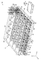
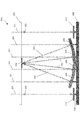
図1Aは、光から電力を生成するための集光モジュールの一実施例の斜視透視図である。集光モジュール10は集光アレイ12を含み、この集光アレイは、カバーガラス20、複数の光起電力電池22、基板24、及び複数の反射器、又は集光器30を備えている。集光モジュール10は制御モジュール32も含む。
FIG. 1A is a perspective perspective view of one embodiment of a light collection module for generating power from light. The
図1Aに示すように、光起電力電池22は、カバーガラス20において5×5のアレイに構成され、その結果集光アレイ12内部には合計25の光起電力電池22が含まれる。しかしながら、当業者であれば、集光アレイ12が任意の数の光起電力電池22を含み得ることを理解するであろう。反射器30は、各々が対応する光起電力電池22に関連付けられた反射器群40に配置することができる。反射器群40内部に含まれる各反射器30は、光源(図示しない)によって光起電力電池22上に生じる複数の光ビーム42を集束又は反射させるために、関連付けられた光起電力電池22に対して配置することができる。
As shown in FIG. 1A, the
光源は、例えば、建造物の人工的照明、レーザ、又は太陽といった任意の種類の放射エネルギー源でよい。各反射器30は、光源の位置が変化すると、関連付けられた反射器群40内部に位置する各反射器30がそれに応じて傾斜し、関連付けられた光起電力電池22に対して変化した光源の位置を追跡するように、選択的に傾斜角を変更することができる。光起電力電池に向かって光を方向付けるように配向された反射器は、光起電力電池励起位置にある。光起電力電池励起位置は、変更及び連続的に更新可能である。例えば、光源が太陽である場合、関連付けられた反射器群40の内部に位置する各反射器30は、一日を通して変化する太陽の位置を追跡するように、それに応じて傾斜角を変更することができる。光起電力電池から光を逸らすように配向された反射器は、光起電力電池非励起位置にある。
The light source may be any type of radiant energy source, for example, artificial lighting of buildings, lasers, or the sun. Each
集光モジュール10は、光エネルギーが電気エネルギーに変換される任意の用途で使用され得る。本明細書に記載される実施態様の実施例は、主として太陽電力変換用途における集光モジュールの使用に関する。図1Aは、例えば、スリムラインポケットサイズポータブル発電機のような、比較的小型の用途において使用される単一の集光モジュール10を示している。しかしながら、単一の集光モジュール10は、大規模な太陽発電機において使用される複数の集光モジュールの二次元又はタイル式のアレイ(図示しない)を形成するために、他の集光モジュールに電気接続されるか又は他の集光モジュールと群化される。このような太陽発電機は、例えば、地上ポータブル発電機、無人航空機(UAV)、又は衛星といった用途に使用され得る。
The
カバーガラス20は、光ビーム42が、例えば、ガラス、プラスチック、又は二酸化ケイ素を通過することを可能にする任意の透明材料から構築され得る。基板24は、反射器30を支持又は搭載するために使用され得る。一つの非限定的態様では、基板24は融合シリカから構成される。
制御モジュール32は、集光モジュール10の制御及びテレメトリ機能を提供する。制御モジュール32は、プロセッサのような処理リソースと、プログラムされた機能を実施するためのデータ及び命令を記憶する記憶能とを含むことができる。制御モジュール32は、以下に詳述するような、反射器30の位置及び方向を制御するための機能を含む。例示的実装態様では、制御モジュール32は、対応する光起電力電池22に向かって光を方向付ける反射器30又は反射器群40の数を制御することができ、ここで、そのように制御される反射器群40の数は、集光アレイ12上の反射器群40の総数の集光比である。制御モジュール32は、例えば、スペースクラフト上のフライトコンピュータといった他のコンピューティングコンポーネントから信号又は命令を受信するための通信インターフェースも含むことができる。
The control module 32 provides control and telemetry functions for the
図1B〜7を参照して以下に記載される例示的実装態様において、太陽電源、特にスペースクラフトに使用される太陽電源の観点から集光モジュール10の実施例が記載される。本発明が、特定の用途又は使用、或いは装置又は方法の詳細な形態に限定されないことを理解されたい。加えて、以下の集光アレイの記載は、太陽電池としての光起電力電池に言及している。用語「光起電力電池」及び「太陽電池」は互換可能に使用され得る。
In the exemplary implementation described below with reference to FIGS. 1B-7, an example of a
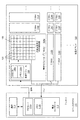
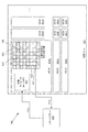
図1Bは、スペースクラフト110に電力を提供する太陽電源100の一実施例の概略図である。太陽光集光システム100は、ソーラーウィングと呼ばれる平坦な二次元パネルを形成するように構成された複数の集光モジュール104a−iを備える。集光モジュール104a−iの各々は、各集光モジュール104a−i内の太陽光集光アレイ108から電力出力を生成する。各集光モジュール104a−iの電力出力は、集光アレイの電力出力Voutを提供するように接続され、この電力出力はスペースクラフト110に電力を提供するために使用される。
FIG. 1B is a schematic diagram of one embodiment of a solar power supply 100 that provides power to the
スペースクラフト110は、電力コントローラ112、及び通信モジュール116を含む。電力コントローラ112は、集光アレイの電力出力(Voutで)に接続され、太陽電源100からの電力をスペースクラフト110内の様々な負荷に分配するように構成されている。また、電力コントローラ112は、太陽電源100及びスペースクラフト110からデータを収集し、収集したデータを太陽電源100の制御に使用することができる。通信モジュール116は、地上制御システム(図示しない)と通信するための無線及びアンテナへの通信インターフェースを含む。電力コントローラ112は、太陽電源100の制御に関する機能を実行するためのプロセッサ114a及びメモリリソース114bを含むことができる。例えば、メモリリソース114bは、プロセッサ114aによって実行されると本明細書に記載される機能を実施するように動作する、実行可能な命令を記憶するための、非一過性のコンピュータ可読媒体を含む。このような機能には、集光比を決定するステップ、及び集光比に従って、反射器を太陽電池励起位置に位置させるように集光モジュール104a−iに信号送信するステップが含まれる。これらの機能及び他の機能について、以下に更に詳述する。
The
別の例示的実装態様では、電力コントローラ112は、処理及びメモリリソースに関してスペースクラフトのフライトコンピュータ(図示しない)と通信する。このような例示的実装態様では、フライトコンピュータは、電力コントローラ112によって提供されるテレメトリ信号を使用して、太陽電源100の総電力出力を制御するように集光モジュール104に信号送信又はコマンド送信する。フライトコンピュータも、集光モジュール104に対する信号通信及びコマンドを提供することができる。
In another exemplary implementation, the
電力制御機能の実施に使用されるプロセッサ114a及びメモリ114bは、本明細書では電力コントローラ112のコンポーネントとして記載される。このような記載は、記載される電力制御機能を実施するための処理リソースを、電力コントローラ112内の処理リソースに限定することを意図するものではない。上記のように、スペースクラフトはフライトコンピュータを含むことができ、これは、本明細書に記載される電力制御機能の一部又は全部を実施するために使用され得る。また、電力コントローラ112は、固有の処理リソース及びソフトウエアコンポーネントを備える独立したハードウエアコンポーネントとして、又はスペースクラフトのフライトコンピュータ内部に動作可能に接続又は統合された機能的コンポーネントとして動作することができる。
The
複数の集光モジュール104a−iは、構造的に統合されて、太陽電源100のソーラーウィング、又はパネルを形成し得る。複数の集光モジュール104a−iは、集光アレイの電力出力Voutに接続された電力出力を有し、これは、太陽電源100内の集光モジュール104a−iのすべての総電力出力である。図1Bの集光モジュール104aに示されるように、各集光モジュール104a−iは、制御モジュール106及び太陽光集光アレイ108を含む。
The plurality of concentrating
各集光モジュール104a−iは、図1Aを参照して上述したように構成される。集光アレイ108は、図1Bに集光アレイ108内の正方形として示される複数の太陽電池及び反射器群ユニット120を含む。各集光モジュール104a−i内の制御モジュール106はプロセッサ106aを含むことができ、これはASIC(特定用途向け集積回路)又はFPGA(フィールドプログラマブルゲートアレイ)として実装され得る。制御モジュール106はメモリ106bも含むことができ、これは、プロセッサによって実行されると集光モジュール104a−iの機能を実施するように動作する、実行可能な命令を記憶する非一過性のコンピュータ可読媒体を含む。このような機能は、例えば、太陽電池励起位置にある選択された数の反射器を集光比に従って制御することを含み得る。制御モジュール106は太陽電池及び反射器群ユニット120への制御インターフェースを含むことができ、これを通して反射器群の反射器の制御が実施される。
Each
太陽電源100の電力出力は、有利には、スペースクラフト110に電力供給するために最低限必要なレベルと、集光比により最大限利用可能な電力出力のレベルの間の所望の電力出力レベルを生成するように制御される。集光比は、図4及び5を参照する以下の記載に示すように、利用可能な電力出力とスペースクラフトの電力要件とを決定すること、及び集光アレイの電力出力が、過剰ではないがスペースクラフトの電力要件を満たすために十分であることを保証するように集光比を調整することにより、任意の時点で決定することができる。
The power output of the solar power source 100 advantageously has a desired power output level between the minimum required level for powering the
別の実施例では、集光比は、地上制御部から地上制御通信部を介して受け取られる設定点集光比として制御モジュール106に提供される。地上制御部は、ミッションの間のスペースクラフトの位置を追跡し、太陽電源により生成される電力が不十分又は過剰(太陽に対するスペースクラフトの方向に応じて)となる程度まで、スペースクラフトから太陽までの距離が太陽光強度に影響する時を決定する。地上制御部は、スペースクラフトから太陽までの距離に基づいて設定点集光比を決定し、設定点集光比をスペースクラフトに伝達する。スペースクラフトがミッションの間に太陽に対するその位置を追跡することができるのであれば、スペースクラフトが太陽に対するその位置に基づいて設定点集光比を決定してもよい。次いでスペースクラフトは、集光比を、スペースクラフトにより決定された設定点集光比に設定する。 In another embodiment, the concentration ratio is provided to the control module 106 as a set point concentration ratio received from the ground control unit via the ground control communication unit. The ground controller tracks the location of the spacecraft during the mission, from spacecraft to the sun, to the extent that the power generated by the solar power source is insufficient or excessive (depending on the direction of the spacecraft relative to the sun). Determine when the distance of the sun affects the sunlight intensity. The ground control unit determines the set point concentration ratio based on the distance from the spacecraft to the sun, and transmits the setpoint concentration ratio to the spacecraft. If the spacecraft is able to track its position relative to the sun during the mission, the spacecraft may determine the set point concentration ratio based on its position relative to the sun. The spacecraft then sets the concentration ratio to the set point concentration ratio determined by the spacecraft.
集光比は、太陽電池を励起するために使用される反射器又は集光器の総数の割合という意味に定義することができる。個々の反射器又は集光器を、太陽電池へと光を方向付ける太陽電池励起位置、又は太陽電池から光を逸らす太陽電池非励起位置に配置することができる。太陽電池は、励起されると、受け取った光の光強度に応じて電気エネルギーを生成する。太陽電池励起位置にある反射器の総数の集光比により、反射器の総数より少ない数の反射器により太陽電池のすべてが励起され、その結果電力出力が集光アレイ108の最大電力出力能より小さくなることが有りえる。
The concentration ratio can be defined in terms of the percentage of the total number of reflectors or collectors used to excite the solar cell. Individual reflectors or concentrators can be placed at solar cell excitation locations that direct light to the solar cells or solar cell non-excitation locations that divert light away from the solar cells. When the solar cell is excited, it generates electrical energy according to the light intensity of the received light. The collection ratio of the total number of reflectors in the solar cell excitation position causes all of the solar cells to be excited by a smaller number of reflectors than the total number of reflectors, so that the power output is greater than the maximum power output capability of the
別の実施例では、集光比は反射器群の集光比であり、含まれるすべての反射器が太陽電池励起位置にある、太陽電源100上の総数より少ない太陽電池又は対応する反射器群の数として定義される。残りの反射器群に含まれるすべての反射器は太陽電池非励起位置にある。別の実施例では、集光比は、太陽電源100上の集光アレイ108の総数より少ない集光アレイ108の数(すべての集光モジュール104a−iが同数の太陽電池を有する集光アレイ108を備えるとみなす)として定義される。
In another embodiment, the collection ratio is the collection ratio of the reflector group, and less than the total number of solar cells or corresponding reflector group on the solar power source 100, with all included reflectors in the solar cell excitation position. Defined as the number of. All the reflectors included in the remaining reflector groups are in the solar cell non-excitation position. In another embodiment, the light collection ratio is less than the total number of
また別の実施例では、集光比は面積の観点から定義され得る。太陽電源100は均等に分配された集光モジュール104a−iを備え、各集光モジュールは均等に分配された太陽電池及び反射器群120を有することで、太陽電池が太陽電源100上に均等に分配される。このような均等な分配を前提として、集光比は、太陽電源100を形成するパネルの総面積の一部分として定義することもできる。例えば、太陽光集光アレイ108は、30個の1平方インチの太陽電池を含む30平方インチの面積を有することができる。各太陽電池は、励起されると、総電力容量の1/30を提供する。集光比の1/2は、30平方インチの集光アレイ108の半分を指し、集光アレイ108の面積の半分に含まれる15個の太陽電池が励起され、他の15個の太陽電池は励起されない。
In yet another embodiment, the concentration ratio can be defined in terms of area. The solar power source 100 includes
太陽電源100の一実施例は、動作に1kWの電力を必要とするスペースクラフトのために、合計100個の太陽電池により最大電力容量25kWを生成する。集光比は電力出力の観点から指定することができ、集光比25:1が太陽電池励起位置に配向されたすべての反射器に対応する。集光比は、スペースクラフトが地球で又は地球の近くで動作するとき、初期集光比が電力容量の1/25となるように設定される。このような初期集光比を前提に、スペースクラフト110は、反射器の総数の1/25を太陽電池励起位置に置いて1kWの電力を生成するように、太陽電源を制御する。
One embodiment of the solar power supply 100 generates a maximum power capacity of 25 kW with a total of 100 solar cells for a spacecraft that requires 1 kW of power to operate. The concentration ratio can be specified in terms of power output, with a concentration ratio of 25: 1 corresponding to all reflectors oriented at the solar cell excitation location. The concentration ratio is set so that the initial concentration ratio is 1/25 of the power capacity when the spacecraft operates on or near the earth. On the premise of such an initial concentration ratio, the
集光比は、ミッションの間に、太陽電源100が、必要とされる電力出力を過剰にならないように生成することを保証するように修正される。例えば、最大25kWを生成する太陽電源を用い、動作に1kWの電力を必要とするスペースクラフトは、初期集光比1/25で地球(1AUの距離)から木星(5AUの距離)までのミッションを開始する。スペースクラフトが地球(及び太陽)から遠ざかるにつれ、光強度は低下し、その結果励起された太陽電池からの電力出力が減少する。したがって、スペースクラフトが地球から遠ざかるにつれ、集光比を増加させて電力を生成するために動員する太陽電池の数を増加させる。スペースクラフトが火星に到着するまでに、集光比は、スペースクラフトを動作させるために必要な1kWを生成するために利用可能な太陽電池をすべて励起する25:1となる。 The concentration ratio is modified to ensure that the solar power source 100 generates the required power output so as not to be excessive during the mission. For example, a spacecraft that uses a solar power source that generates up to 25 kW and requires 1 kW of power to operate a mission from the Earth (1 AU distance) to Jupiter (5 AU distance) with an initial concentration ratio of 1/25. Start. As the spacecraft moves away from the earth (and the sun), the light intensity decreases, resulting in a decrease in power output from the excited solar cell. Therefore, as the spacecraft moves away from the earth, it increases the concentration ratio and increases the number of solar cells that are mobilized to generate power. By the time the spacecraft arrives at Mars, the concentration ratio will be 25: 1 which excites all the solar cells available to produce the 1 kW needed to operate the spacecraft.
地球より太陽に近い目的地を有するスペースクラフトの太陽電源100も、集光比を用いて制御することができる。例えば、地球上で最大容量1kWの太陽光集光アレイにより電力供給されて金星へのミッションにあるスペースクラフトは、地球上ですべての太陽電池を励起してミッションを開始する。次いで、スペースクラフトが金星に接近するにつれて集光比を減少させる。したがって、スペースクラフトが金星に接近するにつれ、スペースクラフトに電力供給するために励起される太陽電池の数は減少する。 A spacecraft solar power source 100 having a destination closer to the sun than the Earth can also be controlled using the concentration ratio. For example, a spacecraft powered by a solar concentrator array with a maximum capacity of 1 kW on earth and in a mission to Venus will excite all solar cells on the earth and start the mission. The concentration ratio is then decreased as the spacecraft approaches Venus. Thus, as the spacecraft approaches Venus, the number of solar cells that are excited to power the spacecraft decreases.
上記のように、スペースクラフトが太陽に近付く又は太陽から遠ざかるにつれ太陽電源100の利用可能な電力出力が変化するため、集光比はミッションの間に変更される。例示的な一実装態様では、集光比は、プロセッサ114aによって決定され、各集光モジュール104a−iに対し、電力コントローラ112から各集光モジュール104a−iの各制御モジュール106への信号(図1Bの信号)により提供される。プロセッサ114aは、このようにして少なくとも一つの集光アレイに信号送信することができる。各集光モジュール104a−iは、太陽電池励起位置へと配向されるように選択される反射器の数を特定することにより集光比を適用し、ここで選択される反射器の数は、各集光モジュール104a−i内の反射器の総数のうちの反射器の集光比に相当する。
As described above, the concentrating ratio is changed during the mission, as the available power output of the solar power source 100 changes as the spacecraft approaches or moves away from the sun. In one exemplary implementation, the light collection ratio is determined by the
集光比は、反射器の総数のうち太陽電池励起位置へと配向する太陽光集光アレイ108内の反射器の数を計算するプロセッサ114aによって決定して使用することもできる。このとき、電力コントローラ112は、太陽電池励起位置に配向する反射器の数を各集光モジュール104a−iの各制御モジュール106に信号送信することができる。
The concentration ratio may also be determined and used by the
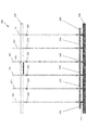
図2Aは、図1Bの集光アレイ108に使用され得る太陽電池及び反射器群ユニット200の一実施例の断面図である。図2Aの太陽電池及び反射器群ユニット200は、好ましくはガラス、又は図1Aを参照して上述したような他の適切な透明材料から作製された第1の平面基板202に搭載された太陽電池204を含む。対応する反射器群は、第1の平面基板202に平行で第1の平面基板から離間した第2の平面基板208に搭載された複数の反射器206を含み、よって太陽電池204は反射器群の反射器206に直接対向する。第1及び第2の基板202、208は、光201が第1の平面基板202の位置でパネルに入射するように配向される。光201は、図2Aにおいては第1の平面基板202に対して実質的に直角な入射角に方向付けられているが、図2Cを参照して後述するように、反射器206は、光201の入射角が直角から逸れる方向にシフトするとき、光を太陽電池204に向かうように維持するように調整することができる。光201は、反射器群の反射器206に向かって透明な第1の平面基板201を通過する。反射器206は、光205を、第1の平面基板202上の太陽電池204に戻るように方向付ける。
FIG. 2A is a cross-sectional view of one embodiment of a solar cell and
本明細書に記載される例示的実装態様では、太陽電池204は、光を受け取って光強度を示す電気信号を生成する任意の適切な電子コンポーネントでよい。対応する反射器206は、光を反射させて太陽電池204に戻すように構成されたミラーを備える。例示的実装態様では、反射器206は、小型ミラー及び集光アレイ上の太陽電池及び反射器群ユニット200の密度を上昇させる制御コンポーネントを取り込んだ微小電気機械システム(MEMS)のコンポーネントとして実装される。各反射器206は、一又は複数の次元でミラーを回転させることにより反射器206を配向するように構成されたアクチュエータ210により制御することができる。アクチュエータ210は、反射器を太陽電池204に近づける又は太陽電池から遠ざけることにより併進配向を提供することもできる。アクチュエータ210は、制御モジュール106から、制御モジュール106によるコマンドに従って反射器206を移動させる信号を受信することができる。
In the exemplary implementation described herein,
各反射器の配向を制御することにより、制御モジュール106は、反射器に対応する太陽電池に方向付けられる光強度を制御することができる。例えば、制御モジュール106は、反射器群の各反射器206に対し、図2Aに示されるように光205を太陽電池204へと方向付ける信号を送信することができる。図2Aに示される各反射器206のこのような位置は、太陽電池励起位置と呼ばれ、これは、反射器206が光を太陽電池204へと方向付けることを可能にする反射器206の位置又は配向である。
By controlling the orientation of each reflector, the control module 106 can control the light intensity directed to the solar cell corresponding to the reflector. For example, the control module 106 can send a signal that directs the light 205 to the
図2Bは、太陽電池、及び太陽電池非励起位置に配向された反射器206を含む反射器群ユニット200の断面図である。制御モジュール106は、アクチュエータ210に対し、光203が太陽電池204から逸れるように反射器206を配向する信号を送信することができる。反射器206が、光203を、光203が太陽電池204を励起しないように方向付けるとき、太陽電池204は電気信号を生成せず、集光モジュール104a(図1B)の電力出力に寄与しない。図2Bに示される反射器206は、光201の入射角に沿って光を戻すように配向されている。しかしながら、太陽電池非励起位置は、反射器206が光を太陽電池204に向かわないいずれかの方向に方向付けることを可能にする、反射器206のどのような位置又は配向でもよい。
FIG. 2B is a cross-sectional view of a
上述のように、集光比は、すべての反射器が太陽電池励起位置にある反射器群の総数より少ない反射器群の数と定義することができる。図2A及び2Bは、このように定義された集光比が、集光アレイ108の電力出力を制御するためにどのように使用されるかを示している。図2Aに示すように、各太陽電池及び反射器群ユニット120内の反射器206のすべてが太陽電池励起位置に配向されている場合、各太陽電池204は、入射光強度に対応して実質的に最大の電気出力を生成している。図2Bに示すように、各太陽電池及び反射器群120内の反射器206のすべてが太陽電池非励起位置に配向されている場合、対応する各太陽電池204から出力される電力は実質的にゼロである。集光比を増加させることにより、すべての反射器が太陽電池励起位置にある反射器群の数が増加する結果、電力出力が高まる。集光比を減少させることにより、すべての反射器が非太陽電池励起位置にある反射器群の数が増加する結果、電力出力が低下する。
As described above, the light collection ratio can be defined as the number of reflector groups that is less than the total number of reflector groups in which all reflectors are in the solar cell excitation position. 2A and 2B illustrate how the concentration ratio thus defined is used to control the power output of the
太陽電池励起位置は、スペースクラフト110の動作の間に変動し得る。上述のように、太陽電源100のカバーパネル上における光の入射角は、実質的に90°から変動し得る。スペースクラフト110は、スペースクラフト110が宇宙を移動するときに入射角を実質的に90°に維持するために太陽電源100の配向及び位置を制御するハードウエア及びソフトウエアコンポーネントを含み得る。スペースクラフト110が、太陽電源100上に90°の光入射角を維持することは常に可能でない。実質的に90°の光入射角が維持できない場合、太陽電池204を励起する反射器群の反射器206は、励起される太陽電池204上に最大強度を維持するように調整され得る。実際には、反射器206の太陽電池励起位置は、太陽電源100の配向の変化に応じて修正される。
The solar cell excitation position may vary during operation of the
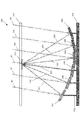
図2Cは、光201が太陽電源100(図1B)に直角でないときの、太陽電池204及び太陽電池励起位置にある対応する反射器206の断面図である。図2Cに示される実施例における光201の入射角は、図2A及び2Bの実施例に示される光201の入射角とは異なり、実質的に90°ではない。入射角が直角から逸れるにつれ、制御モジュール106(図1B)は、光205を太陽電池204へと方向付け続けるように反射器206を配置する信号をアクチュエータ210に送信することにより、反射器206を制御する。したがって、反射器206の太陽電池励起位置は、反射器及び光201の入射角に応じて変動する。
2C is a cross-sectional view of the
上述のように、集光比は、集光アレイ内又は太陽電源内の反射器の総数と定義してもよい。これにより、集光比は、反射器群内の反射器の数に適用される。図2Dは、選択された反射器206が太陽電池励起位置にあり、他の反射器212が太陽電池非励起位置にある、太陽電池204及び対応する反射器の一実施例の断面図である。太陽電池励起位置へと配向される選択された数の反射器206が反射器群の反射器のすべてより少ないとき、太陽電池204は最大量未満の電力を生成する。図2Dに示すように、反射器群内のいくつかの反射器206は太陽電池励起位置に、同じ反射器群内の他の反射器212は太陽電池非励起位置に配置される。集光アレイ内で太陽電池励起位置に配置される選択された反射器206の総数は、集光アレイにおける反射器の総数の集光比に相当する。
As mentioned above, the light collection ratio may be defined as the total number of reflectors in the light collection array or in the solar power source. Thereby, the light collection ratio is applied to the number of reflectors in the reflector group. FIG. 2D is a cross-sectional view of one embodiment of the
有利には、集光アレイ108の電力出力を制御するために集光比を使用することにより、スペースクラフトの電力要件が過剰な電力レベルを生じさせずに満たされることが保証される。地球から木星へと移動する、1kWの電力を必要とするスペースクラフトは、初期集光比を、1kWの電力を生成するために十分な最大集光比未満に設定し、木星の近くで同じ1kWの電力を生成するために、最大集光比に達するまで集光比を増加させて。同様に、地球から金星へと移動する、1kWの電力を必要とするスペースクラフトは、初期集光比を、1kWの電力を生成するために十分な最大集光比に設定し、金星で同じ1kWの電力を生成するために必要な最小集光比に達するまで集光比を減少させる。
Advantageously, the use of the collection ratio to control the power output of the
図3〜5は、集光比を用いて集光アレイの電力出力を制御するための方法を示すフローチャートである。図3〜5に示される方法では、集光比が利用可能な電力出力とスペースクラフトの電力要件とに基づくことが前提であることに注意されたい。上述のように、集光比は、限定しないが、太陽までの距離といった他の方法を使用して決定することもできる。図3〜5の方法の以下の記載では、特に別途断らない限り、図1Bに示されるコンポーネントに言及する。図3〜5の方法は、制御モジュール106又はスペースクラフト110上の別のコンピューティングデバイスに、メモリに記憶されてプロセッサにより実行されるコンピュータ実施命令を含むソフトウエアコンポーネントとして実装され得る。
3-5 are flowcharts illustrating a method for controlling the power output of a light collection array using a light collection ratio. Note that in the methods shown in FIGS. 3-5, it is assumed that the concentration ratio is based on available power output and spacecraft power requirements. As described above, the light collection ratio can be determined using other methods such as, but not limited to, the distance to the sun. In the following description of the method of FIGS. 3-5, reference will be made to the components shown in FIG. 1B unless otherwise noted. The method of FIGS. 3-5 may be implemented as a software component that includes computer-implemented instructions stored in memory and executed by a processor on another computing device on control module 106 or
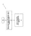
図3は、集光アレイ108からの電力出力を制御するための第1の例示的方法300の動作を示すフローチャートである。図1Bに示される非限定的実施例の実装態様では、電力コントローラ112が、集光比を決定し、集光比に関する情報(又は集光比そのもの)を制御モジュール106に伝達する。ステップ302において、制御モジュール106は、選択された数の反射器を太陽電池励起位置に配置する信号又はコマンドを受け取る。ここで、選択された反射器の数は、集光アレイ108上における反射器の集光比である。
FIG. 3 is a flowchart illustrating the operation of a first
ステップ304では、制御モジュール106は、集光アレイ108上の選択された数の反射器を、集光アレイ108から電力出力を生成する太陽電池励起位置に配置する。制御モジュール106は、選択された数の反射器に対応するアクチュエータに信号送信することにより、反射器を配置する。
In
上述のように、集光比は、有利には、太陽から遠ざかるスペースクラフトについて、及び太陽に向かうスペースクラフトについて、調整することができる。図4は、太陽から遠ざかるスペースクラフトのために集光比を変化させる方法400の一実施例の動作を示すフローチャートである。図4の方法400は、各集光モジュール104a−iの制御モジュール106に信号送信する集光比を決定するために、電力コントローラ112によって実施される。別の実施例では、太陽電源100は、電力コントローラ112について本明細書に記載される動作を実施する制御モジュール106を有する単一の集光モジュール104a−iを用いて実現される。
As mentioned above, the light collection ratio can advantageously be adjusted for spacecraft moving away from the sun and for spacecraft heading to the sun. FIG. 4 is a flowchart illustrating the operation of one embodiment of a
ステップ402では、最大集光比より小さい初期集光比が決定される。電力要件が1kWであり、総最大電力出力容量が25kWであるスペースクラフトが木星に向かう上記実施例では、実質的に地球上にいる間に必要な1kWを生成するために、初期集光比は1/25に設定される。1/25に対応する数の反射器群が選択されて、太陽電池励起位置に配向される。ステップ404では、電力コントローラ112は、スペースクラフトの電力要件を決定するためにバス電力負荷を評価する。ステップ406では、集光アレイ108、又はアレイ群からの利用可能な電力出力が測定される。上述のように、利用可能な電力出力は、光強度の低下に起因して、スペースクラフトが太陽から遠ざかるにつれて低下する。
In
判定ブロック408において、利用可能な電力出力がスペースクラフトの電力要件と比較される。利用可能な電力出力がスペースクラフトの電力要件より大きい場合(YES)、集光比は変更されない。利用可能な電力出力がスペースクラフトの電力要件より小さい場合(NO)、集光比はステップ410で増加させることができる。利用可能な電力がスペースクラフトの電力要件+閾値に維持されるべきである場合、閾値を適用してもよいことに注意されたい。
At
方法400における制御は、両判定ブロック408及びステップ410から、スペースクラフトの電力要件を連続的に監視するステップ404へ、次いで利用可能な電力出力を連続的に監視するステップ406へと進行する。
Control in
図5は、太陽に向かうスペースクラフトのために集光比を変化させる方法500の一実施例の動作を示すフローチャートである。図5の方法500は、各集光モジュール104a−iの制御モジュール106に信号送信する集光比を決定するために、電力コントローラ112によって実施される。別の実施例では、太陽電源100は、電力コントローラ112について本明細書に記載される動作を実施する制御モジュール106を有する単一の集光モジュール104a−iを用いて実現される。
FIG. 5 is a flowchart illustrating the operation of an embodiment of a
ステップ502では、初期位置において最小集光比より大きい初期集光比が決定される。電力要件が1kWであり、総最大電力出力容量が1kWであるスペースクラフトが金星に向かう上記実施例では、実質的に初期位置(地球)上にいる間に必要な1kWを生成するために、初期集光比は10/1に設定される。10:1に対応する数の反射器群、又は反射器群のすべてが選択されて、太陽電池励起位置に配向される。ステップ504では、電力コントローラ112は、集光アレイ108に要求される電力を決定するためにバス電力負荷を評価する。ステップ506では、集光アレイ108、又はアレイ群からの利用可能な電力が測定される。上述のように、電力出力は、スペースクラフト110が太陽に接近するにつれて上昇する光強度に起因して、スペースクラフトが太陽に向かって移動するにつれて増加する。
In step 502, an initial light collection ratio greater than the minimum light collection ratio at the initial position is determined. In the above example where a spacecraft with a power requirement of 1 kW and a total maximum power output capacity of 1 kW towards Venus, in order to generate the required 1 kW while essentially on the initial position (Earth) The concentration ratio is set to 10/1. The number of reflector groups corresponding to 10: 1, or all of the reflector groups, is selected and oriented at the solar cell excitation location. In
判定ブロック508において、利用可能な電力出力はスペースクラフトの電力要件と比較される。利用可能な電力出力がスペースクラフトの電力要件+閾値より小さい場合(NO)、集光比は変更されない。利用可能な電力がスペースクラフトの電力要件+閾値を上回る場合(YES)、集光比はステップ510で減少させることができる。閾値は、過剰とみなされる電力レベルを示す適切な値とすることができる。
At
方法500における制御は、両判定ブロック508及びステップ510から、スペースクラフトの電力要件を連続的に監視するステップ504へ、次いで利用可能な電力出力を連続的に監視するステップ506へと進行する。
Control in
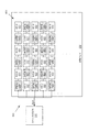
上述のように、集光比は、選択された数の反射器に対して個々に、又は反射器群内に適用することができる。図6Aは、太陽電源602によって電力供給されるスペースクラフト610を含む例示的な太陽駆動宇宙システム600のブロック図であり、集光比に従う反射器群の励起を示している。太陽電源602は、複数のマイクロ集光モジュール(「MCM」)604a−iを備え、各MCM604a−iは制御モジュール606とマイクロ集光アレイ608を含んでいる。図6Aのマイクロ集光アレイ608は、太陽電池と対応するMEMS反射器群とを含む。MCM604a−iは、図1A及び1Bを参照して上述した集光モジュール10及び104a−iの例である。マイクロ集光アレイ608は、図1A及び1Bを参照して上述した集光アレイ12及び108の例である。
As described above, the light collection ratio can be applied to a selected number of reflectors individually or within a reflector group. FIG. 6A is a block diagram of an exemplary solar
図6Aのマイクロ集光アレイ604aの制御モジュール606は、図3を参照して上述した方法300を実施することができる。集光比に従う数の反射器が、反射器群において選択される。このように、選択された反射器の数は、太陽電池の数である反射器群の総数の集光比である。選択された数の反射器群の各々に含まれる反射器のすべては、図2Aに示される太陽電池励起位置に配向される。図6Aは、第1組の反射器群620に対応する太陽電池を励起するように選択されていない反射器群として、第1組の反射器群620を示している。図6Aにおいてグレイの四角で示されている第2組の反射器群622は、第2組の反射器群622の各々に対応する太陽電池を励起するように選択された集光比1/2に対応する選択された数の反射器群である。図6Aの実施例は、各太陽電池の最大電力を出力するように励起する太陽電池の集光比の選択を示している。マイクロ集光アレイ604aの総電力出力は、マイクロ集光アレイ604aの総電力出力容量の集光比である。
The
図6Bは、太陽アレイ652を用いてスペースクラフト610に電力供給するための例示的宇宙システムのブロック図である。太陽アレイ652は、複数のマイクロ集光モジュール660及び662を含み、各マイクロ集光モジュール660及び662は、図6AのMCM604a−iとして構成されている。図6Bに示される実施例では、スペースクラフト610は、集光比を決定し、集光比に対応するMCM658の数を選択し、次いで選択されたMCM658上の反射器群のすべてを励起して太陽電池励起位置に配向する。図6Bは太陽アレイ652を示し、図中グレイの四角として示す第1組のMCM660は、MCM658の最大電力出力容量を生成するために選択されたMCM660を表している。第1組のMCM660では、各MCM660の各マイクロ集光アレイ608(図6A)内の各太陽電池に対応する各反射器群が、太陽電池励起位置、例えば図2Aの反射器206の配向に配向されている。白い四角で示される第2組のMCM662は、発電するように選択されていないMCM662を表している。第2組のMCM660では、各MCM662の各マイクロ集光アレイ608(図6A)内の各太陽電池に対応する各反射器群が、太陽電池非励起位置、例えば図2Bの反射器206の配向に配向されている。
FIG. 6B is a block diagram of an exemplary space system for powering
図7は、ミッションの間に集光比が変更される太陽光集光アレイ104a−iを有する図1Bの太陽電源100の例示的一実装態様の電力出力と、集光比の変更を実施しない太陽光集光アレイを有する一般的な太陽電池の電力出力との比較を示すグラフ700である。図7のグラフ700は二つの垂直軸を有している。右側の垂直軸(「アレイ電力」)は、値1がスペースクラフトの電力要件を表し、値20がスペースクラフトの電力要件の20倍を表すように正規化された電力出力を表す。左側の垂直軸(「集光」)は、図1Bの太陽電源100の例示的実装態様により使用され得る集光比の値を表す。
FIG. 7 illustrates the power output of one exemplary implementation of the solar power supply 100 of FIG. 1B with the
グラフ700は、一般的な太陽電源の電力出力を表す第1の曲線702を示す。第1の曲線702は、右側の垂直軸(「アレイ電力」)を用いて、太陽までの距離が増すにつれて下降する電力出力を示している。第1の曲線702によって示される電力出力は、ペースクラフトの電力要件の約25倍である(地球での)1AUにおける電力出力から、太陽からの木星の距離5AUにおける電力出力約1まで下降する。電力出力の低下は、スペースクラフトが太陽から遠ざかるにつれて光強度が低下することに起因する。
The
図7は、集光モジュール104a−iの集光比を変化させる図1Bの太陽電源100の例示的実装態様の電力出力を表す第2の曲線704を示している。第2の曲線704も、右側の垂直軸(「アレイ電力」)を用いて、スペースクラフトが太陽から遠ざかっても、ミッションの過程を通して実質的に一定である電力出力を示している。
FIG. 7 shows a
図7は、第3の曲線706において、太陽電源100の例示的実装態様の集光比と電力出力の関係を示している。第3の曲線706は、左側の垂直軸(「集光」)を用いて、スペースクラフトが太陽から遠ざかるにつれて、電力出力を第2の曲線704に示されるように一定に維持するために、集光比が増加することを示している。上述のように、ミッション開始時に小さい集光比は、各MCM内部の反射器の一部は太陽電池励起位置に、残りの反射器を太陽電池非励起位置に配向する。第3の曲線706により示されるように、スペースクラフトが太陽から遠ざかるにつれて集光比は増加する。集光比の増加により、約5A.Uにおいて反射器のすべてが太陽電池励起位置に位置するまで、ミッションの間に太陽電池励起位置に配向される反射器の数が次第に増す。電力出力は、ミッションの過程を通して実質的に一定である。
FIG. 7 shows the relationship between the light collection ratio and the power output of an exemplary implementation of the solar power supply 100 in the
電気エネルギーを生成するために光起電力電池に光を集束させる集光器を用いて集光アレイの電力出力を制御するためのシステム及び方法の例示的実装態様。反射器群の個々の反射器が、電力分配の管理に関係のない機能のために太陽電池非励起位置に配向されてもよいことに注意されたい。例えば、スペースクラフトは、スペースクラフトに損傷を生じさせるのに十分な光エネルギーに突発的に曝されることがある。このような曝露は、スペースクラフトの破壊を目的とするエンティティによるレーザ攻撃、又は自然発生源若しくは他の非自然発生源からの高強度の発光に起因して起こりうる。 An exemplary implementation of a system and method for controlling the power output of a concentrating array using a concentrator that focuses light onto a photovoltaic cell to generate electrical energy. Note that the individual reflectors of the reflector group may be oriented at solar cell non-excitation locations for functions not related to the management of power distribution. For example, a spacecraft may be suddenly exposed to sufficient light energy to cause damage to the spacecraft. Such exposure can occur due to laser attacks by entities aimed at destroying the spacecraft, or high intensity emission from natural or other non-natural sources.
突発的な破壊的光エネルギーは、スペースクラフトにより検出され得る。例えば、ミッションの間に、電力コントローラ112は利用可能な電力出力を連続的に監視する。利用可能な電力出力の監視中、電力コントローラ112は、集光アレイ108上への太陽光の入射により生じたとは思われないスパイク又は突然の電力サージを感知することがある。電力コントローラ112は、スパイク又は突然の電力サージから、スペースクラフトが損傷を生じるのに十分な突発的光エネルギーによる攻撃を受けていると決定することができる。これに応答して、集光アレイ108は、スペースクラフトから逸れるようにレーザ光を方向付けるために、選択された数の反射器群を太陽電池非励起位置に配向するように制御することができる。選択数は、スペースクラフトへの電力が遮断される、反射器群のすべてとしてもよく、又はレーザのエネルギーをスペースクラフトから逸らすために十分な数としてもよい。このような応答は、制御プログラミングに自律的にプログラムすることができるか、又は既知の脅威に先立ち地上から命令することができる。
Sudden destructive light energy can be detected by spacecraft. For example, during a mission, the
複数の光起電力電池と、複数の光起電力電池に対応する反射器の群に配置された複数の反射器とを備える集光アレイの電力出力を制御するための例示的方法が上記に記載され、この方法は、
集光アレイ上の、複数の反射器の集光比である選択された数の反射器を、集光アレイから電力出力を生成する光起電力電池励起位置に配置する信号を受け取ること、及び
選択された数の反射器を、集光アレイから電力出力を生成する光起電力電池励起位置に配置すること
を含む。
An exemplary method for controlling the power output of a concentrating array comprising a plurality of photovoltaic cells and a plurality of reflectors arranged in a group of reflectors corresponding to the plurality of photovoltaic cells is described above. And this method is
Receiving a signal to place a selected number of reflectors on a condensing array at a photovoltaic cell excitation location that produces a power output from the condensing array; and selecting Placing a number of reflectors at a photovoltaic cell excitation location that produces a power output from the collection array.
この例示的方法の一態様では、各反射器は、アクチュエータに連結された小型ミラーを有する微小電気機械システム(MEMS)デバイスであり、選択された数の反射器の各反射器を調整するステップは、アクチュエータに対し、小型ミラーが対応する光起電力電池に向かって光を反射するように小型ミラーを配置するように信号伝達する。 In one aspect of this exemplary method, each reflector is a microelectromechanical system (MEMS) device having a miniature mirror coupled to an actuator, and the step of adjusting each reflector of a selected number of reflectors includes The signal is transmitted to the actuator so that the small mirror is arranged so that the small mirror reflects light toward the corresponding photovoltaic cell.
この例示的方法の更なる態様では、反射器群内で、選択された数の反射器が選択され、選択された数の反射器を含む反射器群の数は反射器群の集光比に対応し、したがって、選択された数の反射器を配置するステップは、選択された数の反射器を、集光比に対応する数の光起電力電池を励起する反射器群として配置することを含む。 In a further aspect of this exemplary method, a selected number of reflectors are selected within the reflector group, and the number of reflector groups including the selected number of reflectors is a reflection ratio of the reflector group. Therefore, the step of arranging the selected number of reflectors is to arrange the selected number of reflectors as a group of reflectors that excite the number of photovoltaic cells corresponding to the collection ratio. Including.
太陽電源の一実施例が上記に記載され、この太陽電源は、
複数の太陽電池と、各群が太陽電池の一つに対応する複数の群の反射器とを備える集光アレイ、
各太陽電池に接続されて、光が反射器から太陽電池に反射されるとき、各太陽電池により生成される電力を受け取る電力出力部、
プロセッサと、非一過性のコンピュータ可読記憶媒体とを有する制御モジュールであって、記憶媒体は、プロセッサによって実行されると、
集光アレイ上の、複数の反射器の集光比である選択された数の反射器を、集光アレイから電力出力を生成する太陽電池励起位置に配置する信号を受け取り;
選択された数の反射器を、集光アレイから電力出力を生成する太陽電池励起位置に配置する
ように動作する、実行可能な命令を記憶する、制御モジュール
を備える。
One example of a solar power source is described above, and this solar power source is
A light collection array comprising a plurality of solar cells and a plurality of groups of reflectors, each group corresponding to one of the solar cells;
A power output connected to each solar cell and receiving power generated by each solar cell when light is reflected from the reflector to the solar cell;
A control module having a processor and a non-transitory computer readable storage medium, the storage medium being executed by the processor;
Receiving a signal that places a selected number of reflectors on the concentrator array at a solar cell excitation location that produces a power output from the concentrator array;
A control module is provided that stores executable instructions that operate to place a selected number of reflectors at solar cell excitation locations that generate power output from the light collection array.
この例示的太陽電源の態様では、非一過性のコンピュータ可読記憶媒体は、プロセッサによって実行されると、集光比に対応する数の太陽電池を励起する反射器群として、選択された数の反射器を配置するように更に動作する、実行可能な命令を記憶する。 In this exemplary solar power source aspect, a non-transitory computer readable storage medium is selected by a selected number of reflector groups that, when executed by a processor, excite a number of solar cells corresponding to a concentration ratio. Stores executable instructions that further operate to position the reflector.
スペースクラフトの実施例が上記に記載される。スペースクラフトは、
複数の太陽電池と、各反射器群が太陽電池の一つに対応する複数の反射器群とを含み、複数の太陽電池が、集光アレイの電力出力を生成するように構成されている少なくとも一つの集光アレイ、
少なくとも一つの集光アレイの各々に接続されて、光が反射器から太陽電池に反射されるとき、太陽電池により生成される集光アレイの電力出力を受け取る電力出力部、並びに
電力出力を受け取り、少なくとも一つの集光アレイからの集光アレイの電力出力をスペースクラフトに分配するように接続された電力コントローラであって、プロセッサ及び非一過性のコンピュータ可読記憶媒体を含み、記憶媒体が、プロセッサによって実行されると、
少なくとも一つの集光アレイの集光比を決定し、
少なくとも一つの集光アレイに対し、集光比に基づく選択された数の反射器を、対応する少なくとも一つの集光アレイから電力出力を生成する太陽電池励起位置に配置する信号を送信する
ように動作する、実行可能な命令を記憶する、電力コントローラ
を備える。
Examples of spacecraft are described above. Spacecraft
A plurality of solar cells, each reflector group including a plurality of reflector groups corresponding to one of the solar cells, wherein the plurality of solar cells are configured to generate a power output of the concentrating array; One condensing array,
A power output connected to each of the at least one concentrating array and receiving a power output of the concentrating array generated by the solar cell when light is reflected from the reflector to the solar cell; A power controller connected to distribute a power output of a light collection array from at least one light collection array to a spacecraft, the processor comprising a processor and a non-transitory computer readable storage medium, the storage medium comprising: When executed by
Determining the concentration ratio of at least one condensing array;
For at least one concentrator array, to send a signal to place a selected number of reflectors based on the concentrator ratio at a solar cell excitation location that generates a power output from the corresponding at least one concentrator array A power controller is provided that stores executable instructions that operate.
一態様では、スペースクラフトは、地上制御部と通信するための通信モジュールを更に備える。 In one aspect, the spacecraft further comprises a communication module for communicating with the ground control unit.
スペースクラフトの別の態様では、電力コントローラにおいて、非一過性のコンピュータ可読記憶媒体は、プロセッサによって実行されると、
地上制御部から通信モジュールを介して設定点集光比を受信し、
集光比の決定において、地上制御部から受信した設定点集光比に集光比を設定する
ように更に動作する、実行可能な命令を記憶する。
In another aspect of the spacecraft, in the power controller, the non-transitory computer readable storage medium is executed by a processor,
Receive the set point concentration ratio from the ground control unit via the communication module,
In determining the concentration ratio, an executable instruction is stored that further operates to set the concentration ratio to the setpoint concentration ratio received from the ground controller.
スペースクラフトの別の態様では、電力コントローラにおいて、非一過性のコンピュータ可読記憶媒体は、プロセッサによって実行されると、
太陽に対するスペースクラフトの位置を受信し、
スペースクラフトが太陽から遠ざかるにつれて、集光比を決定するステップにおいて集光比を増加させる
ように更に動作する、実行可能な命令を記憶する。
In another aspect of the spacecraft, in the power controller, the non-transitory computer readable storage medium is executed by a processor,
Receive the position of the spacecraft relative to the sun,
As the spacecraft moves away from the sun, it stores executable instructions that further operate to increase the concentration ratio in the step of determining the concentration ratio.
スペースクラフトの別の態様では、電力コントローラにおいて、非一過性のコンピュータ可読記憶媒体は、プロセッサによって実行されると、
太陽に対するスペースクラフトの位置を受信し、
スペースクラフトが太陽に近付くにつれて、集光比を決定するステップにおいて集光比を減少させる
ように更に動作する、実行可能な命令を記憶する。
In another aspect of the spacecraft, in the power controller, the non-transitory computer readable storage medium is executed by a processor,
Receive the position of the spacecraft relative to the sun,
As the spacecraft approaches the sun, it stores executable instructions that further operate to reduce the concentration ratio in the step of determining the concentration ratio.
スペースクラフトの別の態様では、電力コントローラにおいて、非一過性のコンピュータ可読記憶媒体は、プロセッサによって実行されると、
利用可能な電力出力を測定し、
スペースクラフトの電力要件を測定し、
利用可能な電力出力とスペースクラフトの電力要件との差異を決定し、
集光比を決定するステップにおいて、集光比を、利用可能な電力出力とスペースクラフトの電力要件との差異に基づかせる
ように更に動作する、実行可能な命令を記憶する。
In another aspect of the spacecraft, in the power controller, the non-transitory computer readable storage medium is executed by a processor,
Measure the available power output,
Measure spacecraft power requirements,
Determine the difference between available power output and spacecraft power requirements,
In the step of determining the concentration ratio, executable instructions are stored that further operate to base the concentration ratio on the difference between the available power output and the spacecraft power requirements.
別の態様では、スペースクラフトは、
複数の集光アレイ
を更に備え、
電力コントローラにおいて、非一過性のコンピュータ可読記憶媒体は、プロセッサによって実行されると、
少なくとも一つの集光アレイに対する信号送信において、
複数の集光アレイのうちの第1の選択された複数に対し、第1の選択された複数の集光アレイの各々の反射器のすべてを、太陽電池励起位置に配置する信号を送信し、
複数の集光アレイのうちの第2の選択された複数に対し、第2の選択された複数の集光アレイの各々の反射器のすべてを、太陽電池非励起位置に配置する信号を送信する
ように更に動作する、実行可能な命令を記憶し、
ここで第1の選択された複数の集光アレイに含まれる集光アレイの数は、集光比に対応する。
In another aspect, the spacecraft is
A plurality of condensing arrays;
In the power controller, when the non-transitory computer readable storage medium is executed by a processor,
In signal transmission to at least one collection array,
Transmitting a signal for placing all of the reflectors of each of the first selected plurality of condensing arrays at a solar cell excitation location to a first selected plurality of the plurality of concentrating arrays;
A signal for placing all of the reflectors of each of the second selected plurality of condensing arrays at a solar cell non-excitation position is transmitted to a second selected plurality of the plurality of concentrating arrays. Store executable instructions, which further operate as
Here, the number of the light collecting arrays included in the plurality of first selected light collecting arrays corresponds to the light collecting ratio.
少なくとも一つの集光モジュールによりスペースクラフトのための発電を行うための例示的方法が記載される。各集光モジュールは、複数の太陽電池と、複数の太陽電池に対応する、反射器群に配置される複数の反射器とを有する集光アレイを備える。方法は、
少なくとも一つの集光アレイの集光比を決定すること、
少なくとも一つの集光アレイに対し、集光比に基づく選択された数の反射器を、対応する少なくとも一つの集光アレイから電力出力を生成する太陽電池励起位置に配置する信号を送信すること
を含む。
An exemplary method for generating electricity for a spacecraft with at least one light collection module is described. Each condensing module includes a condensing array having a plurality of solar cells and a plurality of reflectors corresponding to the plurality of solar cells and arranged in a reflector group. The method is
Determining a light collection ratio of at least one light collection array;
Transmitting to at least one concentrator array a signal that places a selected number of reflectors based on the concentrator ratio at a solar cell excitation location that generates a power output from the corresponding at least one concentrator array. Including.
この方法の一態様では、太陽光発電システムは複数の集光アレイを備え、集光アレイに信号送信するステップは、
複数の集光アレイのうちの第1の選択された複数に対し、第1の選択された複数の集光アレイの各々の反射器のすべてを太陽電池励起位置に配置する信号を送信すること、及び
複数の集光アレイのうちの第2の選択された複数に対し、第2の選択された複数の集光アレイの各々の反射器のすべてを太陽電池非励起位置に配置する信号を送信すること
を含み、
ここで第1の選択された複数の集光アレイに含まれる集光アレイの数は、集光比に対応する。
In one aspect of this method, the photovoltaic system includes a plurality of light collection arrays, and the step of signaling to the light collection array comprises:
Transmitting a signal for positioning all of the reflectors of each of the first selected plurality of concentrating arrays to a solar cell excitation location to a first selected plurality of the plurality of concentrating arrays; And transmitting a signal for placing all of the reflectors of each of the second selected plurality of condensing arrays to the solar cell non-excitation position to a second selected plurality of the plurality of concentrating arrays. Including
Here, the number of the light collecting arrays included in the plurality of first selected light collecting arrays corresponds to the light collecting ratio.
さらに、本開示は下記の条項に係る実施例を含む。
条項1. 複数の光起電力電池と、複数の光起電力電池に対応する反射器群に配置された複数の反射器とを備える集光アレイの電力出力を制御するための方法であって、集光アレイ上の、複数の反射器の集光比である選択された数の反射器を、集光アレイから電力出力を生成する光起電力電池励起位置に配置する信号を受信すること、及び選択された数の反射器を、集光アレイから電力出力を生成する光起電力電池励起位置に配置することを含む方法。
条項2. 集光比が、スペースクラフトの電力要件を決定すること、利用可能な電力出力を測定すること、及び利用可能な電力とスペースクラフトの電力要件との差異に基づいて集光比を変化させることにより決定される、条項1の方法。
条項3. 集光比が、地上制御通信部から設定点集光比を受信することにより決定される、条項1又は2の方法。
条項4. 集光アレイによって電力供給されるスペースクラフトの初期位置において、最大集光比より小さい初期集光比を決定することを更に含み、ここで、スペースクラフトが太陽から遠ざかるとき、集光比を変化させるステップが集光比を増加させることを含む、条項1から3のいずれか一つの方法。
条項5. 集光アレイによって電力供給されるスペースクラフトの初期位置において、最小集光比より大きい初期集光比を決定することを更に含み、ここで、スペースクラフトが太陽に近付くとき、集光比を変化させるステップが集光比を減少させることを含む、条項1から4のいずれか一つの方法。
条項6. 選択された数の反射器を配置するステップが、選択された数の反射器に含まれる各反射器を、太陽光を反射させてその光を対応する光起電力電池に方向付けるように調整することを含む、条項1から5のいずれか一つの方法。
条項7. 選択された数の反射器に含まれない複数の反射器を、太陽光を、集光アレイ内のいずれの光起電力電池からも逸れる方向に反射させるように配置することを更に含む、条項1から6のいずれか一つの方法。
条項8. 複数の太陽電池と、各群が太陽電池の一つに対応する複数群の反射器とを含む集光アレイ、各太陽電池に接続されて、光が反射器から太陽電池上に反射されるとき各太陽電池によって生成される電力を受け取る電力出力部、及びプロセッサと非一過性のコンピュータ可読記憶媒体とを含む制御モジュールであって、記憶媒体が、プロセッサによって実行されると、集光アレイ上の、複数の反射器の集光比である選択された数の反射器を、集光アレイから電力出力を生成する太陽電池励起位置に配置する信号を受信し、
選択された数の反射器を、集光アレイから電力出力を生成する太陽電池励起位置に配置するように動作する、実行可能な命令を記憶する、制御モジュールを備える。
条項9. 非一過性のコンピュータ可読記憶媒体が、プロセッサによって実行されると、スペースクラフトの電力要件を決定し;利用可能な電力出力を測定し、利用可能な電力出力とスペースクラフトの電力要件との差異に基づいて集光比を変化させるように更に動作する、実行可能な命令を記憶する、条項8の太陽電源。
条項10. 非一過性のコンピュータ可読記憶媒体が、プロセッサによって実行されると、地上制御通信部から設定点集光比を受信するように更に動作する、実行可能な命令を記憶する、条項8又は9の太陽電源。
条項11. 非一過性のコンピュータ可読記憶媒体が、プロセッサによって実行されると、集光アレイによって電力供給されるスペースクラフトの初期位置において、最大集光比より小さい初期集光比を決定するように更に動作する、実行可能な命令を記憶し、スペースクラフトが太陽から遠ざかるとき、集光比を変化させることが集光比を増加させることを含む、条項8から10のいずれか一つの太陽電源。
条項12. 非一過性のコンピュータ可読記憶媒体が、プロセッサによって実行されると、集光アレイによって電力供給されるスペースクラフトの初期位置において、最小集光比より大きい初期集光比を決定するように更に動作する、実行可能な命令を記憶し、スペースクラフトが太陽に近付くとき、集光比を変化させることが集光比を増加させることを含む、条項8から11のいずれか一つの太陽電源。
条項13. 非一過性のコンピュータ可読記憶媒体が、プロセッサによって実行されると、選択された数の反射器を配置するうえで、選択された数の反射器に含まれる各反射器を、太陽光を反射させてその光を対応する太陽電池に方向付けるように調整するように更に動作する、実行可能な命令を記憶する、条項8から12のいずれか一つの太陽電源。
条項14. 各反射器が、アクチュエータに連結された小型ミラーを有する微小電気機械システム(MEMS)デバイスであり、非一過性のコンピュータ可読記憶媒体が、プロセッサによって実行されると、選択された数の反射器に含まれる各反射器を調整するうえで、アクチュエータに対し、対応する太陽電池に向かって光を反射させるように小型ミラーを配置する信号を送信するように更に動作する、実行可能な命令を記憶する、条項8から13のいずれか一つの太陽電源。
条項15. 非一過性のコンピュータ可読記憶媒体が、プロセッサによって実行されると、選択された数の反射器に含まれない複数の反射器を、太陽アレイのいずれの太陽電池からも逸れる方向に太陽光を反射させるように配置するように更に動作する、実行可能な命令を記憶する、条項8から14のいずれか一つの太陽電源。
条項16. 少なくとも一つの集光モジュールによりスペースクラフトのための発電を行う方法であって、各集光モジュールが、複数の太陽電池と、複数の太陽電池に対応する反射器群に配置された複数の反射器とを含む集光アレイを備え、方法が、少なくとも一つの集光アレイの集光比を決定すること、少なくとも一つの集光アレイに対し、集光比に基づく選択された数の反射器を、対応する少なくとも一つの集光アレイから電力出力を生成する太陽電池励起位置に配置する信号を送信することを含む方法。
条項17. 地上制御部から設定点集光比を受信することを更に含み、集光比を決定するステップが集光比を設定点集光比に設定することを含む、条項16の方法。
条項18.利用可能な電力出力を測定すること、スペースクラフトの電力要件を測定すること、利用可能な電力出力とスペースクラフトの電力要件との差異を決定することを更に含み、集光比を決定するステップが、集光比を、利用可能な電力出力とスペースクラフトの電力要件との差異に基づかせることを含む、条項16又は17の方法。
条項19. スペースクラフトの電力要件を示す信号を受信するステップが、太陽に対するスペースクラフトの位置を受信することを含み、スペースクラフトが太陽に近付くとき、集光比を決定するステップは集光比を減少させることを含む、条項16から18のいずれか一つの方法。
条項20. スペースクラフトの電力要件を示す信号を受信するステップが、太陽に対するスペースクラフトの位置を受信することを含み、スペースクラフトが太陽から遠ざかるとき、集光比を決定するステップは集光比を増加させることを含む、条項16から19のいずれか一つの方法。
Furthermore, the present disclosure includes examples according to the following clauses.
Article 3. The method of
Article 4. Further comprising determining an initial concentration ratio less than the maximum concentration ratio at an initial position of the spacecraft powered by the collection array, wherein the concentration ratio is changed as the spacecraft moves away from the sun. 4. The method of any one of
Article 5. Further comprising determining an initial concentration ratio greater than a minimum concentration ratio at an initial position of the spacecraft powered by the collection array, wherein the concentration ratio is changed when the spacecraft approaches the sun. The method of any one of
Article 6. Arranging the selected number of reflectors adjusts each reflector included in the selected number of reflectors to reflect sunlight and direct the light to a corresponding photovoltaic cell. The method of any one of
Article 7.
Article 8. A condensing array comprising a plurality of solar cells and a plurality of groups of reflectors each corresponding to one of the solar cells, when connected to each solar cell and light is reflected from the reflector onto the solar cell A control module that includes a power output that receives power generated by each solar cell, and a processor and a non-transitory computer readable storage medium, the storage medium being executed by the processor on the concentrating array Receiving a signal that places a selected number of reflectors at a collection ratio of the plurality of reflectors at a solar cell excitation location that generates a power output from the collector array;
A control module is provided that stores executable instructions that operate to place a selected number of reflectors at solar cell excitation locations that generate power output from the light collection array.
Article 9. When a non-transitory computer readable storage medium is executed by the processor, it determines the power requirements of the spacecraft; measures the available power output; and the difference between the available power output and the spacecraft power requirement 9. The solar power source of clause 8, further storing executable instructions that further operate to change the concentration ratio based on
Article 11. A non-transitory computer readable storage medium, when executed by a processor, further operates to determine an initial concentration ratio that is less than a maximum concentration ratio at an initial position of the spacecraft powered by the concentration array 11. The solar power source of any one of clauses 8 to 10, wherein storing the executable instructions and changing the concentration ratio includes increasing the concentration ratio when the spacecraft moves away from the sun.
Article 13. When the non-transitory computer readable storage medium is executed by the processor, each reflector included in the selected number of reflectors reflects sunlight in placing the selected number of reflectors. 13. The solar power source of any one of clauses 8 to 12, storing executable instructions, further operable to direct the light to direct to a corresponding solar cell.
Article 14. Each reflector is a microelectromechanical system (MEMS) device having a miniature mirror coupled to an actuator, and when a non-transitory computer readable storage medium is executed by a processor, a selected number of reflectors Stores executable instructions that further operate to send signals to the actuators to position the small mirrors to reflect light toward the corresponding solar cells in adjusting each reflector included in the A solar power source according to any one of clauses 8 to 13.
Article 15. When the non-transitory computer readable storage medium is executed by the processor, it causes multiple reflectors not included in the selected number of reflectors to direct sunlight away from any solar cell in the solar array. 15. A solar power source as in any one of clauses 8-14, storing executable instructions, further operable to be arranged to reflect.
Article 16. A method of generating power for spacecraft using at least one light collecting module, wherein each light collecting module is arranged in a plurality of solar cells and a reflector group corresponding to the plurality of solar cells. And a method for determining a collection ratio of the at least one collection array, the selected number of reflectors based on the collection ratio for the at least one collection array, Transmitting a signal located at a solar cell excitation location that generates a power output from a corresponding at least one concentrator array.
Article 17. 19. The method of clause 16, further comprising receiving a set point concentration ratio from the ground control unit, wherein determining the concentration ratio includes setting the concentration ratio to a set point concentration ratio.
Article 18. Measuring the available power output, measuring the power requirements of the spacecraft, determining the difference between the available power output and the power requirements of the spacecraft, and determining the concentration ratio 18. The method of clause 16 or 17, comprising basing the concentration ratio on the difference between available power output and spacecraft power requirements.
Article 19. Receiving the signal indicating the power requirement of the spacecraft includes receiving the position of the spacecraft relative to the sun, and when the spacecraft approaches the sun, determining the concentration ratio reduces the concentration ratio. The method of any one of clauses 16 to 18, including:
図示された異なる実施例におけるフロー図及びブロック図は、一実施例の装置及び方法の幾つかの可能な実行態様の構造、機能、及び動作を示している。これに関し、フロー図又はブロック図の各ブロックは、一つのモジュール、セグメント、機能、操作又はステップの一部、これらの何らかの組み合わせを表わすことができる。 The flow diagrams and block diagrams in the different illustrated embodiments illustrate the structure, functionality, and operation of some possible implementations of an apparatus and method in one embodiment. In this regard, each block in the flow diagram or block diagram can represent a module, segment, function, part of an operation or step, or some combination thereof.
実施例のいくつかの代替的な実装態様においては、ブロックに記される一又は複数の機能は、図中に記載の順序を逸脱して起こり得る。例えば、場合によっては、連続して示されている二つのブロックが実質的に同時に実行されること、又は含まれる機能によってはブロックが時に逆順に実施されることもあり得る。また、フロー図又はブロック図に示されるブロックに加えて他のブロックが追加されてもよい。 In some alternative implementations of the embodiments, the function or functions noted in the blocks may occur out of the order described in the figures. For example, in some cases, two blocks shown in succession may be executed substantially simultaneously, or depending on the functions involved, the blocks may sometimes be executed in reverse order. In addition to the blocks shown in the flowchart or block diagram, other blocks may be added.
種々の実施例の説明は、例示及び説明を目的として提示されており、網羅的な説明であること、又は開示された形態の実施例に限定することを意図しない。当業者には、多くの修正例及び変形例が明らかであろう。更に、異なる実施例は、他の望ましい実施例とは異なる特徴を提供することができる。選択された一又は複数の実施例は、実施例の原理、実際の用途を最もよく説明するため、及び他の当業者に対し、様々な実施例の開示内容と、考慮される特定の用途に適した様々な修正例との理解を促すために選択及び記述されている。 The description of the various embodiments is presented for purposes of illustration and description, and is not intended to be exhaustive or limited to the embodiments in the form disclosed. Many modifications and variations will be apparent to practitioners skilled in this art. Furthermore, different embodiments may provide different features than other preferred embodiments. The selected embodiment (s) are intended to best illustrate the principles of the embodiments, practical applications, and to others skilled in the art in terms of the disclosure of the various embodiments and the specific applications considered. Selected and described to facilitate understanding of various suitable modifications.
Claims (18)
前記集光アレイ(12、108)上の、前記複数の反射器(30、206)の集光比である選択された数の反射器(30、206)を、前記集光アレイ(12、108)から電力出力を生成する光起電力電池(22、204)励起位置に配置する信号を受け取ること;及び
前記選択された数の反射器(30、206)を、前記集光アレイ(12、108)から電力出力を生成する前記光起電力電池(22、204)励起位置に配置すること
を含む方法。 A plurality of photovoltaic cells (22, 204) and a plurality of reflectors (30, 206) arranged in a reflector group (40, 120, 200) corresponding to the plurality of photovoltaic cells (22, 204). A power output of a concentrating array (12, 108) comprising:
A selected number of reflectors (30, 206) on the light collection array (12, 108), which is the light collection ratio of the plurality of reflectors (30, 206), is transferred to the light collection array (12, 108). ) Receiving a signal located at the excitation location of the photovoltaic cell (22, 204) generating a power output; and the selected number of reflectors (30, 206) to the concentrating array (12, 108) ) To produce a power output from the photovoltaic cell (22, 204) at an excitation location.
スペースクラフトの電力要件を決定すること、
利用可能な電力出力を測定すること、及び
前記利用可能な電力と前記スペースクラフトの電力要件との差異に基づいて集光比を変化させること
によって決定される、請求項1に記載の方法。 The concentration ratio is
Determining power requirements for spacecraft,
The method of claim 1, wherein the method is determined by measuring an available power output and changing a concentration ratio based on a difference between the available power and the power requirements of the spacecraft.
地上制御通信部から設定点集光比を受信すること
によって決定される、請求項1又は2に記載の方法。 The concentration ratio is
The method according to claim 1, wherein the method is determined by receiving a set point concentration ratio from the ground control communication unit.
を更に含み、
前記スペースクラフトが太陽から遠ざかるとき、前記集光比を変化させるステップが前記集光比を増加させることを含む、請求項1から3のいずれか一項に記載の方法。 Further comprising determining an initial concentration ratio less than a maximum concentration ratio at an initial position of a spacecraft powered by the collection array (12, 108);
4. The method according to any one of claims 1 to 3, wherein the step of changing the concentration ratio includes increasing the concentration ratio when the spacecraft moves away from the sun.
を更に含み、
前記スペースクラフトが太陽に近付くとき、前記集光比を変化させるステップが前記集光比を減少させることを含む、請求項1から4のいずれか一項に記載の方法。 Further comprising determining an initial concentration ratio that is greater than a minimum concentration ratio at an initial position of a spacecraft powered by the collection array (12, 108);
5. The method according to any one of claims 1 to 4, wherein the step of changing the concentration ratio comprises decreasing the concentration ratio when the spacecraft approaches the sun.
前記選択された数の反射器に含まれる各反射器(30、206)を、太陽光を反射させてその光を対応する光起電力電池(22、204)へと方向付けるように調整すること
を含む、請求項1から5のいずれか一項に記載の方法。 Placing the selected number of reflectors (30, 206);
Adjusting each reflector (30, 206) included in the selected number of reflectors to reflect sunlight and direct the light to the corresponding photovoltaic cell (22, 204); The method according to claim 1, comprising:
を更に含む、請求項1から6のいずれか一項に記載の方法。 A plurality of reflectors (30, 206) that are not included in the selected number of reflectors are placed in a direction away from any photovoltaic cells (22, 204) of the concentrating array (12, 108). 7. A method according to any one of claims 1 to 6, further comprising arranging to reflect light.
各太陽電池(120、204)に接続されて、光が前記反射器(30、206)から前記太陽電池上に反射されるとき各太陽電池(22、204)によって生成された電力を受け取る電力出力部、及び
プロセッサ(106a、114a)と、非一過性のコンピュータ可読記憶媒体とを含む制御モジュール(107)であって、前記記憶媒体は、前記プロセッサ(106a、114a)によって実行されると、
前記集光アレイ(12、108)上の、前記複数の反射器(30、206)の集光比である選択された数の反射器(30、206)を、前記集光アレイ(12、108)から電力出力を生成する太陽電池(22、204)励起位置に配置する信号を受け取り、
前記選択された数の反射器(30、206)を、前記集光アレイ(12、108)から電力出力を生成する前記太陽電池(22、204)励起位置に配置する
ように動作する、実行可能な命令を記憶する、制御モジュール
を備える太陽電源(100)。 A light collection array (12, 108) comprising a plurality of solar cells (22, 204) and a plurality of groups of reflectors (30, 206), each group corresponding to one of said solar cells (22, 204);
A power output connected to each solar cell (120, 204) and receiving the power generated by each solar cell (22, 204) when light is reflected from the reflector (30, 206) onto the solar cell And a control module (107) comprising a processor (106a, 114a) and a non-transitory computer readable storage medium, wherein the storage medium is executed by the processor (106a, 114a),
A selected number of reflectors (30, 206) on the light collection array (12, 108), which is the light collection ratio of the plurality of reflectors (30, 206), is transferred to the light collection array (12, 108). ) From the solar cell (22, 204) generating the power output from the excitation position,
Operable to place the selected number of reflectors (30, 206) in the solar cell (22, 204) excitation position that generates power output from the concentrating array (12, 108) Solar power supply (100) with a control module for storing various instructions.
スペースクラフトの電力要件を決定し、
利用可能な電力出力を測定し、
前記利用可能な電力出力と前記スペースクラフトの電力要件との差異に基づいて前記集光比を変化させる
ように更に動作する、実行可能な命令を記憶する、請求項8に記載の太陽電源。 When the non-transitory computer readable storage medium is executed by the processor (106a, 114a),
Determine power requirements for spacecraft,
Measure the available power output,
9. The solar power source of claim 8, storing executable instructions that further operate to change the concentration ratio based on a difference between the available power output and the spacecraft power requirements.
地上制御通信部から設定点集光比を受信する
ように更に動作する、実行可能な命令を記憶する、請求項8又は9に記載の太陽電源。 When the non-transitory computer readable storage medium is executed by the processor (106a, 114a),
10. A solar power source according to claim 8 or 9, storing executable instructions that are further operative to receive a set point concentration ratio from a ground control communicator.
前記集光アレイ(12、108)によって電力供給されるスペースクラフトの初期位置において最大集光比より小さい初期集光比を決定する
ように更に動作する、実行可能な命令を記憶し、
前記スペースクラフトが太陽から遠ざかるとき、前記集光比を変化させることが前記集光比を増加させることを含む、又は
前記スペースクラフトが太陽に近付くとき、前記集光比を変化させることが前記集光比を減少させることを含む、
請求項8から10のいずれか一項に記載の太陽電源。 When the non-transitory computer readable storage medium is executed by the processor (106a, 114a),
Storing executable instructions that further operate to determine an initial concentration ratio that is less than a maximum concentration ratio at an initial position of a spacecraft powered by the light collection array (12, 108);
Changing the concentration ratio includes increasing the concentration ratio when the spacecraft moves away from the sun, or changing the concentration ratio when the spacecraft approaches the sun. Including reducing the light ratio,
The solar power supply according to any one of claims 8 to 10.
前記選択された数の反射器を配置するうえで、前記選択された数の反射器に含まれる各反射器を、太陽光を反射させてその光を対応する太陽電池(22、204)へと方向付けるように調整する
ように更に動作する、実行可能な命令を記憶する、請求項8から11のいずれか一項に記載の太陽電源。 When the non-transitory computer readable storage medium is executed by the processor (106a, 114a),
In placing the selected number of reflectors, each reflector included in the selected number of reflectors reflects sunlight into the corresponding solar cell (22, 204). 12. A solar power source as claimed in any one of claims 8 to 11 storing executable instructions that further operate to adjust to direct.
前記選択された数の反射器に含まれる各反射器を調整するうえで、前記アクチュエータに対し、光を前記対応する太陽電池(22、204)に向かって反射させるように前記小型ミラーを配置する信号を送信する
ように更に動作する、実行可能な命令を記憶する、請求項8から12のいずれか一項に記載の太陽電源。 Each reflector is a micro electro mechanical system (MEMS) device having a miniature mirror coupled to an actuator (210), and the non-transitory computer readable storage medium is executed by the processor (106a, 114a) Then
In adjusting each reflector included in the selected number of reflectors, the small mirrors are arranged to reflect light toward the corresponding solar cells (22, 204) with respect to the actuator. 13. A solar power source according to any one of claims 8 to 12, storing executable instructions that further operate to transmit a signal.
前記選択された数の反射器に含まれない複数の反射器(30、206)を、前記集光アレイ(652)のいずれの太陽電池(22、204)からも逸れる方向に太陽光を反射させるように配置する
ように更に動作する、実行可能な命令を記憶する、請求項8から13のいずれか一項に記載の太陽電源。 When the non-transitory computer readable storage medium is executed by the processor (106a, 114a),
A plurality of reflectors (30, 206) not included in the selected number of reflectors reflect sunlight in a direction away from any of the solar cells (22, 204) of the light collection array (652). 14. A solar power source as claimed in any one of claims 8 to 13 storing executable instructions that further operate to be arranged in such a manner.
少なくとも一つの集光アレイ(12、108)の集光比を決定すること、
前記少なくとも一つの集光アレイ(12、108)に対し、前記集光比に基づく選択された数の反射器を、対応する前記少なくとも一つの集光アレイ(12、108)から電力出力を生成する太陽電池励起位置に配置する信号を送信すること
を含む方法。 A method of generating electric power for spacecraft using at least one light collecting module (10, 104), wherein each light collecting module includes a plurality of solar cells and a reflector group (40, 40) corresponding to the plurality of solar cells. 120, 620) and a collection array (12, 108) having a plurality of reflectors,
Determining the concentration ratio of at least one collection array (12, 108);
For the at least one light collection array (12, 108), a selected number of reflectors based on the light collection ratio generate power output from the corresponding at least one light collection array (12, 108). Transmitting a signal for placement at a solar cell excitation location.
スペースクラフトの電力要件を測定すること、
前記利用可能な電力出力と前記スペースクラフトの電力要件との差異を決定すること
を更に含み、
前記集光比を決定するステップが、前記集光比を前記利用可能な電力出力と前記スペースクラフトの電力要件との差異に基づかせることを含む、請求項15又は16に記載の方法。 Measuring the available power output,
Measuring spacecraft power requirements,
Further comprising determining a difference between the available power output and the spacecraft power requirements;
17. A method according to claim 15 or 16, wherein determining the concentration ratio comprises basing the concentration ratio on a difference between the available power output and the spacecraft power requirements.
太陽に対するスペースクラフトの位置を受信すること
を含み、
前記スペースクラフトが太陽に近付くとき、前記集光比を決定するステップは前記集光比を減少させることを含み、前記スペースクラフトが太陽から遠ざかるとき、前記集光比を決定するステップは前記集光比を増加させることを含む、請求項15から17のいずれか一項に記載の方法。 Receiving the signal indicative of the power requirements of the spacecraft;
Including receiving the position of the spacecraft relative to the sun,
Determining the concentration ratio when the spacecraft approaches the sun includes decreasing the concentration ratio, and determining the concentration ratio when the spacecraft moves away from the sun. 18. A method according to any one of claims 15 to 17, comprising increasing the ratio.
Applications Claiming Priority (2)
| Application Number | Priority Date | Filing Date | Title |
|---|---|---|---|
| US15/012,658 US10790776B2 (en) | 2016-02-01 | 2016-02-01 | System and method for controlling the power ratio of a solar concentrator array |
| US15/012,658 | 2016-02-01 |
Publications (2)
| Publication Number | Publication Date |
|---|---|
| JP2017200425A true JP2017200425A (en) | 2017-11-02 |
| JP7416559B2 JP7416559B2 (en) | 2024-01-17 |
Family
ID=59387226
Family Applications (1)
| Application Number | Title | Priority Date | Filing Date |
|---|---|---|---|
| JP2017009160A Active JP7416559B2 (en) | 2016-02-01 | 2017-01-23 | System and method for controlling power ratio of solar concentrating array |
Country Status (4)
| Country | Link |
|---|---|
| US (1) | US10790776B2 (en) |
| JP (1) | JP7416559B2 (en) |
| CN (1) | CN107026605A (en) |
| RU (1) | RU2733952C2 (en) |
Families Citing this family (3)
| Publication number | Priority date | Publication date | Assignee | Title |
|---|---|---|---|---|
| US10892622B2 (en) * | 2016-11-28 | 2021-01-12 | International Business Machines Corporation | Dynamic photovoltaic adaption for managing grid volatility using a photovoltaic harvester |
| US10930806B2 (en) | 2016-12-05 | 2021-02-23 | The Boeing Company | Thermal management system for controlling the temperature of a reflective surface having a solar concentrator array |
| US11418064B1 (en) * | 2017-05-12 | 2022-08-16 | Redwire Space, Inc. | System and method for providing disjointed space-based power beaming |
Citations (6)
| Publication number | Priority date | Publication date | Assignee | Title |
|---|---|---|---|---|
| JPS56103400U (en) * | 1980-01-11 | 1981-08-13 | ||
| JPS61235298A (en) * | 1985-04-11 | 1986-10-20 | 三菱電機株式会社 | Power generator for artificial satellite |
| JP2001018899A (en) * | 1999-06-08 | 2001-01-23 | Space Syst Loral Inc | Solar array controller for controlling electric propulsion system |
| US20130014508A1 (en) * | 2011-07-14 | 2013-01-17 | Google Inc. | Optimized Heliostat Aiming |
| US20150244316A1 (en) * | 2014-02-21 | 2015-08-27 | The Boeing Company | Dynamically Setting a Threshold Output Level for a Solar Array |
| JP2017093127A (en) * | 2015-11-09 | 2017-05-25 | 株式会社デンソー | Power controller |
Family Cites Families (16)
| Publication number | Priority date | Publication date | Assignee | Title |
|---|---|---|---|---|
| JP3613158B2 (en) * | 2000-09-14 | 2005-01-26 | 三菱電機株式会社 | Space solar power generation method, system thereof, power generation satellite and power base |
| US6959993B2 (en) | 2003-07-10 | 2005-11-01 | Energy Innovations, Inc. | Solar concentrator array with individually adjustable elements |
| US6988809B2 (en) * | 2004-01-16 | 2006-01-24 | Mario Rabinowitz | Advanced micro-optics solar energy collection system |
| CN101075752A (en) | 2006-05-19 | 2007-11-21 | 上海航天卫星应用有限公司 | Satellite controlling system of photovoltaic power station |
| RU2324122C2 (en) | 2006-05-24 | 2008-05-10 | Открытое акционерное общество "Московский комитет по науке и технологиям" | Solar power station |
| US8766091B2 (en) * | 2007-06-29 | 2014-07-01 | Oliver J. Edwards | Solar power harvester |
| US9407093B2 (en) | 2007-08-22 | 2016-08-02 | Maxout Renewables, Inc. | Method for balancing circuit voltage |
| WO2009121174A1 (en) | 2008-03-31 | 2009-10-08 | Menova Energy Inc. | Solar collector |
| WO2009152574A1 (en) | 2008-06-17 | 2009-12-23 | Solar Systems Pty Ltd | Heliostat concentrator photovoltaic power generating and control system |
| US8978641B2 (en) * | 2009-03-16 | 2015-03-17 | B. Shawn Buckley | Solar energy module |
| RU2521538C2 (en) | 2012-08-14 | 2014-06-27 | Открытое акционерное общество "Информационные спутниковые системы" имени академика М.Ф. Решетнева" | Method to control autonomous system of spacecraft power supply |
| US9568218B2 (en) | 2012-11-21 | 2017-02-14 | Brightleaf Technologies, Inc. | Solar array power output maximization through corrected sun tracking methods |
| US10236822B2 (en) | 2014-02-21 | 2019-03-19 | The Boeing Company | Method and apparatus for calibrating a micro-concentrator solar array |
| US10164140B2 (en) | 2014-02-21 | 2018-12-25 | The Boeing Company | Modular self-tracking micro-concentrator for space power |
| US10693028B2 (en) | 2014-02-21 | 2020-06-23 | The Boeing Company | Micro-concentrator solar array using micro-electromechanical systems (MEMS) based reflectors |
| US10250182B2 (en) | 2014-02-21 | 2019-04-02 | The Boeing Company | Micro-concentrator solar array using micro-electromechanical systems (MEMS) based reflectors |
-
2016
- 2016-02-01 US US15/012,658 patent/US10790776B2/en active Active
-
2017
- 2017-01-11 RU RU2017100584A patent/RU2733952C2/en active
- 2017-01-23 JP JP2017009160A patent/JP7416559B2/en active Active
- 2017-01-23 CN CN201710048978.9A patent/CN107026605A/en active Pending
Patent Citations (6)
| Publication number | Priority date | Publication date | Assignee | Title |
|---|---|---|---|---|
| JPS56103400U (en) * | 1980-01-11 | 1981-08-13 | ||
| JPS61235298A (en) * | 1985-04-11 | 1986-10-20 | 三菱電機株式会社 | Power generator for artificial satellite |
| JP2001018899A (en) * | 1999-06-08 | 2001-01-23 | Space Syst Loral Inc | Solar array controller for controlling electric propulsion system |
| US20130014508A1 (en) * | 2011-07-14 | 2013-01-17 | Google Inc. | Optimized Heliostat Aiming |
| US20150244316A1 (en) * | 2014-02-21 | 2015-08-27 | The Boeing Company | Dynamically Setting a Threshold Output Level for a Solar Array |
| JP2017093127A (en) * | 2015-11-09 | 2017-05-25 | 株式会社デンソー | Power controller |
Also Published As
| Publication number | Publication date |
|---|---|
| CN107026605A (en) | 2017-08-08 |
| RU2017100584A3 (en) | 2020-04-21 |
| JP7416559B2 (en) | 2024-01-17 |
| US20170222597A1 (en) | 2017-08-03 |
| RU2017100584A (en) | 2018-07-11 |
| US10790776B2 (en) | 2020-09-29 |
| RU2733952C2 (en) | 2020-10-08 |
Similar Documents
| Publication | Publication Date | Title |
|---|---|---|
| CN108155869B (en) | Thermal management system to control temperature of reflective surface with solar concentrator array | |
| JP6591753B2 (en) | Micro-concentrating solar cell array using micro-electromechanical system (MEMS) -based reflectors | |
| US20160359330A1 (en) | Systems and Methods for Dynamic Energy Distribution | |
| US20150243822A1 (en) | Modular Self-Tracking Micro-Concentrator For Space Power | |
| CN101496272A (en) | Planar concentrating photovoltaic solar panel with individually bonded concentrating devices | |
| AU2012101946A6 (en) | Energy convertor/concentrator system | |
| US20110114180A1 (en) | Method circuit device assembly and system for converting solar radiation into electric current | |
| JP7416559B2 (en) | System and method for controlling power ratio of solar concentrating array | |
| KR20170011572A (en) | Solar battery using bifacial solar panels | |
| KR101946212B1 (en) | Floating solar power generating system | |
| CN107585284A (en) | Airship equipped with small solar generators using local focusing and bifacial solar cells | |
| US10250182B2 (en) | Micro-concentrator solar array using micro-electromechanical systems (MEMS) based reflectors | |
| CN111344870A (en) | Electromagnetic energy converter | |
| CA2904561C (en) | Micro-concentrator solar array using micro-electromechanical systems (mems) based reflectors | |
| JP5864293B2 (en) | Concentrating solar power generation system | |
| KR101412533B1 (en) | Concentrating Photovoltaics Apparatus Having Non-Powered Solar Light Tracking Function | |
| US20230011380A1 (en) | Optical chamber adapted for controlling output direction and convergence mode of light, and operational solar concentrator | |
| CN108282034A (en) | The wireless charging method of solar array suitable for laser charging | |
| KR101880519B1 (en) | Sun tracing unit for floating concentrated solar cell and hybrid generator system | |
| CN104781744A (en) | Dynamically reconfigurable photovoltaic system |
Legal Events
| Date | Code | Title | Description |
|---|---|---|---|
| A621 | Written request for application examination |
Free format text: JAPANESE INTERMEDIATE CODE: A621 Effective date: 20200117 |
|
| A977 | Report on retrieval |
Free format text: JAPANESE INTERMEDIATE CODE: A971007 Effective date: 20201223 |
|
| A131 | Notification of reasons for refusal |
Free format text: JAPANESE INTERMEDIATE CODE: A131 Effective date: 20210126 |
|
| A521 | Request for written amendment filed |
Free format text: JAPANESE INTERMEDIATE CODE: A523 Effective date: 20210423 |
|
| A131 | Notification of reasons for refusal |
Free format text: JAPANESE INTERMEDIATE CODE: A131 Effective date: 20211026 |
|
| A02 | Decision of refusal |
Free format text: JAPANESE INTERMEDIATE CODE: A02 Effective date: 20220517 |
|
| C60 | Trial request (containing other claim documents, opposition documents) |
Free format text: JAPANESE INTERMEDIATE CODE: C60 Effective date: 20220920 |
|
| A521 | Request for written amendment filed |
Free format text: JAPANESE INTERMEDIATE CODE: A523 Effective date: 20231019 |
|
| A61 | First payment of annual fees (during grant procedure) |
Free format text: JAPANESE INTERMEDIATE CODE: A61 Effective date: 20240104 |
|
| R150 | Certificate of patent or registration of utility model |
Ref document number: 7416559 Country of ref document: JP Free format text: JAPANESE INTERMEDIATE CODE: R150 |