JP2017200460A - Seed extrusion member and seed removal device - Google Patents
Seed extrusion member and seed removal device Download PDFInfo
- Publication number
- JP2017200460A JP2017200460A JP2016093515A JP2016093515A JP2017200460A JP 2017200460 A JP2017200460 A JP 2017200460A JP 2016093515 A JP2016093515 A JP 2016093515A JP 2016093515 A JP2016093515 A JP 2016093515A JP 2017200460 A JP2017200460 A JP 2017200460A
- Authority
- JP
- Japan
- Prior art keywords
- seed
- fruit
- height
- hollow pipe
- handling
- Prior art date
- Legal status (The legal status is an assumption and is not a legal conclusion. Google has not performed a legal analysis and makes no representation as to the accuracy of the status listed.)
- Pending
Links
Images





Landscapes
- Preparation Of Fruits And Vegetables (AREA)
- Apparatuses For Bulk Treatment Of Fruits And Vegetables And Apparatuses For Preparing Feeds (AREA)
Abstract
【課題】果肉の残留歩留まりの高い種押出部材、及び種抜き装置を提供することを目的とする。【解決手段】種押出部材3は、果実101に刺し込んで種104を押し出すためのものであって、種104の外周形状よりも小さな孔サイズの中空パイプ4と、果実101に刺し込むために中空パイプ4の先端の縁に設けられた刃部と、中空パイプ4の先端から中空パイプ4の途中まで設けられたスリット5とを備えるものである。種抜き装置は、種押出部材3を備えるものである。【選択図】図11[Problem] The objective is to provide a seed pushing member and a seed removing device that have a high residual yield of fruit pulp. [Solution] The seed pushing member 3 is for pushing out the seeds 104 by piercing the fruit 101, and is equipped with a hollow pipe 4 with a hole size smaller than the outer circumferential shape of the seed 104, a blade portion provided on the edge of the tip of the hollow pipe 4 for piercing the fruit 101, and a slit 5 provided from the tip of the hollow pipe 4 to partway along the hollow pipe 4. The seed removing device is equipped with the seed pushing member 3. [Selected Figure] Fig. 11
Description
本発明は、果実に刺し込んで種を押し出すための種押出部材、及びその種押出部材を備えた種抜き装置に関するものである。 The present invention relates to a seed extruding member for extruding a seed by being stabbed into a fruit, and a seed removal device provided with the seed extruding member.
果実の種を抜く種抜き装置には、種を押し出すための種押出部材が用いられているものがある。例えば特許文献1の果実の種抜き装置では、種押出部材として突き棒が用いられている。この突き棒の下面には、下向きに拡開するテーパ面を有するテーパ穴が形成されている。これにより、突き棒の外周下端は円周刃状のエッジ部になっている。
Some seeding devices that extract fruit seeds use a seed extrusion member for extruding seeds. For example, in the fruit seeding device of
特許文献1に記載された種押出部材(突き棒)では、円周刃状のエッジ部が果肉を切り裂いて挿入されるため、果肉にはテーパ穴の大きさの円筒状の穴が開く。この穴の分の果肉は種に付着して押し出されるため、回収できず無駄になる。
In the seed extruding member (stick rod) described in
本発明は前記の課題を解決するためになされたもので、果肉の残留歩留まりの高い種押出部材、及びその種押出部材を備えた種抜き装置を提供することを目的とする。 The present invention has been made to solve the above-described problems, and an object of the present invention is to provide a seed extruding member having a high residual yield of pulp and a seed removing device including the seed extruding member.
前記の目的を達成するためになされた、特許請求の範囲の請求項1に記載された種押出部材は、果実に刺し込んで種を押し出すための種押出部材であって、前記種の外周形状よりも小さな孔サイズの中空パイプと、前記果実に刺し込むために前記中空パイプの先端の縁に設けられた刃部と、前記中空パイプの先端から前記中空パイプの途中まで設けられたスリットとを、備えることを特徴とする。
The seed extruding member according to
請求項2に記載の種押出部材は、請求項1に記載のものであり、前記スリットの長さが、前記果実の全長よりも長い長さに設定されていることを特徴とする。 The seed extrusion member according to a second aspect is the one according to the first aspect, wherein the length of the slit is set longer than the total length of the fruit.
請求項3に記載の種押出部材は、請求項1又は2に記載のものであり、複数本の前記スリットが、前記中空パイプに設けられていることを特徴とする。 A seed extrusion member according to a third aspect is the one according to the first or second aspect, wherein a plurality of the slits are provided in the hollow pipe.
請求項4に記載された種抜き装置は、請求項1から3のいずれかに記載の種押出部材と、前記果実を載置するための載置台と、前記載置台の横に位置するように配置され、弾性変形する板材に前記種の外周形状よりも小さな形状の扱き孔が形成されていて、前記扱き孔に前記種が押し当てられたときに前記扱き孔が押し広げられて前記種が通過可能であるように前記板材及び前記扱き孔が構成されている種扱き部材と、前記載置台の上に載置された前記果実の横方向から前記扱き孔に向かって前記種押出部材を移動可能な種押出部材移動手段とを、備えることを特徴とする。
A seed removal device according to
請求項5に記載された種抜き装置は、請求項4に記載のものであり、前記載置台には、前記果実を載置すべき位置から前記種扱き部材の方向に延びていて前記果実の移動をガイドするためのガイド溝が設けられていることを特徴とする。
The seed removal device described in
請求項6に記載された種抜き装置は、請求項5に記載のものであり、前記載置台には、前記果実を載置すべき位置のガイド溝側に配置され、前記果実を載置すべき位置に前記果実を位置合わせすると共に、前記ガイド溝に沿った前記果実の移動を妨げるための係止部材が設けられていて、前記係止部材は、所定の力を超えた力で前記ガイド溝側に押されたときに倒れて前記果実の移動を妨げなくなる可倒式機構で支持されていることを特徴とする。
The seed removal device according to
請求項7に記載された種抜き装置は、請求項4から6のいずれかに記載のものであり、前記種扱き部材に付着した前記果実を前記載置台側に押し返す果実押返手段を備えることを特徴とする。
A seed removal device according to
請求項8に記載された種抜き装置は、請求項4から7のいずれかに記載のものであり、前記果実の上部に当接可能に構成され、前記種扱き部材の方向への前記果実の移動をガイドするための上部ガイド部材を備えることを特徴とする。
The seed removal device according to
請求項9に記載された種抜き装置は、請求項4から8のいずれかに記載のものであり、前記載置台の上に載置された前記果実の高さを測定する測定手段と、前記測定手段の測定した前記果実の高さから前記種の中心の高さを演算する演算手段と、前記演算手段の演算した前記種の中心の高さに基づいて、前記種の中心、前記種押出部材の中空パイプの中心軸、及び前記扱き孔の中心の位置合せをする位置合せ手段とを、備えることを特徴とする。
A seed removal device according to
請求項10に記載された種抜き装置は、請求項8に記載のものであり、前記載置台の上に載置された前記果実の高さを測定する測定手段と、前記測定手段の測定した前記果実の高さから前記種の中心の高さを演算する演算手段と、前記演算手段の測定した前記果実の高さに基づいて、前記上部ガイド部材を移動させて前記果実の上部に当接させる上部ガイド部材移動手段と、前記演算手段の演算した前記種の中心の高さに基づいて、前記種の中心、前記種押出部材の中空パイプの中心軸、及び前記扱き孔の中心の位置合せをする位置合せ手段とを、備えることを特徴とする。
The seed removal apparatus described in claim 10 is the one described in
本発明の種押出部材によれば、中空パイプの先端から途中までスリットが設けられているため、中空パイプの中の果肉が周囲の果肉に繋がることで周囲の果肉と共に回収できるため、果肉の残留歩留まりを高くすることができる。 According to the seed extrusion member of the present invention, since the slit is provided from the tip of the hollow pipe to the middle, the pulp in the hollow pipe can be collected together with the surrounding pulp by connecting to the surrounding pulp, so that the residual pulp Yield can be increased.
スリットの長さが果実の全長よりも長い長さに設定されている場合、中空パイプの中の果肉と周囲の果肉とを繋ぐ接続部がほぼ果実の全長に亘って形成されるため、接続部の強度を強くすることができ、中空パイプの中の果肉を確実に回収することができる。複数本のスリットが中空パイプに設けられている場合、接続部の数が増えて強度をより強くすることができるため、中空パイプの中の果肉をより確実に回収することができる。 When the length of the slit is set to be longer than the full length of the fruit, the connection portion connecting the pulp in the hollow pipe and the surrounding pulp is formed over the entire length of the fruit, so the connection portion Strength can be increased, and the pulp in the hollow pipe can be reliably recovered. When a plurality of slits are provided in the hollow pipe, the number of connecting portions can be increased and the strength can be further increased, so that the pulp in the hollow pipe can be more reliably collected.
本発明の種抜き装置によれば、果実を載置するための載置台の横に位置するように、扱き孔を有する種扱き部材が配置され、載置台の上に載置された果実の横方向から扱き孔に向かって種押出部材を移動可能な種押出部材移動手段を備えることにより、果実から種を押し出せると共に、種の周りに付着した果肉を扱いて回収できるため、果肉の残留歩留まりを一層高くすることができる。 According to the seeding device of the present invention, the seed handling member having the handling hole is arranged so as to be located beside the placing table for placing the fruit, and the side of the fruit placed on the placing table is placed. By providing seed pushing member moving means that can move the seed pushing member from the direction toward the handling hole, it is possible to extrude the seed from the fruit and to handle and collect the pulp attached around the seed, so the residual yield of the pulp Can be further increased.
載置台に果実の移動をガイドするためのガイド溝が設けられている場合、果実の姿勢を維持したまま扱き部材に押し付けることができるため、確実に種抜きをすることができる。果実の上部に当接可能に構成された上部ガイド部材を備える場合、さらに安定的に果実の姿勢を維持したまま扱き部材に果実を押し付けることができるため、より確実に種抜きをすることができる。 When the mounting table is provided with a guide groove for guiding the movement of the fruit, it can be pressed against the handling member while maintaining the posture of the fruit, so that the seed can be reliably removed. When the upper guide member configured to be able to contact the upper part of the fruit is provided, the fruit can be pressed against the handling member while maintaining the posture of the fruit more stably, so that the seed can be more reliably seeded. .
載置台の果実を載置すべき場所に、ガイド溝側への果実の移動を妨げるための係止部材が設けられていて、係止部材が可倒式機構で支持されている場合、載置台の所定の位置に果実を安定して載置することができると共に、所定の力を超える力で果実を押せば係止部材が倒れて果実をガイド溝に沿って移動させることができる。したがって、種押出部材の移動する力を利用して、果実を種扱き部材まで移動させることができる。 When the locking member for preventing the movement of the fruit to the guide groove side is provided at the place where the fruit of the mounting table is to be mounted, and the locking member is supported by the retractable mechanism, the mounting table The fruit can be stably placed at the predetermined position, and when the fruit is pushed with a force exceeding the predetermined force, the locking member falls down and the fruit can be moved along the guide groove. Therefore, a fruit can be moved to a seed handling member using the force which a seed extrusion member moves.
果実押返手段を備える場合、果実を載置台上に押し戻すことができる。 When provided with a fruit pushing-back means, the fruit can be pushed back onto the mounting table.
載置台の上に載置された果実の高さを測定する測定手段と、果実の高さから種の中心の高さを演算する演算手段と、種の中心の高さに基づいて、種の中心、種押出部材の中空パイプの中心軸、及び扱き孔の中心の位置合せをする位置合せ手段とを備える場合、個体ごとに大きさのばらつく多くの果実の種を抜く場合であっても、種押出部材に押された種が扱き孔を安定して通るため、多くの果実の種を高い精度で抜くことができる。演算手段の測定した果実の高さに基づいて、上部ガイド部材を移動させて果実の上部に当接させる上部ガイド部材移動手段を備える場合、個体ごとに大きさのばらつく多くの果実の種を抜く場合であっても、果実が姿勢よく扱き部材に押し付けられるため、一層安定して果実の種を高い精度で抜くことができる。 Based on the measuring means for measuring the height of the fruit placed on the mounting table, the calculating means for calculating the height of the center of the seed from the height of the fruit, the height of the seed When the center, the center axis of the hollow pipe of the seed extruding member, and the alignment means for aligning the center of the handling hole, even when extracting many fruit seeds that vary in size from individual to individual, Since the seed pushed by the seed extruding member passes through the handling hole stably, many fruit seeds can be extracted with high accuracy. Based on the height of the fruit measured by the computing means, when the upper guide member moving means for moving the upper guide member to contact the upper part of the fruit is provided, many fruit seeds with different sizes are extracted for each individual. Even in this case, since the fruit is pressed against the handling member with a good posture, the seeds of the fruit can be extracted more stably with high accuracy.
以下、本発明を実施するための形態を詳細に説明するが、本発明の範囲はこれらの形態例に限定されるものではない。 Hereinafter, although the form for implementing this invention is demonstrated in detail, the scope of the present invention is not limited to these form examples.
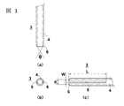
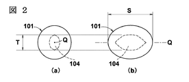
図1に、本発明を適用する種押出部材3を示す。図1(a)は平面図、図1(b)は正面図、図1(c)は側面図で種押出部材3を示している。この種押出部材3は、一例として、図2に示す果実101に使用される。図2(a)は正面図、図2(b)は側面図で果実101を示している。図2に示す果実101は一例としてプルーンであり、長球(長軸が回転軸になった回転楕円体)にモデル化して図示している。
FIG. 1 shows a
図1に示す種押出部材3は、果実101に刺し込んで種104を押し出すためのものである。種押出部材3は、中空パイプ4、中空パイプ4に形成された刃部6、及び中空パイプ4に形成されたスリット5を有している。同図では、スリット5の設けられた中空パイプ4の先端側の部位を図示している。同図では、中空パイプ4が丸パイプの例を図示しているが、中空パイプ4は角パイプであってもよい。
The
中空パイプ4は、金属で形成されている。中空パイプ4は、種104が中空パイプ4の内部に入り込まずに種104を押せるように、種104の外周形状よりも小さな孔サイズの孔径Kで形成されている。中空パイプ4(種押出部材3)は、果実101の長軸Qが中空パイプ4の軸と一致する向きで果実101に刺し込むことを想定している(図3参照)。そのため、中空パイプ4の孔径Kは、中空パイプ4(種押出部材3)の刺し込み方向から見た種104の外周形状、つまり図2(a)に示した種104の外周形状よりも小さく形成されている。中空パイプ4の刺し込み方向から見た種104の外周形状の最大幅T>中空パイプ4の孔径Kの関係になる。
The
刃部6は、果実101に刺し込むために中空パイプ4の先端側の縁に設けられている。例えば、刃部6は、中空パイプ4の縁部の肉厚が先端側に向かって薄くなるように、縁部を斜めに削った形状に形成されている。図1(a)に示すように、対向する刃部6の延長線が角度θで交わる。角度θは、鋭角になるほど、果実101に刺し込みやすくなる。
The
スリット5は、中空パイプ4の先端から中空パイプ4の途中まで設けられている。スリット5は、長さLで形成されている。中空パイプ4には、互いに対向する位置関係で2本(複数本の一例)のスリット5が設けられている。スリット幅Wは、種押出部材3を果実101に押し込んだときの押し圧に耐えられるばね性が保持できる幅とする。又、中空パイプ4の肉厚とのバランスを考慮したスリット幅Wとする。
The
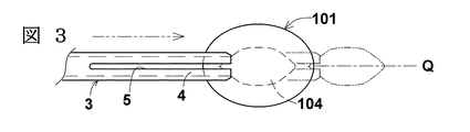
図3に、種押出部材3の使用状態を示す。果実101を予め保持しておいてから、同図に示すように、種押出部材3の軸を果実101の長軸Qに位置合わせして刺し込み、同図中に二点鎖線で示すように、種104を押し出す。種104を押し出した後、種押出部材3を果実101から引き抜く。
In FIG. 3, the use condition of the
種104を長軸Q方向に押し出す場合、短軸方向に押し出す場合よりも種104の外周形状(断面積)が小さいため、果実101からスムーズに種104を押し出すことができる共に、果実101の傷を小さくできる。
When the
図4に、種押出部材3を引き抜いた後の果実101の正面図を示す。刺し跡106は種押出部材3が刺し込まれた跡である。種押出部材3のスリット5に対応して、果実101には、種押出部材3(中空パイプ4)の内部に入った果肉112と、その周囲の果肉111を繋ぐ接続部108が出来る。この接続部108により、果肉112が種104と一緒に排出されてしまったり、中空パイプ4の中に取り残されてしまったりすること無く、果肉112が果肉111に繋がった状態で残る。したがって、果肉の残留歩留まりを向上させることができる。
FIG. 4 shows a front view of the
スリット5の長さL(図1参照)は、種押出部材3を刺し込む側の果実101の正面側まで接続部108が出来るように、種押出部材3(中空パイプ4)を果実101に刺し込む長さよりも長い長さに形成されていることが好ましい。種104を押し出すために、果実101の長軸Q方向の長さS(図2参照)よりも種押出部材3(中空パイプ4)を長い長さで刺し込むことが好ましいため、スリット5の長さLは、果実101の長さSよりも長い長さ(L>S)に形成されていることが好ましい。
The length L of the slit 5 (see FIG. 1) is such that the seed extrusion member 3 (hollow pipe 4) is pierced into the
接続部108が弱いと果肉112が果肉111から千切れて回収できなくなるため、接続部108の幅を広くして強くするように、スリット幅W(図1参照)を適度な広い幅で形成することが好ましい。又、接続部108を複数設けた方が強度を高くでき果肉112が千切れにくくなるため、種押出部材3に複数のスリット5を設けることが好ましい。本例では、2本のスリット5を設けている例を示しているが、3本、4本等の任意の数のスリット5を設けてもよい。
If the
前述したように、本発明の種押出部材3を用いると果肉の残留歩留まりを向上させることができる。種押出部材3を用いるためには、刺し込むときに果実101を保持することや、果実101の長軸Qに位置合わせして種押出部材3を刺し込むことが必要である。以下では、種押出部材3を用いるのに適した種抜き装置1について説明する。
As described above, when the
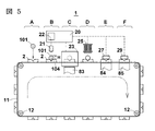
図5に、本発明を適用する種抜き装置1の正面図を模式的に示す。種抜き装置1は、果実101、101・・・を1つずつ載置するための載置台2、2・・・、及び図中に二点鎖線矢印で示した方向に載置台2、2・・・を間欠的に搬送する搬送手段11を備えている。搬送手段11は、載置台2を搬送可能であれば公知のどのような構造のものであってもよいが、一例としてチェーンコンベアである。チェーンコンベアは、駆動用歯車12、12・・・によって間欠的に搬送駆動されるように構成されている。
FIG. 5 schematically shows a front view of the seeding
種抜き装置1は、果実載置ステージA、高さ測定ステージB、種抜きステージC、検査ステージD、不良品除去ステージE、及び良品収集ステージFを有して構成されている。同図に示すように、搬送手段11によって、載置台2は、ステージA→B→C→D→E→Fの順番に移動する。種抜き装置1の各部の動作はコンピュータ20によって総合的に制御されている。
The
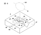
図6に、載置台2の斜視図を示す。載置台2は、一例として直方体形状に形成されている。この例では、載置台2の上面の中央部が、果実101の載置位置(果実101を載置すべき位置)になっている。載置台2の上面には、果実101の載置位置から、載置台2の一側面37まで延びているガイド溝31が設けられている。このガイド溝31は、種104を抜く際に果実101の移動をガイドするための溝である。ガイド溝31は、一例として断面が略V字型形状に形成されている。載置台2の中央部側のガイド溝31の端部は、上側に向かって拡開するように傾斜した斜面33になっている。
FIG. 6 shows a perspective view of the mounting table 2. The mounting table 2 is formed in a rectangular parallelepiped shape as an example. In this example, the center part of the upper surface of the mounting table 2 is the mounting position of the fruit 101 (the position where the
載置台2には、果実101の載置位置のガイド溝31側に配置され、果実101の載置位置に果実101を位置合わせすると共に、ガイド溝31に沿った果実101の移動を妨げるための係止部材41が設けられている。果実101は、略V字型形状のガイド溝31、斜面33、及び係止部材41によって囲まれた窪み領域に嵌り、載置台2の中央部に保持される。果実101は長球であるので、同図に示すように果実101を横に寝かせて長軸Qがガイド溝31に沿う状態で嵌るように、ガイド溝31、斜面33、及び係止部材41が設定されている。長球は立てるよりも寝かせた方が安定するため、果実101は安定して載置台2に載置される。ガイド溝31が略V字型に形成されているため、果実101の外周形状の大小によらず、つまり短軸方向の外径M(図7参照)の大小によらずガイド溝31に果実101が保持されると共に、ガイド溝31の中心(溝に沿う方向の中心)上に果実101の軸Qが位置する(図7参照)。
The mounting table 2 is disposed on the
ガイド溝31の溝底及び斜面33には、載置台2の内部側からガイド溝31内に係止部材41が突き出すための突き出し孔35が形成されている。載置台2の内部は、係止部材41の動きに干渉しないように、下面側が凹状に窪んだ形状に形成されている。
In the groove bottom and the
係止部材41は、所定の力を超えた力でガイド溝31側(一側面37側)に押されたときに倒れ、果実101の移動を妨げなくなるような可倒式機構で載置台2に支持されている。具体的には、係止部材41は、一例として、板材42、重り47、中空軸51、支持軸53、及びストッパー55を備えて構成されている。板材42は、開角度が鈍角の略V字型(逆への字型)に形成されている。ガイド溝31に突き出る側の板材42の先端部44は、果実101の表面に擦れるため、滑らかに擦れるように円弧形状に形成されている。板材42の中央部付近に形成された貫通孔43には、中空軸51が挿通されて板材42と一体的に固定されている。中空軸51の内部には、支持軸53が挿通されている。支持軸53の両端は、載置台2に固定されている。このため、支持軸53を軸心として、中空軸51に固定された板材42が回転可能になっている。
The locking
板材42には、先端部44とは逆側の他端部46に重り47が固定されている。この重り47により、支持軸53を軸心として板材42が回転し、板材42の先端部44側が上がり、他端部46側が下がるようになっている。先端部44が適度な高さに位置するように、重り47側の板材42の下部に当たるストッパー55が載置台2に固定されている。
A
係止部材41は、板材42の先端部44側が一側面37側に押されると、押された力が重り47の作用する力(所定の力)を超えている場合に回転し、先端部44の位置が下がり倒れるように動く。
When the
なお、重り47に換え、コイルばねや板ばねなどの弾性体を用いた可倒式機構で係止部材41を支持してもよい。
Instead of the
図5に示す果実載置ステージAは、載置台2の中央部(載置位置)に果実101を載置するステージである。果実載置ステージAでは、人手又は自動載置ロボット(図示せず)によって、前述したように果実101の長軸Q(図6参照)が載置台2のガイド溝31に沿う向きになるように、載置台2の中央部に載置される。果実101を載置した載置台2は高さ測定ステージBに移動する。
The fruit placement stage A shown in FIG. 5 is a stage on which the
高さ測定ステージBは、載置台2に載置された果実101の上部の高さHを測定して、種104の中心の高さを演算するステージである。高さ測定ステージBは、果実101の上部の高さHを測定するための高さ測定手段21、及び、果実101の上部の高さHに基づいて種104の中心の高さを演算する演算手段22を備えている。
The height measuring stage B is a stage that measures the height H of the upper part of the
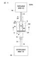
図7に、高さ測定ステージBを模式的に示す正面図を示す。搬送手段11の図示は省略している。 FIG. 7 is a front view schematically showing the height measurement stage B. Illustration of the transport means 11 is omitted.
高さ測定手段21は、果実101の上部までの距離を検出可能な公知のどのような測定器であってもよい。例えば、高さ測定手段21は、レーザー式距離センサのような非接触式距離センサ、デジタルゲージ若しくは測長エアシリンダのような接触式距離センサ、又は、カメラ及び画像処理装置を用いて距離を測長する測長システムである。同図では、高さ測定手段21の例としてレーザー式距離センサを図示している。
The height measuring means 21 may be any known measuring device that can detect the distance to the top of the
演算手段22として、装置の動作を制御するコンピュータ20が兼用して用いられている。
A
高さ測定ステージBでは、先ず、高さ測定手段21が果実101の上部位置について高さ(距離)の測定を行う。この測定結果により、演算手段22が、例えば、載置台2の上面(基準位置)から果実101の上部までの高さHを演算する。基準位置は別の位置であってもよい。演算手段22は、高さHに基づいて、載置台2の上面(基準位置)から種104の中心までの高さh1を演算する。
In the height measurement stage B, first, the height measurement means 21 measures the height (distance) for the upper position of the
演算手段22は、例えば、果実101の短軸方向の外径が円形であるものとして、果実101の上部の高さH、ガイド溝31のV字型の斜面の角度、及びガイド溝31の溝の深さから果実101の直径Mを演算する。演算手段22は、直径Mの円の中心(長軸Q)が種104の中心であるものとして、載置台2の上面(基準位置)から種104の中心の高さh1を演算する。演算が終了すると、載置台2は種抜きステージCに移動する。
For example, the computing means 22 assumes that the
図5に示す種抜きステージCは、果実101から種104を抜くステージである。種抜きステージCは、種抜き機構23を備えている。抜かれた種は、一例として、滑り台のような経路に形成されたシューター83を通って所定の場所に溜められる。
The seed removal stage C shown in FIG. 5 is a stage in which the
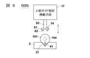
図8に、種抜きステージCを上側から見た種抜き機構23の平面図を示し、図9に、図8中にP−P線で示した位置から見た種抜き機構23の正面図を示し、図10に、種扱き部材7の正面図を示し、図11、図12に、種抜きステージCの動作を示す図8中のG−G線断面図を示す。なお、図8では、図9に示した上部ガイド部材移動手段17の図示を省略している。又、各図では、搬送手段11の図示を省略している。
FIG. 8 shows a plan view of the seeding
図8、図9に示すように、種抜きステージCは、種抜き機構23として、種押出部材3、種押出部材移動手段15、種扱き部材7、果実押返部材13、果実押返部材移動手段16、上部ガイド部材14、上部ガイド部材移動手段17、及び位置合せ手段18(図11(1)参照)を備えている。種押出部材移動手段15、果実押返部材移動手段16、上部ガイド部材移動手段17、及び位置合せ手段18は、コンピュータ20(図5参照)によって、動作を制御されている。又、種押出部材移動手段15、果実押返部材移動手段16、上部ガイド部材移動手段17、及び位置合せ手段18には、電力、圧縮空気、又は油圧を利用して駆動可能なアクチュエータ、シリンダなどの公知の駆動装置が用いられている。
As shown in FIGS. 8 and 9, the seeding stage C is used as a seeding
種抜きステージCでは、図8、図9に示す位置に載置台2が搬送されて停止する。載置台2のガイド溝31が繋がる一側面37の横に位置するように、種扱き部材7が配置されている。
In the seed removal stage C, the mounting table 2 is transported to the position shown in FIGS. 8 and 9 and stopped. The
種扱き部材7は、弾性変形する合成樹脂で形成された板材である。種扱き部材7は、例えば、バンコラン(登録商標)などの低摩耗性ウレタンゴムで形成されたものであることが好ましい。図10(a)に示すように、種扱き部材7の中央部には、扱き孔8が形成されている。扱き孔8は、種押出部材3の刺し込み方向から見た種104の外周形状よりも小さな形状に形成されている。種扱き部材7は、種104が扱き孔8に押し当てられたときに扱き孔8が押し広げられて種104が通過可能であるように板材及び扱き孔8が構成されている(図11(4)参照)。
The
図10(a)に示すように、種扱き部材7は、外形が四角形状に形成されており、その4辺を枠9によって挟まれて保持されている。種扱き部材7及び枠9の形状が円形、又は多角形に形成されていてもよい。枠9は図示しないが種抜き装置1に支持されている。図10(a)は、扱き孔8が円形に形成されている種扱き部材7の例である。扱き孔8は、図10(b)、(c)のように形成されていてもよい。図10(b)は、扱き孔8が種押出部材3の刺し込み方向から見た種104の外周形状の相似形に形成されている例である。図10(c)は、図10(b)の扱き孔8の縁から放射状に延びるように複数(例えば4本)の切れ込み58が形成されている例である。
As shown in FIG. 10A, the
図8に示すように、種押出部材3は、種扱き部材7の配置された載置台2の一側面37側とは反対側の載置台2の横に配置されている。種押出部材3は、種押出部材移動手段15によって移動可能に構成されている。種押出部材移動手段15は、種押出部材3を、載置台2の上に載置された果実101を種扱き部材7に押し付けて果実101に刺し込み、種104を押し出すように、果実101の横方向から種扱き部材7の扱き孔8に向かって移動させるものである。
As shown in FIG. 8, the
果実押返部材13は、棒状に形成されており、載置台2に対して種扱き部材7よりも外側に配置されている。果実押返部材13は、果実押返部材移動手段16によって移動可能に構成されている。果実押返部材13は、種扱き部材7に付着した果実101を載置台2側に押し返すものである。果実押返部材13及び果実押返部材移動手段16は、本発明における果実押返手段の一例である。
The fruit push-
図9に示すように、載置台2の上方には、上部ガイド部材14が配置されている。上部ガイド部材14は、果実101の上部に当接可能に構成されている。上部ガイド部材14は、種扱き部材7の方向への果実101の移動をガイドするためのものである。上部ガイド部材14は、シャフト63で繋がる上部ガイド部材移動手段17によって上下方向に移動可能に構成されている。上部ガイド部材14は、一例として、平坦な板材61、及び板材61の下面に設けられた2本の平行なガイドレール62で構成されている。ガイドレール62は、ガイド溝31の上方に位置し、ガイド溝31に平行に沿うように板材61に設けられている。上部ガイド部材14を下方に下げたときに、2本のガイドレール62が果実101の上部に当たるように、ガイドレール62の間隔や大きさ(径)が設定されている。
As shown in FIG. 9, an
図8、図11(1)に示すように、種押出部材3(中空パイプ4)の中心軸、扱き孔8の中心、及び果実押返部材13の中心軸が共通の軸Rに一致するように、種押出部材3、種扱き部材7、及び果実押返部材13の位置関係が設定されている。さらに、図11(1)に示すように、種押出部材3、種扱き部材7、及び果実押返部材13が軸Rに一致するように互いの位置関係を保ったまま上下方向に移動可能に位置合せ手段18が構成されている。
As shown in FIGS. 8 and 11 (1), the central axis of the seed extruding member 3 (hollow pipe 4), the center of the
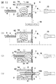
図11、図12を参照して、種抜きステージCの動作を説明する。 The operation of the seed removal stage C will be described with reference to FIGS.
図11(1)に示すように、種抜きステージCに搬送されてきた果実101の長軸Q(種104の中心)と、種押出部材3、扱き孔8、及び果実押返部材13の軸Rとの高さには差が生じている。この差は、個々の果実101の大きさに違いがあるため、果実101毎に違う差になる。種104の中心の長軸Qの高さh1(図7参照)は、前段の高さ測定ステージBで求められている。種押出部材3、扱き孔8、及び果実押返部材13の軸Rの高さは、位置合せ手段18により制御可能である。又、果実101の高さH(図7参照)は、前段の高さ測定ステージBで測定している。上部ガイド部材14の高さは、上部ガイド部材移動手段17(図7参照)により制御可能である。
As shown in FIG. 11 (1), the long axis Q (the center of the seed 104) of the
図11(2)に示すように、位置合せ手段18は、種104の中心の高さh1に基づいて、長軸Qと軸Rとが一致するように、種押出部材3、種扱き部材7、及び果実押返部材13を上下方向に移動させる。さらに、上部ガイド部材移動手段17(図7参照)が、果実101の高さHの位置まで上部ガイド部材14を下降(移動)させ、上部ガイド部材14のガイドレール62を果実101の上部に当接させる。
As shown in FIG. 11 (2), the alignment means 18 is based on the height h1 of the center of the
続いて、図11(3)に示すように、種押出部材移動手段15(図8参照)が、種押出部材3を種扱き部材7の扱き孔8に向けて水平に移動させる。種押出部材3を移動させる力は係止部材41を押し倒すために必要な所定の力を超える力である。そのため、係止部材41が倒れ、果実101が移動して種扱き部材7に押し付けられる。このとき、果実101は、ガイド溝31、及び上部ガイド部材14のガイドレール62によって、種扱き部材7方向への移動をガイドされる。又、種押出部材3が果実101のちょうど真ん中を押す。そのため、果実101は、長軸Qと軸Rとがほぼ一致した姿勢のまま移動して、種扱き部材7に押し付けられる。
Subsequently, as shown in FIG. 11 (3), the seed pushing member moving means 15 (see FIG. 8) moves the
続いて、図11(4)に示すように、種押出部材3がさらに移動して果実101に突き刺さり、種104を押して扱き孔8を通ることで、果実101から種104を押し出す。押し出された種104は、シューター83(図5参照)に落下する。
Subsequently, as shown in FIG. 11 (4), the
前述したように、種押出部材3にはスリット5が形成されているため、種押出部材3の中の果肉112(図4参照)を回収することができる。さらに、扱き孔8を種104が押し通るときに、種104の周囲に付着した果肉が扱かれて回収できるため、果肉の残留歩留まりを一層高くすることができる。
As described above, since the
続いて、図12(5)に示すように、種押出部材3が後退する。種104の抜かれた果実101は、同図中に二点鎖線で示すように載置台2の載置位置まで戻るものもあれば、同図に実線で示すように種扱き部材7に付着してしまうものもある。
Subsequently, as shown in FIG. 12 (5), the
そこで、図12(6)に示すように、果実押返部材13が載置台2の外側から扱き孔8を押し通るように、果実押返部材移動手段16(図8参照)が移動させる。これにより、果実101が載置台2の上に押し戻される。上部ガイド部材移動手段17(図7参照)は、果実押返部材13を移動させる前又は後に、上部ガイド部材14を上方の待機位置に戻すように移動させる。
Therefore, as shown in FIG. 12 (6), the fruit pushing member moving means 16 (see FIG. 8) is moved so that the
続いて、図12(7)に示すように、果実押返部材13を元の待機位置まで戻すように果実押返部材移動手段16(図8参照)が移動させて、種抜きステージCの工程が終了する。載置台2は、次に検査ステージDに移動する。
Subsequently, as shown in FIG. 12 (7), the fruit pushing member moving means 16 (see FIG. 8) moves so as to return the
図5に示す検査ステージDは、果実101から種104が抜かれたか否か、つまり種の有無を検査するステージである。検査ステージDは、検査手段25を備えている。
The inspection stage D shown in FIG. 5 is a stage for inspecting whether or not the
図13に、検査ステージD(検査手段25)の一例を模式的に正面図で示す。搬送手段11の図示は省略している。 FIG. 13 is a front view schematically showing an example of the inspection stage D (inspection means 25). Illustration of the transport means 11 is omitted.
図13(1)に示すように、検査手段25は、検査器71、検査器移動手段72、及び検出器73を備えている。検査器71は、例えば複数の検査針である。検査器移動手段72は、検査器71を上下方向に移動可能に構成されている。検査器移動手段72は、公知の駆動装置であり、コンピュータ20(図5参照)によって、動作を制御されている。検出器73は、一例として、検査器71の位置によってオン/オフするスイッチである。一例として、検査器71が下方の載置台2まで下がっているときに検出器73がオン、検査器71が載置台2まで下がらないときには検出器73がオフになるように設定されている。
As shown in FIG. 13 (1), the inspection means 25 includes an
検査ステージDでは、検査器移動手段72が検査器71を載置台2に向けて下降させる。果実101から種104が抜けている場合、図13(2)に示すように、検査器71が果実101に刺さって載置台2まで下降する。このため、検出器73がオンになる。一方、果実101から種104が抜けていない場合、図13(3)に示すように、検査器71(検査針)が種104に当たり、載置台2まで下がらず停止する。このため、検出器73はオフである。このように、検出器73のオン/オフによって種104の有無を検査することができる。検出器73の検出した検査結果は、コンピュータ20に出力される。検査が終了すると、検査器移動手段72が検査器71を上方の待機位置に戻し、載置台2は次の不良品除去ステージEに移動する。
In the inspection stage D, the inspection device moving means 72 lowers the
なお、検査手段25として検査針を使用した例を示したが、種104を検出可能な公知の接触式又は非接触式の種々の検査装置を用いることができる。
In addition, although the example which used the test needle as the test | inspection means 25 was shown, the well-known various contact-type or non-contact-type test | inspection apparatus which can detect the seed |
図5に戻って説明を続けると、不良品除去ステージEは、前段の検査ステージDで種104が抜けていないと判別された果実101を除去するステージである。不良品除去ステージEは、載置台2から果実101を押し出してシューター84に落下させる仕分手段27を備えている。仕分手段27は、コンピュータ20によって動作を制御されている。このような仕分手段27として、公知の仕分装置を用いることができる。落とされた果実101は、一例として、滑り台のような経路に形成されたシューター84を通って所定の場所に溜められる。
Returning to FIG. 5 and continuing the description, the defective product removal stage E is a stage for removing the
良品収集ステージFは、検査ステージDで種104が抜けていると判別された果実101を集めるステージである。良品収集ステージFは、載置台2から果実101を押し出してシューター85に落下させる仕分手段29を備えている。仕分手段29は、コンピュータ20によって動作を制御されている。このような仕分手段29として、公知の仕分装置を用いることができる。落とされた果実101は、一例として、滑り台のような経路に形成されたシューター85を通って所定の場所に溜められる。
The non-defective product collection stage F is a stage for collecting the
種抜き装置1では、複数の載置台2が各々果実101を載せて各ステージAからFまで順次搬送されていくことで、大量の果実101の種104を自動的に抜くことができる。
In the seeding
なお、果実101が長球に近い形状の例について説明したが、果実101が球、短球、扁平の楕円体に近い形状であってもよい。ガイド溝31の溝形状や、上部ガイド部材14の形状は、果実101の形状に合わせて適宜変更することができる。上部ガイド部材14がガイドレール62を有する例を示したが、上部ガイド部材14がガイド溝31のような略V字型形状のガイド溝を有するようにしてもよい。又、載置台2がガイド溝31に換えて2本のガイドレールを備えていてもよい。ガイド溝31、及び上部ガイド部材14を備えた例を説明したが、必要性に応じて、いずれか一方だけを備えるようにしてもよい。
In addition, although the example of the shape in which the
果実101がプルーンである例を説明したが、果実101が杏子、梅、プラム、ネクタリン、サクランボ、スモモ、桃、マンゴー、オリーブなどの種を一つ有する核果であれば本発明の種押出部材3、及び種抜き装置1を使用することができる。又、果実101が、梅干しのように加工したものであってもよい。
The example in which the
種抜き装置1として、高さ測定ステージB、種抜きステージCを2つに分けて構成した例を説明したが、これらを1つのステージ(場所)で行うように構成してもよいし、3つ以上のステージで行うように構成してもよい。必要性に応じて、他のステージの構成を変えてもよい。不良品除去ステージEと良品収集ステージFとの順番を逆にしてもよい。又、種抜きステージCが果実押返手段になる果実押返部材13及び果実押返部材移動手段16を備えた例を説明したが、果実押返手段として、エアーを吹き付けて果実101を押し返すエアー噴射器を備えてもよい。又、種抜きステージCが果実押返部材13及び果実押返部材移動手段16を備えた例を説明したが、種抜きした果実101が種扱き部材7に付着しないで載置台2上に戻る場合には、果実押返部材13及び果実押返部材移動手段16の構成を省略してもよい。又、位置合せ手段18が種押出部材3、種扱き部材7、及び果実押返部材13を上下方向に移動させる例を説明したが、載置台2を上下方向に移動させてもよい。又、果実101の大きさがほぼ揃っている場合には、位置合せ手段18の構成を省略してもよい。
The example in which the height measuring stage B and the seeding stage C are divided into two parts has been described as the seeding
載置台2及び上部ガイド部材14により種抜きの際に果実101を保持した例を説明したが、ロボットアーム等の他の構成で果実101を保持するようにしてもよい。種押出部材3を横方向(水平方向)に移動させる例を説明したが、上下方向(垂直方向)に移動させてもよい。
Although the example which hold | maintained the
1は種抜き装置、2は載置台、3は種押出部材、4は中空パイプ、5はスリット、6は刃部、7は種扱き部材、8は扱き孔、9は枠、11は搬送手段、12は駆動用歯車、13は果実押返部材、14は上部ガイド部材、15は種押出部材移動手段、16は果実押返部材移動手段、17は上部ガイド部材移動手段、18は位置合せ手段、20はコンピュータ、21は高さ測定手段、22は演算手段、23は種抜き機構、25は検査手段、27は仕分手段、29は仕分手段、31はガイド溝、33は斜面、35は突き出し孔、37は一側面、41は係止部材、42は板材、43は貫通孔、44は先端部、46は他端部、47は重り、51は中空軸、53は支持軸、55はストッパー、58は切れ込み、61は板材、62はガイドレール、63はシャフト、71は検査器、72は検査器移動手段、73は検出器、83・84・85はシューター、101は果実、104は種、106は刺し跡、108は接続部、111・112は果肉、Aは果実載置ステージ、Bは高さ測定ステージ、Cは種抜きステージ、Dは検査ステージ、Eは不良品除去ステージ、Fは良品収集ステージ、Hは果実101の上部の高さ、h1は種104の中心の高さ、Kは中空パイプ4の孔径(内径)、Lはスリット5の長さ、Mは果実101の短軸方向の外径、Qは果実101の長軸、Rは軸、Sは果実101の長軸Q方向の長さ、Tは種104の外周形状の最大幅、Wはスリット幅、θは角度である。
DESCRIPTION OF
Claims (10)
前記種の外周形状よりも小さな孔サイズの中空パイプと、
前記果実に刺し込むために前記中空パイプの先端の縁に設けられた刃部と、
前記中空パイプの先端から前記中空パイプの途中まで設けられたスリットとを、
備えることを特徴とする種押出部材。 A seed extruding member for extruding a seed by piercing the fruit,
A hollow pipe with a pore size smaller than the outer peripheral shape of the seed,
A blade provided at the edge of the tip of the hollow pipe to pierce the fruit;
A slit provided from the tip of the hollow pipe to the middle of the hollow pipe,
A seed extruding member comprising:
前記果実を載置するための載置台と、
前記載置台の横に位置するように配置され、弾性変形する板材に前記種の外周形状よりも小さな形状の扱き孔が形成されていて、前記扱き孔に前記種が押し当てられたときに前記扱き孔が押し広げられて前記種が通過可能であるように前記板材及び前記扱き孔が構成されている種扱き部材と、
前記載置台の上に載置された前記果実の横方向から前記扱き孔に向かって前記種押出部材を移動可能な種押出部材移動手段とを、
備えることを特徴とする種抜き装置。 A seed extrusion member according to any one of claims 1 to 3,
A mounting table for mounting the fruit;
When the handling hole having a shape smaller than the outer peripheral shape of the seed is formed in the plate material that is arranged to be positioned beside the mounting table and is elastically deformed, the seed is pressed against the handling hole. A seed handling member in which the plate material and the handling hole are configured so that the handling hole is expanded and the seed can pass through;
Seed extruding member moving means capable of moving the seed extruding member from the lateral direction of the fruit placed on the mounting table toward the handling hole,
A seed removal device comprising:
前記係止部材は、所定の力を超えた力で前記ガイド溝側に押されたときに倒れて前記果実の移動を妨げなくなる可倒式機構で支持されていることを特徴とする請求項5に記載の種抜き装置。 The mounting table is arranged on the guide groove side of the position where the fruit is to be placed, aligns the fruit at a position where the fruit is to be placed, and moves the fruit along the guide groove. A locking member is provided to prevent
6. The locking member is supported by a retractable mechanism that falls when it is pushed toward the guide groove with a force exceeding a predetermined force and does not prevent the movement of the fruit. The seed removal device described in 1.
前記測定手段の測定した前記果実の高さから前記種の中心の高さを演算する演算手段と、
前記演算手段の演算した前記種の中心の高さに基づいて、前記種の中心、前記種押出部材の中空パイプの中心軸、及び前記扱き孔の中心の位置合せをする位置合せ手段とを、
備えることを特徴とする請求項4から8のいずれかに記載の種抜き装置。 Measuring means for measuring the height of the fruit placed on the mounting table,
A calculating means for calculating the height of the center of the seed from the height of the fruit measured by the measuring means;
Based on the height of the center of the seed calculated by the calculation means, alignment means for aligning the center of the seed, the central axis of the hollow pipe of the seed extrusion member, and the center of the handling hole,
The seed removal device according to any one of claims 4 to 8, further comprising:
前記測定手段の測定した前記果実の高さから前記種の中心の高さを演算する演算手段と、
前記演算手段の測定した前記果実の高さに基づいて、前記上部ガイド部材を移動させて前記果実の上部に当接させる上部ガイド部材移動手段と、
前記演算手段の演算した前記種の中心の高さに基づいて、前記種の中心、前記種押出部材の中空パイプの中心軸、及び前記扱き孔の中心の位置合せをする位置合せ手段とを、
備えることを特徴とする請求項8に記載の種抜き装置。 Measuring means for measuring the height of the fruit placed on the mounting table,
A calculating means for calculating the height of the center of the seed from the height of the fruit measured by the measuring means;
Based on the height of the fruit measured by the computing means, the upper guide member moving means for moving the upper guide member and contacting the upper part of the fruit;
Based on the height of the center of the seed calculated by the calculation means, alignment means for aligning the center of the seed, the central axis of the hollow pipe of the seed extrusion member, and the center of the handling hole,
The seeding device according to claim 8, further comprising:
Priority Applications (1)
| Application Number | Priority Date | Filing Date | Title |
|---|---|---|---|
| JP2016093515A JP2017200460A (en) | 2016-05-07 | 2016-05-07 | Seed extrusion member and seed removal device |
Applications Claiming Priority (1)
| Application Number | Priority Date | Filing Date | Title |
|---|---|---|---|
| JP2016093515A JP2017200460A (en) | 2016-05-07 | 2016-05-07 | Seed extrusion member and seed removal device |
Publications (1)
| Publication Number | Publication Date |
|---|---|
| JP2017200460A true JP2017200460A (en) | 2017-11-09 |
Family
ID=60264302
Family Applications (1)
| Application Number | Title | Priority Date | Filing Date |
|---|---|---|---|
| JP2016093515A Pending JP2017200460A (en) | 2016-05-07 | 2016-05-07 | Seed extrusion member and seed removal device |
Country Status (1)
| Country | Link |
|---|---|
| JP (1) | JP2017200460A (en) |
Cited By (4)
| Publication number | Priority date | Publication date | Assignee | Title |
|---|---|---|---|---|
| CN109222119A (en) * | 2018-08-21 | 2019-01-18 | 安徽有余跨越瓜蒌食品开发有限公司 | A kind of PERICARPIUM TRICHOSANTHIS flesh separator |
| CN110881668A (en) * | 2019-12-04 | 2020-03-17 | 湖南和畅(常德)食品科技有限公司 | Sesame oil production is with sesame oil seed cutting device convenient to material loading |
| CN114393865A (en) * | 2022-01-28 | 2022-04-26 | 中国农业科学院郑州果树研究所 | Kiwi fruit kind belt cleaning device |
| JP7427260B2 (en) | 2021-08-17 | 2024-02-05 | 有限会社森満工業 | Seed removal device and seed removal method |
Citations (8)
| Publication number | Priority date | Publication date | Assignee | Title |
|---|---|---|---|---|
| US3817168A (en) * | 1972-02-22 | 1974-06-18 | Gunsons Sortex Ltd | Fruit pitting machine |
| US4905584A (en) * | 1986-11-19 | 1990-03-06 | Sociedad De Racionalizacion Y Mecanizacion (Sadrym) | Pitting-and-stuffing olives, a device for working it and the product obtained therefrom |
| US5722318A (en) * | 1995-11-17 | 1998-03-03 | Sociedad Anonimya De Racionalizacion Y Mecanizacion (Sadrym) | Olive stoning machines |
| JP2005279211A (en) * | 2004-03-30 | 2005-10-13 | Akio Otsuka | Deseeding apparatus for pickled ume |
| JP2005278538A (en) * | 2004-03-30 | 2005-10-13 | Hamachi Tekkosho:Kk | Fruit-deseeding apparatus |
| JP2009544420A (en) * | 2006-07-27 | 2009-12-17 | ヘレン オブ トロイ リミテッド | Equipment for removing food nuclei |
| JP2016002063A (en) * | 2014-06-19 | 2016-01-12 | 丸長水産株式会社 | Fruit seed extracting device and method |
| JP2016021894A (en) * | 2014-07-17 | 2016-02-08 | 行男 黒木 | Seed removing tool |
-
2016
- 2016-05-07 JP JP2016093515A patent/JP2017200460A/en active Pending
Patent Citations (8)
| Publication number | Priority date | Publication date | Assignee | Title |
|---|---|---|---|---|
| US3817168A (en) * | 1972-02-22 | 1974-06-18 | Gunsons Sortex Ltd | Fruit pitting machine |
| US4905584A (en) * | 1986-11-19 | 1990-03-06 | Sociedad De Racionalizacion Y Mecanizacion (Sadrym) | Pitting-and-stuffing olives, a device for working it and the product obtained therefrom |
| US5722318A (en) * | 1995-11-17 | 1998-03-03 | Sociedad Anonimya De Racionalizacion Y Mecanizacion (Sadrym) | Olive stoning machines |
| JP2005279211A (en) * | 2004-03-30 | 2005-10-13 | Akio Otsuka | Deseeding apparatus for pickled ume |
| JP2005278538A (en) * | 2004-03-30 | 2005-10-13 | Hamachi Tekkosho:Kk | Fruit-deseeding apparatus |
| JP2009544420A (en) * | 2006-07-27 | 2009-12-17 | ヘレン オブ トロイ リミテッド | Equipment for removing food nuclei |
| JP2016002063A (en) * | 2014-06-19 | 2016-01-12 | 丸長水産株式会社 | Fruit seed extracting device and method |
| JP2016021894A (en) * | 2014-07-17 | 2016-02-08 | 行男 黒木 | Seed removing tool |
Cited By (6)
| Publication number | Priority date | Publication date | Assignee | Title |
|---|---|---|---|---|
| CN109222119A (en) * | 2018-08-21 | 2019-01-18 | 安徽有余跨越瓜蒌食品开发有限公司 | A kind of PERICARPIUM TRICHOSANTHIS flesh separator |
| CN109222119B (en) * | 2018-08-21 | 2021-05-14 | 安徽趣健乐食品科技有限公司 | Trichosanthes peel flesh separator |
| CN110881668A (en) * | 2019-12-04 | 2020-03-17 | 湖南和畅(常德)食品科技有限公司 | Sesame oil production is with sesame oil seed cutting device convenient to material loading |
| JP7427260B2 (en) | 2021-08-17 | 2024-02-05 | 有限会社森満工業 | Seed removal device and seed removal method |
| CN114393865A (en) * | 2022-01-28 | 2022-04-26 | 中国农业科学院郑州果树研究所 | Kiwi fruit kind belt cleaning device |
| CN114393865B (en) * | 2022-01-28 | 2024-01-19 | 中国农业科学院郑州果树研究所 | A kind of kiwi fruit seed cleaning device |
Similar Documents
| Publication | Publication Date | Title |
|---|---|---|
| US8930015B2 (en) | Sorting system for damaged product | |
| US10292414B1 (en) | Apparatus and method for fruit decapping | |
| EP3196648A1 (en) | Device for lifting a sample tube | |
| US11637039B2 (en) | Method of processing wafer, and chip measuring apparatus | |
| EP2194008B1 (en) | Method and device for storing packets of medicine | |
| JP2020504681A (en) | Gripper for test sample, positioning device for raw sample, handling system for raw sample and test sample, and test system for viscoelastic material | |
| CN105775640B (en) | A kind of double track connection platform and its operation method and the automatic production line using double track connection platform | |
| CN105478367B (en) | A kind of chamfer detecting device and detection method | |
| KR20060066141A (en) | Machine for precisely decoiling and slicing apples and other fruits with soft cores or feet with small stresses | |
| JP2015003284A (en) | Selector | |
| JPWO2014087485A1 (en) | Electronic component transfer device and taping unit | |
| EP3070012A1 (en) | Tray sealing machine | |
| CN103357587B (en) | On-machine automatic separation blanking device facing picker cold forging process | |
| CN106140647B (en) | Detection device | |
| EP1748004B1 (en) | Method and device for measuring and positioning a cuboidal piece of goods | |
| CN214555452U (en) | Integrated IC appearance defect detection device | |
| CN112098410A (en) | Pineapple water core disease rating equipment and method | |
| WO1994017395A1 (en) | Process and device for inspecting the surface of a plurality of small objects | |
| WO2017116254A1 (en) | Automatic cork stopper punching system | |
| EP2843695A1 (en) | Device, in particular end effector | |
| EP1794597B1 (en) | Device and method for determining an object parameter | |
| TWM525353U (en) | Automatic glass cutting/splitting system | |
| CN108581463B (en) | A hydraulic tappet automatic assembly equipment | |
| EP2639008A1 (en) | A device and a method for repairing a pallet | |
| CN213316249U (en) | Automatic testing arrangement of PCBA |
Legal Events
| Date | Code | Title | Description |
|---|---|---|---|
| RD01 | Notification of change of attorney |
Free format text: JAPANESE INTERMEDIATE CODE: A7426 Effective date: 20160530 |
|
| A621 | Written request for application examination |
Free format text: JAPANESE INTERMEDIATE CODE: A621 Effective date: 20190404 |
|
| A977 | Report on retrieval |
Free format text: JAPANESE INTERMEDIATE CODE: A971007 Effective date: 20200117 |
|
| A131 | Notification of reasons for refusal |
Free format text: JAPANESE INTERMEDIATE CODE: A131 Effective date: 20200225 |
|
| A02 | Decision of refusal |
Free format text: JAPANESE INTERMEDIATE CODE: A02 Effective date: 20200901 |