JP2017200570A - container - Google Patents
container Download PDFInfo
- Publication number
- JP2017200570A JP2017200570A JP2017079538A JP2017079538A JP2017200570A JP 2017200570 A JP2017200570 A JP 2017200570A JP 2017079538 A JP2017079538 A JP 2017079538A JP 2017079538 A JP2017079538 A JP 2017079538A JP 2017200570 A JP2017200570 A JP 2017200570A
- Authority
- JP
- Japan
- Prior art keywords
- opening
- container
- surface portion
- lid
- posture
- Prior art date
- Legal status (The legal status is an assumption and is not a legal conclusion. Google has not performed a legal analysis and makes no representation as to the accuracy of the status listed.)
- Ceased
Links
Images



Landscapes
- Purses, Travelling Bags, Baskets, Or Suitcases (AREA)
Abstract
【課題】特に文房具又は化粧品等の小物の容器トレーとしても容器スタンドとしても使用可能な容器を提供する。【解決手段】該容器は、少なくとも第1姿勢と第2姿勢との2つの姿勢で物の収納に用いられる容器であって、前記第1姿勢の状態で前記容器を自立させる底を構成する第1底面部101と、前記第2姿勢の状態で前記容器を自立させる底を構成しており前記第1底面部101と交わるように広がった第2底面部102と、前記第1底面部101のうち前記第2底面部102側とは反対側の端部を含む部分が前記第1底面部101側とは反対側に向けて開放されるように開口した開口部103と、を有する本体部100と、前記開口部103を開閉可能な蓋部104と、を備え、前記開口部103は、第1姿勢と第2姿勢で共通の開口部である。【選択図】図1PROBLEM TO BE SOLVED: To provide a container which can be used as a container tray for small items such as stationery or cosmetics and as a container stand. SOLUTION: The container is a container used for storing an object in at least two postures, a first posture and a second posture, and constitutes a bottom for the container to stand on its own in the first posture. 1 bottom surface portion 101, a second bottom surface portion 102 that constitutes a bottom that allows the container to stand on its own in the second posture state and spreads so as to intersect with the first bottom surface portion 101, and the first bottom surface portion 101. A main body portion 100 having an opening 103 having an opening so that a portion including an end portion on the side opposite to the second bottom surface portion 102 side is opened toward the side opposite to the first bottom surface portion 101 side. The opening 103 is provided with a lid portion 104 capable of opening and closing the opening 103, and the opening 103 is an opening common to the first posture and the second posture. [Selection diagram] Fig. 1
Description
本発明は容器に関し、特に文房具又は化粧品等の小物の容器トレーとしても容器スタンドとしても使用可能な容器に関する。 The present invention relates to a container, and more particularly to a container that can be used as a container tray or a container stand for small items such as stationery or cosmetics.
従来技術において、複数の種類の文房具を収容する容器は、デザインされている。直立または直立に近い方式で各種の文房具を収容可能なペンスタンドとして使用される場合もあり、デスクに置かれトレーのように各種の文房具を収容するペンケースとして使用される場合もあり、ペンスタンドとしても文房具箱としても使用されるように設けられる場合もある。例えば、中国実用新案2479786号公告(出願番号:01221981.9)には、ピン接続する方法を利用して箱カバー付きの二つの箱体を接続し、折りたたんでペンスタンドとして使用可能な文房具箱が開示された。他の中国実用新案2582439号公告(出願番号:02249751.X)には、高さが同一の上下スタンド及びこれらの間に設けられたファスナーからなり、ペンケースとしてもペンスタンドとしても使用可能な文房具ケースが開示された。ただし、何れも上下両部分が基本的に同一であり、接続ピン又はファスナーによって互いに対して折り、両用途を達成するので、多くの制限がある。 In the prior art, containers that accommodate multiple types of stationery have been designed. It may be used as a pen stand that can accommodate various stationery items in an upright or near-upright manner, or it may be used as a pen case that is placed on a desk and accommodates various stationery items. And may be provided to be used as a stationery box. For example, in Chinese Utility Model 2479786 (Application No .: 012219811.9), there is a stationery box that can be used as a pen stand by connecting two boxes with a box cover using a pin connection method. Disclosed. Another Chinese utility model No. 2582439 publication (application number: 02499751.X) consists of an upper and lower stand having the same height and a fastener provided between them, and can be used as a pen case or a pen stand. A case has been disclosed. However, in both cases, the upper and lower portions are basically the same, and are folded with respect to each other by connection pins or fasteners to achieve both uses, so there are many limitations.
本発明は少なくともペンスタンド又はペントレーとして使用可能な容器を提供する。 The present invention provides a container that can be used at least as a pen stand or pen tray.
このような点に鑑みて、本発明は下記の技術案を提供して上記の課題を解決する。 In view of such a point, the present invention provides the following technical solution to solve the above problems.
少なくとも第1姿勢と第2姿勢との2つの姿勢で物の収納に用いられる本発明の容器であって、前記第1姿勢の状態で前記容器を自立させる底を構成する第1底面部と、前記第2姿勢の状態で前記容器を自立させる底を構成しており前記第1底面部と交わるように広がった第2底面部と、前記第1底面部のうち前記第2底面部側とは反対側の端部を含む部分が前記第1底面部側とは反対側に向けて開放されるように開口した開口部と、を有する本体部と、前記開口部を開閉可能な蓋部と、を備え、前記開口部は、第1姿勢と第2姿勢で共通の開口部である、ことを特徴とする容器。 A container of the present invention used for storing objects in at least two postures of a first posture and a second posture, and a first bottom surface portion constituting a bottom for allowing the container to stand independently in the state of the first posture; The second bottom surface portion that forms a bottom for allowing the container to stand independently in the state of the second posture and spreads so as to intersect with the first bottom surface portion, and the second bottom surface portion side of the first bottom surface portion is A main body having an opening that is opened so that a portion including an end on the opposite side is opened toward the side opposite to the first bottom surface, and a lid that can open and close the opening; And the opening is a common opening in the first posture and the second posture.
上記の容器において、前記開口部は、前記蓋部が前記第2底面部側に移動することで開けられることが好ましい。 Said container WHEREIN: It is preferable that the said opening part is opened because the said cover part moves to the said 2nd bottom face part side.
上記の容器において、前記本体部は、前記第1底面部のうちの前記第2底面部側の部分と対向している対向部をさらに備え、前記蓋部は、前記対向部と連結されており、前記開口部は、前記蓋部と前記対向部との連結部を基点に前記第1底面部側とは反対側に回動することで開けられ、前記連結部は、前記蓋部と前記対向部との間に設けられていることが好ましい。 Said container WHEREIN: The said main-body part is further provided with the opposing part facing the part by the side of the said 2nd bottom face part among the said 1st bottom face parts, and the said cover part is connected with the said opposing part. The opening is opened by rotating to the opposite side of the first bottom surface portion from the connecting portion between the lid portion and the facing portion, and the connecting portion is opposed to the lid portion. It is preferable that it is provided between these parts.
上記の容器において、前記開口部が開いた状態で、前記蓋部と前記対向部とを固定させる固定部をさらに備え、前記固定部は、前記連結部以外の位置に設けられていることが好ましい。 In the above container, it is preferable that the container further includes a fixing portion that fixes the lid portion and the facing portion in a state where the opening portion is open, and the fixing portion is provided at a position other than the connecting portion. .
上記の容器において、前記開口部と前記蓋部とのそれぞれに連結され、前記蓋部を前記開口部に対して固定および開放させるための係止部をさらに備えたことが好ましい。 In the above container, it is preferable that the container further includes a locking portion that is connected to each of the opening and the lid and that fixes and opens the lid with respect to the opening.
上記の容器において、前記係止部は、前記第2底面部から離れるほど前記第1底面部側に近づくようになることが好ましい。 Said container WHEREIN: It is preferable that the said latching | locking part comes closer to the said 1st bottom face part side, so that it leaves | separates from the said 2nd bottom face part.
上記の容器において、前記係止部は、ファスナーであることが好ましい。 Said container WHEREIN: It is preferable that the said latching | locking part is a fastener.
上記の容器において、前記本体部および前記蓋部の材料は、布を含むことが好ましい。 Said container WHEREIN: It is preferable that the material of the said main-body part and the said cover part contains cloth.
上記の容器において、前記第1底面部は、前記容器の長手方向に沿うように広がっており、前記第1底面部と前記第2底面部とは直交することが好ましい。 In the above container, it is preferable that the first bottom surface portion extends along the longitudinal direction of the container, and the first bottom surface portion and the second bottom surface portion are orthogonal to each other.
上記の容器において、前記蓋部が前記本体部の前記開口部を閉じた状態では直方体形状であることが好ましい。 Said container WHEREIN: It is preferable that the said cover part is a rectangular parallelepiped shape in the state which closed the said opening part of the said main-body part.
上記の容器において、前記物は、文房具または化粧品であることが好ましい。 In the above container, the item is preferably a stationery or a cosmetic.
上記の容器において、前記第1姿勢では横倒しのペントレーであり、
前記第2姿勢では直立のペンスタンドであることが好ましい。
In the above container, in the first posture, a pen tray that lies on its side,
In the second posture, an upright pen stand is preferable.
分析より分かるように、本発明はペンケースとして使用される場合、ペンスタンド及びペントレーの両方として使用可能である。本発明に提供された容器はペン等の文房具だけでなく、化粧品なども収容できるので、ペントレー・ペンケースよりもっと広い範囲の容器として使用可能となる。 As can be seen from the analysis, the present invention can be used as both a pen stand and a pen tray when used as a pen case. Since the container provided in the present invention can accommodate not only stationery such as pens but also cosmetics, it can be used as a wider range of containers than pen trays and pen cases.
以下に図面及び具体的な実施形態を参照しながら本発明を更に詳しく説明する。 Hereinafter, the present invention will be described in more detail with reference to the drawings and specific embodiments.
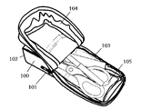
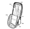
図1、図3及び図4に示すように、本発明が提供する実施例1の容器は、ペン等の文房具の収納装置として、少なくとも第1姿勢と第2姿勢の状態で使用可能である。例えば、図3及び図4に示すように、該実施例1の容器は、それぞれに水平状態(第1姿勢)及び垂直状態(第2姿勢)でペントレー及びペンスタンドとして使用される。 As shown in FIGS. 1, 3, and 4, the container according to the first embodiment provided by the present invention can be used in a state of at least a first posture and a second posture as a storage device for a stationery such as a pen. For example, as shown in FIGS. 3 and 4, the container of Example 1 is used as a pen tray and a pen stand in a horizontal state (first posture) and a vertical state (second posture), respectively.
また、図に示すように、本実施例1は本体部100と蓋部104を備え、本体部100は第1底面部101、第2底面部102、開口部103等の構造を有する。
As shown in the figure, the first embodiment includes a
具体的には、図3に示すように、第1底面部101は容器自体が第1姿勢の状態で使用される場合、容器を自立(自体で立て)させる底面を構成し、即ち、容器を該第1底面部101を介してデスクなどの容器載置平面(支持平面)に自立させることができる。また、第1底面部101は容器の長手方向に沿って延びる。
Specifically, as shown in FIG. 3, when the container itself is used in the first posture, the first
図4に示すように、第2底面部102は容器自体が第2姿勢の状態で使用される場合、容器を自立させる底面を構成し、且つ該第2底面部102は第1底面部101と交わるように広がり、即ち、容器を該第2底面部102を介してデスクなどの載置平面に自立させることができる。第1底面部101と第2底面部102との交わる角度について、特に限定されず、上記機能を実現可能な任意の角度であってもよく、90度で交わるのが好ましい。
As shown in FIG. 4, when the container itself is used in the second posture, the second
第1底面部101と第2底面部102との間の接続方式として、両者の間は直接接続されても間接的に接続されてもよい。一つの好もしい接続方式として、例えば、両者をテーパ部(傾斜部)を介して接続されてもよく、曲率を有する面を介して接続されてもよい。
As a connection method between the 1st
開口部103は第1底面部101の内側に位置し、且つ第1底面部101のうち第2底面部102とは反対側の端部105を含む部分が第1底面部101とは反対側に向けて開放されるように開口した(即ち、図3、4に示すように、蓋部104は外部に向けて折る。また、内部に向けて折り込むこともできる)。蓋部104は開口部103の開閉に用いられ、開口部103に被覆されることができる。
The
これにより、本実施例1はペントレー位置、及びペンスタンド位置の二つの位置に使用され得る。ただし、本発明は文房具に限らず、化粧品又は他の種類の小物等の収容容器として使用可能であり、ペントレーよりもっと広い範囲で使用され得る。 Thus, the first embodiment can be used at two positions, a pen tray position and a pen stand position. However, the present invention is not limited to stationery but can be used as a container for cosmetics or other types of accessories, and can be used in a wider range than a pen tray.
上記第1底面部101と第2底面部102は、直方体形状又は立方体形状の本実施例の二つの面に限定されるものではなく、最も幅広い概念に理解されるべきものである。即ち、閉じた状態における容器の形状は、直方体であってもよく、立方体であってもよい。また、第1底面部101は比較的に大きく、その長手方向が本実施例1の長手方向と一致する。
The first
また、蓋部104は、例えば図1、図3及び図4に示す実施例1のように一体であってもよく、例えば図2に示す実施例2のように二つ係止部1081、1082によって複数の部分に分割されたものであってもよい。また、例えば図5に示す実施例3のように、蓋部104は観音開き構造のように、ドア1041、ドア1042及び両者を接続する係止構造1040を備える。ドア1041とドア1042とは、中央から両側に開けられる。二つのドアを係止する構造は、係止構造1040に限定されず、例えば、ドアと本体部との接続箇所に設けられたマグネットまたは面ファスナー等の他の構造であってもよい。係止機能を実現すればよい。
Further, the
図3、図4に示すように、いずれの開口部103も蓋部104が第2底面部102側に移動することで開けられる。即ち、開口部103を開ける時に、蓋部104を移動すればよい。
As shown in FIGS. 3 and 4, any
開口部103は、蓋部104を前記第2底面部102側に移動させることで開けられることを特徴とする。移動の方式として、図3、4のように蓋部104を容器外部に向けて折り出してもよい。勿論、蓋部104を容器内部に折り込んでもよい。何れもペンスタンド、ペントレーとして使用する効果に影響を与えない。
The opening 103 can be opened by moving the
更に、図1に示すように、本体部100は、第1底面部101のうちの第2底面部102側の部分と対向している対向部106をさらに備える。即ち、蓋部104と対向部106とは、第1底面部101の同一側に位置する。蓋部104は、連結部107を介して対向部106と連結されており、開口部103は、蓋部104と対向部106との間に設けられる連結部107を基点に往復回動することで開閉される。蓋部と対向部との連結部は、蓋部の下端部であってもよく、対向部の上端部であってもよい。実際には、連結部が設けられなくてもよい。すなわち、蓋部と対向部とが一体である場合でも、本発明は両姿勢においてそれぞれペントレーとペンスタンドとして機能可能である。
Furthermore, as shown in FIG. 1, the
また、第2底面部102側に折られる蓋部の一部は、同一高度位置において第2底面部と同一平面に構成しており、例えば、第2底面部102側に折られる蓋部の一部と第2底面部102との何れも容器の支持面に位置する。この時、容器をペンスタンドとして使用する場合の安定度を高めることができる。勿論、折られた蓋部の一部は異なる高度に位置してもよい。
In addition, a part of the lid portion folded to the second
開口部103が開いた状態で、蓋部104と対向部106との間に、固定部(未図示)をさらに備えてもよい。固定部は、折られた蓋部104と対向部106との固定に用いられ、容器の載置安定度をさらに高める。一つ好ましい実施形態として、該固定部は、前記連結部107以外の位置に設けられている。固定部として、凹凸係合の構造であってもよい。蓋部104と対向部106とのうちの一方には、凸部が設けられており、他方には、前記凸部に係合する凹部が設けられる。また、蓋部104と対向部106とのそれぞれに設けられる面ファスナーであってもよく、蓋部104と対向部106とのそれぞれに設けられるマグネットであってもよい。すなわち、当業者が容易に想到できる各種の周知ファスナー(fastner)であってもよい。
A fixing portion (not shown) may be further provided between the
無論、上記固定部の構成部材として、必ず蓋部と対向部とに設けられなくてもよい。例えば、折られた蓋部を固定さえできれば、蓋部に設けられた紐状物と第1底面部の両側(対向部両側の位置)における前記紐状物と結ぶ係合部とからなる固定部であってもよい。 Of course, as a component member of the fixing portion, it is not always necessary to provide the lid portion and the facing portion. For example, as long as the folded lid portion can be fixed, the fixing portion is composed of a string-like object provided on the lid portion and an engagement portion that connects the string-like object on both sides of the first bottom surface portion (positions on opposite sides). It may be.
蓋部104の位置等を限定するために、本実施例1は、蓋部104を本体部の開口部103に対して固定および開放させるための係止部をさらに備えた。係止部として、蓋部104と開口部103とそれぞれに連結されて設けられたファスナーであってもよく、それらに設けられた磁石又は面ファスナーであってもよい。また、係止部の設定位置について、第2底面部から離れるほど第1底面部側に近づくようになる。即ち、第2底面部から離れるほど第1底面部側に近づく位置に設けられる。つまり、蓋部104と開口部103は傾斜設置の係止部によって連結して固定される。
In order to limit the position and the like of the
本発明の別の実施例として、図2に示すように、二つの係止部の設定位置が示され、即ち、何れも本体部100の開口部103と蓋部104との間に設けられ、蓋部104の固定に用いられる係止部1081、1082である。つまり、係止部1081と係止部1082にある箇所において、何れも開きまたは係止でき、本実施例1を異なる容器として用いることができる。
As another embodiment of the present invention, as shown in FIG. 2, the setting positions of the two locking portions are shown, i.e., both are provided between the
好ましい実施例として、係止部は図2に示す係止部1082のように設けられることができる。即ち、係止部が第2底面部102から離れるほど第1底面部101に近づくように設けられる容器は、主にペンスタンド(第1姿勢)として使用される。
As a preferred embodiment, the locking portion can be provided as a
他の好ましい実施例として、係止部は図2に示す係止部1081のように設けられることができる。即ち、係止部が対向部106にある面に殆ど平行し、つまり、第1底面部101にある面に平行する。この係止部1081は、対向部106側の近くに設けられることが好ましい。このように設けられる容器は、主にペントレー(第2姿勢)として使用される。
As another preferred embodiment, the locking portion can be provided as a
無論、同時に係止部1081、1082を設定してもよい。これにより、ペンスタンドとペントレーの両機能を有することができる。
Of course, the locking
この時、図2に示す実施例2の蓋部104は2つの部分を有するため、二つの共通の開口部を形成することができる。ただし、二つの共通の開口部であっても、第1姿勢と第2姿勢においてその中の一つの共通の開口部を共用することができる。
At this time, since the
更に、係止部1081、係止部1082はファスナーであってもよく、磁石、貼付けシート等であってもよい。本体部100および蓋部104の主な材料は、布であることが好ましい。プラスチック、キャンバス、ポリエステル等を使ってもよい。柔軟性を有する材料が好ましい。
Further, the locking
本体部100及び蓋部104は、複数層の材料からなってもよい。また、層と層との間にウレタンシートが挟むことで、容器をある程度の硬度を有して容易に立てせることができる。
The
また、主体部100の開口部103を閉じる時に、蓋部104は直方体状となる。これは、蓋部104が厳密な意味での直方体である意味ではなく、平面視又は側面視の場合、その全体が直方体に近いものであってもよい。また、その形状として、概ね直方体形状であればよい。全ての面は、何れも標準の長方形である必要がない。例えば、長方形の頂点部分(コーナー部)が丸みを帯びた形状となっていてもよい。また、面と面の間は、なだらかに湾曲した面を介して繋がるように構成されていてもよい。
Further, when the
更に、蓋部の内側に消しゴムのような小物の収容に用いられる小さいポケットが設けられてもよい。 Furthermore, a small pocket used for accommodating small items such as an eraser may be provided inside the lid.
技術常識から、本発明は、本発明の主旨又は必要な特徴を逸脱しない範囲で他の実施例によっても実現できることが分かる。従って、上記開示された実施例は唯一のものではなく、ただの例に過ぎない。本発明の範囲内又は本発明の範囲内に均等する変更は、何れも本発明に含まれる。 From the common general technical knowledge, it can be understood that the present invention can be realized by other embodiments without departing from the spirit or necessary features of the present invention. Accordingly, the disclosed embodiments are not the only and are merely examples. Any change within the scope of the present invention or equivalent to the scope of the present invention is included in the present invention.
Claims (12)
前記第1姿勢の状態で前記容器を自立させる底を構成する第1底面部と、前記第2姿勢の状態で前記容器を自立させる底を構成しており前記第1底面部と交わるように広がった第2底面部と、前記第1底面部のうち前記第2底面部側とは反対側の端部を含む部分が前記第1底面部側とは反対側に向けて開放されるように開口した開口部と、を有する本体部と、
前記開口部を開閉可能な蓋部と、を備え、
前記開口部は、前記第1姿勢と前記第2姿勢で共通の開口部である、
ことを特徴とする容器。 A container used for storing objects in at least two postures of a first posture and a second posture,
A first bottom surface portion that constitutes a bottom that allows the container to stand independently in the state of the first posture, and a bottom that constitutes a bottom that allows the container to stand independently in the state of the second posture, and extends so as to intersect the first bottom surface portion. The second bottom surface portion and the portion of the first bottom surface portion including the end opposite to the second bottom surface portion side are opened toward the side opposite to the first bottom surface portion side. A main body having an opening,
A lid that can open and close the opening,
The opening is a common opening in the first posture and the second posture.
A container characterized by that.
ことを特徴とする請求項1に記載の容器。 The opening is opened by moving the lid toward the second bottom surface,
The container according to claim 1.
前記蓋部は、前記対向部と連結されており、
前記開口部は、前記蓋部と前記対向部との連結部を基点に前記第1底面部側とは反対側に回動することで開けられ、
前記連結部は、前記蓋部と前記対向部との間に設けられている、
ことを特徴とする請求項2に記載の容器。 The main body portion further includes a facing portion facing a portion of the first bottom surface portion on the second bottom surface portion side,
The lid portion is connected to the facing portion,
The opening is opened by rotating to the opposite side of the first bottom surface portion side with the connecting portion between the lid portion and the facing portion as a base point,
The connecting portion is provided between the lid portion and the facing portion.
The container according to claim 2.
前記固定部は、前記連結部以外の位置に設けられている、
ことを特徴とする請求項3に記載の容器。 In the state in which the opening is open, it further comprises a fixing part for fixing the lid part and the facing part,
The fixing portion is provided at a position other than the connecting portion.
The container according to claim 3.
ことを特徴とする請求項1から4のいずれか1項に記載の容器。 It is connected to each of the opening and the lid, and further includes a locking portion for fixing and opening the lid with respect to the opening.
The container according to any one of claims 1 to 4, characterized in that:
ことを特徴とする請求項5に記載の容器。 The locking portion comes closer to the first bottom surface portion as the distance from the second bottom surface portion increases.
The container according to claim 5.
ことを特徴とする請求項5に記載の容器。 The locking portion is a fastener.
The container according to claim 5.
ことを特徴とする請求項1から4のいずれか1項に記載の容器。 The material of the main body portion and the lid portion includes a cloth,
The container according to any one of claims 1 to 4, characterized in that:
前記第1底面部と前記第2底面部とは直交する、
ことを特徴とする請求項1から4のいずれか1項に記載の容器。 The first bottom surface portion extends along the longitudinal direction of the container,
The first bottom surface portion and the second bottom surface portion are orthogonal to each other.
The container according to any one of claims 1 to 4, characterized in that:
ことを特徴とする請求項1から4のいずれか1項に記載の容器。 In the state where the lid portion closes the opening of the main body portion, it is a rectangular parallelepiped shape.
The container according to any one of claims 1 to 4, characterized in that:
ことを特徴とする請求項1から4のいずれか1項に記載の容器。 The object is a stationery or a cosmetic,
The container according to any one of claims 1 to 4, characterized in that:
前記第2姿勢では直立のペンスタンドである、
ことを特徴とする請求項11に記載の容器。 In the first posture, it is a pen tray lying down,
In the second posture, it is an upright pen stand,
The container according to claim 11.
Priority Applications (1)
| Application Number | Priority Date | Filing Date | Title |
|---|---|---|---|
| JP2022000235A JP2022060211A (en) | 2016-04-14 | 2022-01-04 | container |
Applications Claiming Priority (2)
| Application Number | Priority Date | Filing Date | Title |
|---|---|---|---|
| CN201620312946.6 | 2016-04-14 | ||
| CN201620312946.6U CN205585535U (en) | 2016-04-14 | 2016-04-14 | Container |
Related Child Applications (1)
| Application Number | Title | Priority Date | Filing Date |
|---|---|---|---|
| JP2022000235A Division JP2022060211A (en) | 2016-04-14 | 2022-01-04 | container |
Publications (1)
| Publication Number | Publication Date |
|---|---|
| JP2017200570A true JP2017200570A (en) | 2017-11-09 |
Family
ID=56921934
Family Applications (2)
| Application Number | Title | Priority Date | Filing Date |
|---|---|---|---|
| JP2017079538A Ceased JP2017200570A (en) | 2016-04-14 | 2017-04-13 | container |
| JP2022000235A Pending JP2022060211A (en) | 2016-04-14 | 2022-01-04 | container |
Family Applications After (1)
| Application Number | Title | Priority Date | Filing Date |
|---|---|---|---|
| JP2022000235A Pending JP2022060211A (en) | 2016-04-14 | 2022-01-04 | container |
Country Status (2)
| Country | Link |
|---|---|
| JP (2) | JP2017200570A (en) |
| CN (1) | CN205585535U (en) |
Cited By (4)
| Publication number | Priority date | Publication date | Assignee | Title |
|---|---|---|---|---|
| WO2018216488A1 (en) * | 2017-05-24 | 2018-11-29 | 株式会社大阪クリップ | Freestanding pen case |
| JP2020000741A (en) * | 2018-06-29 | 2020-01-09 | コクヨ株式会社 | container |
| JP2020055222A (en) * | 2018-10-02 | 2020-04-09 | 高波クリエイト株式会社 | Pen case |
| JP2022168290A (en) * | 2018-08-21 | 2022-11-04 | コクヨ株式会社 | container |
Citations (3)
| Publication number | Priority date | Publication date | Assignee | Title |
|---|---|---|---|---|
| JPS61181785U (en) * | 1985-05-04 | 1986-11-13 | ||
| US20050092648A1 (en) * | 2003-07-09 | 2005-05-05 | Asia Atlantic Trading Development | Container forming a presenter in open position |
| JP2008131964A (en) * | 2006-11-27 | 2008-06-12 | Sakura Color Prod Corp | Calligraphy case |
-
2016
- 2016-04-14 CN CN201620312946.6U patent/CN205585535U/en not_active Expired - Lifetime
-
2017
- 2017-04-13 JP JP2017079538A patent/JP2017200570A/en not_active Ceased
-
2022
- 2022-01-04 JP JP2022000235A patent/JP2022060211A/en active Pending
Patent Citations (3)
| Publication number | Priority date | Publication date | Assignee | Title |
|---|---|---|---|---|
| JPS61181785U (en) * | 1985-05-04 | 1986-11-13 | ||
| US20050092648A1 (en) * | 2003-07-09 | 2005-05-05 | Asia Atlantic Trading Development | Container forming a presenter in open position |
| JP2008131964A (en) * | 2006-11-27 | 2008-06-12 | Sakura Color Prod Corp | Calligraphy case |
Cited By (7)
| Publication number | Priority date | Publication date | Assignee | Title |
|---|---|---|---|---|
| WO2018216488A1 (en) * | 2017-05-24 | 2018-11-29 | 株式会社大阪クリップ | Freestanding pen case |
| US11330880B2 (en) | 2017-05-24 | 2022-05-17 | Osaka Clip Co., Ltd | Self-standing housing body |
| JP2020000741A (en) * | 2018-06-29 | 2020-01-09 | コクヨ株式会社 | container |
| JP7200514B2 (en) | 2018-06-29 | 2023-01-10 | コクヨ株式会社 | container |
| JP2022168290A (en) * | 2018-08-21 | 2022-11-04 | コクヨ株式会社 | container |
| JP7416158B2 (en) | 2018-08-21 | 2024-01-17 | コクヨ株式会社 | container |
| JP2020055222A (en) * | 2018-10-02 | 2020-04-09 | 高波クリエイト株式会社 | Pen case |
Also Published As
| Publication number | Publication date |
|---|---|
| JP2022060211A (en) | 2022-04-14 |
| CN205585535U (en) | 2016-09-21 |
Similar Documents
| Publication | Publication Date | Title |
|---|---|---|
| JP2022060211A (en) | container | |
| US9938037B2 (en) | Package with flip-open closure | |
| US11330880B2 (en) | Self-standing housing body | |
| US20200187616A1 (en) | Multi-functional storage box | |
| CN108567212B (en) | Small article container | |
| US10293756B1 (en) | Collapsible article organizer for airliner use | |
| US5350061A (en) | Container systems for school supplies | |
| JP3976874B2 (en) | Case | |
| US8678217B2 (en) | Activity and storage case | |
| JP3234338U (en) | Storage case | |
| JP3219719U (en) | accessory case | |
| JP3228768U (en) | Stand type pen case | |
| JP3180127U (en) | Desktop divider | |
| KR200454820Y1 (en) | Portable Painting Wallet | |
| JP3242459U (en) | Partition plate and case containing the partition plate | |
| US12404070B2 (en) | Packing box | |
| CN207329048U (en) | Container structure made of paper | |
| JP6224875B1 (en) | Writing instrument case | |
| CN207679015U (en) | A kind of storage box | |
| CN201270889Y (en) | Folding containing case | |
| CN215852729U (en) | Packing box | |
| JP3232470U (en) | Tissue box and storage case for small items | |
| CN213443763U (en) | Packing box (Chinese character' jiangsu | |
| JP2000142700A (en) | Storage container | |
| JP7354656B2 (en) | Small items storage case |
Legal Events
| Date | Code | Title | Description |
|---|---|---|---|
| A521 | Request for written amendment filed |
Free format text: JAPANESE INTERMEDIATE CODE: A523 Effective date: 20170630 |
|
| A621 | Written request for application examination |
Free format text: JAPANESE INTERMEDIATE CODE: A621 Effective date: 20200312 |
|
| A977 | Report on retrieval |
Free format text: JAPANESE INTERMEDIATE CODE: A971007 Effective date: 20210209 |
|
| A131 | Notification of reasons for refusal |
Free format text: JAPANESE INTERMEDIATE CODE: A131 Effective date: 20210224 |
|
| A521 | Request for written amendment filed |
Free format text: JAPANESE INTERMEDIATE CODE: A523 Effective date: 20210426 |
|
| A131 | Notification of reasons for refusal |
Free format text: JAPANESE INTERMEDIATE CODE: A131 Effective date: 20210713 |
|
| A521 | Request for written amendment filed |
Free format text: JAPANESE INTERMEDIATE CODE: A523 Effective date: 20210909 |
|
| A02 | Decision of refusal |
Free format text: JAPANESE INTERMEDIATE CODE: A02 Effective date: 20211005 |
|
| A521 | Request for written amendment filed |
Free format text: JAPANESE INTERMEDIATE CODE: A523 Effective date: 20220104 |
|
| C60 | Trial request (containing other claim documents, opposition documents) |
Free format text: JAPANESE INTERMEDIATE CODE: C60 Effective date: 20220104 |
|
| A911 | Transfer to examiner for re-examination before appeal (zenchi) |
Free format text: JAPANESE INTERMEDIATE CODE: A911 Effective date: 20220113 |
|
| C21 | Notice of transfer of a case for reconsideration by examiners before appeal proceedings |
Free format text: JAPANESE INTERMEDIATE CODE: C21 Effective date: 20220118 |
|
| A912 | Re-examination (zenchi) completed and case transferred to appeal board |
Free format text: JAPANESE INTERMEDIATE CODE: A912 Effective date: 20220204 |
|
| C211 | Notice of termination of reconsideration by examiners before appeal proceedings |
Free format text: JAPANESE INTERMEDIATE CODE: C211 Effective date: 20220208 |
|
| C22 | Notice of designation (change) of administrative judge |
Free format text: JAPANESE INTERMEDIATE CODE: C22 Effective date: 20220614 |
|
| C22 | Notice of designation (change) of administrative judge |
Free format text: JAPANESE INTERMEDIATE CODE: C22 Effective date: 20220802 |
|
| C13 | Notice of reasons for refusal |
Free format text: JAPANESE INTERMEDIATE CODE: C13 Effective date: 20221004 |
|
| A521 | Request for written amendment filed |
Free format text: JAPANESE INTERMEDIATE CODE: A523 Effective date: 20221114 |
|
| C22 | Notice of designation (change) of administrative judge |
Free format text: JAPANESE INTERMEDIATE CODE: C22 Effective date: 20221213 |
|
| C23 | Notice of termination of proceedings |
Free format text: JAPANESE INTERMEDIATE CODE: C23 Effective date: 20230110 |
|
| C03 | Trial/appeal decision taken |
Free format text: JAPANESE INTERMEDIATE CODE: C03 Effective date: 20230207 |
|
| C30A | Notification sent |
Free format text: JAPANESE INTERMEDIATE CODE: C3012 Effective date: 20230207 |
|
| A601 | Written request for extension of time |
Free format text: JAPANESE INTERMEDIATE CODE: A601 Effective date: 20230301 |
|
| A045 | Written measure of dismissal of application [lapsed due to lack of payment] |
Free format text: JAPANESE INTERMEDIATE CODE: A045 Effective date: 20230627 |