JP2017200676A - Exhaust gas purification catalyst of internal combustion engine - Google Patents
Exhaust gas purification catalyst of internal combustion engine Download PDFInfo
- Publication number
- JP2017200676A JP2017200676A JP2016092555A JP2016092555A JP2017200676A JP 2017200676 A JP2017200676 A JP 2017200676A JP 2016092555 A JP2016092555 A JP 2016092555A JP 2016092555 A JP2016092555 A JP 2016092555A JP 2017200676 A JP2017200676 A JP 2017200676A
- Authority
- JP
- Japan
- Prior art keywords
- catalyst
- layer
- exhaust gas
- upstream
- downstream
- Prior art date
- Legal status (The legal status is an assumption and is not a legal conclusion. Google has not performed a legal analysis and makes no representation as to the accuracy of the status listed.)
- Pending
Links
Images


Classifications
-
- B—PERFORMING OPERATIONS; TRANSPORTING
- B01—PHYSICAL OR CHEMICAL PROCESSES OR APPARATUS IN GENERAL
- B01D—SEPARATION
- B01D53/00—Separation of gases or vapours; Recovering vapours of volatile solvents from gases; Chemical or biological purification of waste gases, e.g. engine exhaust gases, smoke, fumes, flue gases, aerosols
- B01D53/34—Chemical or biological purification of waste gases
- B01D53/92—Chemical or biological purification of waste gases of engine exhaust gases
- B01D53/94—Chemical or biological purification of waste gases of engine exhaust gases by catalytic processes
- B01D53/9445—Simultaneously removing carbon monoxide, hydrocarbons or nitrogen oxides making use of three-way catalysts [TWC] or four-way-catalysts [FWC]
- B01D53/945—Simultaneously removing carbon monoxide, hydrocarbons or nitrogen oxides making use of three-way catalysts [TWC] or four-way-catalysts [FWC] characterised by a specific catalyst
-
- B—PERFORMING OPERATIONS; TRANSPORTING
- B01—PHYSICAL OR CHEMICAL PROCESSES OR APPARATUS IN GENERAL
- B01J—CHEMICAL OR PHYSICAL PROCESSES, e.g. CATALYSIS OR COLLOID CHEMISTRY; THEIR RELEVANT APPARATUS
- B01J37/00—Processes, in general, for preparing catalysts; Processes, in general, for activation of catalysts
- B01J37/02—Impregnation, coating or precipitation
- B01J37/024—Multiple impregnation or coating
- B01J37/0244—Coatings comprising several layers
-
- B—PERFORMING OPERATIONS; TRANSPORTING
- B01—PHYSICAL OR CHEMICAL PROCESSES OR APPARATUS IN GENERAL
- B01D—SEPARATION
- B01D53/00—Separation of gases or vapours; Recovering vapours of volatile solvents from gases; Chemical or biological purification of waste gases, e.g. engine exhaust gases, smoke, fumes, flue gases, aerosols
- B01D53/34—Chemical or biological purification of waste gases
- B01D53/92—Chemical or biological purification of waste gases of engine exhaust gases
- B01D53/94—Chemical or biological purification of waste gases of engine exhaust gases by catalytic processes
- B01D53/944—Simultaneously removing carbon monoxide, hydrocarbons or carbon making use of oxidation catalysts
-
- B—PERFORMING OPERATIONS; TRANSPORTING
- B01—PHYSICAL OR CHEMICAL PROCESSES OR APPARATUS IN GENERAL
- B01D—SEPARATION
- B01D53/00—Separation of gases or vapours; Recovering vapours of volatile solvents from gases; Chemical or biological purification of waste gases, e.g. engine exhaust gases, smoke, fumes, flue gases, aerosols
- B01D53/34—Chemical or biological purification of waste gases
- B01D53/92—Chemical or biological purification of waste gases of engine exhaust gases
- B01D53/94—Chemical or biological purification of waste gases of engine exhaust gases by catalytic processes
- B01D53/9445—Simultaneously removing carbon monoxide, hydrocarbons or nitrogen oxides making use of three-way catalysts [TWC] or four-way-catalysts [FWC]
-
- B—PERFORMING OPERATIONS; TRANSPORTING
- B01—PHYSICAL OR CHEMICAL PROCESSES OR APPARATUS IN GENERAL
- B01J—CHEMICAL OR PHYSICAL PROCESSES, e.g. CATALYSIS OR COLLOID CHEMISTRY; THEIR RELEVANT APPARATUS
- B01J23/00—Catalysts comprising metals or metal oxides or hydroxides, not provided for in group B01J21/00
- B01J23/002—Mixed oxides other than spinels, e.g. perovskite
-
- B—PERFORMING OPERATIONS; TRANSPORTING
- B01—PHYSICAL OR CHEMICAL PROCESSES OR APPARATUS IN GENERAL
- B01J—CHEMICAL OR PHYSICAL PROCESSES, e.g. CATALYSIS OR COLLOID CHEMISTRY; THEIR RELEVANT APPARATUS
- B01J23/00—Catalysts comprising metals or metal oxides or hydroxides, not provided for in group B01J21/00
- B01J23/38—Catalysts comprising metals or metal oxides or hydroxides, not provided for in group B01J21/00 of noble metals
- B01J23/40—Catalysts comprising metals or metal oxides or hydroxides, not provided for in group B01J21/00 of noble metals of the platinum group metals
- B01J23/42—Platinum
-
- B—PERFORMING OPERATIONS; TRANSPORTING
- B01—PHYSICAL OR CHEMICAL PROCESSES OR APPARATUS IN GENERAL
- B01J—CHEMICAL OR PHYSICAL PROCESSES, e.g. CATALYSIS OR COLLOID CHEMISTRY; THEIR RELEVANT APPARATUS
- B01J23/00—Catalysts comprising metals or metal oxides or hydroxides, not provided for in group B01J21/00
- B01J23/38—Catalysts comprising metals or metal oxides or hydroxides, not provided for in group B01J21/00 of noble metals
- B01J23/40—Catalysts comprising metals or metal oxides or hydroxides, not provided for in group B01J21/00 of noble metals of the platinum group metals
- B01J23/44—Palladium
-
- B—PERFORMING OPERATIONS; TRANSPORTING
- B01—PHYSICAL OR CHEMICAL PROCESSES OR APPARATUS IN GENERAL
- B01J—CHEMICAL OR PHYSICAL PROCESSES, e.g. CATALYSIS OR COLLOID CHEMISTRY; THEIR RELEVANT APPARATUS
- B01J23/00—Catalysts comprising metals or metal oxides or hydroxides, not provided for in group B01J21/00
- B01J23/38—Catalysts comprising metals or metal oxides or hydroxides, not provided for in group B01J21/00 of noble metals
- B01J23/40—Catalysts comprising metals or metal oxides or hydroxides, not provided for in group B01J21/00 of noble metals of the platinum group metals
- B01J23/46—Ruthenium, rhodium, osmium or iridium
- B01J23/464—Rhodium
-
- B—PERFORMING OPERATIONS; TRANSPORTING
- B01—PHYSICAL OR CHEMICAL PROCESSES OR APPARATUS IN GENERAL
- B01J—CHEMICAL OR PHYSICAL PROCESSES, e.g. CATALYSIS OR COLLOID CHEMISTRY; THEIR RELEVANT APPARATUS
- B01J23/00—Catalysts comprising metals or metal oxides or hydroxides, not provided for in group B01J21/00
- B01J23/38—Catalysts comprising metals or metal oxides or hydroxides, not provided for in group B01J21/00 of noble metals
- B01J23/54—Catalysts comprising metals or metal oxides or hydroxides, not provided for in group B01J21/00 of noble metals combined with metals, oxides or hydroxides provided for in groups B01J23/02 - B01J23/36
- B01J23/56—Platinum group metals
- B01J23/63—Platinum group metals with rare earths or actinides
-
- B—PERFORMING OPERATIONS; TRANSPORTING
- B01—PHYSICAL OR CHEMICAL PROCESSES OR APPARATUS IN GENERAL
- B01J—CHEMICAL OR PHYSICAL PROCESSES, e.g. CATALYSIS OR COLLOID CHEMISTRY; THEIR RELEVANT APPARATUS
- B01J35/00—Catalysts, in general, characterised by their form or physical properties
- B01J35/19—Catalysts containing parts with different compositions
-
- F—MECHANICAL ENGINEERING; LIGHTING; HEATING; WEAPONS; BLASTING
- F01—MACHINES OR ENGINES IN GENERAL; ENGINE PLANTS IN GENERAL; STEAM ENGINES
- F01N—GAS-FLOW SILENCERS OR EXHAUST APPARATUS FOR MACHINES OR ENGINES IN GENERAL; GAS-FLOW SILENCERS OR EXHAUST APPARATUS FOR INTERNAL-COMBUSTION ENGINES
- F01N3/00—Exhaust or silencing apparatus having means for purifying, rendering innocuous, or otherwise treating exhaust
- F01N3/08—Exhaust or silencing apparatus having means for purifying, rendering innocuous, or otherwise treating exhaust for rendering innocuous
- F01N3/10—Exhaust or silencing apparatus having means for purifying, rendering innocuous, or otherwise treating exhaust for rendering innocuous by thermal or catalytic conversion of noxious components of exhaust
- F01N3/101—Three-way catalysts
-
- B—PERFORMING OPERATIONS; TRANSPORTING
- B01—PHYSICAL OR CHEMICAL PROCESSES OR APPARATUS IN GENERAL
- B01D—SEPARATION
- B01D2255/00—Catalysts
- B01D2255/10—Noble metals or compounds thereof
- B01D2255/102—Platinum group metals
- B01D2255/1021—Platinum
-
- B—PERFORMING OPERATIONS; TRANSPORTING
- B01—PHYSICAL OR CHEMICAL PROCESSES OR APPARATUS IN GENERAL
- B01D—SEPARATION
- B01D2255/00—Catalysts
- B01D2255/10—Noble metals or compounds thereof
- B01D2255/102—Platinum group metals
- B01D2255/1023—Palladium
-
- B—PERFORMING OPERATIONS; TRANSPORTING
- B01—PHYSICAL OR CHEMICAL PROCESSES OR APPARATUS IN GENERAL
- B01D—SEPARATION
- B01D2255/00—Catalysts
- B01D2255/10—Noble metals or compounds thereof
- B01D2255/102—Platinum group metals
- B01D2255/1025—Rhodium
-
- B—PERFORMING OPERATIONS; TRANSPORTING
- B01—PHYSICAL OR CHEMICAL PROCESSES OR APPARATUS IN GENERAL
- B01D—SEPARATION
- B01D2255/00—Catalysts
- B01D2255/40—Mixed oxides
- B01D2255/407—Zr-Ce mixed oxides
-
- B—PERFORMING OPERATIONS; TRANSPORTING
- B01—PHYSICAL OR CHEMICAL PROCESSES OR APPARATUS IN GENERAL
- B01D—SEPARATION
- B01D2255/00—Catalysts
- B01D2255/90—Physical characteristics of catalysts
- B01D2255/902—Multilayered catalyst
- B01D2255/9022—Two layers
-
- B—PERFORMING OPERATIONS; TRANSPORTING
- B01—PHYSICAL OR CHEMICAL PROCESSES OR APPARATUS IN GENERAL
- B01D—SEPARATION
- B01D2255/00—Catalysts
- B01D2255/90—Physical characteristics of catalysts
- B01D2255/903—Multi-zoned catalysts
- B01D2255/9032—Two zones
-
- B—PERFORMING OPERATIONS; TRANSPORTING
- B01—PHYSICAL OR CHEMICAL PROCESSES OR APPARATUS IN GENERAL
- B01D—SEPARATION
- B01D2255/00—Catalysts
- B01D2255/90—Physical characteristics of catalysts
- B01D2255/908—O2-storage component incorporated in the catalyst
-
- B—PERFORMING OPERATIONS; TRANSPORTING
- B01—PHYSICAL OR CHEMICAL PROCESSES OR APPARATUS IN GENERAL
- B01D—SEPARATION
- B01D2258/00—Sources of waste gases
- B01D2258/01—Engine exhaust gases
- B01D2258/012—Diesel engines and lean burn gasoline engines
-
- B—PERFORMING OPERATIONS; TRANSPORTING
- B01—PHYSICAL OR CHEMICAL PROCESSES OR APPARATUS IN GENERAL
- B01J—CHEMICAL OR PHYSICAL PROCESSES, e.g. CATALYSIS OR COLLOID CHEMISTRY; THEIR RELEVANT APPARATUS
- B01J35/00—Catalysts, in general, characterised by their form or physical properties
- B01J35/50—Catalysts, in general, characterised by their form or physical properties characterised by their shape or configuration
- B01J35/56—Foraminous structures having flow-through passages or channels, e.g. grids or three-dimensional [3D] monoliths
-
- F—MECHANICAL ENGINEERING; LIGHTING; HEATING; WEAPONS; BLASTING
- F01—MACHINES OR ENGINES IN GENERAL; ENGINE PLANTS IN GENERAL; STEAM ENGINES
- F01N—GAS-FLOW SILENCERS OR EXHAUST APPARATUS FOR MACHINES OR ENGINES IN GENERAL; GAS-FLOW SILENCERS OR EXHAUST APPARATUS FOR INTERNAL-COMBUSTION ENGINES
- F01N2510/00—Surface coverings
- F01N2510/06—Surface coverings for exhaust purification, e.g. catalytic reaction
- F01N2510/068—Surface coverings for exhaust purification, e.g. catalytic reaction characterised by the distribution of the catalytic coatings
- F01N2510/0684—Surface coverings for exhaust purification, e.g. catalytic reaction characterised by the distribution of the catalytic coatings having more than one coating layer, e.g. multi-layered coatings
-
- Y—GENERAL TAGGING OF NEW TECHNOLOGICAL DEVELOPMENTS; GENERAL TAGGING OF CROSS-SECTIONAL TECHNOLOGIES SPANNING OVER SEVERAL SECTIONS OF THE IPC; TECHNICAL SUBJECTS COVERED BY FORMER USPC CROSS-REFERENCE ART COLLECTIONS [XRACs] AND DIGESTS
- Y02—TECHNOLOGIES OR APPLICATIONS FOR MITIGATION OR ADAPTATION AGAINST CLIMATE CHANGE
- Y02T—CLIMATE CHANGE MITIGATION TECHNOLOGIES RELATED TO TRANSPORTATION
- Y02T10/00—Road transport of goods or passengers
- Y02T10/10—Internal combustion engine [ICE] based vehicles
- Y02T10/12—Improving ICE efficiencies
Landscapes
- Chemical & Material Sciences (AREA)
- Engineering & Computer Science (AREA)
- Chemical Kinetics & Catalysis (AREA)
- Materials Engineering (AREA)
- Organic Chemistry (AREA)
- Combustion & Propulsion (AREA)
- Health & Medical Sciences (AREA)
- Analytical Chemistry (AREA)
- Biomedical Technology (AREA)
- Environmental & Geological Engineering (AREA)
- General Chemical & Material Sciences (AREA)
- Oil, Petroleum & Natural Gas (AREA)
- Mechanical Engineering (AREA)
- General Engineering & Computer Science (AREA)
- Toxicology (AREA)
- Catalysts (AREA)
- Exhaust Gas After Treatment (AREA)
- Exhaust Gas Treatment By Means Of Catalyst (AREA)
Abstract
【課題】本発明の少なくとも一つの実施形態は、エンジンオイル由来成分であるリン(P)による被毒の影響が抑制し、エンジンの始動後から高負荷時に排出するNOxを効果的に浄化することを目的とする。【解決手段】内燃機関の排ガス浄化触媒11において、触媒層23は、排ガスの流れに接する第1の触媒層27と、第1の触媒層の基材側表面に形成される第2の触媒層25と、から形成され、第2の触媒層25の排ガス流れに対し上流側を構成する第2の触媒上流層25aに担持される触媒成分、及び第1の触媒層27の排ガス流れに対し下流側を構成する第1の触媒下流層27bに担持される触媒成分は、パラジウム(Pd)と白金(Pt)の少なくとも一方及び酸素吸蔵材(OSC材)を含み、第1の触媒下流層27bに含有されるOSC材量は、第2の触媒上流層25aに含有されるOSC材量より多いことを特徴とする。【選択図】図2At least one embodiment of the present invention suppresses the influence of poisoning caused by phosphorus (P), which is a component derived from engine oil, and effectively purifies NOx discharged at a high load after engine startup. With the goal. In an exhaust gas purification catalyst 11 of an internal combustion engine, a catalyst layer 23 includes a first catalyst layer 27 in contact with a flow of exhaust gas, and a second catalyst layer formed on a substrate side surface of the first catalyst layer. 25, and downstream of the exhaust gas flow of the first catalyst layer 27 and the catalyst component carried on the second catalyst upstream layer 25a constituting the upstream side of the exhaust gas flow of the second catalyst layer 25. The catalyst component supported on the first catalyst downstream layer 27b constituting the side contains at least one of palladium (Pd) and platinum (Pt) and an oxygen storage material (OSC material). The amount of OSC material contained is greater than the amount of OSC material contained in the second catalyst upstream layer 25a. [Selection] Figure 2
Description
本開示は、内燃機関の排ガス浄化触媒に関する。 The present disclosure relates to an exhaust gas purification catalyst for an internal combustion engine.
ガソリンエンジンから排出される排ガスの浄化触媒として、排ガス中の一酸化炭素(CO)、炭化水素(HC)、窒素酸化物(NOx)を同時に酸化と還元を行う三元触媒が用いられている。
この三元触媒は、主に白金(Pt)、パラジウム(Pd)及びロジウム(Rh)を触媒金属として含み、一層の触媒層内に上記3種の触媒金属が混合された触媒、又は触媒層を上層と下層とに分けて、それぞれに触媒金属が分離担持された触媒、又は排ガス流れ方向に対して上流側と下流側とに分けて、それぞれに触媒金属が分離担持された触媒等の種々のタイプの触媒が提案されている。
As a purification catalyst for exhaust gas discharged from a gasoline engine, a three-way catalyst that simultaneously oxidizes and reduces carbon monoxide (CO), hydrocarbon (HC), and nitrogen oxide (NOx) in exhaust gas is used.
This three-way catalyst mainly contains platinum (Pt), palladium (Pd) and rhodium (Rh) as catalyst metals, and a catalyst in which the above three kinds of catalyst metals are mixed in one catalyst layer, or a catalyst layer. Various catalysts such as a catalyst in which a catalyst metal is separately supported on each of the upper layer and a lower layer, or a catalyst in which a catalyst metal is separately supported on each of the upstream side and the downstream side in the exhaust gas flow direction. Types of catalysts have been proposed.
例えば、特許文献1には、飽和炭化水素を含む排ガスを効率よく浄化できるようにする排ガス浄化触媒について示され、排ガス流れ方向上流側には、触媒金属としてPtのみを含む触媒層が設けられ、排ガス流れ方向下流側にはPtを含まないPd及びRhを含む触媒層が設けられ、Ptのみを含む触媒層においては、中心部に設けられるPtの含有量を周縁部より大きくすることが示されている。
For example,
また、特許文献2には、触媒金属の粒成長を抑制することができる排ガス浄化触媒について示され、基材と、基材上に形成され、Pd及びPtの少なくとも1種を含む下触媒層と、Rhを含む上触媒層とを有し、排ガス上流側に上触媒層を含まない領域が設けられ、下触媒層が排ガス上流側の前段下触媒層と排ガス下流側の後段下触媒層からなり、前段下触媒層が酸素吸放出材を含むことが示されている。 Patent Document 2 shows an exhaust gas purifying catalyst capable of suppressing grain growth of catalyst metal, and a base material, and a lower catalyst layer formed on the base material and containing at least one of Pd and Pt. , An upper catalyst layer containing Rh, a region not including the upper catalyst layer is provided on the exhaust gas upstream side, and the lower catalyst layer is composed of a front lower catalyst layer on the exhaust gas upstream side and a rear lower catalyst layer on the exhaust gas downstream side. It is shown that the former lower catalyst layer contains an oxygen storage / release material.
ところで、大気のクリーン化が求められるなか、ガソリンエンジンでは、触媒システムの排ガス浄化性能のさらなる向上が必要である。特に、実環境を考慮すると、エンジン冷態時の排ガス低減が重要な課題である。
この課題への対応として、触媒の早期昇温を狙って、三元触媒をエンジン近接位置に搭載したシステムが検討されている。しかしながら、このようなエンジンの近接位置に触媒を搭載したシステムでは、排気圧力の上昇によって、エンジン性能が低下してしまうという問題もある。したがって、より厳しい排ガス規制に対応し、触媒の圧力損失を抑制するためにも、さらなる触媒性能の向上が求められている。
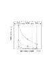
一般に、図9に示すように、貴金属担持量を増大するほど、また、触媒温度が高いほど、排ガス浄化性能は優れる。このため、触媒の昇温過程において、排ガス浄化効率を高めるには、触媒活性成分である貴金属の担持量を増大する手法が用いられるが、コストが極めて高価になるという問題がある。
By the way, while the atmosphere needs to be cleaned, the gasoline engine needs to further improve the exhaust gas purification performance of the catalyst system. In particular, considering the actual environment, reducing exhaust gas when the engine is cold is an important issue.
In response to this problem, a system in which a three-way catalyst is mounted in the vicinity of the engine is being studied with the aim of raising the temperature of the catalyst early. However, in such a system in which a catalyst is mounted at a position close to the engine, there is a problem that engine performance deteriorates due to an increase in exhaust pressure. Therefore, in order to cope with stricter exhaust gas regulations and suppress the pressure loss of the catalyst, further improvement in catalyst performance is required.
In general, as shown in FIG. 9, the exhaust gas purification performance is better as the amount of noble metal supported is increased and the catalyst temperature is higher. For this reason, in order to increase the exhaust gas purification efficiency in the temperature raising process of the catalyst, a method of increasing the amount of the noble metal supported as the catalytic active component is used, but there is a problem that the cost becomes extremely expensive.
一方、エンジン近接位置に触媒を搭載したシステムでは、エンジンから排出されるエンジンオイル由来成分であるリンによる被毒の影響を受けやすく、特に、三元触媒を構成する貴金属及び酸素吸蔵材(以下、OSC材)がその影響を受けやすい。触媒層にリンなどの被毒成分が堆積すると、触媒層中のガス拡散性が低下するため、貴金属と排ガスとの反応性が低下してしまう。また、OSC材にリンが付着するとOSC材の初期構造が変化してその機能が十分発揮できなくなる。OSC材は、セリア−ジルコニア(CeO2−ZrO2)に第3の希土類元素を複合させた酸化物であるが、触媒層中のリン堆積量が多くなると、リンとOSC材中のセリウムが化合し、リン酸セリウム(CePO4)を形成する。これにより,OSC材のCeO2−ZrO2構造が崩れて、初期に有していた酸素吸蔵能力が大幅に低下してしまう。したがって、リン被毒はOSC材の劣化に及ぼす影響が大きい。なお、OSC材は、雰囲気(酸素濃度)変動時に、過剰な酸素を吸蔵して、NOxの還元性能を保持する機能を有する。このため、リン被毒が進行すると、OSC材の機能低下にともない、NOx浄化性能が悪化する。 On the other hand, a system in which a catalyst is mounted in the proximity of the engine is susceptible to poisoning by phosphorus, which is a component derived from engine oil discharged from the engine. OSC material) is easily affected. When poisonous components such as phosphorus are deposited on the catalyst layer, the gas diffusibility in the catalyst layer is lowered, and the reactivity between the noble metal and the exhaust gas is lowered. In addition, when phosphorus adheres to the OSC material, the initial structure of the OSC material changes and the function cannot be fully exhibited. The OSC material is an oxide in which a third rare earth element is combined with ceria-zirconia (CeO 2 —ZrO 2 ). However, when the amount of phosphorus deposited in the catalyst layer increases, the phosphorous and cerium in the OSC material combine. Then, cerium phosphate (CePO 4 ) is formed. As a result, the CeO 2 —ZrO 2 structure of the OSC material collapses, and the oxygen storage capacity that was initially possessed is greatly reduced. Therefore, phosphorus poisoning has a great influence on the deterioration of the OSC material. The OSC material has a function of occluding excess oxygen and maintaining NOx reduction performance when the atmosphere (oxygen concentration) varies. For this reason, when phosphorus poisoning proceeds, the NOx purification performance deteriorates as the function of the OSC material decreases.
上記の特許文献1、2には、基材上にそれぞれ別個の複数の触媒層をコートした排ガス浄化触媒が記載されているが、エンジンオイル由来成分であるリンによる被毒の影響を抑制する技術については開示されていない。また、今後、エンジン冷態時の排ガス低減への対応として触媒の昇温性向上を狙って、触媒配置のエンジンへの近接化が検討される状況下では、触媒の貴金属担持量を極力抑えて、排気圧力の上昇抑制と触媒コストの削減が一層必要とされる。
The
そこで、上記技術的課題に鑑み、本発明の少なくとも一つの実施形態は、エンジンオイル由来成分であるリン、亜鉛、カルシウムなどによる被毒の影響を抑制し、エンジンの始動後から高負荷時に排出する排ガス成分(とくに、NOx)を効果的に浄化する内燃機関の排ガス浄化触媒を提供することを目的とする。 Therefore, in view of the above technical problem, at least one embodiment of the present invention suppresses the influence of poisoning caused by engine oil-derived components such as phosphorus, zinc, calcium, etc., and discharges at high load after engine startup. An object is to provide an exhaust gas purification catalyst for an internal combustion engine that effectively purifies exhaust gas components (particularly NOx).
(1)本発明の少なくとも一実施形態に係る内燃機関の排ガス浄化触媒は、エンジンの排ガス通路に配設され、基材と、該基材の表面に形成された触媒層と、該触媒層に担持された触媒成分とを備える内燃機関の排ガス浄化触媒において、前記触媒層は、排ガス流れに接する第1の触媒層と、前記第1の触媒層の基材側表面に形成される第2の触媒層と、から形成され、前記第2の触媒層の前記排ガス流れに対し上流側を構成する第2の触媒上流層に担持される触媒成分は、パラジウム(Pd)と白金(Pt)の少なくとも一方及び酸素吸蔵材を含み、前記第1の触媒層の前記排ガス流れに対し下流側を構成する第1の触媒下流層に担持される触媒成分は、PdまたはPtの少なく一方及び酸素吸蔵材を含み、前記第1の触媒下流層に含有される前記酸素吸蔵材量は、前記第2の触媒上流層に含有される前記酸素吸蔵材量より多いことを特徴とする。 (1) An exhaust gas purification catalyst for an internal combustion engine according to at least one embodiment of the present invention is disposed in an exhaust gas passage of an engine, and includes a base material, a catalyst layer formed on the surface of the base material, and the catalyst layer. In the exhaust gas purification catalyst for an internal combustion engine comprising a supported catalyst component, the catalyst layer includes a first catalyst layer in contact with the exhaust gas flow, and a second catalyst surface formed on a substrate-side surface of the first catalyst layer. And a catalyst component carried on the second catalyst upstream layer, which is upstream of the exhaust gas flow of the second catalyst layer, is composed of at least palladium (Pd) and platinum (Pt). One of the catalyst components including the oxygen storage material and supported on the first catalyst downstream layer constituting the downstream side of the exhaust gas flow of the first catalyst layer includes at least one of Pd or Pt and the oxygen storage material. And contained in the first catalyst downstream layer The oxygen storage material content that is characterized by more than the oxygen storage material amount contained in the second catalyst upstream layer.
上記構成(1)によれば、第2の触媒上流層に担持される触媒成分は、PdとPtの少なくとも一方及び酸素吸蔵材(OSC材)を含み、第1の触媒下流層に担持される触媒成分は、PdまたはPtの少なくとも一方及びOSC材を含み、第1の触媒下流層に含まれるOSC材量(重量)である含有密度は、第2の触媒上流層に含まれるOSC材量(重量)である含有密度より高く設定することで、リン被毒を抑制し、排ガス浄化性能を向上することができる。 According to the configuration (1), the catalyst component supported on the second catalyst upstream layer includes at least one of Pd and Pt and an oxygen storage material (OSC material), and is supported on the first catalyst downstream layer. The catalyst component includes at least one of Pd or Pt and the OSC material, and the content density, which is the amount (weight) of OSC material contained in the first catalyst downstream layer, is the amount of OSC material contained in the second catalyst upstream layer ( By setting the content density higher than (weight), phosphorus poisoning can be suppressed and the exhaust gas purification performance can be improved.
リンは、触媒上流側から下流側へ、且つ上層から下層へ徐々に堆積する(図4、5)。
従って、リン被毒の影響を受けやすいOSC材とPdとを含む触媒層を、第2の触媒上流層と第1の触媒下流層に担持し、さらに、第1の触媒下流層に含まれるOSC材の含有密度(単位容積当たりのOSC材重量)を、第2の触媒上流層に含まれるOSC材の含有密度より高くすることで、リン被毒を抑制し、排ガス浄化性能を向上することができる。
Phosphorus is gradually deposited from the upstream side of the catalyst to the downstream side and from the upper layer to the lower layer (FIGS. 4 and 5).
Therefore, the catalyst layer containing the OSC material and Pd that are easily affected by phosphorus poisoning is supported on the second catalyst upstream layer and the first catalyst downstream layer, and further, the OSC contained in the first catalyst downstream layer. By making the content density of the material (OSC material weight per unit volume) higher than the content density of the OSC material contained in the second catalyst upstream layer, phosphorus poisoning can be suppressed and exhaust gas purification performance can be improved. it can.
(2)幾つかの実施形態では、上記構成(1)において、前記第2の触媒上流層に担持されるPdの担持密度(単位容積当たりのPd担持重量)は、前記第1の触媒下流層に担持されるPd担持密度より高いことを特徴とする。 (2) In some embodiments, in the above configuration (1), the loading density of Pd supported on the second catalyst upstream layer (Pd loading weight per unit volume) is the first catalyst downstream layer. It is characterized by being higher than the Pd carrying density carried on the substrate.
上記構成(2)によれば、第2の触媒上流層に担持されるPdの担持密度は、第1の触媒下流層に担持されるPdの担持密度より高いことによって、低温時の排ガス浄化性能の向上が図れる。また、リン被毒の影響が比較的小さい下流側の上層に、低担持密度のPdと高含有密度のOSC材を配置することによって、高負荷運転における高排ガス流量時の排ガス浄化性能(とくに、NOx低減性能)を向上することができる。 According to the configuration (2), the exhaust gas purification performance at a low temperature is achieved because the support density of Pd supported on the second catalyst upstream layer is higher than the support density of Pd supported on the first catalyst downstream layer. Can be improved. Further, by disposing low loading density Pd and high content density OSC material on the downstream upper layer where the influence of phosphorus poisoning is relatively small, exhaust gas purification performance at high exhaust gas flow rate in high load operation (especially, NOx reduction performance) can be improved.
(3)幾つかの実施形態では、上記構成(1)又は(2)において、前記第2の触媒層の下流側を構成する第2の触媒下流層及び前記第1の触媒層の上流側を構成する第1の触媒上流層には、それぞれ触媒成分としてRhを含むことを特徴とする。 (3) In some embodiments, in the configuration (1) or (2), the second catalyst downstream layer constituting the downstream side of the second catalyst layer and the upstream side of the first catalyst layer Each of the first catalyst upstream layers to be configured includes Rh as a catalyst component.
上記構成(3)によれば、第1の触媒上流層及び第2の触媒下流層に、Rhを担持させることで、高負荷時の排ガス浄化性能(とくに、NOx低減性能)を確保することができる。 According to the configuration (3), it is possible to ensure exhaust gas purification performance (particularly, NOx reduction performance) at high loads by loading Rh on the first catalyst upstream layer and the second catalyst downstream layer. it can.
(4)幾つかの実施形態では、上記構成(3)において、前記第2の触媒下流層に担持されるRhと、前記第1の触媒上流層に担持されるRhとは、同一の担持密度(単位容積当たりのRh担持重量)であることを特徴とする。
上記構成(4)によれば、同一担持密度のRhを利用できるので、準備する触媒スラリーの数を最小限に抑え、触媒製造工程の簡素化及び材料コストの低減が図れる。これは、貴金属担持密度が異なる仕様毎に、貴金属とアルミナなどの母材を含めたスラリーを準備する必要があることに起因しており、触媒層の分割が触媒調製工程とコストに大きな影響を与えるためである。
(4) In some embodiments, in the configuration (3), the Rh supported on the second catalyst downstream layer and the Rh supported on the first catalyst upstream layer have the same loading density. (Rh carrying weight per unit volume).
According to the configuration (4), since the same loading density of Rh can be used, the number of catalyst slurry to be prepared can be minimized, the catalyst manufacturing process can be simplified, and the material cost can be reduced. This is because it is necessary to prepare a slurry containing a precious metal and a base material such as alumina for each specification having a different precious metal loading density, and the division of the catalyst layer has a large impact on the catalyst preparation process and cost. To give.
(5)幾つかの実施形態では、上記構成(4)において、前記Rhが担持された前記第2の触媒下流層と、前記Rhが担持された前記第1の触媒上流層とを、連続して形成する連続部を有することを特徴とする。
上記構成(5)によれば、連続部を有するので、同一担持密度で調整された第2の触媒下流層及び第1の触媒上流層を、1回のコート工程で製造可能になるため、製造工数の簡素化及び材料コストの低減が図れる。
(5) In some embodiments, in the configuration (4), the second catalyst downstream layer on which the Rh is supported and the first catalyst upstream layer on which the Rh is supported are continuously provided. It has the continuous part formed.
According to the above configuration (5), since it has a continuous portion, the second catalyst downstream layer and the first catalyst upstream layer adjusted at the same loading density can be manufactured in a single coating step. Man-hours can be simplified and material costs can be reduced.
(6)幾つかの実施形態では、上記構成(1)から(5)のいずれか1の構成において、前記Pd及び前記OSC材を含む前記第2の触媒上流層と前記第1の触媒下流層の長さの和は、前記基材の長さを超えないことを特徴とする。
上記構成(6)によれば、基材の長さ内に第2の触媒上流層と、第1の触媒下流層とが、オーバーラップすることなく、基材の上流端側と下流端側に配置されるので、第2触媒上流層に担持された高担持密度のPdと低含有密度のOSC材、及び第1の触媒下流層27bに担持される低担持密度のPdと高含有密度のOSC材によって、リン被毒を抑制し、排ガス浄化性能を高めることができる。
(6) In some embodiments, in any one of the configurations (1) to (5), the second catalyst upstream layer and the first catalyst downstream layer containing the Pd and the OSC material The sum of the lengths does not exceed the length of the substrate.
According to the configuration (6), the second catalyst upstream layer and the first catalyst downstream layer are not overlapped within the length of the substrate, and the upstream end side and the downstream end side of the substrate are not overlapped. Since it is disposed, the high support density Pd and the low content density OSC material supported on the second catalyst upstream layer, and the low support density Pd and the high content density OSC supported on the first catalyst
(7)幾つかの実施形態では、上記構成(1)から(6)のいずれか1の構成において、前記第2の触媒上流層は、基材の30%〜70%の長さを有していることを特徴とする。
上記構成(7)によれば、上記構成(6)と同様に、下触媒上流層に担持された高担持密度のPdと低含有密度のOSC材による効果をより高めることができる。
(7) In some embodiments, in any one of the configurations (1) to (6), the second catalyst upstream layer has a length of 30% to 70% of the base material. It is characterized by.
According to the configuration (7), similarly to the configuration (6), it is possible to further enhance the effect of the high supported density Pd supported on the lower catalyst upstream layer and the low content density OSC material.
本発明の少なくとも一実施形態によれば、エンジンオイル由来成分であるリンによる被毒の影響を抑制し、エンジンの始動後から高負荷時に排出する有害ガス(とくに、NOx)を効果的に浄化することができる。 According to at least one embodiment of the present invention, the influence of poisoning by phosphorus, which is a component derived from engine oil, is suppressed, and harmful gases (particularly NOx) discharged at the time of high load after engine startup are effectively purified. be able to.
以下、添付図面を参照して、本発明の幾つかの実施形態について説明する。ただし、これらの実施形態に記載されている又は図面に示されている構成部品の寸法、材質、形状及びその相対的配置等は、本発明の範囲をこれに限定する趣旨ではなく、単なる説明例にすぎない。
例えば、「ある方向に」、「ある方向に沿って」、「平行」、「直交」、「中心」、「同心」或いは「同軸」等の相対的或いは絶対的な配置を表す表現は、厳密にそのような配置を表すのみならず、公差、若しくは、同じ機能が得られる程度の角度や距離をもって相対的に変位している状態も表すものとする。
例えば、「同一」、「等しい」及び「均質」等の物事が等しい状態であることを表す表現は、厳密に等しい状態を表すのみならず、公差、若しくは、同じ機能が得られる程度の差が存在している状態も表すものとする。
例えば、四角形状や円筒形状等の形状を表す表現は、幾何学的に厳密な意味での四角形状や円筒形状等の形状を表すのみならず、同じ効果が得られる範囲で、凹凸部や面取り部等を含む形状も表すものとする。
一方、一つの構成要素を「備える」、「具える」、「具備する」、「含む」、又は「有する」という表現は、他の構成要素の存在を除外する排他的な表現ではない。
Several embodiments of the present invention will be described below with reference to the accompanying drawings. However, the dimensions, materials, shapes, and relative arrangements of the components described in these embodiments or shown in the drawings are not intended to limit the scope of the present invention, but are merely illustrative examples. Only.
For example, expressions expressing relative or absolute arrangements such as “in a certain direction”, “along a certain direction”, “parallel”, “orthogonal”, “center”, “concentric” or “coaxial” are strictly In addition to such an arrangement, it is also possible to represent a state of relative displacement with an angle or a distance such that tolerance or the same function can be obtained.
For example, an expression indicating that things such as “identical”, “equal”, and “homogeneous” are in an equal state not only represents an exactly equal state, but also has a tolerance or a difference that can provide the same function. It also represents the existing state.
For example, expressions representing shapes such as quadrangular shapes and cylindrical shapes represent not only geometrically strict shapes such as quadrangular shapes and cylindrical shapes, but also irregularities and chamfers as long as the same effects can be obtained. A shape including a part or the like is also expressed.
On the other hand, the expressions “comprising”, “comprising”, “comprising”, “including”, or “having” one constituent element are not exclusive expressions for excluding the existence of other constituent elements.
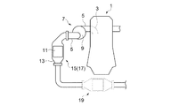
図1は、本発明の一実施形態に係る内燃機関の排ガス浄化触媒を備えた排ガス浄化システムの概略構成図である。
図1に示すように、内燃機関(例えばガソリンエンジン)1の燃焼室(不図示)と連通する排気ポート3が気筒毎に形成されている。そして、エンジン1には夫々の排気ポート3と連通するように排気管(排気通路)5が接続されている。
排気管5の排ガス流れ方向下流には、排気過給機7が設けられている。排気過給機7ではタービンハウジング9と排気管5とが連通し、エンジン1から排出される排ガスeのエネルギを利用して吸入された吸気を圧縮し、エンジン1の燃焼室に供給する。
排気管5には、排ガス浄化触媒11をケーシング13内に内蔵した触媒装置15が設けられている。
FIG. 1 is a schematic configuration diagram of an exhaust gas purification system including an exhaust gas purification catalyst for an internal combustion engine according to an embodiment of the present invention.
As shown in FIG. 1, an exhaust port 3 communicating with a combustion chamber (not shown) of an internal combustion engine (for example, a gasoline engine) 1 is formed for each cylinder. An exhaust pipe (exhaust passage) 5 is connected to the
An exhaust supercharger 7 is provided downstream of the
The
この触媒装置15は、排気過給機7の直下流側に設置された前段三元触媒17として設置される例を示し、前段三元触媒17だけによる排ガス浄化システムを示す。なお、後段側、例えば車両の床下に設けられる後段三元触媒19として設置されてよく、この場合には、前段三元触媒17と後段三元触媒19との両方の触媒を備える排気浄化システムであってもよい。
This
図2に示すように、排ガス浄化触媒11は、担持基材21と、担持基材21の表面に形成された触媒層23と、触媒層23に担持される触媒活性成分(不図示)で構成される。
As shown in FIG. 2, the exhaust
図2に示した実施形態では、担持基材21はハニカム構造体を形成し、例えばコーディエライト製や金属箔製のハニカム構造体で構成される。担持基材21は1個の担持基材(例えばハニカム構造体)で構成される。また、触媒層23は、排ガスの流れに接する第1の触媒層27と、第1の触媒層27の担持基材21側表面に形成され、担持基材21の表面に近い第2の触媒層25とから構成されている。
In the embodiment shown in FIG. 2, the supporting
第2の触媒層25の上流端部側の第2の触媒上流層25aには、触媒活性成分としてPd及びOSC材を含み、第1の触媒層27の上流端部側の第1の触媒上流層27aには、触媒成分としてRhを含んで構成されている。
また、第2の触媒層25の下流端部側の第2の触媒下流層25bには、触媒成分としてRhを含み、第1の触媒層27の下流端部側の第1の触媒下流層27bには、触媒成分としてPd及びOSC材を含んで構成されている。
また、第1の触媒下流層27bのOSC材の含有密度は、第2の触媒上流層25aのOSC材の含有密度より高く設定されている。
なお、第2の触媒上流層25a、及び第1の触媒下流層27bに担持された触媒成分のPdの一部、もしくは全部をPtにかえてもよい。
The second catalyst
The second catalyst
The density of the OSC material in the first catalyst
A part or all of Pd of the catalyst component supported on the second catalyst
担持基材21と、第1の触媒層27と、第2の触媒層25との積層状態の断面図を図3に示す。図3(A)は、担持基材21の上流端部側における積層状態であり、図3(B)は、担持基材21の下流端部側における積層状態をそれぞれ示す。
FIG. 3 shows a cross-sectional view of the stacked state of the
また、第1の触媒層27及び第2の触媒層25には、触媒成分として、例えば、担持基材21の容積1リットル当たり0.1〜3.0gのRhを含み、担持基材21の容積1リットル当たり1〜15gのPdもしくはPtを含む。さらに、OSC材は、例えば、CeO2やCeO2−ZrO2を主成分とする複合酸化物などで構成され、担持基材21の容積1リットル当たり1〜100gのOSC材をさらに含む。なお、第1の触媒層27と第2の触媒層25は、主成分としてアルミナ(Al2O3)、ジルコニア(ZrO2)、チタニア(TiO2)、セリア(CeO2)のうち少なくとも1つを含んで構成される酸化物母材に触媒主成分である貴金属を担持し、OSC材が添加されている。
The
このような実施形態によれば、第2の触媒上流層25aに担持される触媒成分は、Pd及びOSC材を含み、第1の触媒下流層27bに担持される触媒成分も同様に、Pd及びOSC材を含み、第1の触媒下流層27bに担持されるOSC材の含有密度は、第2の触媒上流層25aに担持されるOSC材の含有密度より高く設定することで、リン被毒を抑制し、排ガス浄化性能を向上することができる。
According to such an embodiment, the catalyst component supported by the second catalyst
リンは、触媒上流側から下流側へ、且つ上層から下層へ徐々に堆積する(図4、図5)。図4に示すよう触媒層23の表面から内部へと徐々に堆積する。また、図5に示すように、排ガス浄化触媒11の上流側から下流側へと徐々に堆積する。図5に示される複数のグラフの各線は、耐久試験条件(例えば、エンジンオイル中のリン濃度)の違いによるリンの堆積変化を示す。
従って、触媒層において下層側で下流側がリン被毒を最も受け難い位置であるといえる。しかし、下層側にOSC材を配置した場合には排ガスに晒されにくいため、酸素吸蔵機能が発揮されにくい。
Phosphorus is gradually deposited from the upstream side of the catalyst to the downstream side and from the upper layer to the lower layer (FIGS. 4 and 5). As shown in FIG. 4, the
Therefore, it can be said that the downstream side of the catalyst layer is the position where the downstream side is least susceptible to phosphorus poisoning. However, when the OSC material is arranged on the lower layer side, it is difficult to be exposed to the exhaust gas, so that the oxygen storage function is hardly exhibited.
そこで、リンによる被毒の影響を受けやすいOSC材とPdとを含む触媒層を、第2の触媒上流層25aと第1の触媒下流層27bにそれぞれ担持し、さらに、第1の触媒下流層27bに担持されるOSC材の担持密度を、第2の触媒上流層25aに担持されるOSC材の担持密度より高く設定することで、とリン被毒を抑制し、排ガス浄化性能の向上を可能にしている。
Therefore, a catalyst layer containing an OSC material and Pd that are easily affected by phosphorus poisoning is supported on the second catalyst
幾つかの実施形態では、図2において、第2の触媒上流層25aに担持されるPdの担持密度が、第1の触媒下流層27bに担持されるPdの担持密度より高くなるように設定されている。
すなわち、OSC材が高含有密度となる第1の触媒下流層27bでは、Pdを低担持密度とし、OSC材が低含有密度となる第2の触媒上流層25aでは、Pdを高担持密度に設定している。
In some embodiments, in FIG. 2, the support density of Pd supported on the second catalyst
That is, in the first catalyst
このような実施形態によれば、第2の触媒上流層25aのPd担持密度は、第1の触媒下流層27bのPd担持密度より高いことによって、低温時の排ガス浄化性能の向上が図れる。また、リン被毒の影響が比較的小さい下流側の上層に、低担持密度のPdと高含有密度のOSC材を配置することによって、高負荷運転における高排ガス流量時の排ガス浄化性能(とくに、NOx低減性能)を向上することができる。
According to such an embodiment, the Pd carrying density of the second catalyst
幾つかの実施形態では、図2において、第2の触媒層25の第2の触媒下流層25b、及び第1の触媒層27の第1の触媒上流層27aには、それぞれ触媒成分として、Rhを含むように構成されている。
このような実施形態によれば、第1の触媒上流層27a及び第2の触媒下流層25bに、NOx浄化活性に優れるRhを担持させることで、高負荷時の排ガス浄化性能(とくに、NOx低減性能)を確保することができる。
In some embodiments, the second catalyst
According to such an embodiment, the first catalyst
幾つかの実施形態では、図2において、第2の触媒下流層25b中のRhと、第1の触媒上流層27a中のRhは、同一担持密度に設定されている。これによって、同一Rhスラリーを利用できるので製造工程の簡素化及び材料コストの低減が図れる。
In some embodiments, in FIG. 2, Rh in the second catalyst
幾つかの実施形態では、図2において、Rhが担持された第2の触媒下流層25bと、同じ密度のRhが担持された第1の触媒上流層27aとが、連続して形成される連続部31を有して構成されている。
この連続部31は、図2に示すように、担持基材21の中心部に形成される。従って、図2のように第2の触媒上流層25aが担持基材21の1/2の長さに設けられ、そこに連続部31が形成されるように位置されても、図示されないが、連続部31の下流側に第1の触媒下流層27bが担持基材21の1/2の長さに設けられても、連続部31の中心が担持基材21の中心に位置するように形成されてもよい。
In some embodiments, in FIG. 2, the second catalyst
As shown in FIG. 2, the
この構成によって、同担持密度のRhを含む第2の触媒下流層25b及び第1の触媒上流層27aを、1回のスラリーコート工程で製造可能になるため、製造工程の簡素化及び材料コストの低減が図れる。図2の場合、スラリーコート順序は、1)25a、2)25aと25b、3)27bである。
With this configuration, the second catalyst
幾つかの実施形態では、図2において、Pd及びOSCを含む第2の触媒上流層25aと第1の触媒下流層27bの長さの和は、基材21の長さを超えないように構成されている。
すなわち、基材21の長さ内に第2の触媒上流層25aと、第1の触媒下流層27bとが、オーバーラップすることなく、基材21の上流端側と下流端側に配置されている。
これによって、第2の触媒上流層25aに担持された高担持密度のPdと低含有密度のOSC材、及び第1の触媒下流層27bに担持される低担持密度のPdと高含有密度のOSC材により、リン被毒を抑制し、排ガス浄化性能を高めることができる。
In some embodiments, in FIG. 2, the sum of the lengths of the second catalyst
That is, the second catalyst
As a result, the high support density Pd and the low content density OSC material supported on the second catalyst
第2の触媒上流層25aに担持された高担持密度のPdと低含有密度のOSC材、及び第1の触媒下流層27bに担持される低担持密度のPdと高含有密度のOSC材による作用効果をまとめると次のようになる。
1)第2の触媒上流層25aの高担持密度Pd:上流側であるため冷態時の排ガス浄化性能向上、及び下層のためリン堆積が進行した場合のPd触媒反応性向上。
2)第2の触媒上流層25aの低含有密度のOSC材:第1の触媒下流層27bのOSC材の高含有密度化が可能(OSC材総量一定の場合)。
3)第1の触媒下流層27bの低担持密度Pd:第2の触媒上流層25aのPdの高担持密度化が可能(Pd総量一定の場合)。
4)第1の触媒下流層27bに高含有密度OSC材:上層であるため排ガスとの接触性が高く、下流側であるためリン堆積が少ないので、リン堆積が進行した場合の排ガス浄化性能(とくに、NOx浄化性能)向上できる。
Actions by the high loading density Pd and low density OSC material carried on the second catalyst
1) High loading density Pd of the second catalyst
2) Low content density OSC material of the second catalyst
3) Low loading density Pd of the first catalyst
4) High content density OSC material in the first catalyst
幾つかの実施形態では、第2の触媒上流層25aに担持された高担持密度のPdと低含有密度のOSC材、第1の触媒下流層27bに担持される低担持密度のPdと高含有密度のOSC材を含み、第2の触媒下流層25bと第1の触媒上流層27aとには、それぞれ触媒成分として、Rhを含むように構成されている。
これら第2の触媒上流層25a、第2の触媒下流層25b、第1の触媒上流層27a、第1の触媒下流層27bの担持量のより好ましい設定例を次に示す。
第1の触媒上流層27a:Rh 0.1−2.0g/L
第1の触媒下流層27b:Pd 1.0−5.0g/L、OSC材 20−60g/L
第2の触媒上流層25a:Pd 3.0−10g/L、OSC材 5−40g/L
第2の触媒下流層25b:Rh 0.1−2.0g/L
上記設定例の数値を採用することで、リン被毒を抑制し、排ガス浄化性能を高めることができる。
In some embodiments, high loading density Pd and low density OSC material supported on the second catalyst
A more preferable setting example of the loading amounts of the second catalyst
First catalyst
First catalyst
Second catalyst
Second catalyst
By adopting the numerical values in the above setting examples, phosphorus poisoning can be suppressed and exhaust gas purification performance can be improved.
幾つかの実施形態では、図2において、第2の触媒上流層25aは、担持基材21の1/2の長さを有して構成されている。
これによって、第2の触媒上流層25aに担持されたPdの高密度化と低含有密度のOSC材による効果を確実に得ることができる。
なお、図2では、第2の触媒上流層25aの長さが担持基材21の長さの1/2の場合を示しているが、第2の触媒上流層25aは担持基材21の長さの30%〜70%の範囲に設定できる。第2の触媒上流層25aの長さを短く設定して、Pdの担持密度を高めると、低温時の排ガス浄化性能が高まる効果を得ることができる。なお、第2の触媒上流層25aの長さを30%より小さく設定すると、触媒層内のガス反応時間が短くなるため、Pd担持密度増大の効果を十分引き出せず、返って排ガス浄化性能が低下する。また、第2の触媒上流層25aの長さを70%より大きく設定すると、設定できるPd担持密度が低くなり、低温時の排ガス上性能が悪化する。したがって、より好ましい第2の触媒上流層25aの長さは、基材の長さの30%〜50%である。
In some embodiments, in FIG. 2, the second catalyst
As a result, it is possible to reliably obtain the effect of increasing the density of Pd supported on the second catalyst
FIG. 2 shows the case where the length of the second catalyst
幾つかの実施形態では、図6の実施例2に示すように、Pd及びOSC材を含む第2の触媒上流層35aと第1の触媒下流層37bは、担持基材21の上流端側と下流端側に同一長さに均等に配置されている。
なお、図2の実施形態であっても、連続部31の中心を担持基材21の中心に位置するように配置することで、第2の触媒上流層25aと第1の触媒下流層27bとを同一長さとすることができる。
In some embodiments, as shown in Example 2 of FIG. 6, the second catalyst
In the embodiment of FIG. 2 as well, the second catalyst
このような実施形態によれば、第2の触媒上流層35aと第1の触媒下流層37bとが、担持基材21の上流端側と下流端側に形成されることで、第2の触媒上流層35aに担持されたPdの高密度化と低担持密度のOSC材による冷態時の排ガス浄化性能の向上とリン被毒の抑制効果と、第1の触媒下流層37bに担持された低担持密度のPdと高担持密度のOSC材による高負荷時の排ガス浄化性能(とくに、NOx低減性能)の向上とリン被毒の抑制効果と、を共に得ることができる。
なお、図6の実施例2では、触媒層35aの長さが基材の長さの1/2の場合を示しているが、触媒層35aは基材の長さの30%〜50%の範囲に設定できる。触媒層35aの長さを短く設定して、Pdの担持密度を高めると、低温時の排ガス浄化性能が高まる効果を得ることができる。
According to such an embodiment, the second catalyst
In addition, although Example 2 of FIG. 6 shows the case where the length of the
次に、排ガス浄化触媒11をさらに説明するために図6に実施例を示す。
Pd(OSC材含む)、及びRhの総貴金属担持重量を同じに設定して、所定の試験運転パターンによって、冷態始動後の一定時間、及び高負荷運転時のそれぞれについて、排ガス中のNOx、CO、HCの排出量を評価した。
Next, in order to further explain the exhaust
The total precious metal loading weight of Pd (including OSC material) and Rh is set to be the same, and according to a predetermined test operation pattern, NOx in the exhaust gas for each of a fixed time after cold start and high load operation, CO and HC emissions were evaluated.
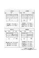
比較例1は、第2の触媒層125のPd(OSC材含む)、及び第1の触媒層127のRhを、それぞれの触媒層に担持基材21の全長に亘って均一に担持した場合である。
比較例2は、第2の触媒層135のPd(OSC材含む)を担持基材21の長さの1/2で第2の触媒上流層135aと第2の触媒下流層135bに2分割した場合である。
Comparative Example 1 is a case where Pd (including the OSC material) of the
In Comparative Example 2, Pd (including the OSC material) of the second catalyst layer 135 was divided into two parts, that is, a second catalyst
実施例1は、図2に示した実施形態であり、第2の触媒上流層25aを上流端から担持基材21の長さの1/2までとし、連続部31を介して、下流側に第1の触媒下流層27bが設けられる。この第1の触媒下流層27bの長さは、連続部31の厚さがあるが、担持基材21の略1/2に形成され、第2の触媒上流層25aの長さと略同じ長さを有している。
Example 1 is the embodiment shown in FIG. 2, and the second catalyst
実施例2は、第2の触媒上流層35aと第1の触媒上流層37aとは同一長さで、担持基材21の長さの1/2を有し、第2の触媒下流層35bと第1の触媒下流層37bとは同一長さで、担持基材21の長さの1/2を有している。
そして、比較例1、比較例2、実施例1、実施例2の夫々におけるPd、Rhの担持密度は、図7に示した夫々の模式図の下部に、分割領域毎に(ゾーン毎に)記載した。
In the second embodiment, the second catalyst
And the carrying density of Pd and Rh in each of Comparative Example 1, Comparative Example 2, Example 1, and Example 2 is for each divided region (for each zone) at the bottom of each schematic diagram shown in FIG. Described.
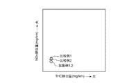
排ガス浄化性能試験の結果を図7、8に示す。
図7は、比較例1、2と実施例1、2とのエンジンの冷態始動時における、HC、NOx排出量の比較を示す。また、図8は、比較例1、2と実施例1、2とのエンジン高負荷時における、HC、NOx排出量の比較を示す。実施例1、2は実質同一の排ガス量を示す結果である。
これら図7、8から、実施例1、2が、比較例1に比べて、冷態始動後の排ガス浄化性能の向上効果と、高負荷運転の高い排ガス浄化性能を保持していることを確認できた。
The results of the exhaust gas purification performance test are shown in FIGS.
FIG. 7 shows a comparison of HC and NOx emission amounts at the time of cold start of the engine of Comparative Examples 1 and 2 and Examples 1 and 2. FIG. 8 shows a comparison of HC and NOx emission amounts between Comparative Examples 1 and 2 and Examples 1 and 2 at a high engine load. Examples 1 and 2 are results showing substantially the same amount of exhaust gas.
From these FIGS. 7 and 8, it is confirmed that Examples 1 and 2 retain the improvement effect of exhaust gas purification performance after cold start and the high exhaust gas purification performance of high load operation as compared with Comparative Example 1. did it.
Pd(OSC材を含む)が担持される触媒層を、Rhが担持される触媒層に対して、上流部は下に、下流部は上に配置することによって、すなわち、第2の触媒上流層25a、及び第1の触媒下流層27bにそれぞれ配置することによって、エンジンオイル由来成分であるリンの被毒による性能の低下を抑制して、冷態時のエンジン始動から高負荷運転に排出する有害ガスを効果的に浄化することが確認できた。
By disposing the catalyst layer on which Pd (including the OSC material) is supported with respect to the catalyst layer on which Rh is supported, the upstream portion is located below and the downstream portion is located above, that is, the second catalyst upstream layer. 25a and the first catalyst
本発明の少なくとも一実施形態によれば、エンジンオイル由来成分であるリンによる被毒の影響が抑制し、エンジンの始動後から高負荷時に排出するNOxを効果的に浄化することができるので、内燃機間の排ガス浄化装置への利用に適している。 According to at least one embodiment of the present invention, the influence of poisoning caused by phosphorus, which is an engine oil-derived component, is suppressed, and NOx discharged at high load after engine startup can be effectively purified. Suitable for use in exhaust gas purification equipment.
1 エンジン(内燃機関)
5 排気管(排ガス通路)
21 担持基材(基材)
23 触媒層
11 排ガス浄化触媒
15 触媒装置
25、35 第2の触媒層
27、37 第1の触媒層
25a、35a 第2の触媒上流層
27a、37a 第1の触媒上流層
25b、35b 第2の触媒下流層
27b、37b 第1の触媒下流層
Pd、Rh、OSC 触媒成分
1 engine (internal combustion engine)
5 Exhaust pipe (exhaust gas passage)
21 Support base material (base material)
23
Claims (7)
前記触媒層は、排ガス流れに接する第1の触媒層と、
前記第1の触媒層の基材側表面に形成される第2の触媒層と、から形成され、
前記第2の触媒層の前記排ガス流れに対し上流側を構成する第2の触媒上流層に担持される触媒成分は、パラジウム(Pd)と白金(Pt)の少なくとも一方及び酸素吸蔵材を含み、
前記第1の触媒層の前記排ガス流れに対し下流側を構成する第1の触媒下流層に担持される触媒成分は、PdまたはPtの少なく一方及び酸素吸蔵材を含み、
前記第1の触媒下流層に含有される前記酸素吸蔵材量は、前記第2の触媒上流層に含有される前記酸素吸蔵材量より多いことを特徴とする内燃機関の排ガス浄化触媒。 In an exhaust gas purification catalyst for an internal combustion engine that is disposed in an exhaust gas passage of an engine and includes a base material, a catalyst layer formed on the surface of the base material, and a catalyst component supported on the catalyst layer,
The catalyst layer includes a first catalyst layer in contact with the exhaust gas flow;
A second catalyst layer formed on the substrate side surface of the first catalyst layer,
The catalyst component supported on the second catalyst upstream layer constituting the upstream side of the exhaust gas flow of the second catalyst layer includes at least one of palladium (Pd) and platinum (Pt) and an oxygen storage material,
The catalyst component supported on the first catalyst downstream layer constituting the downstream side of the exhaust gas flow of the first catalyst layer includes at least one of Pd or Pt and an oxygen storage material,
An exhaust gas purification catalyst for an internal combustion engine, wherein the amount of the oxygen storage material contained in the first catalyst downstream layer is greater than the amount of the oxygen storage material contained in the second catalyst upstream layer.
Priority Applications (3)
| Application Number | Priority Date | Filing Date | Title |
|---|---|---|---|
| JP2016092555A JP2017200676A (en) | 2016-05-02 | 2016-05-02 | Exhaust gas purification catalyst of internal combustion engine |
| EP17163077.5A EP3241613A1 (en) | 2016-05-02 | 2017-03-27 | Exhaust gas purification catalyst for internal combustion engine |
| US15/471,113 US10213741B2 (en) | 2016-05-02 | 2017-03-28 | Exhaust gas purification catalyst for internal combustion engine |
Applications Claiming Priority (1)
| Application Number | Priority Date | Filing Date | Title |
|---|---|---|---|
| JP2016092555A JP2017200676A (en) | 2016-05-02 | 2016-05-02 | Exhaust gas purification catalyst of internal combustion engine |
Publications (1)
| Publication Number | Publication Date |
|---|---|
| JP2017200676A true JP2017200676A (en) | 2017-11-09 |
Family
ID=58448399
Family Applications (1)
| Application Number | Title | Priority Date | Filing Date |
|---|---|---|---|
| JP2016092555A Pending JP2017200676A (en) | 2016-05-02 | 2016-05-02 | Exhaust gas purification catalyst of internal combustion engine |
Country Status (3)
| Country | Link |
|---|---|
| US (1) | US10213741B2 (en) |
| EP (1) | EP3241613A1 (en) |
| JP (1) | JP2017200676A (en) |
Cited By (13)
| Publication number | Priority date | Publication date | Assignee | Title |
|---|---|---|---|---|
| JP2019072203A (en) * | 2017-10-16 | 2019-05-16 | 株式会社三洋物産 | Game machine |
| JP2019072205A (en) * | 2017-10-16 | 2019-05-16 | 株式会社三洋物産 | Game machine |
| JP2019072207A (en) * | 2017-10-16 | 2019-05-16 | 株式会社三洋物産 | Game machine |
| JP2019072210A (en) * | 2017-10-16 | 2019-05-16 | 株式会社三洋物産 | Game machine |
| JP2019072212A (en) * | 2017-10-16 | 2019-05-16 | 株式会社三洋物産 | Game machine |
| JP2019072211A (en) * | 2017-10-16 | 2019-05-16 | 株式会社三洋物産 | Game machine |
| JP2019072206A (en) * | 2017-10-16 | 2019-05-16 | 株式会社三洋物産 | Game machine |
| JP2019072204A (en) * | 2017-10-16 | 2019-05-16 | 株式会社三洋物産 | Game machine |
| JP2019072208A (en) * | 2017-10-16 | 2019-05-16 | 株式会社三洋物産 | Game machine |
| WO2019131796A1 (en) * | 2017-12-28 | 2019-07-04 | ユミコア日本触媒株式会社 | Phosphorus-compound-containing-exhaust-gas purifying catalyst |
| JP2021055628A (en) * | 2019-09-30 | 2021-04-08 | 株式会社Subaru | Exhaust gas purification apparatus |
| JP2021154191A (en) * | 2020-03-25 | 2021-10-07 | トヨタ自動車株式会社 | Exhaust gas purifying catalyst |
| WO2025203201A1 (en) * | 2024-03-25 | 2025-10-02 | 株式会社キャタラー | Exhaust gas purification catalyst |
Families Citing this family (12)
| Publication number | Priority date | Publication date | Assignee | Title |
|---|---|---|---|---|
| US10960389B2 (en) * | 2016-05-24 | 2021-03-30 | Cataler Corporation | Exhaust gas purification catalyst |
| JP6693406B2 (en) * | 2016-12-20 | 2020-05-13 | 三菱自動車工業株式会社 | Exhaust gas purification device |
| GB2560941A (en) * | 2017-03-29 | 2018-10-03 | Johnson Matthey Plc | NOx Adsorber catalyst |
| GB2560940A (en) * | 2017-03-29 | 2018-10-03 | Johnson Matthey Plc | Three layer NOx Adsorber catalyst |
| GB2560942A (en) * | 2017-03-29 | 2018-10-03 | Johnson Matthey Plc | NOx Adsorber catalyst |
| JP6408062B1 (en) * | 2017-04-28 | 2018-10-17 | 株式会社キャタラー | Exhaust gas purification catalyst |
| JP6735912B2 (en) * | 2017-04-28 | 2020-08-05 | ユミコア日本触媒株式会社 | Exhaust gas purification catalyst and exhaust gas purification method using the same |
| US11161098B2 (en) * | 2018-05-18 | 2021-11-02 | Umicore Ag & Co. Kg | Three-way catalyst |
| JP6778845B1 (en) * | 2019-01-22 | 2020-11-04 | 三井金属鉱業株式会社 | Exhaust gas purification catalyst |
| JP6775052B2 (en) * | 2019-03-27 | 2020-10-28 | 株式会社キャタラー | Exhaust gas purification catalyst |
| US12465908B2 (en) * | 2019-12-18 | 2025-11-11 | Mitsui Mining & Smelting Co., Ltd. | Exhaust gas purification catalyst |
| JP7061655B1 (en) * | 2020-11-06 | 2022-04-28 | 株式会社キャタラー | Exhaust gas purification catalyst device |
Citations (1)
| Publication number | Priority date | Publication date | Assignee | Title |
|---|---|---|---|---|
| WO2015087871A1 (en) * | 2013-12-13 | 2015-06-18 | 株式会社キャタラー | Exhaust gas purification catalyst |
Family Cites Families (4)
| Publication number | Priority date | Publication date | Assignee | Title |
|---|---|---|---|---|
| US7678347B2 (en) * | 2005-07-15 | 2010-03-16 | Basf Catalysts Llc | High phosphorous poisoning resistant catalysts for treating automobile exhaust |
| US7622096B2 (en) * | 2007-08-09 | 2009-11-24 | Basf Catalysts Llc | Multilayered catalyst compositions |
| JP5287884B2 (en) | 2011-01-27 | 2013-09-11 | トヨタ自動車株式会社 | Exhaust gas purification catalyst |
| JP6102608B2 (en) | 2013-07-26 | 2017-03-29 | マツダ株式会社 | Exhaust gas purification catalyst |
-
2016
- 2016-05-02 JP JP2016092555A patent/JP2017200676A/en active Pending
-
2017
- 2017-03-27 EP EP17163077.5A patent/EP3241613A1/en not_active Withdrawn
- 2017-03-28 US US15/471,113 patent/US10213741B2/en not_active Expired - Fee Related
Patent Citations (1)
| Publication number | Priority date | Publication date | Assignee | Title |
|---|---|---|---|---|
| WO2015087871A1 (en) * | 2013-12-13 | 2015-06-18 | 株式会社キャタラー | Exhaust gas purification catalyst |
Cited By (17)
| Publication number | Priority date | Publication date | Assignee | Title |
|---|---|---|---|---|
| JP2019072208A (en) * | 2017-10-16 | 2019-05-16 | 株式会社三洋物産 | Game machine |
| JP2019072203A (en) * | 2017-10-16 | 2019-05-16 | 株式会社三洋物産 | Game machine |
| JP2019072207A (en) * | 2017-10-16 | 2019-05-16 | 株式会社三洋物産 | Game machine |
| JP2019072210A (en) * | 2017-10-16 | 2019-05-16 | 株式会社三洋物産 | Game machine |
| JP2019072212A (en) * | 2017-10-16 | 2019-05-16 | 株式会社三洋物産 | Game machine |
| JP2019072211A (en) * | 2017-10-16 | 2019-05-16 | 株式会社三洋物産 | Game machine |
| JP2019072206A (en) * | 2017-10-16 | 2019-05-16 | 株式会社三洋物産 | Game machine |
| JP2019072204A (en) * | 2017-10-16 | 2019-05-16 | 株式会社三洋物産 | Game machine |
| JP2019072205A (en) * | 2017-10-16 | 2019-05-16 | 株式会社三洋物産 | Game machine |
| WO2019131796A1 (en) * | 2017-12-28 | 2019-07-04 | ユミコア日本触媒株式会社 | Phosphorus-compound-containing-exhaust-gas purifying catalyst |
| JP6544881B1 (en) * | 2017-12-28 | 2019-07-17 | ユミコア日本触媒株式会社 | Phosphorus compound-containing catalyst for exhaust gas purification |
| US11110436B2 (en) | 2017-12-28 | 2021-09-07 | Umicore Shokubai Japan Co., Ltd. | Phosphorus compound-containing exhaust gas purifying catalyst |
| JP2021055628A (en) * | 2019-09-30 | 2021-04-08 | 株式会社Subaru | Exhaust gas purification apparatus |
| JP7393176B2 (en) | 2019-09-30 | 2023-12-06 | 株式会社Subaru | Exhaust gas purification device |
| JP2021154191A (en) * | 2020-03-25 | 2021-10-07 | トヨタ自動車株式会社 | Exhaust gas purifying catalyst |
| JP7248616B2 (en) | 2020-03-25 | 2023-03-29 | トヨタ自動車株式会社 | Exhaust gas purification catalyst |
| WO2025203201A1 (en) * | 2024-03-25 | 2025-10-02 | 株式会社キャタラー | Exhaust gas purification catalyst |
Also Published As
| Publication number | Publication date |
|---|---|
| US10213741B2 (en) | 2019-02-26 |
| US20170312690A1 (en) | 2017-11-02 |
| EP3241613A1 (en) | 2017-11-08 |
Similar Documents
| Publication | Publication Date | Title |
|---|---|---|
| JP2017200676A (en) | Exhaust gas purification catalyst of internal combustion engine | |
| JP6724531B2 (en) | Exhaust gas purification catalyst for internal combustion engine | |
| US10071342B2 (en) | Three-way catalytic converter | |
| JP6445228B1 (en) | Exhaust gas purification catalyst | |
| JP6724532B2 (en) | Exhaust gas purification catalyst manufacturing method and exhaust gas purification catalyst | |
| JP6539666B2 (en) | Exhaust gas purification catalyst | |
| US9616410B2 (en) | Exhaust gas purifying catalyst | |
| EP1952884A1 (en) | Catalyst for exhaust-gas purification | |
| CN118564325A (en) | Catalytic article and use thereof for treating exhaust gases | |
| EP2875862B1 (en) | Catalyst for cleaning exhaust gas | |
| CN107249736A (en) | Catalyst for Exhaust Purification | |
| WO2022097498A1 (en) | Exhaust gas purification catalyst device | |
| EP2184459A1 (en) | Exhaust gas purification device | |
| WO2015111555A1 (en) | Exhaust-gas purifying catalyst for lean-burn engine | |
| JPWO2011118047A1 (en) | Exhaust gas purification catalyst | |
| JP5987519B2 (en) | Exhaust gas purification catalyst structure | |
| JP2021079313A (en) | Catalyst for cleaning exhaust gas | |
| JP2010058069A (en) | Catalyst for purification of exhaust gas for motorcycles | |
| CN102650227B (en) | Exhaust emission control device for internal combustion engine | |
| JP7215487B2 (en) | Exhaust gas purification catalyst | |
| JP2021126636A (en) | Exhaust emission control catalyst device | |
| JP5558013B2 (en) | Exhaust purification catalyst and exhaust treatment apparatus using the same | |
| JP2023135093A (en) | Method for manufacturing exhaust gas purification catalyst | |
| JP2006231108A (en) | Exhaust gas purification device | |
| JP2023060392A (en) | Exhaust gas purifying apparatus |
Legal Events
| Date | Code | Title | Description |
|---|---|---|---|
| A621 | Written request for application examination |
Free format text: JAPANESE INTERMEDIATE CODE: A621 Effective date: 20190322 |
|
| A977 | Report on retrieval |
Free format text: JAPANESE INTERMEDIATE CODE: A971007 Effective date: 20191121 |
|
| A131 | Notification of reasons for refusal |
Free format text: JAPANESE INTERMEDIATE CODE: A131 Effective date: 20191126 |
|
| A601 | Written request for extension of time |
Free format text: JAPANESE INTERMEDIATE CODE: A601 Effective date: 20200120 |
|
| A521 | Request for written amendment filed |
Free format text: JAPANESE INTERMEDIATE CODE: A523 Effective date: 20200323 |
|
| A131 | Notification of reasons for refusal |
Free format text: JAPANESE INTERMEDIATE CODE: A131 Effective date: 20200526 |
|
| A521 | Request for written amendment filed |
Free format text: JAPANESE INTERMEDIATE CODE: A523 Effective date: 20200727 |
|
| A131 | Notification of reasons for refusal |
Free format text: JAPANESE INTERMEDIATE CODE: A131 Effective date: 20201124 |
|
| A02 | Decision of refusal |
Free format text: JAPANESE INTERMEDIATE CODE: A02 Effective date: 20210803 |