JP2017200711A - Drilling device - Google Patents
Drilling device Download PDFInfo
- Publication number
- JP2017200711A JP2017200711A JP2016092607A JP2016092607A JP2017200711A JP 2017200711 A JP2017200711 A JP 2017200711A JP 2016092607 A JP2016092607 A JP 2016092607A JP 2016092607 A JP2016092607 A JP 2016092607A JP 2017200711 A JP2017200711 A JP 2017200711A
- Authority
- JP
- Japan
- Prior art keywords
- unit
- drilling
- moving
- adjustment mechanism
- workpiece
- Prior art date
- Legal status (The legal status is an assumption and is not a legal conclusion. Google has not performed a legal analysis and makes no representation as to the accuracy of the status listed.)
- Granted
Links
Images


Landscapes
- Perforating, Stamping-Out Or Severing By Means Other Than Cutting (AREA)
Abstract
【課題】穿孔位置のずれを抑制しつつ位置合わせできる穿孔装置を提供する。【解決手段】ワークに穿孔を行う第1穿孔ユニットと、X方向及びX方向と交差するY方向のそれぞれに移動可能な移動部35と、移動部35を移動可能に支持する支持部36と、移動部35に固定されて移動部35と共に移動可能であってワークに穿孔を行う第2穿孔ユニットと、X方向及びY方向の双方と交差する高さ方向Zに沿って直線運動して移動部35及び支持部36の一方を他方に押し付けることで移動部35の移動を制限する制動機構40とを備える。【選択図】図3A punching device capable of performing alignment while suppressing displacement of the punching position is provided. A first punching unit that punches a workpiece, a moving part that can move in an X direction and a Y direction that intersects the X direction, a support part that movably supports the moving part, A second drilling unit fixed to the moving part 35 and movable together with the moving part 35 for drilling holes in the workpiece; and a braking mechanism 40 that restricts the movement of the moving part 35 by pressing one of the 35 and the supporting part 36 against the other. [Selection drawing] Fig. 3
Description
本発明は、例えばセラミックグリーンシートなどのワークに穿孔する穿孔装置に関する。 The present invention relates to a punching device for punching a workpiece such as a ceramic green sheet.
従来から、X方向(第1方向)に並列状に配置された複数の穿孔ユニットと、各穿孔ユニットが穿孔する穿孔位置の間隔をX方向に微調整するためのX軸操作盤と、Y方向(第2方向)に微調整するためのY軸操作部材とを備えた穿孔装置が知られている(特許文献1)。 Conventionally, a plurality of drilling units arranged in parallel in the X direction (first direction), an X-axis operation panel for finely adjusting the interval between the drilling positions where each drilling unit drills in the X direction, and the Y direction A perforating apparatus including a Y-axis operating member for fine adjustment in the (second direction) is known (Patent Document 1).
ところで、穿孔ユニットは、ユニットベース(支持部)上に配置されてX方向とY方向に微調整された後、ボルトとナットによりユニットベースに固定されていた。そのため、ボルトの締め付け方向(第3方向)に作用する押圧力が十分に大きくなる前に、ボルトの回動に伴ってX方向やY方向にも力が作用する。その結果、穿孔ユニットの姿勢が変化し、穿孔位置がずれてしまうことがあった。 By the way, the drilling unit is arranged on the unit base (supporting portion) and finely adjusted in the X direction and the Y direction, and then fixed to the unit base with bolts and nuts. Therefore, before the pressing force acting in the bolt tightening direction (third direction) becomes sufficiently large, force acts in the X direction and the Y direction as the bolt rotates. As a result, the posture of the drilling unit may change, and the drilling position may shift.
本発明は、こうした実情に鑑みてなされたものであり、その目的は、穿孔位置のずれを抑制しつつ位置合わせできる穿孔装置を提供することにある。 The present invention has been made in view of such circumstances, and an object of the present invention is to provide a drilling device that can be positioned while suppressing a shift in the drilling position.
以下、上記課題を解決するための手段及びその作用効果について記載する。
上記課題を解決する穿孔装置は、ワークに穿孔を行う第1穿孔ユニットと、第1方向及び該第1方向と交差する第2方向のそれぞれに移動可能な移動部と、該移動部を移動可能に支持する支持部と、前記移動部に固定されて該移動部と共に移動可能であって前記ワークに穿孔を行う第2穿孔ユニットと、前記第1方向及び前記第2方向の双方と交差する第3方向に沿って直線運動して前記移動部及び前記支持部の一方を他方に押し付けることで前記移動部の移動を制限する制動機構とを備える。
Hereinafter, means for solving the above-described problems and the effects thereof will be described.
A drilling device that solves the above problems includes a first drilling unit that drills a workpiece, a moving unit that is movable in each of a first direction and a second direction that intersects the first direction, and the movable unit is movable. A second support unit that is fixed to the moving unit, is movable with the moving unit, and performs drilling on the workpiece, and intersects both the first direction and the second direction. A braking mechanism that linearly moves along three directions and restricts the movement of the moving unit by pressing one of the moving unit and the supporting unit against the other.
この構成によれば、制動機構は、第3方向に沿って直線運動して移動部及び支持部の一方を他方に押し付けることにより、移動部が第1方向及び第2方向へ移動するのを抑制しつつ移動部の移動を制限できる。したがって、穿孔位置のずれを抑制しつつ位置合わせできる。 According to this configuration, the braking mechanism restrains the moving unit from moving in the first direction and the second direction by linearly moving along the third direction and pressing one of the moving unit and the support unit against the other. However, the movement of the moving unit can be restricted. Therefore, alignment can be performed while suppressing the deviation of the drilling position.
上記穿孔装置において、前記支持部において前記移動部を支持する支持面と、前記移動部において前記支持部に支持される被支持面と、のうち少なくとも一方の面には、空気が流動可能な空気流路が開口するのが好ましい。 In the perforating apparatus, air that allows air to flow is provided on at least one of a support surface that supports the moving portion in the support portion and a supported surface that is supported by the support portion in the moving portion. It is preferable that the flow path opens.
この構成によれば、空気流路に空気を送り込むと、支持面と被支持面とのうち少なくとも一方の面に形成された開口から空気が吹き出す。これにより、支持面と被支持面との間の摩擦力が低減され、移動部を容易に移動させることができる。 According to this configuration, when air is sent into the air flow path, air blows out from an opening formed in at least one of the support surface and the supported surface. Thereby, the frictional force between a support surface and a to-be-supported surface is reduced, and a moving part can be moved easily.
上記穿孔装置は、前記第1穿孔ユニットが前記ワークに穿孔する第1穿孔位置と前記第2穿孔ユニットが前記ワークに穿孔する第2穿孔位置とを検出する検出部と、前記移動部の前記第1方向における位置を調整する第1調整機構と、前記移動部の前記第2方向における位置を調整する第2調整機構と、前記検出部の検出結果に基づいて前記第1調整機構と前記第2調整機構とを制御する制御部とをさらに備えるのが好ましい。 The punching device includes a detection unit that detects a first drilling position at which the first drilling unit punches the workpiece and a second drilling position at which the second drilling unit punches the workpiece, and the first of the moving unit. A first adjusting mechanism for adjusting a position in one direction; a second adjusting mechanism for adjusting a position of the moving unit in the second direction; and the first adjusting mechanism and the second based on a detection result of the detecting unit. It is preferable to further include a control unit that controls the adjustment mechanism.
この構成によれば、検出部の検出結果に基づいて制御部が第1調整機構と第2調整機構を制御して移動部の位置を調整するため、第1穿孔位置に対する第2穿孔位置の位置合わせを自動で行うことができる。 According to this configuration, since the control unit controls the first adjustment mechanism and the second adjustment mechanism based on the detection result of the detection unit to adjust the position of the moving unit, the position of the second drilling position with respect to the first drilling position. Matching can be performed automatically.
本発明によれば、穿孔位置のずれを抑制しつつ位置合わせできる。 According to the present invention, alignment can be performed while suppressing the deviation of the drilling position.
以下、穿孔装置の一実施形態について図面を参照して説明する。
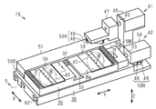
図1に示すように、穿孔装置11は、平面視で略矩形状の機台12と、ワークWを移動させる移動機構13と、ワークWに穿孔を行う複数(本実施形態では2つ)の穿孔ユニット14が着脱可能に取り付けられる基部15とを備えている。また、穿孔装置11は、位置決めの基準となる第1穿孔ユニット14aに対して第2穿孔ユニット14bの位置を調整する少なくとも1つ(本実施形態では1つ)の調整装置16を備えている。すなわち、調整装置16は、第2穿孔ユニット14bを移動させることにより、第1穿孔ユニット14a及び第2穿孔ユニット14bの間隔を調整する。なお、本実施形態の第1穿孔ユニット14aと第2穿孔ユニット14bの構成は同じである。さらに、基部15には、例えば穿孔されたワークWを撮像することにより、第1穿孔ユニット14aと第2穿孔ユニット14bの穿孔位置を検出するカメラなどの検出部17が取り付けられている。
Hereinafter, an embodiment of a perforating apparatus will be described with reference to the drawings.
As shown in FIG. 1, the
そして、以下の説明では、穿孔装置11及び穿孔装置11に取り付けられた状態の調整装置16において、複数の穿孔ユニット14の並び方向を第1方向の一例であるX方向とし、X方向と交差する方向を第2方向の一例であるY方向とする。さらに、X方向及びY方向の双方と交差する方向を第3方向の一例である高さ方向Zとする。なお、本実施形態の高さ方向Zは、鉛直方向に沿う方向であり、X方向、Y方向、及び高さ方向Zはそれぞれ直交している。
In the following description, in the
移動機構13は、Y方向に沿って設けられた第1ボールねじ18と、第1ボールねじ18の駆動に伴ってY方向に移動するテーブル部19と、X方向に沿ってテーブル部19に設けられた第2ボールねじ20とを備えている。そして、第2ボールねじ20には、ワークWを着脱可能に保持する保持部21が接続されている。すなわち、ワークW及び保持部21は、第1ボールねじ18の駆動に伴ってY方向に移動されると共に、第2ボールねじ20の駆動に伴ってX方向に移動される。
The
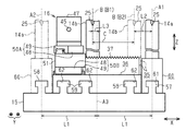
図2に示すように、穿孔ユニット14は、高さ方向Zの略中央部にY方向に沿って形成された切欠部23を有する本体部24と、ワークWを穿孔するパンチ25及びダイ26と、パンチ25を打動する打動機構27とを備えている。なお、本実施形態におけるパンチ25は、穿孔ユニット14のX方向における略中央位置に設けられている。
As shown in FIG. 2, the
さらに、本体部24の底面24aには、例えば頭部のない寸切ボルトなどのボルト28が挿通される挿通孔29が形成されていると共に、本体部24の側面には、ボルト28の一端(上端)側に螺合するナット30を外部に露出させる窓部31が形成されている。
In addition, an
また、調整装置16には、ボルト28の他端(下端)側に螺合する座付ナット32と係合する溝部33が形成されている。すなわち、第2穿孔ユニット14bは、ボルト28、ナット30、及び座付ナット32により調整装置16に固定されている。
Further, the adjusting
さらに、調整装置16は、溝部33が形成されてX方向及びY方向のそれぞれに移動可能な移動部35と、移動部35を移動可能に支持する支持部36とを備えている。なお、溝部33は、開口面積が底面積よりも小さい所謂T溝であり、X方向に沿って形成されている。
Further, the
図3に示すように、移動部35の上面35aにおけるY方向の両端部には、Y方向に沿って延びる複数の凸部及び凹部により第2穿孔ユニット14bをY方向に案内する案内部37が形成されている。さらに、Y方向における溝部33の両側の位置であって、溝部33と案内部37との間には、目盛38が付けられたプレート39がそれぞれ固定されている。そして、高さ方向Zにおいてプレート39と支持部36との間の位置には、高さ方向Zに直線運動して移動部35及び支持部36の一方を他方に押し付けることで移動部35の移動を制限する少なくとも1つ(本実施形態では2つ)の制動機構40が設けられている。
As shown in FIG. 3, guide
また、調整装置16は、移動部35のX方向における位置を調整する第1調整機構41と、移動部35のY方向における位置を調整する第2調整機構42とを備えている。なお、第1調整機構41と第2調整機構42は、X方向に位置をずらして隣り合うように設けられている。
The
第1調整機構41は、Y方向に沿って設けられた第1ねじ軸45を正回転もしくは逆回転させる例えばモーターなどの第1駆動源46と、第1ねじ軸45が回動するのに伴ってY方向に往復移動可能な第1可動部47とを備えている。
The
さらに、第1調整機構41は、第1可動部47に固定されたブロック48及びブロック48を案内する案内レール49を有する第1直動ガイド50Aと、X方向にスライド移動可能に設けられたスライド部51とを備えている。なお、第1直動ガイド50Aの案内レール49は、X方向及びY方向の双方に対して斜め(例えば45度)に設けられ、スライド部51に固定されている。そして、スライド部51と移動部35は、Y方向に沿って形成されたレール状の接続部(図示略)を介して接続されており、X方向に対しては一体的に移動し、Y方向に対しては個別に移動可能に設けられている。
Further, the
また、第2調整機構42は、Y方向に沿って設けられた第2ねじ軸53を正回転もしくは逆回転させる例えばモーターなどの第2駆動源54と、第2ねじ軸53が回動するのに伴ってY方向に往復移動可能な第2可動部55とを備えている。なお、第2可動部55は、移動部35に固定されている。また、スライド部51及び第2調整機構42は、案内レール49がX方向に沿うように設けられた少なくとも1つ(本実施形態では3つ)の第2直動ガイド50Bにそれぞれ支持されている。
In addition, the
図4に示すように、基部15は、第1穿孔ユニット14aを取り付け可能な第1基準取付部57及び第2基準取付部58を有している。さらに、基部15は、X方向において第1基準取付部57と第2基準取付部58の間に位置し、調整装置16が有する支持部36を取り付け可能な取付部59を有している。
As shown in FIG. 4, the
一方、第1穿孔ユニット14aが固定される台座60には、第1基準取付部57及び第2基準取付部58と係合可能な基準取付溝61が形成されていると共に、支持部36には、取付部59と係合可能な取付溝62が形成されている。なお、第1基準取付部57、第2基準取付部58、及び取付部59は、先端部のX方向における幅が基端部よりも大きい正面視略T字状でY方向に沿って形成された凸条である。そして、基準取付溝61及び取付溝62は、所謂T溝であり、Y方向に沿って形成されている。
On the other hand, the
第1穿孔ユニット14aは、第1基準取付部57及び第2基準取付部58の一方を選択して取り付けられる。すなわち、図4に実線で示すように、第1穿孔ユニット14aが第1基準取付部57に取り付けられた場合、第1穿孔ユニット14aのパンチ25がX方向において第1基準穿孔位置A1(第1穿孔位置の一例)に位置する。また、図4に二点鎖線で示すように、第1穿孔ユニット14aが第2基準取付部58に取り付けられた場合、第1穿孔ユニット14aのパンチ25が第2基準穿孔位置A2(第1穿孔位置の一例)に位置する。そして、X方向において第1基準取付部57に取り付けられた第1穿孔ユニット14aがワークWに穿孔する第1基準穿孔位置A1と、第2基準取付部58に取り付けられた第1穿孔ユニット14aがワークWに穿孔する第2基準穿孔位置A2との中央の位置を中央位置A3とする。
The
また、移動部35は、X方向において図4に実線で示す位置と図4に二点鎖線で示す位置との間を移動可能に設けられている。そのため、移動部35に固定されて移動部35と共に移動可能な第2穿孔ユニット14bのパンチ25の位置であり、第2穿孔位置の一例である相対穿孔位置Bは、第1相対穿孔位置B1と第2相対穿孔位置B2との間の範囲である穿孔範囲C内に位置可能である。そして、調整装置16は、穿孔範囲Cが、X方向において中央位置A3と重なるように配置されている。
Moreover, the moving
そして、X方向において第1基準穿孔位置A1と中央位置A3との距離、及び第2基準穿孔位置A2と中央位置A3との距離を第1距離L1とする。さらに、X方向において第1基準穿孔位置A1と第2相対穿孔位置B2までの距離を第2距離L2、中央位置A3と第1相対穿孔位置B1との距離を第3距離L3とする。 The distance between the first reference drilling position A1 and the center position A3 and the distance between the second reference drilling position A2 and the center position A3 in the X direction are defined as a first distance L1. Further, in the X direction, the distance between the first reference drilling position A1 and the second relative drilling position B2 is the second distance L2, and the distance between the center position A3 and the first relative drilling position B1 is the third distance L3.
すると、第1基準穿孔位置A1と相対穿孔位置Bとが取り得る第1間隔D1は、L2≦D1≦L1+L3で表される。また、第2基準穿孔位置A2と相対穿孔位置Bとが取り得る第2間隔D2は、L1−L3≦D2≦L1+L1−L2で表される。すなわち、中央位置A3が穿孔範囲C内に位置する場合には、L1+L3≧L1−L3となり、第1間隔D1と第2間隔D2のそれぞれが取り得る範囲は連続する。 Then, the 1st space | interval D1 which the 1st reference | standard drilling position A1 and the relative drilling position B can take is represented by L2 <= D1 <= L1 + L3. Moreover, the 2nd space | interval D2 which the 2nd reference | standard drilling position A2 and the relative drilling position B can take is represented by L1-L3 <= D2 <= L1 + L1-L2. That is, when the central position A3 is located within the perforation range C, L1 + L3 ≧ L1-L3 is satisfied, and the possible ranges of the first interval D1 and the second interval D2 are continuous.
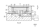
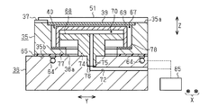
図5に示すように、支持部36には、空気が流動可能な空気流路64が、移動部35を支持する支持面36aに開口するように形成されている。また、移動部35において支持部36に支持される被支持面35bは、金属に比べて摩擦係数が小さく滑りやすい例えば樹脂性の滑り部65により形成されている。
As shown in FIG. 5, an
そして、制動機構40は、プレート39と支持部36との間に形成された収容空間67に収容されている。この制動機構40は、支持部36に固定されたピストン68と、ピストン68に対して高さ方向Zに相対移動可能に設けられたシリンダー69とを備えている。さらに、制動機構40は、ピストン68とシリンダー69とにより形成される容積可変の流体室70と、流体の一例である空気を加圧する変圧機構の一例である加圧機構71と流体室70とを接続する接続流路72とを備えている。なお、加圧機構71には、空気流路64も接続され、空気流路64には、空気の流動を許容もしくは制限する第1弁73aが設けられている。また、接続流路72には、第2弁73bが設けられている。
The
なお、ピストン68とシリンダー69、及び接続流路72は、流体室70の気密性を高めるためにシールされている。また、シリンダー69は、移動部35のX方向及びY方向の移動を許容するように収容空間67の周壁と隙間を有して設けられている。
The
ピストン68は、ロッド部74の基端に形成された雄ねじ部75が、支持部36に形成された雌ねじ部76に螺合することにより支持部36に固定されている。そして、接続流路72は、雄ねじ部75と雌ねじ部76の軸中心に開口するようにピストン68及び支持部36に形成されている。そのため、ピストン68が支持部36に固定されることによりピストン68に形成された接続流路72と支持部36に形成された接続流路72とが連通する。
The
また、移動部35は、シリンダー69と係合可能な係合部77を有している。係合部77は、平面視で円形状の収容空間67の周壁から中心に向かって突出するように円環状に形成され、高さ方向Zにおいてシリンダー69と支持部36との間に位置している。そして、係合部77においてシリンダー69と接触可能な部分には、移動部35に比べて剛性の高い堅牢部78が設けられている。
Further, the moving
次に穿孔装置11及び調整装置16の電気的構成について説明する。
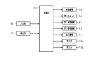
図6に示すように、調整装置16は、第1基準穿孔位置A1もしくは第2基準穿孔位置A2と、相対穿孔位置Bとの理想の間隔である穿孔間隔を入力するための例えばタッチパネルやボタン、外部機器と接続される接続部などの入力部80を備えている。また、調整装置16は、検出部17の検出結果に基づいて第1調整機構41と第2調整機構42とを制御する制御部83を備えている。なお、制御部83は、穿孔ユニット14や加圧機構71など穿孔装置11及び調整装置16における各機構の駆動も統括的に制御する。
Next, the electrical configuration of the
As shown in FIG. 6, the adjusting
すなわち、制御部83は、検出部17により実際に検出された検出位置に基づく検出間隔と、入力された穿孔間隔とに基づいて第1駆動源46及び第2駆動源54の駆動を制御し、第2穿孔ユニット14bの位置を調整する。さらに、制御部83は、加圧機構71、第1弁73a及び第2弁73bの駆動を制御することにより移動部35の移動を制限もしくは許容する。
That is, the
次に第2穿孔ユニット14bを第1穿孔ユニット14aに対して位置合わせする場合の穿孔装置11の作用について説明する。なお、第1穿孔ユニット14aは、第1基準取付部57に取り付けられているものとする。
Next, the operation of the
図1,図2に示すように、第2穿孔ユニット14bは、X方向に大まかに位置決めされた状態で移動部35の上面35aに配置される。さらに、第2穿孔ユニット14bは、案内部37に沿ってY方向に大まかに位置決めされた後、ナット30が締められて移動部35に固定される。そして、制御部83は、移動機構13及び穿孔ユニット14の駆動を制御してワークWに穿孔を行い、さらに穿孔されたワークWを検出部17に撮像させる。
As shown in FIGS. 1 and 2, the
制御部83は、撮像された画像データに基づいて第1基準穿孔位置A1と相対穿孔位置Bとの間隔である検出間隔を取得する。さらに、制御部83は、入力部80により入力された穿孔間隔と検出間隔が異なる場合に、第1駆動源46及び第2駆動源54を駆動して第2穿孔ユニット14bの位置を調整する。
The
すなわち、図3〜図5に示すように、まず制御部83は、第1弁73aを開弁すると共に、第2弁73bを閉弁し、加圧機構71を駆動する。すると、加圧機構71により加圧された空気が空気流路64の開口から噴出し、移動部35と支持部36との摩擦係数が小さくなる。
That is, as shown in FIGS. 3 to 5, the
そして、X方向における検出間隔が穿孔間隔よりも大きい場合には、制御部83は、第1駆動源46を正転駆動する。すると、第1可動部47は、第1駆動源46から離れるようにY方向に沿って移動し、第1可動部47の移動に伴ってスライド部51がX方向に沿って第1基準穿孔位置A1側に移動する。そのため、移動部35は、スライド部51により押圧されて第1基準取付部57側に移動し、移動部35に固定された第2穿孔ユニット14bの相対穿孔位置Bと第1基準穿孔位置A1のX方向における間隔が小さくなる。
When the detection interval in the X direction is larger than the punching interval, the
また、X方向における検出間隔が穿孔間隔よりも小さい場合には、制御部83は、第1駆動源46を逆転駆動する。すると、第1可動部47は、第1駆動源46に近づくようにY方向に沿って移動し、第1可動部47の移動に伴ってスライド部51は、X方向に沿って第2基準穿孔位置A2側に移動する。そのため、スライド部51は、移動部35及び移動部35に固定された第2穿孔ユニット14bを第1穿孔ユニット14aから離れる方向に牽引し、第1基準穿孔位置A1と相対穿孔位置BのX方向における間隔が大きくなる。
When the detection interval in the X direction is smaller than the punching interval, the
一方、Y方向における第2穿孔ユニット14bの位置を調整する場合には、制御部83は、第2駆動源54を駆動する。すなわち、第2駆動源54を正転駆動すると、第2可動部55、移動部35、及び第2穿孔ユニット14bは、第2駆動源54から離れるようにY方向に沿って移動する。また、第2駆動源を逆転駆動すると、第2可動部55、移動部35、及び第2穿孔ユニット14bは、第2駆動源54に近づくようにY方向に沿って移動する。
On the other hand, when adjusting the position of the
図5に示すように、第2穿孔ユニット14bの位置決めが完了すると、制御部83は、第1弁73aを閉弁すると共に、第2弁73bを開弁する。すると、加圧機構71により加圧された空気が流体室70内に流入する。そのため、シリンダー69は、流体室70内の圧力が高くなるのに伴って高さ方向Zに直線運動し、堅牢部78及び係合部77を高さ方向Zに沿うように支持部36側に押圧する。すなわち、制動機構40は、移動部35の移動を制限する。
As shown in FIG. 5, when the positioning of the
上記実施形態によれば、以下のような効果を得ることができる。
(1)制動機構40は、高さ方向Zに沿って直線運動して移動部35を支持部36に押し付けることにより、移動部35がX方向及びY方向へ移動するのを抑制しつつ移動部35の移動を制限できる。したがって、相対穿孔位置Bのずれを抑制しつつ位置合わせできる。
According to the above embodiment, the following effects can be obtained.
(1) The
(2)空気流路64に空気を送り込むと、支持面36aに形成された開口から空気が吹き出す。これにより、支持面36aと被支持面35bとの間の摩擦力が低減され、移動部35を容易に移動させることができる。
(2) When air is sent into the
(3)検出部17の検出結果に基づいて制御部83が第1調整機構41と第2調整機構42を制御して移動部35の位置を調整するため、第1基準穿孔位置A1もしくは第2基準穿孔位置A2に対する相対穿孔位置Bの位置合わせを自動で行うことができる。
(3) Since the
(4)流体室70には接続流路72が接続されているため、加圧機構71が流体室70の圧力を変化させると、シリンダー69が高さ方向Zに移動する。そして、シリンダー69が係合部77と係合して移動部35を支持部36に押し付けることにより、移動部35の移動を制限できる。
(4) Since the
(5)例えば高さ方向Zの大きさに制限がある穿孔装置11では、高さ方向Zにおいて第1調整機構41及び第2調整機構42が占める空間が大きいほど穿孔ユニット14を小型化する必要がある。しかし、小型化に伴って穿孔ユニット14の剛性が低下すると、穿孔に伴う振動により穿孔ユニット14が位置ずれしてしまう虞がある。その点、第1調整機構41と第2調整機構42をX方向に位置をずらして設けたため、例えば高さ方向Zに重ねてX方向に同じ位置に設けた場合に比べて高さ方向Zにおける大きさを小さくできる。
(5) For example, in the
(6)第1基準取付部57と第2基準取付部58とを選択して第1穿孔ユニット14aを基部15に取り付けることにより、第1穿孔ユニット14aと第2穿孔ユニット14bの取り得る間隔を容易に変更できる。
(6) By selecting the first
(7)第2穿孔ユニット14bの穿孔範囲Cは、第1基準穿孔位置A1と第2基準穿孔位置A2との中央と重なる。そのため、第1基準取付部57に取り付けられた第1穿孔ユニット14aと第2穿孔ユニット14bとが取り得る間隔の範囲と、第2基準取付部58に取り付けられた第1穿孔ユニット14aと第2穿孔ユニット14bとが取り得る間隔の範囲を重ねることができる。
(7) The drilling range C of the
(8)例えば、セラミックグリーンシートなどのワークWに穿孔する穿孔装置11のように、マイクロメートル単位の精密な位置決めが要求される穿孔装置11では、わずかなずれでも穿孔ユニット14の位置の調整をやり直さなければならなかった。その点、制動機構40によりX方向やY方向にかかる力を低減した状態で移動部35の移動を制限するため、相対穿孔位置Bのずれを抑制し、容易に位置合わせできる。
(8) For example, in a
なお、上記実施形態は以下のように変更してもよい。
・図7に示すように、シリンダー69は、有底円筒状に形成し、ピストン68を上方から覆うように設けてもよい。さらに、接続流路72は、変圧機構の一例である減圧機構85と流体室70とを接続してもよい(第1変形例)。すなわち、減圧機構85が流体室70内を減圧すると、シリンダー69が係合部77を支持部36側に押圧する。さらに、減圧機構85と空気流路64とを接続してもよい。すなわち、減圧機構85が流体室70内を減圧すると、空気流路64の開口から空気が吸引され、移動部35は支持部36に吸着される。したがって、移動部35の移動をより制限できる。また、空気を加圧もしくは減圧可能なポンプ(変圧機構の一例)に空気流路64と接続流路72とを接続し、移動部35を移動させる場合にはポンプに加圧させ、移動部35の移動を制限する場合にはポンプに減圧させてもよい。
In addition, you may change the said embodiment as follows.
As shown in FIG. 7, the
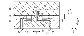
・図8に示すように、支持部36に収容空間67を形成すると共に、ピストン68を移動部35に固定し、さらに接続流路72には加圧機構71を接続してもよい(第2変形例)。すなわち、流体室70が大気開放された状態では、シリンダー69は、図8に2点鎖線で示す位置に位置する。そして、流体室70が加圧されると、シリンダー69は、図8に実線で示す位置に移動して係合部77と係合する。すなわち、制動機構40は、支持部36を移動部35に押し付けることで移動部35の移動を制限する。
As shown in FIG. 8, an
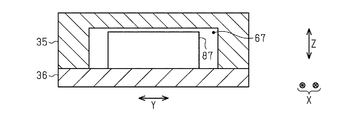
・図9に示すように、制動機構40を電磁石87としてもよい。すなわち、移動部35と支持部36とを電磁石87の磁力で引き合わせることにより、移動部35の移動を制限してもよい。また、制動機構40に加えて電磁石87を設けてもよい。
As shown in FIG. 9, the
・上記実施形態において、制動機構40は、収容空間67にソレノイドを収容し、ソレノイドが備える可動鉄芯を高さ方向Zに沿って直線運動させることにより、移動部35及び支持部36の一方を他方に押し付けてもよい。
In the above embodiment, the
・上記実施形態において、堅牢部78を備えない構成としてもよい。
・上記実施形態において、滑り部65を備えない構成としてもよい。なお、滑り部65は、支持部36の支持面36aに設けてもよく、移動部35の被支持面35bと支持部36の支持面36aの双方に滑り部65を設けてもよい。
In the above embodiment, a configuration without the fastened
In the above embodiment, the sliding
・上記実施形態において、穿孔装置11は、3つ以上の穿孔ユニット14を備えていてもよい。さらに、穿孔装置11は、調整装置16を複数備えていてもよい。
・上記実施形態及び上記変形例において、加圧機構71や減圧機構85は、流動可能な流体(例えば空気などの気体、オイルや水などの液体)を加圧もしくは減圧することにより、シリンダー69を移動させてもよい。
In the above embodiment, the punching
In the embodiment and the modification described above, the
・上記実施形態において、第2穿孔ユニット14bの穿孔範囲Cは、中央位置A3と重なっていなくてもよい。例えば、穿孔範囲Cは、中央位置A3よりも第1基準穿孔位置A1寄り、もしくは中央位置A3よりも第2基準穿孔位置A2寄りとしてもよい。
In the above embodiment, the piercing range C of the second piercing
・上記実施形態において、基部15は、第1基準取付部57と第2基準取付部58の一方を備える構成としてもよい。また、基部15は、3つ以上の基準取付部を備えていてもよい。
In the above embodiment, the
・上記実施形態において、第1調整機構41と第2調整機構42は、X方向において同じ位置に設けてもよい。
・上記実施形態において、第1調整機構41、第2調整機構42、制御部83を備えない構成とし、第2穿孔ユニット14bの位置調整を手動で行った後、制動機構40により移動部35の移動を制限してもよい。
In the above embodiment, the
In the above embodiment, the
・上記実施形態において、調整装置16は、制御部83を備えない構成とし、第1調整機構41及び第2調整機構42の駆動を手動で行ってもよい。
・上記実施形態において、調整装置16は、検出部17を備えない構成とし、制御部83は、入力部80により入力されたX方向及びY方向への調整量に基づいて第1調整機構41及び第2調整機構42を制御してもよい。また、検出部17は、パンチ25の位置を直接検出するセンサーとしてもよい。
In the embodiment described above, the
In the above embodiment, the
・上記実施形態において、空気流路64を設けない構成としてもよい。
・上記実施形態において、空気流路64は、移動部35の被支持面35bに開口するように形成してもよい。また、空気流路64は、移動部の支持面36aと支持部36の支持面の双方の面に開口するように形成してもよい。
In the above embodiment, the
In the above embodiment, the
・上記実施形態において、制動機構40は、ピストン68とシリンダー69を備えず、空気流路64を減圧して支持部36と移動部35を吸着させることにより、移動部35の移動を制限してもよい。
In the above embodiment, the
次に、上記実施形態及び変形例から把握できる技術的思想について以下に追記する。
・技術的思想1
前記制動機構は、前記支持部に固定されたピストンと、該ピストンに対して前記第3方向に相対移動可能に設けられたシリンダーと、前記ピストンと前記シリンダーとにより形成される容積可変の流体室と、流体を加圧もしくは減圧する変圧機構と前記流体室とを接続する接続流路とを備え、前記移動部は、前記シリンダーと係合可能な係合部を有し、該係合部は、前記第3方向において前記シリンダーと前記支持部との間に位置する請求項1〜請求項3のうち何れか一項に記載の穿孔装置。
Next, the technical idea that can be grasped from the above-described embodiment and modifications will be described below.
・ Technical thought 1
The braking mechanism includes a piston fixed to the support portion, a cylinder provided to be movable relative to the piston in the third direction, and a variable volume fluid chamber formed by the piston and the cylinder. And a connecting flow path for connecting the fluid chamber and a pressure-transforming mechanism that pressurizes or depressurizes the fluid, and the moving part has an engaging part engageable with the cylinder, The drilling device according to any one of claims 1 to 3, which is located between the cylinder and the support portion in the third direction.
この構成によれば、流体室には接続流路が接続されているため、変圧機構が流体室の圧力を変化させると、シリンダーが第3方向に移動する。そして、シリンダーが係合部と係合して移動部を支持部に押し付けることにより、移動部の移動を制限できる。 According to this configuration, since the connection flow path is connected to the fluid chamber, the cylinder moves in the third direction when the transformer mechanism changes the pressure of the fluid chamber. Then, the movement of the moving part can be restricted by the cylinder engaging with the engaging part and pressing the moving part against the support part.
・技術的思想2
前記第1調整機構と前記第2調整機構は、前記第1方向に位置をずらして設けられる請求項3に記載の穿孔装置。
・ Technical thought 2
The perforating apparatus according to claim 3, wherein the first adjusting mechanism and the second adjusting mechanism are provided with their positions shifted in the first direction.
例えば第3方向の大きさに制限がある穿孔装置では、第3方向において第1調整機構及び第2調整機構が占める空間が大きいほど穿孔ユニットを小型化する必要がある。しかし、小型化に伴って穿孔ユニットの剛性が低下すると、穿孔に伴う振動により穿孔ユニットが位置ずれしてしまう虞がある。その点、この構成によれば、第1調整機構と第2調整機構を第1方向に位置をずらして設けたため、例えば第3方向に重ねて第1方向に同じ位置に設けた場合に比べて第3方向における大きさを小さくできる。 For example, in a punching device having a size restriction in the third direction, it is necessary to reduce the size of the punching unit as the space occupied by the first adjustment mechanism and the second adjustment mechanism in the third direction increases. However, if the rigidity of the drilling unit decreases with downsizing, the drilling unit may be displaced due to vibrations associated with drilling. In that respect, according to this configuration, since the first adjustment mechanism and the second adjustment mechanism are provided with the positions shifted in the first direction, for example, compared with the case where the first adjustment mechanism and the second adjustment mechanism are overlapped in the third direction and provided in the same position in the first direction. The size in the third direction can be reduced.
・技術的思想3
前記第1穿孔ユニットを取り付け可能な第1基準取付部及び第2基準取付部と、前記第1方向において前記第1基準取付部と前記第2基準取付部の間に位置し前記支持部を取り付け可能な取付部とを有する基部をさらに備える請求項1〜請求項3、技術的思想1及び技術的思想2のうち何れか1つに記載の穿孔装置。
・ Technical thought 3
A first reference attachment portion and a second reference attachment portion to which the first drilling unit can be attached; and the support portion is attached between the first reference attachment portion and the second reference attachment portion in the first direction. The drilling device according to any one of claims 1 to 3, the technical idea 1, and the technical idea 2, further comprising a base portion having a possible attachment portion.
この構成によれば、第1基準取付部と第2基準取付部とを選択して第1穿孔ユニットを基部に取り付けることにより、第1穿孔ユニットと第2穿孔ユニットの取り得る間隔を容易に変更できる。 According to this structure, the space | interval which the 1st drilling unit and the 2nd drilling unit can take is easily changed by selecting a 1st reference attachment part and a 2nd reference attachment part, and attaching a 1st drilling unit to a base. it can.
・技術的思想4
前記第2穿孔ユニットが前記ワークに穿孔する第2穿孔位置が位置可能な穿孔範囲は、前記第1方向において前記第1基準取付部に取り付けられた前記第1穿孔ユニットが前記ワークに穿孔する第1基準穿孔位置と、前記第2基準取付部に取り付けられた前記第1穿孔ユニットが前記ワークに穿孔する第2基準穿孔位置との中央と重なる技術的思想3に記載の穿孔装置。
・ Technical thought 4
The drilling range where the second drilling position where the second drilling unit drills the workpiece is the first drilling unit attached to the first reference mounting portion in the first direction. 4. The punching device according to the technical concept 3, wherein the first reference drilling position and the center of the second reference drilling position in which the first drilling unit attached to the second reference attachment portion punches the workpiece overlaps.
この構成によれば、第2穿孔ユニットの穿孔範囲は、第1基準穿孔位置と第2基準穿孔位置との中央と重なる。そのため、第1基準取付部に取り付けられた第1穿孔ユニットと第2穿孔ユニットとが取り得る間隔の範囲と、第2基準取付部に取り付けられた第1穿孔ユニットと第2穿孔ユニットとが取り得る間隔の範囲を重ねることができる。 According to this configuration, the drilling range of the second drilling unit overlaps the center between the first reference drilling position and the second reference drilling position. Therefore, the range of the distance that can be taken by the first drilling unit and the second drilling unit attached to the first reference mounting part, and the first drilling unit and the second drilling unit attached to the second reference mounting part are taken. The range of the obtained intervals can be overlapped.
・技術的思想5
ワークに穿孔を行う第1穿孔ユニット及び第2穿孔ユニットの間隔を調整する調整装置であって、前記第2穿孔ユニットが固定され第1方向及び該第1方向と交差する第2方向のそれぞれに移動可能な移動部と、該移動部を移動可能に支持する支持部と、前記第1方向及び前記第2方向の双方と交差する第3方向に沿って直線運動して前記移動部及び前記支持部の一方を他方に押し付けることで前記移動部の移動を制限する制動機構とを備える調整装置。
・
An adjusting device for adjusting a distance between a first drilling unit and a second drilling unit for drilling a work, wherein the second drilling unit is fixed in each of a first direction and a second direction intersecting the first direction. A movable part that can move, a support part that movably supports the movable part, and a linear movement along a third direction that intersects both the first direction and the second direction, and the movable part and the support And a braking mechanism that restricts movement of the moving unit by pressing one of the units against the other.
この構成によれば、請求項1に記載の穿孔装置と同様の作用効果を奏し得る。 According to this configuration, the same function and effect as the perforating apparatus according to claim 1 can be obtained.
11…穿孔装置、14a…第1穿孔ユニット、14b…第2穿孔ユニット、17…検出部、35…移動部、35b…被支持面、36…支持部、36a…支持面、40…制動機構、41…第1調整機構、42…第2調整機構、64…空気流路、83…制御部、A1…第1基準穿孔位置(第1穿孔位置の一例)、A2…第2基準穿孔位置(第1穿孔位置の一例)、B…相対穿孔位置(第2穿孔位置の一例)、W…ワーク、Z…高さ方向(第3方向の一例)。
DESCRIPTION OF
Claims (3)
第1方向及び該第1方向と交差する第2方向のそれぞれに移動可能な移動部と、
該移動部を移動可能に支持する支持部と、
前記移動部に固定されて該移動部と共に移動可能であって前記ワークに穿孔を行う第2穿孔ユニットと、
前記第1方向及び前記第2方向の双方と交差する第3方向に沿って直線運動して前記移動部及び前記支持部の一方を他方に押し付けることで前記移動部の移動を制限する制動機構と
を備える穿孔装置。 A first drilling unit for drilling a workpiece;
A moving part movable in each of a first direction and a second direction intersecting the first direction;
A support portion for movably supporting the moving portion;
A second drilling unit fixed to the moving unit and movable with the moving unit and for drilling the workpiece;
A braking mechanism that linearly moves along a third direction that intersects both the first direction and the second direction and restricts movement of the moving unit by pressing one of the moving unit and the support unit against the other; A drilling device comprising:
空気が流動可能な空気流路が開口する請求項1に記載の穿孔装置。 At least one of the support surface that supports the moving unit in the support unit and the supported surface that is supported by the support unit in the moving unit,
The perforating apparatus according to claim 1, wherein an air flow path through which air can flow opens.
前記移動部の前記第1方向における位置を調整する第1調整機構と、
前記移動部の前記第2方向における位置を調整する第2調整機構と、
前記検出部の検出結果に基づいて前記第1調整機構と前記第2調整機構とを制御する制御部と
をさらに備える請求項1又は請求項2に記載の穿孔装置。 A detection unit for detecting a first drilling position at which the first drilling unit drills the workpiece and a second drilling position at which the second drilling unit drills the workpiece;
A first adjustment mechanism for adjusting the position of the moving unit in the first direction;
A second adjustment mechanism for adjusting the position of the moving unit in the second direction;
The punching device according to claim 1 or 2, further comprising: a control unit that controls the first adjustment mechanism and the second adjustment mechanism based on a detection result of the detection unit.
Priority Applications (1)
| Application Number | Priority Date | Filing Date | Title |
|---|---|---|---|
| JP2016092607A JP6709912B2 (en) | 2016-05-02 | 2016-05-02 | Punching device |
Applications Claiming Priority (1)
| Application Number | Priority Date | Filing Date | Title |
|---|---|---|---|
| JP2016092607A JP6709912B2 (en) | 2016-05-02 | 2016-05-02 | Punching device |
Publications (2)
| Publication Number | Publication Date |
|---|---|
| JP2017200711A true JP2017200711A (en) | 2017-11-09 |
| JP6709912B2 JP6709912B2 (en) | 2020-06-17 |
Family
ID=60264500
Family Applications (1)
| Application Number | Title | Priority Date | Filing Date |
|---|---|---|---|
| JP2016092607A Active JP6709912B2 (en) | 2016-05-02 | 2016-05-02 | Punching device |
Country Status (1)
| Country | Link |
|---|---|
| JP (1) | JP6709912B2 (en) |
Cited By (1)
| Publication number | Priority date | Publication date | Assignee | Title |
|---|---|---|---|---|
| JP2019195887A (en) * | 2018-05-11 | 2019-11-14 | コニカミノルタ株式会社 | Perforation processing device and image formation system |
Citations (7)
| Publication number | Priority date | Publication date | Assignee | Title |
|---|---|---|---|---|
| JPS5041183U (en) * | 1973-08-10 | 1975-04-25 | ||
| JPS5993833U (en) * | 1982-12-17 | 1984-06-26 | 株式会社妙徳 | Mobile fixation device |
| JPH0985690A (en) * | 1995-09-22 | 1997-03-31 | U H T Kk | Perforator |
| JPH09295077A (en) * | 1996-05-10 | 1997-11-18 | Mitsubishi Heavy Ind Ltd | Air levitating mold changer |
| JPH10217198A (en) * | 1997-02-05 | 1998-08-18 | U H T Kk | Perforator |
| JP2000190294A (en) * | 1998-12-28 | 2000-07-11 | Uht Corp | Punching device and punching unit used therefor |
| JP2007136670A (en) * | 1998-06-01 | 2007-06-07 | Comercial Industrial Maquinaria Carton Ondulado Sa (Cimcosa) | Device for fixing rotary cutting die in machine for die cutting laminated material |
-
2016
- 2016-05-02 JP JP2016092607A patent/JP6709912B2/en active Active
Patent Citations (7)
| Publication number | Priority date | Publication date | Assignee | Title |
|---|---|---|---|---|
| JPS5041183U (en) * | 1973-08-10 | 1975-04-25 | ||
| JPS5993833U (en) * | 1982-12-17 | 1984-06-26 | 株式会社妙徳 | Mobile fixation device |
| JPH0985690A (en) * | 1995-09-22 | 1997-03-31 | U H T Kk | Perforator |
| JPH09295077A (en) * | 1996-05-10 | 1997-11-18 | Mitsubishi Heavy Ind Ltd | Air levitating mold changer |
| JPH10217198A (en) * | 1997-02-05 | 1998-08-18 | U H T Kk | Perforator |
| JP2007136670A (en) * | 1998-06-01 | 2007-06-07 | Comercial Industrial Maquinaria Carton Ondulado Sa (Cimcosa) | Device for fixing rotary cutting die in machine for die cutting laminated material |
| JP2000190294A (en) * | 1998-12-28 | 2000-07-11 | Uht Corp | Punching device and punching unit used therefor |
Cited By (2)
| Publication number | Priority date | Publication date | Assignee | Title |
|---|---|---|---|---|
| JP2019195887A (en) * | 2018-05-11 | 2019-11-14 | コニカミノルタ株式会社 | Perforation processing device and image formation system |
| JP7081293B2 (en) | 2018-05-11 | 2022-06-07 | コニカミノルタ株式会社 | Perforation processing equipment and image formation system |
Also Published As
| Publication number | Publication date |
|---|---|
| JP6709912B2 (en) | 2020-06-17 |
Similar Documents
| Publication | Publication Date | Title |
|---|---|---|
| CN212886289U (en) | Auxiliary support device and machine tool fixture | |
| JP2014515315A (en) | Machine tools in the form of presses for machining workpieces, especially metal sheets | |
| JP6662467B2 (en) | Press brake | |
| TW201718124A (en) | Punching device | |
| JP2010082753A (en) | Workpiece pressing-in device | |
| EP2011684A3 (en) | Operator's seat for heavy equipment having optimized switch arrangements for controlling the equipment | |
| JP4522826B2 (en) | Electronic component crimping equipment | |
| JP6709912B2 (en) | Punching device | |
| CN104117570A (en) | Metal plate punching device | |
| JP2015020196A (en) | Plate material feeding device | |
| CN201516464U (en) | Channel steel punching machine | |
| CN104718051A (en) | Lifting apparatus having a toggle lever mechanism | |
| CN108215312B (en) | Pressure equipment | |
| EP2151285A1 (en) | Cam device | |
| CN108747262A (en) | A kind of normally close valve press-loading device | |
| KR101562358B1 (en) | Swash cam device for press | |
| JP4995031B2 (en) | Forging machine | |
| JP2005131763A (en) | Clamp device and table positioning device equipped with the same | |
| JP6821476B2 (en) | Blockage forging device | |
| JP2006320934A (en) | Press machine | |
| CN109060277A (en) | A kind of airtight test machine | |
| JP2007118017A (en) | Double-action press device and press method | |
| JPH07256343A (en) | Method for bending plate material and apparatus used for the method | |
| CN105689502A (en) | Metal plate punching device based on clamping pressure detection and laser positioning | |
| JP5385622B2 (en) | Locate clamp device and work panel clamping method |
Legal Events
| Date | Code | Title | Description |
|---|---|---|---|
| A621 | Written request for application examination |
Free format text: JAPANESE INTERMEDIATE CODE: A621 Effective date: 20190408 |
|
| A977 | Report on retrieval |
Free format text: JAPANESE INTERMEDIATE CODE: A971007 Effective date: 20200127 |
|
| A131 | Notification of reasons for refusal |
Free format text: JAPANESE INTERMEDIATE CODE: A131 Effective date: 20200204 |
|
| A521 | Request for written amendment filed |
Free format text: JAPANESE INTERMEDIATE CODE: A523 Effective date: 20200325 |
|
| TRDD | Decision of grant or rejection written | ||
| A01 | Written decision to grant a patent or to grant a registration (utility model) |
Free format text: JAPANESE INTERMEDIATE CODE: A01 Effective date: 20200414 |
|
| A61 | First payment of annual fees (during grant procedure) |
Free format text: JAPANESE INTERMEDIATE CODE: A61 Effective date: 20200422 |
|
| R150 | Certificate of patent or registration of utility model |
Ref document number: 6709912 Country of ref document: JP Free format text: JAPANESE INTERMEDIATE CODE: R150 |
|
| R250 | Receipt of annual fees |
Free format text: JAPANESE INTERMEDIATE CODE: R250 |
|
| R250 | Receipt of annual fees |
Free format text: JAPANESE INTERMEDIATE CODE: R250 |
|
| R250 | Receipt of annual fees |
Free format text: JAPANESE INTERMEDIATE CODE: R250 |
|
| R250 | Receipt of annual fees |
Free format text: JAPANESE INTERMEDIATE CODE: R250 |