JP2017200714A - Cutting device of rubber material and cutting method of the rubber material - Google Patents
Cutting device of rubber material and cutting method of the rubber material Download PDFInfo
- Publication number
- JP2017200714A JP2017200714A JP2016093100A JP2016093100A JP2017200714A JP 2017200714 A JP2017200714 A JP 2017200714A JP 2016093100 A JP2016093100 A JP 2016093100A JP 2016093100 A JP2016093100 A JP 2016093100A JP 2017200714 A JP2017200714 A JP 2017200714A
- Authority
- JP
- Japan
- Prior art keywords
- rubber material
- cutter blade
- cutting
- heater
- cutter
- Prior art date
- Legal status (The legal status is an assumption and is not a legal conclusion. Google has not performed a legal analysis and makes no representation as to the accuracy of the status listed.)
- Granted
Links
Images


Landscapes
- Details Of Cutting Devices (AREA)
- Nonmetal Cutting Devices (AREA)
- Tyre Moulding (AREA)
Abstract
【課題】カット面が荒れることなく短時間で切断することができるゴム材料のカット装置及びカット方法を提供する。【解決手段】カッター刃を移動させながらゴム材料をカットするゴム材料のカット装置であって、刃先がゴム材料に向けられたカッター刃を、ゴム材料の幅方向及び厚み方向に同時に移動させながらゴム材料をカットするカッター移動機構を備えているゴム材料のカット装置。カッター移動機構が、カッター刃を前記ゴム材料の幅方向に移動させる横行機構と、カッター刃を前記ゴム材料の厚み方向に移動させる昇降機構とを備えており、昇降機構と横行機構とを同時に稼働させることによりゴム材料をカットするように構成されているゴム材料のカット装置。【選択図】図1An object of the present invention is to provide a rubber material cutting device and a cutting method which can cut in a short time without roughening a cut surface. A rubber material cutting device for cutting a rubber material while moving a cutter blade, the rubber material being moved while simultaneously moving a cutter blade having a blade edge directed to the rubber material in a width direction and a thickness direction of the rubber material. A rubber material cutting device equipped with a cutter moving mechanism that cuts material. The cutter moving mechanism includes a traversing mechanism that moves the cutter blade in the width direction of the rubber material, and an elevating mechanism that moves the cutter blade in the thickness direction of the rubber material, and simultaneously operates the elevating mechanism and the traversing mechanism. A rubber material cutting device configured to cut the rubber material by causing the device to cut. [Selection diagram] Fig. 1
Description
本発明は、空気入りタイヤの製造に使用されるゴム材料のカット装置および前記ゴム材料のカット装置を用いたゴム材料のカット方法に関する。 The present invention relates to a rubber material cutting device used for manufacturing a pneumatic tire and a rubber material cutting method using the rubber material cutting device.
空気入りタイヤの製造においては、長尺のゴム材料を所定の長さにカットし、カットされたゴム材料を円筒状の成形ドラムに巻回し、カット面同士をジョイントすることが行われている(例えば、特許文献1)。 In the production of a pneumatic tire, a long rubber material is cut into a predetermined length, the cut rubber material is wound around a cylindrical molding drum, and the cut surfaces are joined to each other ( For example, Patent Document 1).
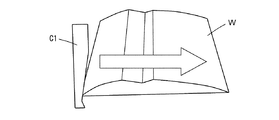
図4は従来のカット方法の一例を説明する斜視図である。図4に示すカット方法では、加熱されたカッター刃C1をゴム材料Wの幅方向(図4中の矢印の方向)に移動させることによりゴム材料Wをカットする。この方法の場合、ゴム材料Wを横切るのに時間が掛かってしまい、タイヤの生産性が悪くなる上に、カット中にカッター刃C1の温度が低下してカット面が荒れる恐れがあった。 FIG. 4 is a perspective view for explaining an example of a conventional cutting method. In the cutting method shown in FIG. 4, the rubber material W is cut by moving the heated cutter blade C1 in the width direction of the rubber material W (the direction of the arrow in FIG. 4). In the case of this method, it takes time to cross the rubber material W, and the productivity of the tire is deteriorated. Further, the temperature of the cutter blade C1 is lowered during cutting, and the cut surface may be roughened.
長尺のゴム材料のカットには、図5に示すような方法も行われている。図5は従来のカット方法の他の例を説明する斜視図である。図5に示すカット方法では、刃先が下方に向けられたカッター刃C2をゴム材料Wの上方に配置し、ゴム材料Wの厚み方向(図5中の矢印の方向)に移動させてカットする。この方法の場合、図4に示す方法よりも短時間でゴム材料をカットすることができる。 For cutting a long rubber material, a method as shown in FIG. 5 is also performed. FIG. 5 is a perspective view for explaining another example of the conventional cutting method. In the cutting method shown in FIG. 5, the cutter blade C2 whose blade edge is directed downward is arranged above the rubber material W, and is moved and cut in the thickness direction of the rubber material W (the direction of the arrow in FIG. 5). In the case of this method, the rubber material can be cut in a shorter time than the method shown in FIG.
しかしながら、上記した図5に示すカット方法を用いた場合、カッター刃C2とゴム材料Wの摩擦により、カット後のゴム材料のカット面が荒れる可能性が高くなる。このように、従来の技術ではいずれのカット方法を用いても、カットに要する時間の短縮化と、カット面の荒れの防止の両方を満足させることが困難であった。 However, when the cutting method shown in FIG. 5 is used, there is a high possibility that the cut surface of the rubber material after cutting is rough due to friction between the cutter blade C2 and the rubber material W. As described above, in any of the conventional techniques, it is difficult to satisfy both the shortening of the time required for cutting and the prevention of roughening of the cut surface, regardless of which cutting method is used.
そこで、本発明は、カットに要する時間を短縮化すると共に、カット面の荒れを防止することができるゴム材料のカット装置及びカット方法を提供することを課題とする。 Accordingly, an object of the present invention is to provide a rubber material cutting device and a cutting method capable of shortening the time required for cutting and preventing roughening of the cut surface.
請求項1に記載の発明は、
カッター刃を移動させながらゴム材料をカットするゴム材料のカット装置であって、
刃先が前記ゴム材料に向けられた前記カッター刃を、前記ゴム材料の幅方向及び厚み方向に同時に移動させながら前記ゴム材料をカットするカッター移動機構を備えていることを特徴とするゴム材料のカット装置である。
The invention described in claim 1
A rubber material cutting device for cutting rubber material while moving a cutter blade,
A rubber material cut comprising a cutter moving mechanism for cutting the rubber material while simultaneously moving the cutter blade whose blade edge is directed to the rubber material in the width direction and the thickness direction of the rubber material. Device.
請求項2に記載の発明は、
前記カッター移動機構が、
前記カッター刃を前記ゴム材料の幅方向に移動させる横行機構と、
前記カッター刃を前記ゴム材料の厚み方向に移動させる昇降機構と
を備えており、
前記横行機構と前記昇降機構とを同時に稼働させることにより前記ゴム材料をカットするように構成されていることを特徴とする請求項1に記載のゴム材料のカット装置である。
The invention described in claim 2
The cutter moving mechanism is
A traversing mechanism for moving the cutter blade in the width direction of the rubber material;
An elevating mechanism for moving the cutter blade in the thickness direction of the rubber material,
2. The rubber material cutting device according to claim 1, wherein the rubber material is cut by operating the traversing mechanism and the elevating mechanism at the same time.
請求項3に記載の発明は、
前記横行機構の横行軸に、前記カッター刃が取り付けられていることを特徴とする請求項2に記載のゴム材料のカット装置である。
The invention according to
The rubber material cutting device according to claim 2, wherein the cutter blade is attached to a transverse axis of the transverse mechanism.
請求項4に記載の発明は、
前記昇降機構の昇降軸に、前記カッター刃が取り付けられていることを特徴とする請求項2に記載のゴム材料のカット装置である。
The invention according to
The rubber material cutting device according to claim 2, wherein the cutter blade is attached to a lifting shaft of the lifting mechanism.
請求項5に記載の発明は、
カット後の前記ゴム材料のカット面が厚み方向に対して鋭角になるように、前記カッター刃を傾けることを特徴とする請求項1ないし請求項4のいずれか1項に記載のゴム材料のカット装置である。
The invention described in claim 5
The rubber material cut according to any one of claims 1 to 4, wherein the cutter blade is inclined so that a cut surface of the rubber material after the cutting has an acute angle with respect to a thickness direction. Device.
請求項6に記載の発明は、
前記昇降機構の昇降軸が、前記ゴム材料の厚み方向に対して傾斜しており、
カット後の前記ゴム材料のカット面が厚み方向に対して鋭角になるように、前記カッター刃を移動させるように構成されていることを特徴とする請求項2ないし請求項4のいずれか1項に記載のゴム材料のカット装置である。
The invention described in claim 6
The lifting shaft of the lifting mechanism is inclined with respect to the thickness direction of the rubber material,
5. The structure according to claim 2, wherein the cutter blade is moved so that a cut surface of the rubber material after the cutting has an acute angle with respect to the thickness direction. The rubber material cutting device described in 1. above.
請求項7に記載の発明は、
前記カッター刃の刃先を加熱するヒーターが、前記カッター移動機構に取り付けられていることを特徴とする請求項1ないし請求項6のいずれか1項に記載のゴム材料のカット装置である。
The invention described in claim 7
The rubber material cutting device according to any one of claims 1 to 6, wherein a heater for heating a blade edge of the cutter blade is attached to the cutter moving mechanism.
請求項8に記載の発明は、
前記ヒーターを前記カッター刃の刃先に近接または離間させるヒーター移動機構を備えており、
前記ヒーター移動機構が、前記ゴム材料のカット前に前記ヒーターを前記刃先に近接させて前記刃先を直接加熱し、前記ゴム材料のカット時に前記ヒーターを前記刃先から離間させるように構成されていることを特徴とする請求項7に記載のゴム材料のカット装置である。
The invention according to claim 8 provides:
A heater moving mechanism for moving the heater close to or away from the blade edge of the cutter blade;
The heater moving mechanism is configured to heat the blade edge directly by bringing the heater close to the blade edge before cutting the rubber material, and to separate the heater from the blade edge when the rubber material is cut. The rubber material cutting device according to claim 7.
請求項9に記載の発明は、
前記ヒーター移動機構が、前記ヒーターを前記カッター刃の刃先に0〜10mmの距離まで近接させるように構成されていることを特徴とする請求項8に記載のゴム材料のカット装置である。
The invention according to claim 9 is:
9. The rubber material cutting device according to claim 8, wherein the heater moving mechanism is configured to bring the heater close to a cutting edge of the cutter blade up to a distance of 0 to 10 mm.
請求項10に記載の発明は、
請求項1ないし請求項9のいずれか1項に記載のゴム材料のカット装置を用いてゴム材料をカットするゴム材料のカット方法であって、
刃先が前記ゴム材料を向いた前記カッター刃を、前記ゴム材料の幅方向及び厚み方向に同時に移動させながら前記ゴム材料をカットすることを特徴とするゴム材料のカット方法である。
The invention according to claim 10 is:
A rubber material cutting method for cutting a rubber material using the rubber material cutting device according to any one of claims 1 to 9,
A rubber material cutting method, wherein the rubber material is cut while simultaneously moving the cutter blade whose blade edge faces the rubber material in the width direction and the thickness direction of the rubber material.
請求項11に記載の発明は、
前記カッター刃を、前記ゴム材料の幅方向に沿って一方向に横行させながら厚み方向に下降させることにより前記ゴム材料をカットすることを特徴とする請求項10に記載のゴム材料のカット方法である。
The invention according to claim 11
The rubber material cutting method according to claim 10, wherein the rubber material is cut by lowering the cutter blade in the thickness direction while traversing in one direction along the width direction of the rubber material. is there.
本発明によれば、カットに要する時間を短縮化すると共に、カット面の荒れを防止することができるゴム材料のカット装置及びカット方法を提供することができる。 According to the present invention, it is possible to provide a rubber material cutting device and a cutting method capable of shortening the time required for cutting and preventing roughening of the cut surface.
以下、本発明を実施の形態に基づき、図面を用いて説明する。 Hereinafter, the present invention will be described with reference to the drawings based on embodiments.
1.本実施の形態に係るゴム材料のカット装置
図1は本実施の形態に係るゴム材料のカット装置(以下、単に「カット装置」ともいう)を示す正面図である。本実施の形態に係るカット装置は、カッター刃Cと、カッター刃Cを移動させるカッター移動機構1を備えている。
1. Rubber Material Cutting Device According to the Present Embodiment FIG. 1 is a front view showing a rubber material cutting device (hereinafter also simply referred to as “cut device”) according to the present embodiment. The cutting device according to the present embodiment includes a cutter blade C and a cutter moving mechanism 1 that moves the cutter blade C.
(1)カッター刃
図1に示すように、本実施の形態に係るカット装置は、図5に示す従来のカット方法に用いられるカット装置と同様に、刃先が下方に向けられたカッター刃Cがゴム材料(図示省略)の上方に配置されている。
(1) Cutter Blade As shown in FIG. 1, the cutting device according to the present embodiment has a cutter blade C whose blade edge is directed downward, similarly to the cutting device used in the conventional cutting method shown in FIG. 5. It is disposed above a rubber material (not shown).
(2)カッター移動機構
そして、本実施の形態に係るカット装置は、上記したカッター刃Cをゴム材料の幅方向(横方向)及び厚み方向(縦方向)に同時に移動させながらゴム材料をカットするカッター移動機構1を備えている点が従来と異なる。
(2) Cutter moving mechanism The cutting device according to the present embodiment cuts the rubber material while simultaneously moving the cutter blade C in the width direction (lateral direction) and the thickness direction (longitudinal direction) of the rubber material. The point provided with the cutter moving mechanism 1 is different from the conventional one.
具体的には、カッター移動機構1は、カッター刃Cを横方向に移動させる横行機構2と、カッター刃Cを縦方向に移動させる昇降機構3とを備えている。
Specifically, the cutter moving mechanism 1 includes a traversing mechanism 2 that moves the cutter blade C in the horizontal direction and an elevating
横行機構2は、カッター刃Cを支持するカッターブラケット2aと、カッターブラケット2aを横方向に案内する横行軸2bと、カッターブラケット2aを横行軸2bに沿って移動させる横送りモータ(図示省略)とを備えており、横送りモータを稼働させることによりカッター刃Cを横方向に移動させる。
The traversing mechanism 2 includes a
昇降機構3は、横行軸2bをスライド可能に支持する支持部材3aと、支持部材3aを縦方向に案内する昇降軸3bと、横行軸2bを昇降軸3bに沿って移動させるための昇降モータ(図示省略)とを備えており、昇降モータを稼働させることにより、カッターブラケット2aを介して横行軸2bに支持されたカッター刃Cを縦方向に移動させる。
The elevating
本実施の形態に係るカット装置は、上記したような横行機構2と昇降機構3を同時に稼働させることにより、カッター刃Cを横方向と縦方向の2軸方向に同時に移動させながらゴム材料をカットする。これにより、カットに要する時間を短縮化すると共に、カット面の荒れを防止することができる。
The cutting device according to the present embodiment cuts the rubber material while simultaneously moving the cutter blade C in the two axial directions of the horizontal direction and the vertical direction by operating the traversing mechanism 2 and the
即ち、本実施の形態によれば、図5に示すカット方法と同様に縦方向にゴム材料Wをカットしているため、図4に示すような横方向にカットする方法よりもカット時間を短縮することができる。 That is, according to the present embodiment, the rubber material W is cut in the vertical direction in the same manner as the cutting method shown in FIG. 5, and therefore the cutting time is shortened compared with the method of cutting in the horizontal direction as shown in FIG. can do.
そして、カッター刃Cを縦方向と同時に横方向に移動させているため、図5に示す従来のカット方法のようにゴム材料を押し切るのではなく、カッター刃を引きながらカットすることができる。これにより、カッター刃Cとゴム材料との摩擦を軽減してカット後のゴム材料のカット面が荒れることを防止することができる。 Since the cutter blade C is moved in the horizontal direction at the same time as the vertical direction, the cutting can be performed while pulling the cutter blade instead of pushing out the rubber material as in the conventional cutting method shown in FIG. Thereby, the friction between the cutter blade C and the rubber material can be reduced, and the cut surface of the rubber material after cutting can be prevented from being rough.
なお、本実施の形態においては、カッター刃を縦方向(ゴム材料の厚み方向)に移動させているが、昇降軸3bを縦方向に対して傾けるとより好ましい。これにより、カット後のゴム材料のカット面が厚み方向に対して鋭角になるため、カット面同士をジョイントした際にジョイント部分に生じる凸部を小さくして、品質の高い空気入りタイヤを製造することができる。
In the present embodiment, the cutter blade is moved in the vertical direction (the thickness direction of the rubber material), but it is more preferable that the lifting
一般に、ゴム材料のカット面が厚み方向に対して鋭角になるようにカッター刃を傾けると、ゴム材料とカッター刃との接触面積が大きくなり、摩擦が大きくなるためカット面が荒れる可能性が高くなる。しかし、本実施の形態に係るカット装置によれば、カッター刃Cとゴム材料との摩擦が大幅に軽減されているため、カッター刃を傾けることにより摩擦が多少増加してもカット面が荒れることがない。 In general, if the cutter blade is tilted so that the cut surface of the rubber material becomes an acute angle with respect to the thickness direction, the contact area between the rubber material and the cutter blade increases, and the friction increases and the cut surface is likely to be rough. Become. However, according to the cutting device according to the present embodiment, since the friction between the cutter blade C and the rubber material is greatly reduced, even if the friction increases slightly by tilting the cutter blade, the cut surface becomes rough. There is no.
2.他の実施の形態に係るゴム材料のカット装置
(1)カッター移動機構の他の例
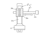
上記した実施の形態においてはカッター刃Cを横行機構2の横行軸2bに取り付けているが、カッター刃は、図2に示すカット装置のように昇降機構31に取り付けてもよい。
2. Rubber Material Cutting Device According to Other Embodiment (1) Other Examples of Cutter Moving Mechanism In the above-described embodiment, the cutter blade C is attached to the
具体的には、図2に示すカット装置では、カッター刃Cを支持するカッターブラケット31aが昇降機構31の昇降軸31bに取り付けられており、昇降軸31bを支持する支持部材21aが横行機構21の横行軸21bにスライド可能に支持されている。
Specifically, in the cutting apparatus shown in FIG. 2, the
このような構造のカット装置を用いた場合でも、カッター刃Cを横方向と縦方向の2軸方向に同時に移動させることができるため、カットに要する時間を短縮化すると共に、カット後のゴム材料のカット面の荒れを防止することができる。 Even when the cutting device having such a structure is used, the cutter blade C can be moved simultaneously in the two axial directions of the horizontal direction and the vertical direction. Roughness of the cut surface can be prevented.
(2)ヒーター移動機構
本発明者は、ゴム材料のカット装置に改良の余地が残されていないかについて、さらに検討した結果、カッター刃を加熱するヒーターを改良することに思い至った。
(2) Heater moving mechanism As a result of further examination as to whether or not there is room for improvement in the rubber material cutting device, the inventors have come up with the idea of improving the heater for heating the cutter blade.
具体的には、一般なカット装置には、ゴム材料をカットしやすくするためにカッター刃を加熱するヒーターが設けられているが、本発明者の検討の結果、このヒーターについて種々の問題が残っていることが分かった。 Specifically, a general cutting apparatus is provided with a heater that heats the cutter blade in order to make it easy to cut rubber material. I found out.
具体的には、カッター刃を加熱する方法の一つに、カッター刃の根元にヒーターを取り付けて熱伝導でカッター刃の刃先を加熱しながらカットする方法がある。しかし、カッター刃の材料の熱伝導性が低いと、刃先の温度が十分に上昇しなかったり、刃先の温度が不均一になったりして、ゴム材料のカット面が荒れたり、カッター刃に負担が掛かって寿命が短くなるという問題が生じることが分かった。 Specifically, as one of the methods for heating the cutter blade, there is a method in which a heater is attached to the base of the cutter blade and the cutter blade is cut while being heated by heat conduction. However, if the thermal conductivity of the cutter blade material is low, the cutting edge temperature will not rise sufficiently, or the cutting edge temperature will become uneven, and the cut surface of the rubber material will be rough and the cutter blade will be burdened. It has been found that there is a problem that the service life is shortened by applying.
また、カット位置から離れた待機位置にヒーターを設け、ゴム材料のカットを行わない待機状態の間に、カッター刃を待機位置まで移動させて刃先をヒーターに押し当てて直接加熱する方法もある。 There is also a method in which a heater is provided at a standby position away from the cutting position, and the cutter blade is moved to the standby position and pressed directly against the heater during a standby state in which the rubber material is not cut.
しかし、カッター刃がゴム材料をカットすると、刃先の温度が10〜100℃まで低下するため、次回のカットまでに規定の温度(150〜200℃)まで再加熱する必要がある。待機位置にヒーターを設けた場合、カッター刃を待機位置まで移動させないと刃先を加熱することができないため、次のカットを開始するまでの待機時間が長くなることが分かった。 However, when the cutter blade cuts the rubber material, the temperature of the blade tip decreases to 10 to 100 ° C., and therefore it is necessary to reheat to a specified temperature (150 to 200 ° C.) until the next cutting. It was found that when the heater is provided at the standby position, the cutting edge cannot be heated unless the cutter blade is moved to the standby position, so that the standby time until the next cut is started is increased.
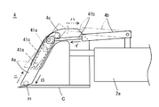
本発明者は、これらのヒーターに関する問題に対応するために、上記した実施の形態に係るカット装置に、図3に示すような構造のヒーターを用いることを考えた。図3は本発明の他の実施の形態に係るカット装置のヒーターを説明する側面図である。 The present inventor considered using a heater having a structure as shown in FIG. 3 in the cutting device according to the above-described embodiment in order to cope with the problems related to these heaters. FIG. 3 is a side view for explaining a heater of a cutting device according to another embodiment of the present invention.
図3に示すように、本実施の形態に係るカット装置は、カッター移動機構1に取り付けられたヒーターHと、ヒーターHをカッター刃Cの刃先に対して近接離間させるヒーター移動機構4を備えている。なお、図3中の実線部分がヒーターHをカッター刃Cに近接させた状態を示し、二点鎖線部分が離間させた状態を示している。
As shown in FIG. 3, the cutting device according to the present embodiment includes a heater H attached to the cutter moving mechanism 1 and a
具体的には、ヒーターHは、ヒーターブラケット4aに取り付けられている。また、ヒーター移動機構4は、ヒーターブラケット4aを移動させるシリンダー4bと移動ガイド4cとを備えている。
Specifically, the heater H is attached to the
そして、本実施の形態においては、ヒーターHが、ヒーターブラケット4aと移動ガイド4cを介して、カッター移動機構1のカッターブラケット2aに取り付けられているため、ヒーターHをカッター刃Cと共に移動させることができる。
And in this Embodiment, since the heater H is attached to the
また、ヒーター移動機構4のシリンダー4bは、基端がカッターブラケット2aにヒンジ連結されており、先端がヒーターブラケット4aにヒンジ連結されている。
The
移動ガイド4cには、へ字状のガイド孔41cが形成されており、ヒーターブラケット4aのガイドピン41aがガイド孔41cに嵌め込まれている。
The moving
このような構造のヒーター移動機構4の場合、図3の矢印イのようにシリンダー4bのロッド41bを伸ばすことにより、矢印ロのようにヒーターブラケット4aをガイド孔41cに沿って移動させて、ヒーターブラケット4a先端のヒーターHをカッター刃Cの刃先に近接させることができる。一方、矢印ハのようにシリンダー4bのロッド41bを縮めることにより、矢印ニのようにヒーターHをカッター刃Cの刃先から離間させることができる。
In the case of the
本実施の形態においては、ヒーターHをカッター刃Cの刃先に近接させて直接加熱することができるため、カッター刃に熱伝導が悪い材料を用いても、カッター刃Cの刃先を十分に加熱できると共に刃先の温度を均一にできる。なお、このときのヒーターHとカッター刃Cの刃先の距離は0〜10mmにすることが好ましい。 In the present embodiment, since the heater H can be directly heated by being brought close to the cutting edge of the cutter blade C, the cutting edge of the cutter blade C can be sufficiently heated even if a material having poor heat conduction is used for the cutter blade. At the same time, the temperature of the blade edge can be made uniform. In addition, it is preferable that the distance of the blade edge | tip of the heater H and the cutter blade C at this time shall be 0-10 mm.
また、ヒーターブラケット4aと移動ガイド4cを介して、ヒーターHがカッター移動機構1のカッターブラケット2aに取り付けられていることにより、ヒーターHをカッター刃Cと共に移動させることができるため、カッター刃Cを待機位置まで移動させなくても加熱することができ、待機位置にヒーターを設置する方法よりも待機時間を短くすることができる。
Further, since the heater H is attached to the
そして、本実施の形態においては、ヒーターHがカッター刃Cの刃先に対して離間できるように構成されており、ゴム材料をカットする際に、ヒーターHをカッター刃Cから離間させる。これにより、ヒーターHをカッター刃Cと共に移動させているにも拘らず、ヒーターHがカット動作の邪魔になることがない。 In this embodiment, the heater H is configured to be separated from the cutting edge of the cutter blade C, and the heater H is separated from the cutter blade C when the rubber material is cut. Thereby, although the heater H is moved with the cutter blade C, the heater H does not interfere with the cutting operation.
以上、本発明を実施の形態に基づいて説明したが、本発明は上記の実施の形態に限定されるものではない。本発明と同一および均等の範囲内において、上記の実施の形態に対して種々の変更を加えることができる。 While the present invention has been described based on the embodiments, the present invention is not limited to the above embodiments. Various modifications can be made to the above-described embodiments within the same and equivalent scope as the present invention.
1 カッター移動機構
2、21 横行機構
2a、31a カッターブラケット
2b、21b 横行軸
3、31 昇降機構
3a、21a 支持部材
3b、31b 昇降軸
4 ヒーター移動機構
4a ヒーターブラケット
4b シリンダー
4c 移動ガイド
41a ガイドピン
41b ロッド
41c ガイド孔
C、C1、C2 カッター刃
H ヒーター
W ゴム材料
DESCRIPTION OF SYMBOLS 1
Claims (11)
刃先が前記ゴム材料に向けられた前記カッター刃を、前記ゴム材料の幅方向及び厚み方向に同時に移動させながら前記ゴム材料をカットするカッター移動機構を備えていることを特徴とするゴム材料のカット装置。 A rubber material cutting device for cutting rubber material while moving a cutter blade,
A rubber material cut comprising a cutter moving mechanism for cutting the rubber material while simultaneously moving the cutter blade whose blade edge is directed to the rubber material in the width direction and the thickness direction of the rubber material. apparatus.
前記カッター刃を前記ゴム材料の幅方向に移動させる横行機構と、
前記カッター刃を前記ゴム材料の厚み方向に移動させる昇降機構と
を備えており、
前記横行機構と前記昇降機構とを同時に稼働させることにより前記ゴム材料をカットするように構成されていることを特徴とする請求項1に記載のゴム材料のカット装置。 The cutter moving mechanism is
A traversing mechanism for moving the cutter blade in the width direction of the rubber material;
An elevating mechanism for moving the cutter blade in the thickness direction of the rubber material,
The rubber material cutting device according to claim 1, wherein the rubber material is cut by simultaneously operating the traversing mechanism and the elevating mechanism.
カット後の前記ゴム材料のカット面が厚み方向に対して鋭角になるように、前記カッター刃を移動させるように構成されていることを特徴とする請求項2ないし請求項4のいずれか1項に記載のゴム材料のカット装置。 The lifting shaft of the lifting mechanism is inclined with respect to the thickness direction of the rubber material,
5. The structure according to claim 2, wherein the cutter blade is moved so that a cut surface of the rubber material after the cutting has an acute angle with respect to the thickness direction. The rubber material cutting device described in 1.
前記ヒーター移動機構が、前記ゴム材料のカット前に前記ヒーターを前記刃先に近接させて前記刃先を直接加熱し、前記ゴム材料のカット時に前記ヒーターを前記刃先から離間させるように構成されていることを特徴とする請求項7に記載のゴム材料のカット装置。 A heater moving mechanism for moving the heater close to or away from the blade edge of the cutter blade;
The heater moving mechanism is configured to directly heat the blade edge by bringing the heater close to the blade edge before cutting the rubber material, and to separate the heater from the blade edge when the rubber material is cut. The rubber material cutting device according to claim 7.
刃先が前記ゴム材料を向いた前記カッター刃を、前記ゴム材料の幅方向及び厚み方向に同時に移動させながら前記ゴム材料をカットすることを特徴とするゴム材料のカット方法。 A rubber material cutting method for cutting a rubber material using the rubber material cutting device according to any one of claims 1 to 9,
A rubber material cutting method, wherein the rubber material is cut while simultaneously moving the cutter blade whose blade edge faces the rubber material in the width direction and the thickness direction of the rubber material.
Priority Applications (1)
| Application Number | Priority Date | Filing Date | Title |
|---|---|---|---|
| JP2016093100A JP6716094B2 (en) | 2016-05-06 | 2016-05-06 | Rubber material cutting device and rubber material cutting method |
Applications Claiming Priority (1)
| Application Number | Priority Date | Filing Date | Title |
|---|---|---|---|
| JP2016093100A JP6716094B2 (en) | 2016-05-06 | 2016-05-06 | Rubber material cutting device and rubber material cutting method |
Publications (2)
| Publication Number | Publication Date |
|---|---|
| JP2017200714A true JP2017200714A (en) | 2017-11-09 |
| JP6716094B2 JP6716094B2 (en) | 2020-07-01 |
Family
ID=60264502
Family Applications (1)
| Application Number | Title | Priority Date | Filing Date |
|---|---|---|---|
| JP2016093100A Expired - Fee Related JP6716094B2 (en) | 2016-05-06 | 2016-05-06 | Rubber material cutting device and rubber material cutting method |
Country Status (1)
| Country | Link |
|---|---|
| JP (1) | JP6716094B2 (en) |
Cited By (4)
| Publication number | Priority date | Publication date | Assignee | Title |
|---|---|---|---|---|
| JP2019198934A (en) * | 2018-05-17 | 2019-11-21 | 住友ゴム工業株式会社 | Cutting apparatus for rubber material |
| JP2020178104A (en) * | 2019-04-22 | 2020-10-29 | リンテック株式会社 | Temperature changing device for cutting means and temperature changing method for cutting means |
| CN113263530A (en) * | 2021-06-21 | 2021-08-17 | 聊城鑫泰机床有限公司 | Automatic production line for PVC (polyvinyl chloride) redundant edge carpet |
| JP2022061914A (en) * | 2020-10-07 | 2022-04-19 | Toyo Tire株式会社 | Veil rubber cutting device |
Citations (7)
| Publication number | Priority date | Publication date | Assignee | Title |
|---|---|---|---|---|
| JPS5884224U (en) * | 1981-12-04 | 1983-06-07 | 日立電線株式会社 | Cutting device for unvulcanized rubber tubes |
| JPS58203033A (en) * | 1982-05-24 | 1983-11-26 | Bridgestone Corp | Unvalcanized rubber sheet cutter |
| JPH0760685A (en) * | 1993-08-26 | 1995-03-07 | Bando Chem Ind Ltd | Band splicer device |
| JP2001205588A (en) * | 2000-01-28 | 2001-07-31 | Yokohama Rubber Co Ltd:The | Method and device for cutting rubber elastic member |
| JP2004066347A (en) * | 2002-08-01 | 2004-03-04 | Horizon International Inc | Cutting operation switching mechanism of cutting machine |
| WO2008153021A1 (en) * | 2007-06-14 | 2008-12-18 | Bridgestone Corporation | Cutting device and cut object producing method |
| JP2015205480A (en) * | 2014-04-22 | 2015-11-19 | 住友ゴム工業株式会社 | Manufacturing method of pneumatic tire |
-
2016
- 2016-05-06 JP JP2016093100A patent/JP6716094B2/en not_active Expired - Fee Related
Patent Citations (7)
| Publication number | Priority date | Publication date | Assignee | Title |
|---|---|---|---|---|
| JPS5884224U (en) * | 1981-12-04 | 1983-06-07 | 日立電線株式会社 | Cutting device for unvulcanized rubber tubes |
| JPS58203033A (en) * | 1982-05-24 | 1983-11-26 | Bridgestone Corp | Unvalcanized rubber sheet cutter |
| JPH0760685A (en) * | 1993-08-26 | 1995-03-07 | Bando Chem Ind Ltd | Band splicer device |
| JP2001205588A (en) * | 2000-01-28 | 2001-07-31 | Yokohama Rubber Co Ltd:The | Method and device for cutting rubber elastic member |
| JP2004066347A (en) * | 2002-08-01 | 2004-03-04 | Horizon International Inc | Cutting operation switching mechanism of cutting machine |
| WO2008153021A1 (en) * | 2007-06-14 | 2008-12-18 | Bridgestone Corporation | Cutting device and cut object producing method |
| JP2015205480A (en) * | 2014-04-22 | 2015-11-19 | 住友ゴム工業株式会社 | Manufacturing method of pneumatic tire |
Cited By (7)
| Publication number | Priority date | Publication date | Assignee | Title |
|---|---|---|---|---|
| JP2019198934A (en) * | 2018-05-17 | 2019-11-21 | 住友ゴム工業株式会社 | Cutting apparatus for rubber material |
| JP7102928B2 (en) | 2018-05-17 | 2022-07-20 | 住友ゴム工業株式会社 | Rubber material cutting device |
| JP2020178104A (en) * | 2019-04-22 | 2020-10-29 | リンテック株式会社 | Temperature changing device for cutting means and temperature changing method for cutting means |
| JP7240942B2 (en) | 2019-04-22 | 2023-03-16 | リンテック株式会社 | Variable temperature device for cutting means and variable temperature method for cutting means |
| JP2022061914A (en) * | 2020-10-07 | 2022-04-19 | Toyo Tire株式会社 | Veil rubber cutting device |
| CN113263530A (en) * | 2021-06-21 | 2021-08-17 | 聊城鑫泰机床有限公司 | Automatic production line for PVC (polyvinyl chloride) redundant edge carpet |
| CN113263530B (en) * | 2021-06-21 | 2024-02-27 | 聊城鑫泰机床有限公司 | Automatic production line for PVC redundant carpet |
Also Published As
| Publication number | Publication date |
|---|---|
| JP6716094B2 (en) | 2020-07-01 |
Similar Documents
| Publication | Publication Date | Title |
|---|---|---|
| JP6716094B2 (en) | Rubber material cutting device and rubber material cutting method | |
| WO2014196127A1 (en) | Method of thickening and forming by spinning and device for thickening and forming by spinning | |
| CN105682857A (en) | Device for sharpening blades | |
| JP2019198934A (en) | Cutting apparatus for rubber material | |
| JP6388327B2 (en) | Cleaning device and soldering system | |
| JP2005538918A (en) | How to cut long glass sheets during flat glass production | |
| JP2010045290A (en) | Air-core coil winding device and control method therefor | |
| JP2009190059A (en) | Method and device for manufacturing spiral spring | |
| JP6441942B2 (en) | Clamping device | |
| JP2011173168A (en) | Bending method of plate member | |
| JP2002113688A (en) | Cutting method and device for cord-inserted rubber sheet | |
| JP6125253B2 (en) | Unvulcanized rubber member cutting apparatus and method | |
| JP6514583B2 (en) | Rubber sheet cutting method and cutting apparatus | |
| JP6461501B2 (en) | Topping device and method for cutting edge portion of topping sheet | |
| JP2009000758A (en) | Grooving cutter | |
| JP6758596B2 (en) | Rubber material cutting device | |
| KR101543879B1 (en) | Sleeve assembling apparatus of plating roll | |
| JP2012171274A (en) | Breaker cutter device | |
| CN102826741B (en) | Positioning device for curved glass moulding and preparation method of curved glass | |
| JP7148869B2 (en) | Glass plate manufacturing method | |
| JP6972988B2 (en) | Cutting method and cutting device for unvulcanized rubber strips | |
| KR101643921B1 (en) | Side guide apparatus capable of materials turning | |
| JP2017177556A (en) | Sidewall holing apparatus and method | |
| JP2013010129A (en) | Method for drawing steel product and die device for drawing steel product | |
| KR200302855Y1 (en) | A trimming cutter heating device |
Legal Events
| Date | Code | Title | Description |
|---|---|---|---|
| A621 | Written request for application examination |
Free format text: JAPANESE INTERMEDIATE CODE: A621 Effective date: 20190320 |
|
| A977 | Report on retrieval |
Free format text: JAPANESE INTERMEDIATE CODE: A971007 Effective date: 20200115 |
|
| A131 | Notification of reasons for refusal |
Free format text: JAPANESE INTERMEDIATE CODE: A131 Effective date: 20200128 |
|
| A521 | Request for written amendment filed |
Free format text: JAPANESE INTERMEDIATE CODE: A523 Effective date: 20200313 |
|
| TRDD | Decision of grant or rejection written | ||
| A01 | Written decision to grant a patent or to grant a registration (utility model) |
Free format text: JAPANESE INTERMEDIATE CODE: A01 Effective date: 20200511 |
|
| A61 | First payment of annual fees (during grant procedure) |
Free format text: JAPANESE INTERMEDIATE CODE: A61 Effective date: 20200524 |
|
| R150 | Certificate of patent or registration of utility model |
Ref document number: 6716094 Country of ref document: JP Free format text: JAPANESE INTERMEDIATE CODE: R150 |
|
| R250 | Receipt of annual fees |
Free format text: JAPANESE INTERMEDIATE CODE: R250 |
|
| R250 | Receipt of annual fees |
Free format text: JAPANESE INTERMEDIATE CODE: R250 |
|
| LAPS | Cancellation because of no payment of annual fees |