JP2017201216A - Turbo refrigerator - Google Patents
Turbo refrigerator Download PDFInfo
- Publication number
- JP2017201216A JP2017201216A JP2016092281A JP2016092281A JP2017201216A JP 2017201216 A JP2017201216 A JP 2017201216A JP 2016092281 A JP2016092281 A JP 2016092281A JP 2016092281 A JP2016092281 A JP 2016092281A JP 2017201216 A JP2017201216 A JP 2017201216A
- Authority
- JP
- Japan
- Prior art keywords
- refrigerant
- electric motor
- liquid refrigerant
- gas
- turbo
- Prior art date
- Legal status (The legal status is an assumption and is not a legal conclusion. Google has not performed a legal analysis and makes no representation as to the accuracy of the status listed.)
- Granted
Links
Images

Landscapes
- Structures Of Non-Positive Displacement Pumps (AREA)
Abstract
Description
本発明は、ターボ冷凍機に係り、特にターボ圧縮機を駆動する電動機に冷凍サイクルか
ら冷媒の一部を導いて電動機を冷却する方式のターボ冷凍機に関するものである。
The present invention relates to a turbo chiller, and more particularly to a turbo chiller that cools an electric motor by introducing a part of refrigerant from a refrigeration cycle to an electric motor that drives the turbo compressor.
従来、冷凍空調装置などに利用されるターボ冷凍機は、冷媒を封入したクローズドシス
テムで構成され、冷水(被冷却流体)から熱を奪って冷媒が蒸発して冷凍効果を発揮する
蒸発器と、前記蒸発器で蒸発した冷媒ガスを圧縮して高圧の冷媒ガスにする圧縮機と、高
圧の冷媒ガスを冷却水(冷却流体)で冷却して凝縮させる凝縮器と、前記凝縮した冷媒を
減圧して膨張させる膨張弁(膨張機構)とを、冷媒配管によって連結して構成されている。
Conventionally, a turbo refrigerator used in a refrigeration air conditioner or the like is configured by a closed system in which a refrigerant is enclosed, an evaporator that takes heat from cold water (fluid to be cooled) and evaporates the refrigerant to exert a refrigeration effect; A compressor that compresses the refrigerant gas evaporated in the evaporator to form a high-pressure refrigerant gas; a condenser that cools and condenses the high-pressure refrigerant gas with cooling water (cooling fluid); and depressurizes the condensed refrigerant. An expansion valve (expansion mechanism) that is expanded by being connected by a refrigerant pipe.
ターボ冷凍機に用いられているターボ圧縮機は、電動機が圧縮機とともに分割型のケー
シングに密閉状態で収容されている半密閉型圧縮機を採用する場合が多い。この半密閉型
圧縮機においては、電動機の損失により生じた発熱を、冷凍サイクル中の凝縮冷媒(液冷
媒)を電動機内部に導入して冷媒の蒸発潜熱を利用して冷却する場合が多い。このように、電動機を液冷媒を用いて冷却する場合、電動機の回転体(ロータ)と過剰に散布された液冷媒とが接触して撹拌損失が大きくなり、その結果、電動機の損失が大きくなるため、冷凍機の効率が低下するという問題点がある。
一方、冷凍サイクル中のガス冷媒を用いて電動機を冷却する場合、ガス冷媒によって電動機から持ち去る熱量が小さいため、高負荷時の所要ガス量が多くなり、その結果、配管径およびモータ内部流路等の冷却用流路が大きくなり、装置が大型化するという問題点がある。
In many cases, a turbo compressor used in a turbo refrigerator employs a semi-hermetic compressor in which an electric motor is housed in a split casing together with a compressor. In this semi-hermetic compressor, the heat generated due to the loss of the electric motor is often cooled by introducing condensed refrigerant (liquid refrigerant) in the refrigeration cycle into the electric motor and using the latent heat of vaporization of the refrigerant. Thus, when the electric motor is cooled using liquid refrigerant, the rotating body (rotor) of the electric motor and the excessively dispersed liquid refrigerant come into contact with each other, resulting in an increase in stirring loss, resulting in an increase in electric motor loss. Therefore, there is a problem that the efficiency of the refrigerator is lowered.
On the other hand, when the electric motor is cooled using the gas refrigerant in the refrigeration cycle, the amount of heat required to be taken away from the electric motor by the gas refrigerant is small, so the required amount of gas at high load increases, resulting in the pipe diameter, motor internal flow path, etc. There is a problem that the cooling flow path becomes larger and the apparatus becomes larger.
本発明は、上述の事情に鑑みなされたもので、ターボ圧縮機を駆動する電動機の冷却用冷媒として冷凍サイクルから電動機に供給される冷媒を、ガス冷媒と液冷媒とを併用可能またはガス冷媒のみとすることができ、撹拌損失を低減させて冷凍機の効率低下を防止することができるターボ冷凍機を提供することを目的とする。 The present invention has been made in view of the above-described circumstances, and the refrigerant supplied to the electric motor from the refrigeration cycle as the refrigerant for cooling the electric motor that drives the turbo compressor can be used in combination with the gas refrigerant and the liquid refrigerant or only the gas refrigerant. An object of the present invention is to provide a turbo refrigerator that can reduce stirring loss and prevent a decrease in efficiency of the refrigerator.
上述の目的を達成するため、本発明のターボ冷凍機は、冷水から熱を奪って冷媒が蒸発し冷凍効果を発揮する蒸発器と、冷媒を羽根車によって圧縮するターボ圧縮機と、ターボ圧縮機を駆動する電動機と、圧縮された冷媒を冷却水で冷却して凝縮させる凝縮器とを備えたターボ冷凍機において、前記凝縮器から前記電動機にガス冷媒を供給するガス冷媒供給配管と、前記凝縮器から前記電動機に液冷媒を供給する液冷媒供給配管とを備え、前記電動機をガス冷媒と液冷媒とを併用して冷却するようにしたことを特徴とする。 In order to achieve the above object, a turbo refrigerator of the present invention includes an evaporator that takes heat from cold water and evaporates the refrigerant to exert a refrigeration effect, a turbo compressor that compresses the refrigerant with an impeller, and a turbo compressor A turbo chiller comprising a motor for driving the compressor and a condenser for cooling and condensing the compressed refrigerant with cooling water, a gas refrigerant supply pipe for supplying gas refrigerant from the condenser to the electric motor, and the condensation And a liquid refrigerant supply pipe for supplying liquid refrigerant to the electric motor from a container, wherein the electric motor is cooled by using a gas refrigerant and a liquid refrigerant together.
本発明の好ましい態様によれば、前記液冷媒供給配管に設置される液冷媒制御弁と、冷凍負荷を検出する手段を備え、ターボ冷凍機の負荷が所定の値よりも小さいときには、前記液冷媒制御弁を閉じ、前記電動機をガス冷媒のみで冷却するようにしたことを特徴とする。
本発明の好ましい態様によれば、前記ガス冷媒供給配管に設置されるガス冷媒制御弁と、冷凍負荷を検出する手段を備え、前記ガス冷媒制御弁を負荷に応じて開度制御することを特徴とする。
本発明の好ましい態様によれば、ターボ冷凍機の負荷が所定の値よりも大きいときには、ガス冷媒流量が100%になるように前記ガス冷媒制御弁を制御し、さらに、前記液冷媒制御弁を前記負荷に応じて制御することを特徴とする。
According to a preferred aspect of the present invention, the liquid refrigerant control valve installed in the liquid refrigerant supply pipe and means for detecting a refrigeration load are provided, and when the load of the turbo chiller is smaller than a predetermined value, the liquid refrigerant The control valve is closed, and the electric motor is cooled only by a gas refrigerant.
According to a preferred aspect of the present invention, a gas refrigerant control valve installed in the gas refrigerant supply pipe and means for detecting a refrigeration load are provided, and the opening degree of the gas refrigerant control valve is controlled according to the load. And
According to a preferred aspect of the present invention, when the load of the centrifugal chiller is larger than a predetermined value, the gas refrigerant control valve is controlled so that the gas refrigerant flow rate becomes 100%, and the liquid refrigerant control valve is further controlled. Control is performed according to the load.
本発明の好ましい態様によれば、負荷が小さい場合に、前記制御弁をホットガスバイパス制御に使用することを特徴とする。
本発明の好ましい態様によれば、前記電動機から排出されるガス冷媒を駆動用ガスとして、前記電動機に溜まっている液冷媒を吸引して該液冷媒を電動機から排出するためのエジェクタを設け、前記エジェクタにより吸引された液冷媒は、前記蒸発器に戻されることを特徴とする。
According to a preferred aspect of the present invention, the control valve is used for hot gas bypass control when the load is small.
According to a preferred aspect of the present invention, there is provided an ejector that uses the gas refrigerant discharged from the electric motor as a driving gas, sucks the liquid refrigerant accumulated in the electric motor, and discharges the liquid refrigerant from the electric motor, The liquid refrigerant sucked by the ejector is returned to the evaporator.
本発明は、以下に列挙する効果を奏する。
1)ターボ圧縮機を駆動する電動機の冷却用冷媒として冷凍サイクルから電動機に供給
される冷媒を、ガス冷媒と液冷媒とを併用可能またはガス冷媒のみとすることができる。したがって、ターボ冷凍機の低負荷時はガス冷媒のみで電動機を冷却することができるため、撹拌損失が小さくて済み、また、凝縮器からエコノマイザを経由せずに蒸発器に流れる液冷媒を減らすことで冷凍機の効率低下を防止することができる。また、高負荷時はガス冷媒と液冷媒とを併用して電動機を冷却することができ、液冷媒をコイルなどの高温部に集中的に散布できるため、冷却能力が不足することはない。
2)ターボ冷凍機の低負荷時はガス冷媒のみで電動機を冷却することができるため、冷媒
ポンプの動力を削減することができる。
3)ターボ冷凍機は低負荷で運転されることが多いので、低負荷時の効率改善は効果的で
ある。
4)ガス冷媒のみでなく、液冷媒を併用することができるため、配管径およびモータ内部流路等の冷却用流路の簡素化を図ることができ、装置を小型化できる。
The present invention has the following effects.
1) As a refrigerant for cooling the electric motor that drives the turbo compressor, the refrigerant supplied from the refrigeration cycle to the electric motor can be used in combination with a gas refrigerant and a liquid refrigerant, or only the gas refrigerant can be used. Therefore, since the electric motor can be cooled only by the gas refrigerant when the turbo chiller is under a low load, the stirring loss is small, and the liquid refrigerant flowing from the condenser to the evaporator without going through the economizer is reduced. Thus, it is possible to prevent the efficiency of the refrigerator from decreasing. Further, when the load is high, the electric motor can be cooled by using both the gas refrigerant and the liquid refrigerant, and the liquid refrigerant can be intensively sprayed on a high temperature part such as a coil, so that the cooling capacity is not insufficient.
2) Since the electric motor can be cooled only by the gas refrigerant when the turbo refrigerator is under a low load, the power of the refrigerant pump can be reduced.
3) Since the centrifugal chiller is often operated at a low load, the efficiency improvement at the low load is effective.
4) Since not only a gas refrigerant but also a liquid refrigerant can be used together, simplification of a cooling flow path such as a pipe diameter and a motor internal flow path can be achieved, and the apparatus can be downsized.
以下、本発明に係るターボ冷凍機の実施形態を図1乃至図4を参照して説明する。図1乃至図4において、同一または相当する構成要素には、同一の符号を付して重複した説明を省略する。
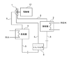
図1は、本発明に係るターボ冷凍機を示す模式図である。図1に示すように、ターボ冷凍機は、冷媒を圧縮するターボ圧縮機1と、圧縮された冷媒ガスを冷却水(冷却流体)で冷却して凝縮させる凝縮器2と、冷水(被冷却流体)から熱を奪って冷媒が蒸発し冷凍効果を発揮する蒸発器3と、凝縮器2と蒸発器3との間に配置される中間冷却器であるエコノマイザ4とを備え、これら各機器を冷媒が循環する冷媒配管5によって連結して構成されている。
Hereinafter, an embodiment of a turbo refrigerator according to the present invention will be described with reference to FIGS. 1 to 4. 1 to 4, the same or corresponding components are denoted by the same reference numerals, and redundant description is omitted.
FIG. 1 is a schematic view showing a turbo refrigerator according to the present invention. As shown in FIG. 1, a turbo refrigerator includes a
図1に示す実施形態においては、ターボ圧縮機1は、多段ターボ圧縮機から構成されている。ターボ圧縮機1は、冷媒配管5によってエコノマイザ4と接続されており、エコノマイザ4で分離された冷媒ガスは多段ターボ圧縮機の多段の圧縮段(この例では2段)の中間部分(この例では一段目と二段目の間の部分)に導入されるようになっている。
In the embodiment shown in FIG. 1, the
図1に示すように構成されたターボ冷凍機の冷凍サイクルでは、ターボ圧縮機1と凝縮器2と蒸発器3とエコノマイザ4とを冷媒が循環し、蒸発器3で冷水が製造されて負荷に対応し、冷凍サイクル内に取り込まれた蒸発器3からの熱量および圧縮機モータから供給されるターボ圧縮機1の仕事に相当する熱量が凝縮器2に供給される冷却水に放出される。一方、エコノマイザ4にて分離されたガス冷媒はターボ圧縮機1の多段圧縮段の中間部分に導入され、一段目圧縮機からのガス冷媒と合流して二段目圧縮機により圧縮される。2段圧縮単段エコノマイザサイクルによれば、エコノマイザ4による冷凍効果部分が付加されるので、その分だけ冷凍効果が増加し、エコノマイザ4を設置しない場合に比べて冷凍効果の高効率化を図ることができる。
In the refrigeration cycle of the turbo chiller configured as shown in FIG. 1, the refrigerant circulates through the
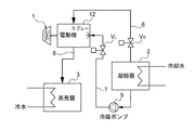
図2は、図1に示すターボ冷凍機におけるターボ圧縮機1の電動機12に冷却用冷媒を供給する構成を示す模式図である。図2に示すように、ターボ冷凍機は、凝縮器2から電動機12にガス冷媒を供給するガス冷媒供給配管6と、凝縮器2から電動機12に液冷媒を供給する液冷媒供給配管7と、電動機12を冷却した後の冷媒を蒸発器3に戻す冷却冷媒戻り配管8とを備えている。ガス冷媒供給配管6には、ガス冷媒制御弁VGが設置され、液冷媒供給配管7には、冷媒ポンプ9と液冷媒制御弁VLとが設置されている。
FIG. 2 is a schematic diagram showing a configuration for supplying a cooling refrigerant to the
次に、図2に示す構成を備えたターボ冷凍機においてターボ圧縮機1の電動機12の冷却方法について説明する。
1)液冷媒とガス冷媒の併用による冷却
i)本発明はエコノマイザを持つターボ冷凍機を対象とするが、エコノマイザが無くてもよい。ターボ冷凍機の電動機は液冷媒によって冷却することが一般的である。液冷媒は電動機の熱で蒸発し、おもにその潜熱で電動機を冷却する。
液冷媒は凝縮器2から冷媒ポンプ9によって電動機12に供給する。圧力関係は、蒸発器≦電動機≦凝縮器 となるため、冷媒ポンプは無くても良い。蒸発したガスは圧力の低い蒸発器3に向けて排出する。凝縮器2やエコノマイザ4(図1参照)に排出することもできる。
ii)液冷媒を電動機内部に均一に行き渡らせ、すべて蒸発させることは技術的に困難である。実際には必要量の数倍の液冷媒を電動機12の中に散布している。未蒸発の液冷媒は電動機12の下部から蒸発器3に向けて排出される。この液冷媒はエコノマイザを経由しないので損失となり、冷凍機の効率を低下させる。
iii)一方、ガス冷媒で電動機12を冷却する場合は液冷媒の排出はない。ガス冷媒は比熱が小さいため、電動機の発熱量をすべて冷却するには多大な流量を必要とする。大量のガスを供給するための大口径のガス流路が必要になる。電動機内の温度分布は均一ではなく、コイルなど電流が流れる部分が発熱して高温になる。
iv)そこで本発明では、電動機の高温部に向けて液冷媒を散布して効果的に冷却を行う。また、ガス冷媒の流入路も設けることで全体をガス冷媒で冷却する。これにより、電動機12の冷却効果を落とすことなく、液冷媒の散布量を減らすことができる。液冷媒の排出量が減少し、冷凍機の効率が向上する。
2)電動機の負荷が小さいときには、ガス冷媒のみによる冷却
i)冷凍機の負荷と電動機の発熱量とは相関する。冷凍機の負荷が高い時は発熱量が多い。負荷が低い時は発熱量が小さい。年間を通してみると、冷凍機は低い負荷で運転される時間が圧倒的に長い。低負荷時は電動機の発熱量が少ないので液冷媒の散布量を減らしても冷却ができる。さらに条件によっては、液冷媒の散布を止めてガス冷媒だけでも冷却ができる。
ii)そこで本発明では、液冷媒供給配管7に液冷媒制御弁VLを設け、負荷に応じて液冷媒の散布量を制御する。液冷媒制御弁VLはON/OFF式でも良いし、開度を連続的に制御できるものでも良い。
ターボ冷凍機の負荷が所定の値よりも小さいときには、液冷媒制御弁VLを閉じ、電動機12をガス冷媒のみで冷却する。ここで、所定の値とは、モータのコイル温度が例えば80℃を超えることがないような負荷で、実験的に求めるとよい。
負荷の検出は、例えば電動機に設けた温度センサの値をもとにする。他に、電流値やベーン開度、冷水温度差など、負荷状態に相関する物理量でも良い。これにより、電動機の冷却効果を落とすことなく、液冷媒の散布量を減らすことができる。液冷媒の排出量が減少し、冷凍機の効率が向上する。
3)ガス冷媒の流量調整
i)上記2)と同様に、ガス冷媒供給配管6にも制御弁VGを設け、負荷に応じてガス冷媒の流量を制御する。冷却用のガス冷媒を減らすことで、圧縮機の仕事が減少し、結果として冷凍機の効率が向上する。
ターボ冷凍機の負荷が所定の値よりも大きいときには、ガス冷媒流量が100%になるようにガス冷媒制御弁VGを制御し、さらに、前記液冷媒制御弁VLを前記負荷に応じて制御する。ここで、所定の値とは、モータのコイル温度が例えば80℃を超えることがないような負荷で、実験的に求めるとよい。
ii)また、冷凍機の負荷が小さい時はホットガスバイパスが広く実施されている。これは凝縮器の冷媒ガスを蒸発器に流入させて冷凍機の低負荷絞りに対応するものである。通常はホットガスバイパス用の配管と制御弁を設ける必要がある。
図2に示すように、ガス冷媒供給配管6に制御弁VGを設けることで、これをホットガスバイパスと兼用することができる。極低負荷時に制御弁VGを開く制御を行うことで、冷凍機を低負荷まで絞ることができる。
Next, a method for cooling the
1) Cooling by combined use of liquid refrigerant and gas refrigerant i) Although the present invention is directed to a turbo refrigerator having an economizer, the economizer may be omitted. Generally, an electric motor of a turbo refrigerator is cooled by a liquid refrigerant. The liquid refrigerant evaporates with the heat of the electric motor, and mainly cools the electric motor with its latent heat.
The liquid refrigerant is supplied from the condenser 2 to the
ii) It is technically difficult to distribute the liquid refrigerant uniformly inside the motor and evaporate all of it. Actually, several times the required amount of liquid refrigerant is dispersed in the
iii) On the other hand, when the
iv) Therefore, in the present invention, the liquid refrigerant is sprayed toward the high temperature portion of the electric motor to effectively perform cooling. Moreover, the whole is cooled with a gas refrigerant by providing an inflow passage for the gas refrigerant. Thereby, the spraying amount of the liquid refrigerant can be reduced without reducing the cooling effect of the
2) When the load on the motor is small, cooling with only the gas refrigerant i) The load on the refrigerator and the amount of heat generated by the motor are correlated. When the load on the refrigerator is high, it generates a lot of heat. When the load is low, the calorific value is small. Throughout the year, refrigerators are overwhelmingly long operating at low loads. When the load is low, the amount of heat generated by the motor is small, so cooling can be achieved even if the amount of liquid refrigerant sprayed is reduced. Furthermore, depending on the conditions, it is possible to cool the liquid refrigerant alone by stopping the spraying of the liquid refrigerant.
ii) Therefore, in the present invention, the liquid refrigerant supply pipe 7 is provided with a liquid refrigerant control valve V L to control the amount of liquid refrigerant sprayed according to the load. The liquid refrigerant control valve VL may be an ON / OFF type or a valve capable of continuously controlling the opening degree.
When the load of the turbo refrigerator is smaller than a predetermined value, the liquid refrigerant control valve VL is closed and the
For example, the load is detected based on the value of a temperature sensor provided in the electric motor. In addition, a physical quantity correlated with a load state such as a current value, a vane opening degree, or a cold water temperature difference may be used. Thereby, the spraying amount of the liquid refrigerant can be reduced without reducing the cooling effect of the electric motor. The amount of liquid refrigerant discharged is reduced and the efficiency of the refrigerator is improved.
3) Like the flow rate adjusting i) above 2) of gas refrigerant, the control valve V G provided in the gas
When the load of the turbo chiller is greater than a predetermined value, it controls the gas refrigerant control valve V G so that the gas refrigerant flow rate is 100%, further controlled in accordance with the liquid refrigerant control valve V L to the load To do. Here, the predetermined value may be experimentally obtained with a load such that the coil temperature of the motor does not exceed 80 ° C., for example.
ii) Hot gas bypass is widely implemented when the load on the refrigerator is small. This corresponds to the low load throttling of the refrigerator by allowing the refrigerant gas of the condenser to flow into the evaporator. Normally, it is necessary to provide piping and a control valve for hot gas bypass.
As shown in FIG. 2, by providing the control valve V G to the gas
図3は、図1に示すターボ冷凍機の負荷を判定する構成を示す模式図である。
1)冷水の温度による判定
図3に示すように、蒸発器3には、冷水入口温度を測定する温度センサT1と、冷水出口温度を測定する温度センサT2とが設置されている。すなわち、温度センサT1により蒸発器3内の冷媒と熱交換する冷水の入口温度を測定し、温度センサT2により蒸発器3内の冷媒と熱交換した後の冷水の出口温度を測定するようになっている。温度センサT1および温度センサT2は、それぞれ制御装置10に接続されている。これにより、制御装置10において、冷水入口温度と冷水出口温度との温度差と、定格(固定)の冷水流量とから冷凍能力Qeを算出することができるようになっている。蒸発器3を流れる冷水流量が変流量である場合には、図3に示すように、冷水出口配管に冷水流量を計測する流量センサFEを設けることにより、冷水入口温度と冷水出口温度との温度差と、流量センサFEで計測した冷水流量とを乗算することにより冷凍能力Qeを算出することができる。
FIG. 3 is a schematic diagram showing a configuration for determining the load of the turbo refrigerator shown in FIG.
1) Judgment by Temperature of Cold Water As shown in FIG. 3, the
なお、図3に示すように、冷水入口配管と冷水出口配管との間に差圧計ΔPeを設けて蒸発器3で生ずる冷水圧力損失を計測し、蒸発器3の冷水圧力損失から蒸発器3を流れる冷水流量を推算し、推算した冷水流量に、冷水入口温度と冷水出口温度との温度差を乗算することにより冷凍能力Qeを算出してもよい。
このように、制御装置10は、冷凍能力Qeを算出することにより、ターボ冷凍機が低負荷であるか高負荷であるかを判断し、高負荷の場合にはガス冷媒と液冷媒とを併用して電動機12を冷却し、低負荷の場合には電動機12をガス冷媒と少量の液冷媒で、またはガス冷媒のみで冷却する。
As shown in FIG. 3, a differential pressure gauge ΔPe is provided between the cold water inlet pipe and the cold water outlet pipe to measure the cold water pressure loss generated in the
In this way, the
2)電動機内部の温度による判定
図3に示すように、電動機12には、電動機内部の温度を測定する温度センサT3が設置されている。温度センサT3は、例えば、熱電対を用い、温度センサの検出端は電動機内部で最も高温になる部分の温度が測定できるようになっている。温度センサT3は、制御装置10に接続されている。ターボ冷凍機の稼働中に温度センサT3により電動機12の内部の温度を測定する。制御装置10は、温度センサT3の測定信号に基づいてターボ冷凍機が低負荷であるか高負荷であるかを判断し、高負荷の場合にはガス冷媒と液冷媒とを併用して電動機12を冷却し、低負荷の場合には電動機12をガス冷媒と少量の液冷媒で、またはガス冷媒のみで冷却する。
2) Determination based on the temperature inside the motor As shown in FIG. 3, the
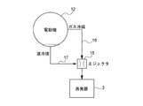
図4は、電動機12を冷却した後の冷媒を蒸発器3に戻すための構成を示す模式図である。
図2に示す電動機を冷却する構成において、液冷媒を用いて電動機12を冷却した場合、液冷媒の多くは蒸発してガスになるが、蒸発しきれないで残った液冷媒は電動機12の底部に溜まる。そこで、本発明においては、図4に示すように、電動機12から排出されるガス冷媒を駆動用ガスとして、電動機12に溜まっている液冷媒を吸引して該液冷媒を電動機12から排出するためのエジェクタ15を設けている。ガス冷媒を電動機12からエジェクタ15に導くガス冷媒排出配管16は、電動機12の上部側に接続されている。液冷媒を電動機12から吸引するための液冷媒排出配管17は、電動機12の底部側に接続されている。エジェクタ15の吐出側は蒸発器3に接続されている。
FIG. 4 is a schematic diagram showing a configuration for returning the refrigerant after cooling the
In the configuration for cooling the electric motor shown in FIG. 2, when the
図4に示す構成において、電動機12から排出されるガス冷媒はガス冷媒排出配管16を介してエジェクタ15に供給される。エジェクタ15に供給されるガス冷媒は、所定の圧力を持っているため、エジェクタ15を駆動する駆動用ガスとして機能し、エジェクタ15内に負圧が形成される。そのため、電動機12に溜まっている液冷媒は、エジェクタ15に吸引されるため電動機12から排出される。エジェクタ15で合流したガス冷媒と液冷媒は、エジェクタ15の吐出側から1本の配管で蒸発器3に戻すことができる。
In the configuration shown in FIG. 4, the gas refrigerant discharged from the
これまで本発明の実施形態について説明したが、本発明は上述の実施形態に限定されず、その技術思想の範囲内において、種々の異なる形態で実施されてよいことは勿論である。 Although the embodiment of the present invention has been described so far, the present invention is not limited to the above-described embodiment, and it is needless to say that the present invention may be implemented in various different forms within the scope of the technical idea.
1 ターボ圧縮機
2 凝縮器
3 蒸発器
4 エコノマイザ
5 冷媒配管
6 ガス冷媒供給配管
7 液冷媒供給配管
8 冷却冷媒戻り配管
9 冷媒ポンプ
10 制御装置
12 電動機
15 エジェクタ
16 ガス冷媒排出配管
17 液冷媒排出配管
T1,T2,T3 温度センサ
FE 流量センサ
DESCRIPTION OF
Claims (6)
前記凝縮器から前記電動機にガス冷媒を供給するガス冷媒供給配管と、
前記凝縮器から前記電動機に液冷媒を供給する液冷媒供給配管とを備え、
前記電動機をガス冷媒と液冷媒とを併用して冷却するようにしたことを特徴とするターボ冷凍機。 An evaporator that draws heat from cold water and evaporates the refrigerant to exert a refrigeration effect, a turbo compressor that compresses the refrigerant with an impeller, an electric motor that drives the turbo compressor, and the compressed refrigerant is cooled with cooling water In a centrifugal chiller equipped with a condenser for condensing
A gas refrigerant supply pipe for supplying a gas refrigerant from the condenser to the electric motor;
A liquid refrigerant supply pipe for supplying liquid refrigerant from the condenser to the electric motor,
A turbo refrigerator, wherein the electric motor is cooled by using a gas refrigerant and a liquid refrigerant in combination.
ターボ冷凍機の負荷が所定の値よりも小さいときには、前記液冷媒制御弁を閉じ、前記電動機をガス冷媒のみで冷却するようにしたことを特徴とする請求項1記載のターボ冷凍機。 A liquid refrigerant control valve installed in the liquid refrigerant supply pipe, and means for detecting a refrigeration load,
2. The turbo chiller according to claim 1, wherein when the load of the turbo chiller is smaller than a predetermined value, the liquid refrigerant control valve is closed and the electric motor is cooled only by a gas refrigerant.
Priority Applications (1)
| Application Number | Priority Date | Filing Date | Title |
|---|---|---|---|
| JP2016092281A JP6630627B2 (en) | 2016-05-02 | 2016-05-02 | Turbo refrigerator |
Applications Claiming Priority (1)
| Application Number | Priority Date | Filing Date | Title |
|---|---|---|---|
| JP2016092281A JP6630627B2 (en) | 2016-05-02 | 2016-05-02 | Turbo refrigerator |
Publications (2)
| Publication Number | Publication Date |
|---|---|
| JP2017201216A true JP2017201216A (en) | 2017-11-09 |
| JP6630627B2 JP6630627B2 (en) | 2020-01-15 |
Family
ID=60264691
Family Applications (1)
| Application Number | Title | Priority Date | Filing Date |
|---|---|---|---|
| JP2016092281A Active JP6630627B2 (en) | 2016-05-02 | 2016-05-02 | Turbo refrigerator |
Country Status (1)
| Country | Link |
|---|---|
| JP (1) | JP6630627B2 (en) |
Cited By (1)
| Publication number | Priority date | Publication date | Assignee | Title |
|---|---|---|---|---|
| CN110411045A (en) * | 2019-07-31 | 2019-11-05 | 珠海格力电器股份有限公司 | Centrifugal unit and air conditioning system |
Citations (16)
| Publication number | Priority date | Publication date | Assignee | Title |
|---|---|---|---|---|
| JPS4111419Y1 (en) * | 1963-12-27 | 1966-05-27 | ||
| JPS5283054U (en) * | 1975-12-19 | 1977-06-21 | ||
| JPS6071859A (en) * | 1983-09-28 | 1985-04-23 | 株式会社荏原製作所 | Heat pump |
| JPS62171860U (en) * | 1986-02-28 | 1987-10-31 | ||
| JPH03213959A (en) * | 1990-01-18 | 1991-09-19 | Ebara Corp | Oil recovery device in closed type turbo freezer |
| JPH10238869A (en) * | 1997-02-21 | 1998-09-08 | Kobe Steel Ltd | Refrigerating plant |
| JP2005312272A (en) * | 2004-04-26 | 2005-11-04 | Mitsubishi Heavy Ind Ltd | Turbo refrigerator and motor for the turbo refrigerator |
| JP2009300008A (en) * | 2008-06-13 | 2009-12-24 | Mitsubishi Heavy Ind Ltd | Refrigerator |
| JP2014066472A (en) * | 2012-09-27 | 2014-04-17 | Fujitsu General Ltd | Air conditioning apparatus and compressor used for the same |
| JP2014159923A (en) * | 2013-02-20 | 2014-09-04 | Ebara Refrigeration Equipment & Systems Co Ltd | Turbo refrigerator |
| JP2014163625A (en) * | 2013-02-27 | 2014-09-08 | Ebara Refrigeration Equipment & Systems Co Ltd | Turbo refrigerator |
| JP2014163624A (en) * | 2013-02-27 | 2014-09-08 | Ebara Refrigeration Equipment & Systems Co Ltd | Turbo refrigerator |
| JP2015045335A (en) * | 2008-03-13 | 2015-03-12 | エーエーエフ−マックウェイ インク. | High capacity chiller system operating method and compressor assembly |
| JP2015183979A (en) * | 2014-03-26 | 2015-10-22 | 荏原冷熱システム株式会社 | turbo refrigerator |
| JP2015194300A (en) * | 2014-03-31 | 2015-11-05 | 荏原冷熱システム株式会社 | turbo refrigerator |
| US20160054040A1 (en) * | 2013-05-02 | 2016-02-25 | Carrier Corporation | Compressor Bearing Cooling Via Purge Unit |
-
2016
- 2016-05-02 JP JP2016092281A patent/JP6630627B2/en active Active
Patent Citations (16)
| Publication number | Priority date | Publication date | Assignee | Title |
|---|---|---|---|---|
| JPS4111419Y1 (en) * | 1963-12-27 | 1966-05-27 | ||
| JPS5283054U (en) * | 1975-12-19 | 1977-06-21 | ||
| JPS6071859A (en) * | 1983-09-28 | 1985-04-23 | 株式会社荏原製作所 | Heat pump |
| JPS62171860U (en) * | 1986-02-28 | 1987-10-31 | ||
| JPH03213959A (en) * | 1990-01-18 | 1991-09-19 | Ebara Corp | Oil recovery device in closed type turbo freezer |
| JPH10238869A (en) * | 1997-02-21 | 1998-09-08 | Kobe Steel Ltd | Refrigerating plant |
| JP2005312272A (en) * | 2004-04-26 | 2005-11-04 | Mitsubishi Heavy Ind Ltd | Turbo refrigerator and motor for the turbo refrigerator |
| JP2015045335A (en) * | 2008-03-13 | 2015-03-12 | エーエーエフ−マックウェイ インク. | High capacity chiller system operating method and compressor assembly |
| JP2009300008A (en) * | 2008-06-13 | 2009-12-24 | Mitsubishi Heavy Ind Ltd | Refrigerator |
| JP2014066472A (en) * | 2012-09-27 | 2014-04-17 | Fujitsu General Ltd | Air conditioning apparatus and compressor used for the same |
| JP2014159923A (en) * | 2013-02-20 | 2014-09-04 | Ebara Refrigeration Equipment & Systems Co Ltd | Turbo refrigerator |
| JP2014163625A (en) * | 2013-02-27 | 2014-09-08 | Ebara Refrigeration Equipment & Systems Co Ltd | Turbo refrigerator |
| JP2014163624A (en) * | 2013-02-27 | 2014-09-08 | Ebara Refrigeration Equipment & Systems Co Ltd | Turbo refrigerator |
| US20160054040A1 (en) * | 2013-05-02 | 2016-02-25 | Carrier Corporation | Compressor Bearing Cooling Via Purge Unit |
| JP2015183979A (en) * | 2014-03-26 | 2015-10-22 | 荏原冷熱システム株式会社 | turbo refrigerator |
| JP2015194300A (en) * | 2014-03-31 | 2015-11-05 | 荏原冷熱システム株式会社 | turbo refrigerator |
Cited By (1)
| Publication number | Priority date | Publication date | Assignee | Title |
|---|---|---|---|---|
| CN110411045A (en) * | 2019-07-31 | 2019-11-05 | 珠海格力电器股份有限公司 | Centrifugal unit and air conditioning system |
Also Published As
| Publication number | Publication date |
|---|---|
| JP6630627B2 (en) | 2020-01-15 |
Similar Documents
| Publication | Publication Date | Title |
|---|---|---|
| JP6682301B2 (en) | Vapor compression refrigerator and control method thereof | |
| JP5981180B2 (en) | Turbo refrigerator and control method thereof | |
| JP2014159923A (en) | Turbo refrigerator | |
| JP6087744B2 (en) | refrigerator | |
| JP6340213B2 (en) | Turbo refrigerator | |
| CN103443563A (en) | Expansion valve control device, heat source machine, and expansion valve control method | |
| CN109682106B (en) | Refrigerant circulation system for slowing down surge of compressor, control method thereof and air conditioner | |
| CN107588573B (en) | Air conditioner, compressor protection method, computer device, and readable storage medium | |
| CN103307795A (en) | Turborefrigerator and method thereof | |
| JP5412193B2 (en) | Turbo refrigerator | |
| JP2012242053A (en) | Refrigeration air conditioning system | |
| JP2010002173A (en) | Refrigerator | |
| WO2020070793A1 (en) | Refrigeration cycle apparatus | |
| JP2014190614A (en) | Turbo refrigerator | |
| JP2014163624A (en) | Turbo refrigerator | |
| JP6097109B2 (en) | Turbo refrigerator | |
| JP2009186033A (en) | Two-stage compression refrigeration system | |
| JP2014085048A (en) | Turbo refrigerator | |
| JP2014190579A5 (en) | ||
| JP6630627B2 (en) | Turbo refrigerator | |
| JP6069179B2 (en) | Turbo refrigerator | |
| JP6140065B2 (en) | Turbo refrigerator | |
| JP2015194301A (en) | turbo refrigerator | |
| JP2013170747A (en) | Refrigerant leakage detection device and freezing device | |
| JP6096551B2 (en) | Turbo refrigerator |
Legal Events
| Date | Code | Title | Description |
|---|---|---|---|
| A621 | Written request for application examination |
Free format text: JAPANESE INTERMEDIATE CODE: A621 Effective date: 20180920 |
|
| A977 | Report on retrieval |
Free format text: JAPANESE INTERMEDIATE CODE: A971007 Effective date: 20190717 |
|
| A131 | Notification of reasons for refusal |
Free format text: JAPANESE INTERMEDIATE CODE: A131 Effective date: 20190723 |
|
| A521 | Request for written amendment filed |
Free format text: JAPANESE INTERMEDIATE CODE: A523 Effective date: 20190917 |
|
| TRDD | Decision of grant or rejection written | ||
| A01 | Written decision to grant a patent or to grant a registration (utility model) |
Free format text: JAPANESE INTERMEDIATE CODE: A01 Effective date: 20191203 |
|
| A61 | First payment of annual fees (during grant procedure) |
Free format text: JAPANESE INTERMEDIATE CODE: A61 Effective date: 20191209 |
|
| R150 | Certificate of patent or registration of utility model |
Ref document number: 6630627 Country of ref document: JP Free format text: JAPANESE INTERMEDIATE CODE: R150 |
|
| S531 | Written request for registration of change of domicile |
Free format text: JAPANESE INTERMEDIATE CODE: R313531 |
|
| R350 | Written notification of registration of transfer |
Free format text: JAPANESE INTERMEDIATE CODE: R350 |
|
| R250 | Receipt of annual fees |
Free format text: JAPANESE INTERMEDIATE CODE: R250 |
|
| R250 | Receipt of annual fees |
Free format text: JAPANESE INTERMEDIATE CODE: R250 |
|
| R250 | Receipt of annual fees |
Free format text: JAPANESE INTERMEDIATE CODE: R250 |
|
| R250 | Receipt of annual fees |
Free format text: JAPANESE INTERMEDIATE CODE: R250 |