JP2017201219A - Drying device, light irradiation device, and coating system - Google Patents
Drying device, light irradiation device, and coating system Download PDFInfo
- Publication number
- JP2017201219A JP2017201219A JP2016092474A JP2016092474A JP2017201219A JP 2017201219 A JP2017201219 A JP 2017201219A JP 2016092474 A JP2016092474 A JP 2016092474A JP 2016092474 A JP2016092474 A JP 2016092474A JP 2017201219 A JP2017201219 A JP 2017201219A
- Authority
- JP
- Japan
- Prior art keywords
- substrate
- loading
- unloading
- drying
- fork
- Prior art date
- Legal status (The legal status is an assumption and is not a legal conclusion. Google has not performed a legal analysis and makes no representation as to the accuracy of the status listed.)
- Granted
Links
Images


Landscapes
- Drying Of Solid Materials (AREA)
Abstract
【課題】基板の端面や周縁部に液剤が塗布された基板を複数枚まとめて効率良く、きれいに乾燥処理することができ、しかも小型化を図ることができる乾燥装置を提供すること。【解決手段】基板2を乾燥させる乾燥室31と、乾燥室31に基板2を搬入する搬入装置81と、乾燥室31から基板2を搬出する搬出装置91とを備えた乾燥装置30であって、乾燥室31が、基板2が載置される複数段の棚部32と、各棚部32に重ねて配置される基板押え部材41と、各棚部32に対応して設けられた搬入用開閉扉51と、各棚部32に対応して設けられた搬出用開閉扉52と、複数段の棚部32に載置される基板2の各辺に沿った一定方向に風を送り出す送風部62と、乾燥室31内の気体を吸引する吸引部62とを備え、搬入装置81が、棚部32と基板押え部材41との間に基板2を搬入し、搬出装置91が、棚部32と基板押え部材41との間から基板2を搬出する。【選択図】図2To provide a drying device capable of efficiently and cleanly drying a plurality of substrates having liquid agent applied to their end faces and peripheral portions together, and capable of miniaturization. A drying apparatus (30) comprising a drying chamber (31) for drying a substrate (2), a loading device (81) for loading the substrate (2) into the drying chamber (31), and a carrying-out device (91) for carrying the substrate (2) out of the drying chamber (31). , the drying chamber 31 is composed of a plurality of shelves 32 on which the substrates 2 are placed, substrate holding members 41 arranged to overlap each shelf 32 , and carrying-in trays provided corresponding to each shelf 32 . An opening/closing door 51, an unloading opening/closing door 52 provided corresponding to each shelf portion 32, and a blowing portion that blows air in a fixed direction along each side of the substrate 2 placed on the plurality of shelves 32. 62 and a suction unit 62 for sucking gas in the drying chamber 31 . and the substrate pressing member 41. [Selection drawing] Fig. 2
Description
本発明は乾燥装置、光照射装置、及び塗布システムに関し、より詳細には、基板の端面や該端面を含む周縁部に塗布された液剤を乾燥させることができる乾燥装置、前記液剤を光化学反応により硬化・乾燥させることができる光照射装置、前記乾燥装置及び/又は前記光照射装置を含んで構成される塗布システムに関する。 The present invention relates to a drying device, a light irradiation device, and a coating system, and more specifically, a drying device capable of drying a liquid agent applied to an edge surface of a substrate or a peripheral portion including the end surface, and the liquid agent by photochemical reaction. The present invention relates to a light irradiation apparatus that can be cured and dried, the drying apparatus, and / or a coating system that includes the light irradiation apparatus.
電子部品の実装用基板としてガラスエポキシ部材を使用したプリント基板が一般的に使用されている。ガラスエポキシ部材は、ガラス繊維布を重ねたものにエポキシ樹脂を含浸させたものである。そのためガラスエポキシ部材を切断すると、エポキシ樹脂又はガラス繊維からなる細かい塵埃が発生する。このような細かい塵埃は基板回路の接触不良や品位の低下などを引き起こすおそれがある。そのため、基板の切断時に生じた塵埃はプリント基板の製造時に除去しておく必要がある。
しかし、プリント基板の端面から塵埃を取り除いたとしても、プリント基板の端面部分は脆いため、崩壊して更なる塵埃が発生するおそれがあるという課題があった。
A printed circuit board using a glass epoxy member is generally used as a substrate for mounting electronic components. The glass epoxy member is obtained by impregnating a glass fiber cloth with an epoxy resin. Therefore, when the glass epoxy member is cut, fine dust made of epoxy resin or glass fiber is generated. Such fine dust may cause poor contact of the circuit board and deterioration of the quality. Therefore, it is necessary to remove dust generated when the substrate is cut when the printed circuit board is manufactured.
However, even if dust is removed from the end face of the printed circuit board, the end face portion of the printed circuit board is fragile, and there is a problem that it may collapse and generate further dust.
そこで本発明者は先に、プリント基板や銅張積層基板(パッケージ基板ともいう)等の基板の端面や該端面を含む周縁部に液体(膜形成液)を塗布して塗膜を形成し、後の生産工程での基板端面部分の崩壊や該崩壊による塵埃の発生を防止することのできる塗布ユニットを含む塗布システムを提案した(特許文献1、2)。
上記特許文献1、2で提案された塗布システムによれば、前記塗布ユニットにおいて、基板の端面を含む周縁部に膜形成液を薄く且つ均一な膜厚で効率良く塗布することが可能となった。また、前記塗布ユニットを通過した基板は、その後、乾燥装置(乾燥炉)に搬送され、該乾燥装置で、基板の周縁部に形成された塗膜が乾燥されるようになっている。
Therefore, the present inventor first forms a coating film by applying a liquid (film forming liquid) to an edge surface of a substrate such as a printed circuit board or a copper clad laminated substrate (also referred to as a package substrate) or a peripheral portion including the end surface, A coating system including a coating unit capable of preventing the collapse of the end face portion of the substrate and the generation of dust due to the collapse in the subsequent production process has been proposed (Patent Documents 1 and 2).
According to the coating system proposed in
[発明が解決しようとする課題]
上記乾燥装置が、基板を1枚ずつ乾燥処理する方式となっている場合、塗膜の乾燥時間が短い場合は比較的効率良く乾燥処理を行うことができる一方、乾燥しにくい液剤を使用した場合、塗膜の乾燥時間が長くなるため乾燥処理を効率良く行うことが難しく、前記塗布ユニットの上記効果を十分に発揮させることができないという課題があった。
また、前記乾燥装置をコンベア方式にすることは可能であるが、乾燥室が大型となるため設置スペースが多く必要となり、またコンベアでの基板搬送時に、基板の周縁部に形成された未乾燥の塗膜が剥がれるおそれがあるという課題があった。
[Problems to be solved by the invention]
When the above drying device is a method of drying the substrates one by one, when the drying time of the coating film is short, the drying process can be performed relatively efficiently, while the liquid agent that is difficult to dry is used Since the drying time of the coating film becomes long, it is difficult to efficiently perform the drying process, and there is a problem that the above-described effect of the coating unit cannot be sufficiently exhibited.
In addition, although it is possible to use a conveyor system for the drying apparatus, a large drying space is required, so a large installation space is required, and when the substrate is transported by the conveyor, the drying apparatus is formed on the periphery of the substrate. There existed a subject that a coating film might peel.
また、基板の端面や周縁部に塗布する液剤に紫外線硬化性材料が含まれる場合、前記乾燥装置による乾燥処理の他に、前記液剤を硬化させるために紫外線照射装置を使用する方法が考えられる。しかしながら、一般的なランプ方式の紫外線照射装置では、基板の端面や周縁部のみに適切に紫外線を照射することが難しく、基板の端面や周縁部にのみ紫外線を適切に照射することができる装置についてはこれまで提案されていなかった。 In addition, when an ultraviolet curable material is included in the liquid agent applied to the end face or the peripheral edge of the substrate, a method of using an ultraviolet irradiation device to cure the liquid agent can be considered in addition to the drying treatment by the drying device. However, in a general lamp-type ultraviolet irradiation device, it is difficult to appropriately irradiate only the end surface and the peripheral portion of the substrate with ultraviolet rays, and the device that can appropriately irradiate only the end surface and the peripheral portion of the substrate with ultraviolet light. Has never been proposed before.
本発明は上記課題に鑑みなされたものであって、基板の端面や周縁部に液剤が塗布された基板を複数枚まとめて効率良く、きれいに乾燥処理することができ、しかも小型化を図ることができる乾燥装置、基板の端面や周縁部に、液剤を硬化・乾燥させるための光を適切に照射することができる光照射装置、及びこれら乾燥装置及び/又は光照射装置を備えた塗布システムを提供することを目的としている。 The present invention has been made in view of the above problems, and a plurality of substrates coated with a liquid agent on the end surface or peripheral edge of the substrate can be efficiently and neatly dried together, and the size can be reduced. Provided is a drying device capable of appropriately irradiating the end face and peripheral edge of the substrate with light for curing and drying the liquid agent, and a coating system including these drying device and / or light irradiation device. The purpose is to do.
上記目的を達成するために本発明に係る乾燥装置(1)は、基板を乾燥させる乾燥室と、該乾燥室に基板を搬入する搬入手段と、前記乾燥室から基板を搬出する搬出手段とを備えた乾燥装置であって、前記乾燥室が、基板が載置される複数段の棚部と、これら各棚部に重ねて配置される基板押え手段と、前記各棚部に対応して設けられた搬入用開閉扉と、前記各棚部に対応して設けられた搬出用開閉扉と、前記複数段の棚部に載置される基板の各辺に沿った一定方向に風を送り出す送風手段と、前記乾燥室内の気体を吸引する吸引手段とを備え、前記搬入手段が、前記棚部と前記基板押え手段との間に基板を搬入するように構成され、前記搬出手段が、前記棚部と前記基板押え手段との間から基板を搬出するように構成されていることを特徴としている。 In order to achieve the above object, a drying apparatus (1) according to the present invention includes a drying chamber for drying a substrate, loading means for loading the substrate into the drying chamber, and unloading means for unloading the substrate from the drying chamber. The drying chamber is provided with a plurality of shelves on which the substrate is placed, a substrate pressing unit disposed on each of the shelves, and a corresponding one of the shelves. The opening / closing door for loading, the opening / closing door provided corresponding to each of the shelves, and the air blowing that sends wind in a fixed direction along each side of the substrate placed on the plurality of shelves And a suction means for sucking the gas in the drying chamber, the carry-in means is configured to carry a substrate between the shelf portion and the substrate holding means, and the carry-out means is the shelf. Characterized in that the substrate is carried out from between the portion and the substrate pressing means. It is.
上記乾燥装置(1)によれば、前記乾燥室の各棚部に一枚ずつ基板を搬入出することができるとともに、前記乾燥室に複数の基板を収容することができ、装置の省スペース化、小型化を図ることができる。また、乾燥中は、前記基板押え手段で基板が押えられるため、送風による基板の浮き上りや位置ずれを防止することができ、また、前記送風手段により、基板の各辺(端面や周縁部)に効率良く風を吹き付けることができ、基板の端面や周縁部に塗布された液剤を効率よく、しかもきれいに乾燥させることができる。 According to the said drying apparatus (1), while being able to carry in and out a board | substrate one by one in each shelf part of the said drying chamber, a several board | substrate can be accommodated in the said drying chamber, and space saving of an apparatus is possible. Therefore, the size can be reduced. In addition, since the substrate is pressed by the substrate pressing means during drying, it is possible to prevent the substrate from being lifted or displaced due to the air blowing, and each side (end surface or peripheral edge portion) of the substrate by the air blowing means. The air can be efficiently blown on the substrate, and the liquid applied to the end face and the peripheral edge of the substrate can be efficiently and neatly dried.
また本発明に係る乾燥装置(2)は、上記乾燥装置(1)において、前記棚部が、前記搬入用開閉扉側に設けられた搬入側下枠部と、前記搬出用開閉扉側に設けられた搬出側下枠部と、前記搬入側下枠部と前記搬出側下枠部との間に架設された複数の桟部材とを含み、前記搬入手段が、基板が載置される搬入用フォーク部と、該搬入用フォーク部を昇降させる昇降手段と、前記搬入用フォーク部を水平方向に移動させる水平移動手段とを備え、前記搬出手段が、基板が載置される搬出用フォーク部と、該搬出用フォーク部を昇降させる昇降手段と、前記搬出用フォーク部を水平方向に移動させる水平移動手段とを備え、前記搬入用フォーク部と前記搬出用フォーク部とが、前記複数の桟部材の間を昇降可能に構成されていることを特徴としている。 In the drying device (2) according to the present invention, in the drying device (1), the shelf portion is provided on the loading-side lower frame portion provided on the loading door and the unloading door side. An unloading-side lower frame portion, and a plurality of cross members laid between the unloading-side lower frame portion and the unloading-side lower frame portion, and the loading means is for loading on which a substrate is placed A fork part; a lifting / lowering means for raising and lowering the loading fork part; and a horizontal moving means for moving the loading fork part in a horizontal direction, wherein the unloading means includes a unloading fork part on which a substrate is placed; And a lifting / lowering means for raising and lowering the unloading fork part and a horizontal moving means for moving the unloading fork part in a horizontal direction, wherein the loading fork part and the unloading fork part comprise the plurality of crosspiece members. It is configured to be able to move up and down between That.
上記乾燥装置(2)によれば、前記搬入用フォーク部と前記搬出用フォーク部とが、前記複数の桟部材の間を昇降可能に構成されているので、基板1枚当りの搬入出に必要な高さを抑えることができ、複数枚収納可能な乾燥室の高さを低くすることができ、コンパクトかつメンテナンス性に優れた装置とすることができる。 According to the drying apparatus (2), the carry-in fork portion and the carry-out fork portion are configured to be able to move up and down between the plurality of crosspiece members, so that it is necessary for carrying in / out a substrate. The height of the drying chamber capable of storing a plurality of sheets can be reduced, and the apparatus can be made compact and excellent in maintainability.
また本発明に係る乾燥装置(3)は、上記乾燥装置(2)において、前記搬入側下枠部に前記搬入用開閉扉が起倒回動可能に取り付けられ、前記搬出側下枠部に前記搬出用開閉扉が起倒回動可能に取り付けられ、前記搬入用開閉扉の下辺部に、前記搬入用フォーク部の先端部で押下げ可能な押下片が形成され、前記搬出用開閉扉の下辺部に、前記搬出用フォーク部の先端部で押下げ可能な押下片が形成されていることを特徴としている。 Moreover, the drying device (3) according to the present invention is the drying device (2), wherein the loading opening / closing door is attached to the loading-side lower frame portion so as to be able to turn up and down, and the loading-side lower frame portion is An unloading opening / closing door is mounted so as to be able to turn up and down, and a pressing piece that can be pushed down at the tip of the loading fork is formed on the lower side of the loading opening / closing door, and the lower side of the unloading opening / closing door A pressing piece that can be pushed down at the tip of the unloading fork is formed in the part.
上記乾燥装置(3)によれば、前記搬入用開閉扉と前記搬出用開閉扉の開閉動作を前記搬入用フォーク部と前記搬出用フォーク部の動作で行うので、前記搬入用開閉扉と前記搬出用開閉扉を開閉するための個別の動力が不要となり、装置の省エネ化を図ることができる。 According to the drying apparatus (3), the opening / closing door and the unloading door are opened and closed by the operations of the loading fork and the unloading fork. Individual power for opening and closing the open / close door is not required, and energy saving of the apparatus can be achieved.
また本発明に係る乾燥装置(4)は、上記乾燥装置(2)又は(3)において、前記搬入用開閉扉の両側に、搬入側縦枠部が前記搬入側下枠部に固定された状態で配設され、前記搬出用開閉扉の両側に、搬入側縦枠部が前記搬出側下枠部に固定された状態で配設され、前記搬入用開閉扉が閉じている状態で、前記搬入用開閉扉と前記搬入側縦枠部とが磁力で互いに引き合うように、前記搬入用開閉扉と前記搬入側縦枠部とに磁石が設けられ、前記搬出用開閉扉が閉じている状態で、前記搬出用開閉扉と前記搬出側縦枠部とが磁力で互いに引き合うように、前記搬出用開閉扉と前記搬出側縦枠部とに磁石が設けられていることを特徴としている。 Further, the drying device (4) according to the present invention is the drying device (2) or (3), wherein the loading-side vertical frame portion is fixed to the loading-side lower frame portion on both sides of the loading door. The carry-in opening / closing door is disposed on both sides of the carrying-out opening / closing door in a state where the carrying-in side vertical frame portion is fixed to the carrying-out side lower frame portion, and the carrying-in opening / closing door is closed. In such a state that a magnet is provided on the loading opening / closing door and the loading-side vertical frame portion so that the opening / closing door and the loading-side vertical frame portion attract each other by magnetic force, and the unloading opening / closing door is closed, A magnet is provided on the unloading door and the unloading vertical frame so that the unloading door and the unloading vertical frame are attracted to each other by magnetic force.
上記乾燥装置(4)によれば、前記搬入用開閉扉と前記搬出用開閉扉とが閉じられる際、前記磁石の磁力により、前記搬入側縦枠部と前記搬出側縦枠部とにそれぞれ引き付けられて閉じやすく、また、閉じた状態を前記磁石の磁力により安定させることができる。 According to the drying apparatus (4), when the loading door and the unloading door are closed, they are attracted to the loading-side vertical frame portion and the unloading-side vertical frame portion by the magnetic force of the magnet, respectively. It is easy to close, and the closed state can be stabilized by the magnetic force of the magnet.
また本発明に係る乾燥装置(5)は、上記乾燥装置(2)〜(4)のいずれかにおいて、前記基板押え手段が、基板を押えるための枠部と、該枠部から基板の搬入方向と交差する方向に張り出して設けられた張出部と、該張出部に、前記基板の搬入方向に回転可能に取り付けられた複数の回転部材とを備え、これら複数の回転部材が、前記搬入用フォーク部の外側フォーク部、及び前記搬出用フォーク部の外側フォーク部の上にそれぞれ乗り上げ可能に構成されていることを特徴としている。 Moreover, the drying apparatus (5) according to the present invention is the drying apparatus (2) to (4), wherein the substrate pressing means holds a frame part for pressing the substrate, and the substrate loading direction from the frame part. And a plurality of rotating members attached to the protruding portion so as to be rotatable in the loading direction of the substrate, and the plurality of rotating members are connected to the loading portion. It is configured to be able to ride on the outer fork portion of the fork portion and the outer fork portion of the unloading fork portion, respectively.
上記乾燥装置(5)によれば、前記基板押え部の前記張出部に設けられた複数の回転部材が、前記搬入用フォーク部の外側フォーク部、及び前記搬出用フォーク部の外側フォーク部の上にそれぞれ乗り上げ可能に構成されているので、前記基板押え手段の上下方向の動作を、前記搬入用フォーク部や前記搬出用フォーク部の動作で実現することができ、また、前記搬入用フォーク部の外側フォーク部や前記搬出用フォークの外側フォーク部の上に、前記基板押え手段をスムーズに載せることができ、基板の搬入及び搬出動作をスムーズに行わせることができる。 According to the drying apparatus (5), the plurality of rotating members provided in the overhanging portion of the substrate pressing portion are provided on the outer fork portion of the loading fork portion and the outer fork portion of the unloading fork portion. Since it is configured to be able to ride on the board, the vertical movement of the substrate pressing means can be realized by the movement of the loading fork part and the unloading fork part, and the loading fork part The substrate pressing means can be smoothly placed on the outer fork portion or the outer fork portion of the unloading fork, and the substrate loading and unloading operations can be performed smoothly.
また本発明に係る乾燥装置(6)は、上記乾燥装置(5)において、前記搬入側下枠部、及び/又は前記搬出側下枠部に、前記回転部材の水平方向に対する位置ずれを規制する位置規制部が設けられていることを特徴としている。 Moreover, the drying apparatus (6) according to the present invention regulates the displacement of the rotating member in the horizontal direction on the carry-in side lower frame part and / or the carry-out side lower frame part in the drying apparatus (5). It is characterized in that a position restricting portion is provided.
上記乾燥装置(6)によれば、前記位置規制部により前記回転部材の水平方向に対する位置ずれが規制され、前記基板押え手段の位置ずれを防止することができる。 According to the said drying apparatus (6), the position shift with respect to the horizontal direction of the said rotation member is controlled by the said position control part, and the position shift of the said board | substrate holding means can be prevented.
また本発明に係る乾燥装置(7)は、上記乾燥装置(2)〜(6)のいずれかにおいて、前記桟部材が、前記搬入側下枠部、及び/又は前記搬出側下枠部に対して、前記桟部材の長手方向に遊びを持たせて固定する固定部を備えていることを特徴としている。 Moreover, in the drying apparatus (7) according to the present invention, in any of the drying apparatuses (2) to (6), the crosspiece member is connected to the carry-in side lower frame part and / or the carry-out side lower frame part. And a fixing portion for fixing the crosspiece member with play in the longitudinal direction.
上記乾燥装置(7)によれば、前記固定部に遊びを持たせているので、例えば、前記乾燥室内の熱(熱風)により前記桟部材が長手方向に熱膨張しても、該熱膨張による歪みを適切に逃がすことができ、前記桟部材の変形などを防止することができる。
前記固定部は、例えば、前記桟部材の両端に固定された固定部材、該固定部材に形成された長孔、該長孔に配置された筒状のスペーサ、該スペーサを介して、前記搬入側下枠部又は前記搬出側下枠部に固定する固定具とを含んで構成することができる。
According to the drying device (7), since the fixed portion has play, for example, even if the crosspiece member is thermally expanded in the longitudinal direction due to heat (hot air) in the drying chamber, The distortion can be appropriately released, and deformation of the crosspiece member can be prevented.
The fixing portion includes, for example, a fixing member fixed to both ends of the crosspiece member, a long hole formed in the fixing member, a cylindrical spacer disposed in the long hole, and the carry-in side via the spacer. It can comprise including a fixture fixed to a lower frame part or the said carrying-out side lower frame part.
また本発明に係る乾燥装置(8)は、上記乾燥装置(2)〜(7)のいずれかにおいて、前記各棚部に載置された全ての基板押え手段を、前記各棚部から一度に持ち上げる持ち上げ手段を備えていることを特徴としている。 Moreover, the drying apparatus (8) according to the present invention is such that, in any of the drying apparatuses (2) to (7), all the substrate pressing means placed on each shelf are moved from each shelf at a time. It is characterized by having lifting means for lifting.
上記乾燥装置(8)によれば、前記持ち上げ手段により前記各棚部に載置された全ての基板押え手段を前記各棚部から一度に持ち上げることができ、搬入した基板の位置ずれ等が生じた場合のメンテナンス作業などを容易に行うことができる。
前記持ち上げ手段は、例えば、前記搬入側下枠部の両側及び前記搬出側下枠部の両側に配設され、前記基板押え手段の一部を係止させる係止部を備えた昇降用縦枠部材と、該昇降用縦枠部材を昇降させる昇降部とを含んで構成することができる。
According to the drying apparatus (8), all the substrate pressing means placed on each shelf by the lifting means can be lifted from each shelf at the same time, resulting in misalignment of the loaded substrate. Maintenance work can be easily performed.
The lifting means is, for example, a vertical frame for raising and lowering provided on both sides of the carry-in side lower frame part and on both sides of the carry-out side lower frame part, and provided with locking portions for locking a part of the substrate pressing means. It can comprise including a member and the raising / lowering part which raises / lowers the vertical frame member for raising / lowering.
また本発明に係る乾燥装置(9)は、上記乾燥装置(1)〜(8)のいずれかにおいて、前記送風手段が、前記乾燥室内に設けられた縦型の送風用筒状部と、該送風用筒状部の側面に設けられた縦長の吹き出し口とを備え、前記送風用筒状部に送風機が接続され、前記吸引手段が、前記乾燥室内に設けられた縦型の吸引用筒状部と、該吸引用筒状部の側面に設けられた縦長の吸引口とを備え、前記吸引用筒状部に吸引機が接続され、該吸引機により吸引された気体が前記送風機に送り出されるように構成されていることを特徴としている。 Moreover, the drying apparatus (9) according to the present invention is the drying apparatus (1) to (8) according to any one of the above-described drying apparatuses (1) to (8), wherein the blowing means is a vertical blowing cylindrical portion provided in the drying chamber; A vertical outlet provided in a side surface of the blowing cylinder, a blower is connected to the blowing cylinder, and the suction means is provided in the drying chamber. And a vertically long suction port provided on the side surface of the suction cylinder, a suction machine is connected to the suction cylinder, and the gas sucked by the suction machine is sent to the blower It is configured as described above.
上記乾燥装置(9)によれば、前記送風手段が、前記縦型の送風用筒状部と前記縦長の吹き出し口とを備えているので、前記乾燥室のいずれの高さ位置の棚部に載置された基板に対しても、ほぼ同じ条件で均等に効率良く気体を吹き付けることができる。
また、前記吸引手段が、前記縦型の吸引用筒状部と前記縦長の吸引口とを備えているので、前記送風手段による乾燥室内の気体の流れに沿って気体を吸引することができる。
また、前記吸引機により吸引された気体が前記送風機に送り出されるので、前記乾燥室内の気体を循環させることができ、特に、温風(熱風)を使用した場合には熱エネルギーの損失を減らすことができ、省エネ化を図ることができる。
According to the said drying apparatus (9), since the said ventilation means is equipped with the said vertical type cylindrical part for ventilation, and the said vertically long blower outlet, it is in the shelf part of any height position of the said drying chamber. A gas can be sprayed evenly and efficiently under substantially the same conditions on the placed substrate.
Further, since the suction means includes the vertical suction cylindrical portion and the vertically long suction port, gas can be sucked along the gas flow in the drying chamber by the blower means.
Further, since the gas sucked by the suction device is sent out to the blower, the gas in the drying chamber can be circulated, and particularly when hot air (hot air) is used, the loss of heat energy is reduced. Can save energy.
また本発明に係る乾燥装置(10)は、上記乾燥装置(9)において、前記乾燥室内の気体を外部に排出する排気手段を備え、前記吸引手段が、外気を取り込む外気取込み部を備えていることを特徴としている。 Moreover, the drying apparatus (10) according to the present invention includes, in the drying apparatus (9), an exhaust unit that exhausts the gas in the drying chamber to the outside, and the suction unit includes an outside air intake unit that takes in outside air. It is characterized by that.
上記乾燥装置(10)によれば、前記排気手段により前記乾燥室内の気体を必要に応じて外部に排出することができ、また、前記吸引手段により、外気を適宜取り込むことができ、前記乾燥室内の温度や湿度などの条件を適切に調整することができる。 According to the drying apparatus (10), the gas in the drying chamber can be discharged to the outside as needed by the exhaust means, and the outside air can be appropriately taken in by the suction means. Conditions such as temperature and humidity can be adjusted appropriately.
また本発明に係る光照射装置(1)は、液剤が塗布された基板の端面又は該端面を含む周縁部に光を照射する光照射装置であって、基板を搬送する搬送手段と、該搬送手段で搬送される基板の位置決めを行う位置決め手段と、基板の搬送方向と交差する向きに配設され、該交差する向きの基板の端面又は該端面を含む周縁部に光を照射する第1の光照射手段と、基板の搬送方向と平行する向きに配設され、該並行する向きの基板の端面又は該端面を含む周縁部に光を照射する第2の光照射手段と、前記搬送手段で搬送される基板の搬送位置を検出する基板検出手段と、該基板検出手段により検出される基板の搬送位置に基づいて、前記第1の光照射手段及び前記第2の光照射手段の照射制御を行う光照射制御手段と、該基板検出手段により検出される基板の搬送位置に基づいて、前記搬送手段による基板の搬送速度を制御する搬送制御手段とを備えていることを特徴としている。 The light irradiation apparatus (1) according to the present invention is a light irradiation apparatus that irradiates light to an end face of a substrate coated with a liquid agent or a peripheral portion including the end face. Positioning means for positioning the substrate transported by the means, and a first means for irradiating light to an end surface of the substrate in the intersecting direction or a peripheral portion including the end surface. A light irradiating unit, a second light irradiating unit disposed in a direction parallel to the substrate transport direction, and irradiating light to the end surface of the substrate in the parallel direction or a peripheral portion including the end surface; and the transport unit Based on the substrate detection means for detecting the transfer position of the substrate to be transferred, and the substrate transfer position detected by the substrate detection means, the irradiation control of the first light irradiation means and the second light irradiation means is performed. Light irradiation control means to be performed and detection by the substrate detection means. Based on the transport position of the substrate to be, it is characterized in that it comprises a conveyance control means for controlling the transport speed of the substrate by the transfer means.
上記光照射装置(1)によれば、基板の端面や周縁部のみに適切に、光硬化剤などを含む液剤を硬化・乾燥させる光を照射することができ、基板の端面や周辺部に塗布された液剤の硬化・乾燥処理を効率良く実行することができる。 According to the light irradiation apparatus (1), only the end surface and peripheral edge of the substrate can be appropriately irradiated with light for curing and drying a liquid agent containing a photocuring agent, and applied to the end surface and peripheral portion of the substrate. It is possible to efficiently perform the curing / drying treatment of the liquid.
また本発明に係る光照射装置(2)は、上記光照射装置(1)において、前記第1の光照射手段が、LED方式の紫外線照射手段であり、前記搬送手段の上下位置に、上方向と下方向への照射角度をずらした状態で配置され、前記第2の光照射手段が、LED方式の紫外線照射手段であり、前記搬送手段の上下位置に、上方向と下方向への照射位置をずらした状態で配置されていることを特徴としている。 In the light irradiation device (2) according to the present invention, in the light irradiation device (1), the first light irradiation unit is an LED type ultraviolet irradiation unit, and the upper and lower positions of the transport unit are in the upward direction. The second light irradiating means is an LED type ultraviolet irradiating means, and the upper and lower positions of the conveying means are irradiated in the upward and downward directions. It is characterized by being arranged in a shifted state.
上記光照射装置(2)によれば、前記第1の光照射手段と前記第2の光照射手段が、LED方式の紫外線照射手段であるので、紫外線硬化樹脂を含む前記液剤を短時間で硬化・乾燥させることができ、装置の小型化を図ることができ、さらに装置の長寿命化及びメンテナンスに係るコストを減らすことができる。 According to the light irradiation device (2), since the first light irradiation means and the second light irradiation means are LED type ultraviolet irradiation means, the liquid agent containing the ultraviolet curable resin is cured in a short time. -It can be dried, the apparatus can be miniaturized, and further, the life of the apparatus and the cost for maintenance can be reduced.
また本発明に係る光照射装置(3)は、上記光照射装置(1)又は(2)において、前記光照射制御手段が、前記基板の端面又は該端面を含む周縁部が、前記第1の光照射手段及び前記第2の光照射手段の照射域をそれぞれ通過するタイミングで光照射する制御を行うものであり、前記搬送制御手段が、前記基板の搬送方向と交差する向きの基板の端面が前記第1の光照射手段の照射域を通過する速度が、前記基板の搬送方向と平行する向きの基板の端面が前記第2の光照射手段の照射域を通過する速度より小さくなるように制御するものであることを特徴としている。 In the light irradiation device (3) according to the present invention, in the light irradiation device (1) or (2), the light irradiation control means may be configured such that an end surface of the substrate or a peripheral portion including the end surface is the first surface. The light irradiation means and the second light irradiation means are controlled to emit light at the timing of passing through the irradiation areas, respectively, and the transfer control means has an end face of the substrate in a direction intersecting with the transfer direction of the substrate. The speed of passing through the irradiation area of the first light irradiation means is controlled so that the end surface of the substrate in a direction parallel to the transport direction of the substrate is smaller than the speed of passing through the irradiation area of the second light irradiation means. It is characterized by that.
上記光照射装置(3)によれば、前記光照射制御手段と前記搬送制御手段とにより、搬送中の前記基板の搬送方向と交差する向きの基板の端面への光照射と、搬送中の前記基板の搬送方向と平行する向きの基板の端面への光照射とを適切に制御することができ、前記基板の全周に渡ってバラツキのない均一な硬化・乾燥処理を行うことができる。 According to the light irradiation device (3), the light irradiation control means and the transport control means allow the light irradiation to the end surface of the substrate in the direction intersecting the transport direction of the substrate being transported, and the transporting of the substrate. Light irradiation to the end surface of the substrate in a direction parallel to the substrate transport direction can be appropriately controlled, and uniform curing / drying processing without variation can be performed over the entire circumference of the substrate.
また本発明に係る塗布システム(1)は、基板の端面又は該端面を含む周縁部に液剤を塗布する塗布装置と、上記乾燥装置(1)〜(10)のいずれか、及び/又は上記光照射装置(1)〜(3)のいずれか備えていることを特徴としている。 Moreover, the coating system (1) according to the present invention includes a coating device that coats a liquid agent on an end surface of a substrate or a peripheral portion including the end surface, any one of the drying devices (1) to (10), and / or the light. One of the irradiation devices (1) to (3) is provided.
上記塗布システム(1)によれば、上記乾燥装置(1)〜(10)のいずれかを備えている場合には、乾燥時間が短い液剤を使用する場合でも乾燥時間が長い液剤を使用する場合でも、液剤の特性にかかわらず、基板の端面や周辺部への塗布処理と、乾燥処理とを効率良く行うことができる。また、上記光照射装置(1)〜(3)のいずれかを備えている場合には、紫外線硬化性樹脂などの光硬化剤を含む液剤を使用する場合でも、基板の端面や周辺部に塗布された液剤の硬化・乾燥処理を効率良く実行することができる。 According to the coating system (1), when any one of the drying devices (1) to (10) is provided, a liquid agent having a long drying time is used even when a liquid agent having a short drying time is used. However, regardless of the characteristics of the liquid agent, it is possible to efficiently perform the coating process on the end face and the peripheral part of the substrate and the drying process. In addition, when any one of the light irradiation devices (1) to (3) is provided, even when a liquid agent containing a photocuring agent such as an ultraviolet curable resin is used, it is applied to the end face or the peripheral portion of the substrate. It is possible to efficiently perform the curing / drying treatment of the liquid.
以下、本発明に係る乾燥装置、光照射装置、及び塗布システムの実施の形態を図面に基づいて説明する。なお、以下に述べる実施の形態は、本発明の好適な具体例であるから、技術的に好ましい種々の限定が付されているが、本発明の範囲は、以下の説明において特に本発明を限定する旨の記載がない限り、これらの形態に限られるものではない。 Hereinafter, embodiments of a drying apparatus, a light irradiation apparatus, and a coating system according to the present invention will be described with reference to the drawings. The embodiment described below is a preferred specific example of the present invention, and thus various technically preferable limitations are given. However, the scope of the present invention is particularly limited in the following description. Unless otherwise stated, the present invention is not limited to these forms.
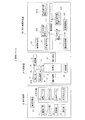
図1は、実施の形態(1)に係る塗布システムの概略構成を示したブロック図である。塗布システム1は、塗布装置10、乾燥装置30、及び光照射装置としての紫外線照射装置100を含んで構成されている。
塗布システム1を構成する塗布装置10は、基板の端面、又は該端面を含む周縁部(例えば、幅1mm〜10mm前後)に液剤を塗布するための装置である。被塗布対象となる基板には、略矩形形状をした薄形(数十μm〜数百μm)の銅張積層基板(パッケージ基板ともいう)、アルミ基板、ガラス基板等の種々の基板が含まれる。
FIG. 1 is a block diagram showing a schematic configuration of a coating system according to the embodiment (1). The coating system 1 includes a coating device 10, a drying
The coating apparatus 10 constituting the coating system 1 is an apparatus for applying a liquid agent to an end face of a substrate or a peripheral portion including the end face (for example, a width of about 1 mm to 10 mm). Substrates to be coated include various substrates such as thin (several tens of μm to several hundreds of μm) copper-clad laminated substrates (also referred to as package substrates), aluminum substrates, glass substrates, and the like having a substantially rectangular shape. .
また、前記液剤(膜形成液、基板コーティング剤ともいう)は、基板の端面や周縁部に塗膜(例えば、硬化後の膜厚が、10μm〜200μm前後)を形成して、基板の端面部分の崩壊による塵埃の発生を防止するとともに、前記塗膜により基板の周縁部を補強して、後工程における基板の取扱性を高め、基板の不良品発生率を低下させるために使用されるものである。
前記液剤としては、基板処理工程(エッチング工程やメッキ工程など)で剥がれない特性(酸及び/又はアルカリに対する耐性)があり、基板表面への付着性等に優れるように複数の樹脂成分が混合されたもの、例えば、水系媒体の溶剤に対し、水性ウレタン樹脂、水性スチレン樹脂及び水性増粘剤を含むコーティング剤など、目的用途に応じて調製された液剤などが使用できる。また、前記液剤を塗布する膜厚に応じて適宜粘度を調整する、例えば、膜厚を薄くする場合は粘度を下げることが好ましい。
Further, the liquid agent (also referred to as a film forming liquid or a substrate coating agent) forms a coating film (for example, a film thickness after curing of about 10 μm to 200 μm) on the end surface or peripheral portion of the substrate, and the end surface portion of the substrate It is used to prevent the generation of dust due to the collapse of the substrate, and to reinforce the peripheral portion of the substrate with the coating film, to improve the handleability of the substrate in the subsequent process, and to reduce the defective product occurrence rate of the substrate is there.
The liquid agent has a characteristic (resistance to acid and / or alkali) that does not peel off in a substrate processing process (such as an etching process or a plating process), and a plurality of resin components are mixed so as to have excellent adhesion to the substrate surface. For example, a liquid agent prepared according to the intended use, such as a coating agent containing an aqueous urethane resin, an aqueous styrene resin and an aqueous thickener, can be used for the solvent of the aqueous medium. Moreover, it is preferable to adjust a viscosity suitably according to the film thickness which apply | coats the said liquid agent, for example, when making a film thickness thin, it is preferable to reduce a viscosity.
塗布装置10は、基板を搬送するコンベア部11、コンベア部11で基板の位置決めを行う位置決め部12、基板移載部13、塗布部20、各部の駆動動作等を制御する制御部14、及び作業者が必要な操作を行うための操作部15などを含んで構成されている。
The coating apparatus 10 includes a conveyor unit 11 that transports a substrate, a
位置決め部12は、コンベア部11の両側に設けられた位置決めガイド部(図示せず)を備え、基板を挟み込む方向に前記位置決めガイド部を移動させて基板を挟み、基板を所定位置に位置決め配置する機能を備えている。前記位置決めガイド部の内側面には、基板を傷つけることなく把持するための部材が配設されている。
The
塗布部20は、基板を支持する支持テーブル21と、支持テーブル21の周囲に配設された1台以上、例えば4台の塗布ユニット22と、これら塗布ユニット22を支持テーブル21の各辺に沿ってそれぞれ移動させる移動ユニット23とを備えている。各塗布ユニット22には、例えば、基板の端部を挿入し得る隙間を有して上下に対向配置される上側ヘッド及び下側ヘッドを備えた一対の塗布ヘッド(図示せず)が装備されている。
さらに塗布部20には、塗布ユニット22の各塗布ヘッドに樹脂成分を含む膜形成液を供給する液供給ユニット24が装備されている。移動ユニット23は、例えば、塗布ユニット22を2軸(XY軸)方向に水平移動させる2軸(XY軸)直動機構で構成することができる。
The application unit 20 includes a support table 21 that supports the substrate, one or more, for example, four
Further, the coating unit 20 is equipped with a
前記一対の塗布ヘッドは、例えば、当該一対の塗布ヘッドの対向面に、膜形成液を溜める液溜部と、該液溜部を通過させた基板の端部に付着した膜形成液を薄膜状に塗工する塗工部と(いずれも図示せず)を備えた構成とすることができる。また、前記塗工部は、例えば、基板の端部に付着した前記膜形成液をならす(均す)こて(鏝)部と、該こて部を通過させた前記基板の端部に付着した余分な膜形成液を掻き取る掻取部と(いずれも図示せず)を備えた構成とすることができる。 The pair of coating heads, for example, has a liquid reservoir portion that stores a film-forming liquid on opposite surfaces of the pair of coating heads, and a film-forming liquid that adheres to the end of the substrate that has passed through the liquid reservoir. It can be set as the structure provided with the coating part (all are not shown in figure) to apply. In addition, the coating part adheres to, for example, a squeezing (smoothing) part of the film forming liquid adhering to the end part of the substrate and an end part of the substrate passing through the trowel part. A scraper that scrapes off the excess film forming liquid and (both not shown) can be provided.
なお、塗布ユニット22は、前記一対の塗布ヘッドを備えたものに限定されない。例えば、別の実施の形態では、塗布ユニット22として、外周面に環状溝が形成された、円盤状、円柱状、又は略円錐台形状などをした塗布ローラを備えたもの、或は、基板の端部を挟み得るように対向配置された一対の塗布ローラを備えたものなどが採用され得る。
The
また、前記一対の塗布ヘッドの退避位置に塗布ヘッド用保護具(図示せず)が設定されていてもよい。該塗布ヘッド用保護具は、例えば、前記一対の塗布ヘッドの隙間に当接させるパッド部と、該パッド部の下方に配設される液受け部と、前記パッド部及び前記液受け部を支持する支持部とを備えて構成することができる(いずれも図示せず)。この塗布ヘッド用保護具は、図示しない昇降機構によって、塗布時は支持テーブル21の下方に降下し、退避時に前記一対の塗布ヘッドの位置まで上昇して、パッド部が前記一対の塗布ヘッドの正面の隙間部分に当接されるようになっている。 Further, an application head protector (not shown) may be set at the retracted position of the pair of application heads. The protective device for the coating head, for example, supports a pad portion that is brought into contact with a gap between the pair of coating heads, a liquid receiving portion disposed below the pad portion, and the pad portion and the liquid receiving portion. (Not shown). This protective device for the coating head is lowered by a lifting mechanism (not shown) below the support table 21 at the time of coating, and lifted to the position of the pair of coating heads at the time of retraction, so that the pad portion is in front of the pair of coating heads. It comes to contact | abut to the clearance gap part.
また、液供給ユニット24は、膜形成液が収容される液収容部と、液収容部から各塗布ヘッドに膜形成液を供給する電動式ポンプと、塗布ヘッドの液受け部で受けた膜形成液を液収容部に移送(回収)する電動式ポンプと(いずれも図示せず)を含んで構成されている。
The
制御部14は、位置決め部12における搬送・位置決め制御、基板移載部13による基板の移載制御、移動ユニット23のXY軸直動制御、及び液供給ユニット24のポンプの駆動制御など、塗布装置10各部の制御を行う機能を有しており、マイコン、ドライバ回路、記憶部及び電源部など(いずれも図示せず)を含んで構成されている。なお、制御部14は1つ又は複数の制御ユニット(例えば、搬入・位置決め制御用、塗布部制御用等)で構成することができる。
また、制御部14は、前記一対の塗布ヘッドの隙間に、支持テーブル21に支持された基板の4辺の端部をそれぞれ挿し込み、その状態で各塗布ヘッドを基板の周縁部に沿って移動させるように移動ユニット23を駆動制御する機能を有している。
The control unit 14 is a coating apparatus such as transport / positioning control in the
Further, the control unit 14 inserts the edge portions of the four sides of the substrate supported by the support table 21 into the gap between the pair of coating heads, and moves each coating head along the peripheral edge portion of the substrate in that state. It has the function to drive-control the
操作部15は、図示しない液晶操作パネルを備えている。前記液晶操作パネルを通じて、塗布装置10の各部の動作条件の設定、各部の動作指示、動作モード(手動、自動など)の切り替えなどの各種操作を行うことが可能となっている。前記液晶操作パネルを介して入力された操作信号や設定信号が制御部14などに送信されるようになっている。
The
基板移載部13は、コンベア部11で位置決めされた基板を塗布部の支持テーブル21に移載する機能と、塗布部20での塗布処理が完了後、基板を支持テーブル21から乾燥装置30の搬入装置81に移載する機能を備えている。基板移載部13は、基板を吸着するための複数の吸着保持具を備えた1以上の基板保持部と、該基板保持部を基板搬送方向に往復移動させる水平移動機構と、基板保持部を垂直方向に往復移動させる垂直移動機構とを備えている(いずれも図示せず)。前記吸着保持具により基板が吸着保持されるようになっている。
The
次に、塗布システム1を構成する乾燥装置30について説明する。
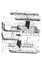
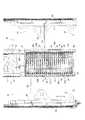
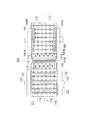
図2は、実施の形態に係る乾燥装置30の一部省略斜視図である。図3は、実施の形態に係る乾燥装置30の開放側面図である。図4は、実施の形態に係る乾燥装置30の内部構造を示す概略図であり、(a)は横断面図、(b)は部分側面図である。
Next, the drying
FIG. 2 is a partially omitted perspective view of the drying
乾燥装置30は、基板2を乾燥させる乾燥室31と、乾燥室31に基板2を搬入する搬入装置81と、乾燥室31から基板2を搬出する搬出装置91とを含んで構成されている。
乾燥室31は、基板2が載置される複数段の棚部32と、これら各棚部32に重ねて配置される基板押え部材41と、各棚部32に対応して設けられた略帯板状の搬入用開閉扉51と、各棚部32に対応して設けられた略帯板状の搬出用開閉扉52と、複数段の棚部32に載置される基板2の各辺に沿った一定方向に風(例えば、熱風)を送り出す送風部62と、乾燥室31内の気体を吸引する吸引部63とを備えている。
搬入装置81は、棚部32と基板押え部材41との間に基板2を搬入するように構成され、搬出装置91は、棚部32と基板押え部材41との間から基板2を搬出するように構成されている。
The drying
The drying
The carry-in
制御部40は、搬入装置81や搬出装置91の駆動制御、送風機72や吸引機74の駆動制御など、乾燥装置30の各部の制御を行う機能を有しており、マイコン、ドライバ回路、記憶部及び電源部など(いずれも図示せず)を含んで構成されている。なお、制御部40は1つ又は複数の制御ユニット(例えば、搬入装置制御用、搬出装置制御用、送風機制御用、吸引機制御用等)で構成することができる。
The
棚部32は、搬入用開閉扉51の手前に設けられた帯板状の搬入側下枠部33と、搬出用開閉扉52の手前に設けられた帯板状の搬出側下枠部34と、搬入側下枠部33と搬出側下枠部34との間に架設された複数(本実施の形態では5本)の桟部材(金属製の細い角材)36とを含んで構成されている。
The
搬入装置81は、基板2が載置される搬入用フォーク部(フォーク形状部)82と、搬入用フォーク部82を昇降させる昇降機構86と、搬入用フォーク部82を水平方向に移動させる水平移動機構87とを備えている。
The
搬出装置91は、基板2が載置される搬出用フォーク部(フォーク形状部)92と、搬出用フォーク部92を昇降させる昇降機構96と、搬出用フォーク部92を水平方向に移動させる水平移動機構97とを備えている。
The carry-out
昇降機構86、96には、バランスウェイト(つり合い錘)を用いた滑車機構が設けられ、少ない動力で搬入用フォーク部82や搬出用フォーク部92の昇降動作が可能となっている。水平移動機構87、97は、図示しない固定レール上をスライド移動可能な直動機構などにより構成されている。
搬入用フォーク部82と搬出用フォーク部92とは、複数の桟部材36の間を昇降可能に構成されている。すなわち、搬入用フォーク部82及び搬出用フォーク部92と、複数の桟部材36とが平面視互い違いの位置関係となるように配置構成されている。
The elevating
The carry-in
搬入用フォーク部82及び搬出用フォーク部92は、2本の外側フォーク部83、93と、外側フォーク部83、93の内側に設けられた複数(この場合、4本)の内側フォーク部84、94とを含んで構成され、内側フォーク部84、94には、基板2を吸着させるための吸着機構85、95が設けられている。外側フォーク部83、93の先端部は、傾斜状をした樹脂材料で形成されている。
吸着機構85、95は、内側フォーク部84、94の上面に形成された複数の吸着孔、内側フォーク部84、94の内部に、吸着孔に接続するように設けられた吸着ノズル(図示せず)などを含んで構成されている。
The carry-in
The
搬入側下枠部33に搬入用開閉扉51が蝶番等の取付具(図示せず)を用いて起倒回動可能に取り付けられ、搬出側下枠部34に搬出用開閉扉52が蝶番等の取付具(図示せず)を用いて起倒回動可能に取り付けられている。
搬入用開閉扉51の下辺部の両端に、搬入用フォーク部82の外側フォーク部83先端部で押下げ可能な押下片51aが突出した状態で形成され、搬出用開閉扉52の下辺部の両端に、搬出用フォーク部92の外側フォーク部93先端部で押下げ可能な押下片52aが突出した状態で形成されている。
A loading opening / closing
At both ends of the lower side portion of the loading opening / closing
搬入用開閉扉51の両側には、縦長細帯形状をした搬入側縦枠部38が搬入側下枠部33に固定された状態で配設され、搬出用開閉扉52の両側には、縦長細帯形状をした搬出側縦枠部39が搬出側下枠部34に固定された状態で配設されている。
搬入用開閉扉51が閉じている状態で、搬入用開閉扉51と搬入側縦枠部38とが磁力で互いに引き合うように、搬入用開閉扉51の両端部と、搬入側縦枠部38の両端部と対面する箇所に磁石51b、38aがそれぞれ設けられている。
また、搬出用開閉扉52が閉じている状態で、搬出用開閉扉52と搬出側縦枠部39とが磁力で互いに引き合うように、搬出用開閉扉52の両端部と、搬出側縦枠部39の両端部と対面する箇所とに磁石52b、39aがそれぞれ設けられている。
On both sides of the loading opening / closing
In a state in which the loading opening / closing
Further, in the state where the unloading opening / closing
基板押え部材41は、基板2を押えるための略矩形形状をした枠部42と、枠部42から基板2の搬入方向と交差する方向に張り出して設けられた複数の薄板状の張出部43と、これら張出部43に、基板2の搬入方向に回転可能に取り付けられた複数の回転部材44と含んで構成されている。枠部42は、金属製の細角材で構成されている。基板押え部材41の重量は、1kg程度とすることができる。
回転部材44には、小型のベアリング部材を使用することができ、張出部43に形成された軸部に前記ベアリングが回転可能に挿着されている。
基板押え部材41のこれら複数の回転部材44が、搬入用フォーク部82の外側フォーク部83、及び搬出用フォーク部92の外側フォーク部93の上にそれぞれ乗り上げ可能となっている。
The
A small bearing member can be used for the rotating
The plurality of rotating
搬入側下枠部33、及び/又は搬出側下枠部34の両端部に、基板押え部材41の回転部材44の水平方向に対する位置ずれを規制する位置規制具35が設けられている。
位置規制具35には、例えば、回転部材44の水平方向に対する位置ずれを規制できる平面視凸部(凸状部)35aが形成されている。位置規制具35の形状は、回転部材44の水平方向に対する位置ずれを規制できる一方、回転部材44の鉛直方向に対する移動が可能な形状、かつ搬入側下枠部33や搬出側下枠部34に取り付け可能な形状あれば特に限定されない。
At both ends of the carry-in side
The
基板2の搬入時や搬出時に、搬入用フォーク部82や搬出用フォーク部92により基板押え部材41が持ち上げられた場合、持ち上げ機構46により基板押え部材41が持ち上げられた場合などに、一段上の搬入側下枠部33及び搬出側下枠部34の位置規制具35の凸部35aと、持ち上げられた基板押え部材41の四隅に設けられた回転部材44の外側面とが当接し、回転部材44の水平外側方向に対する位置ずれが規制されるようになっている。
When the
桟部材36は、搬入側下枠部33及び/又は搬出側下枠部34に対して、桟部材36の長手方向に遊びを持たせて固定する固定部37を備えている。
固定部37は、例えば、桟部材36の両端に固定された階段形状の固定部材、該固定部材に形成された長孔、該長孔に配置された筒状のスペーサ、該スペーサを介して、搬入側下枠部33又は搬出側下枠部34に固定する固定具(ネジ部材)とを含んで構成されているが、この構成に限定されない。
また、乾燥室31の上面にも桟部材36が設けられている。乾燥室31上面に桟部材36が設けられていることにより、基板2を、乾燥室31を通過させずに、紫外線照射装置100に搬送することも可能となっている。
The
The fixing
A
乾燥室31には、各棚部32に載置された全ての基板押え部材41を、各棚部32から一度に持ち上げる持ち上げ機構46が装備されている。持ち上げ機構46は、搬入側下枠部33の両側、及び搬出側下枠部34の両側に配設され、各基板押え部材41の一部、すなわち、枠部42四隅の張出部43に設けられた回転部材44の軸部を係止させる係止部47aを備えた昇降用縦枠部材47と、昇降用縦枠部材47を昇降させるための駆動ハンドルや昇降機構(図示せず)とを含んで構成することができる。
The drying
また、乾燥室31内への基板押え部材41の出し入れには、専用の支持具98が使用される。支持具98は平面視略コの字形状に形成され、乾燥室31の開閉扉61を開けた状態で、基板搬入方向と交差する方向から、桟部材36と基板押え部材41との間に挿入し、支持具98の上に基板押え部材41を載せた状態で、乾燥室31から支持具98を引き出すことにより、基板押え部材41を乾燥室31から取り出すことができるようになっている。また、基板押え部材41を乾燥室31内の各棚部32に載置する場合は、取り出し時と逆の動作により行う。すなわち、支持具98の上に基板押え部材41を載せた状態で、支持具98を乾燥室31の棚部32の上に水平に挿入し、所定位置まで挿入後、支持具98を引き抜きながら、基板押え部材41を棚部32の上に載置すればよい。
Further, a
乾燥室31における基板搬入方向と交差する向きの両側面には、観音開き式の開閉扉61が設けられている。開閉扉61の内側(乾燥室31内)に、送風部62と吸引部63とが設けられている。
送風部62は、開閉扉61の内側に設けられた縦型の送風用筒状部62aと、送風用筒状部62aの側面に突出した状態で(略口ばし状に)設けられた縦長の吹き出し口62bとを備え、送風用筒状部62aの上部が、送風ダクト71を介して送風機(ブロア装置)72に接続されている。送風機72は、乾燥室31の外部(上方)に配置され、熱風(〜80℃)を送り出すことが可能となっている。
A double door opening / closing
The
送風用筒状部62aは、乾燥室31内と略同じ高さに形成され、吹き出し口62bは、乾燥室31内と略同じ高さ(縦長)で細幅のスリット状に形成され、棚部32に載置された基板の各辺に沿う向きに向けられ、乾燥室31の内壁面に沿った一定方向に気流(循環流)が形成されるようになっている。また、吹き出し口62bは、そのスリット幅(約1mm〜)を調整することが可能となっている。
The blower
吸引部63は、開閉扉61の内側に設けられた縦型の吸引用筒状部63a(空洞部)と、吸引用筒状部63aの側面に設けられた縦長の吸引口63bとを備え、吸引用筒状部63aの上部が、吸引ダクト73を介して吸引機(吸引ファン等)74に接続されている。
吸引用筒状部63aは、乾燥室31内と略同じ高さに形成され、吸引口63bは、乾燥室31内と略同じ高さ(縦長)で細幅のスリット状に形成されている。吸引口63bは、スリット幅調整板63cをずらすことにより、そのスリット幅(約1mm〜)を調整することが可能となっている。
吸引機74と送風機72とはダクト76で接続されており、吸引機74で吸引された気体が送風機72に送り出され、乾燥室31内の気体(熱風)が循環できるように構成されている。
The
The suction
The
乾燥室31には、内部の気体を外部に排出するための排気部64が設けられている。排気部64は、乾燥室31の開閉扉61の上部に設けられた排気孔64aと、排気孔64aに接続された排気ダクト77とを含んで構成され、排気ダクト77は、例えば、工場内の排気機構78に接続されるようになっている。また、吸引機74には、外気を取り込む外気取込み部(取り込み弁)75が装備されている。排気部64により乾燥室31内の一部の気体が排気可能に構成され、吸引機74に設けられた外気取込み部75により外気を適宜取り込み可能に構成され、乾燥室31内の湿度等の状態が調整可能となっている。
The drying
実施の形態に係る乾燥装置30の動作について説明する。
まず、乾燥室31に基板2を搬入する動作について説明する。図5は、実施の形態に係る乾燥装置30の基板搬入動作を説明するための図である。
塗布装置10で、基板の端面又は該端面を含む周縁部への液剤の塗布処理が完了すると、塗布装置10の基板移載部13によって、基板2が搬入装置81の搬入用フォーク部82の上に移送されて、搬入用フォーク部82の内側フォーク部84の上に載置される。このとき、基板2は、吸着機構85により内側フォーク部84に吸着された状態で保持される。
Operation | movement of the drying
First, an operation for carrying the
When the coating apparatus 10 completes the application of the liquid agent to the end face of the substrate or the peripheral portion including the end face, the
搬入用フォーク部82に基板2が載置されると、乾燥室31への搬入動作に移る。制御部40が、乾燥室31内への基板2の搬入・搬出状態(履歴)に基づいて、基板2を載置する棚部32を決定し、該棚部32が設けられている高さ位置の搬入用開閉扉51の正面位置まで搬入用フォーク部82を昇降移動させる(図5(a))。
When the
次に搬入用フォーク部82を搬入用開閉扉51の方向に水平移動させて、搬入用フォーク部82の外側フォーク部83で搬入用開閉扉51を乾燥室31の内側に押し倒し、搬入用開閉扉51を開けた状態にする。外側フォーク部83の先端部上面の高さ位置を、基板押え部材41の回転部材44が乗り上げ可能な位置、かつ桟部材36の上面よりも高くなる位置に微調整した後、搬入用フォーク部82を水平方向に移動させる。
Next, the
搬入用フォーク部82の水平移動に伴い、基板押え部材41の回転部材44が外側フォーク部83の上に順次乗り上げていき、桟部材36の間に内側フォーク部84が挿入されていく。
基板押え部材41の回転部材44は枠部42よりも下に位置しているため、外側フォーク部83の上に基板押え部材41の回転部材44が乗り上げた状態では、内側フォーク部84上面と枠部42下面との間に、隙間(回転部材44の枠部42下方への張り出し分の隙間)が形成され、また、内側フォーク部84上面が桟部材36の上面より高い位置にあるため、この隙間に基板2が挿入されるようになっている(図5(b))。
With the horizontal movement of the
Since the rotating
基板押え部材41の全ての回転部材44が外側フォーク部83に乗り上げて、搬入用フォーク部82の先端部が搬出用開閉扉52手前の所定位置まで到達すると、次に搬入用フォーク部82を降下させる。
搬入用フォーク部82の降下に伴い、まず、内側フォーク部84上の基板2が桟部材36の上に載置され、次に、基板押え部材41の枠部42が基板2の上に載置される。この時、基板2の周縁部は、桟部材36及び基板押え部材41の枠部42からはみ出した状態となっている。その後、基板押え部材41の回転部材44が外側フォーク部83から離れる位置まで搬入用フォーク部82を降下させる(図5(c))。
When all the
As the
次に搬入用フォーク部82を搬入方向と逆向きに水平移動させて、乾燥室31から搬入用フォーク部82を引き出す。外側フォーク部83の先端部が、搬入用開閉扉51の押下片51aの上部に到達すると、搬入用フォーク部82を少し降下させて、外側フォーク部83の先端部で押下片51aを押下げる。該押下げ動作に伴い、内側に倒れていた搬入用開閉扉51が起き上がり、搬入用開閉扉51が閉じられる。その後、搬入用フォーク部82を所定の位置まで退避させて、搬入動作を終える。
Next, the
次に乾燥室31での乾燥動作について説明する。
ヒーター機能を有する送風機72からの熱風(例えば、80℃程度の空気)が送風ダクト71を介して乾燥室31の四隅に配置された送風部62の送風用筒状部62aにそれぞれ送り込まれる。
送風用筒状部62aに導入された熱風は、送風用筒状部62aの縦長スリット状の吹き出し口62bから吹き出される。送風部62が乾燥室31の四隅に配置され、送風用筒状部62aの吹き出し口62bが基板の各辺に沿った一定方向に向けられているため、基板の4辺(乾燥室31の内壁面)に沿った一定方向に流れる気流(循環流)が生成される。
Next, the drying operation in the drying
Hot air (for example, air of about 80 ° C.) from the
The hot air introduced into the blowing
また、乾燥室31内の熱風の一部が、吸引用筒状部63aに形成された縦長スリット状の吸引口63bから吸引され、吸引ダクト73を介して吸引機74に送り込まれる。吸引機74で吸引された熱風は、送風機72に送り込まれるようになっている。また、乾燥室31に設けられた排気孔64aから、乾燥室31内の気体が適宜排気されると共に、吸引機74に設けられた吸気弁から外気が適宜導入され、乾燥室31内の湿度や温度などの条件が調整されるようになっている。
In addition, a part of the hot air in the drying
次に、乾燥室31から基板2を搬出する動作について説明する。図6は、実施の形態に係る乾燥装置30の基板搬出動作を説明するための図である。
基板2が乾燥室31に搬入された後、所定の乾燥時間が経過すると、基板2の搬出動作が開始される。乾燥室31内への基板2の搬入状態(履歴)に基づいて、搬出する基板2が載置されている棚部32を判断し、該棚部32が設けられている高さ位置の搬出用開閉扉52の正面位置まで搬出用フォーク部92を昇降移動させる。
Next, an operation for unloading the
After the
次に搬出用フォーク部92を搬出用開閉扉52の方向に水平移動させて、搬出用フォーク部92の外側フォーク部93で搬出用開閉扉52を乾燥室31の内側に押し倒し、搬出用開閉扉52を開けた状態にする。外側フォーク部93の先端部上面の高さ位置を、基板が載置されている桟部材36の上面より下になる位置に調整した後、搬出用フォーク部92を水平方向に移動させる(図6(a))。
Next, the unloading
搬出用フォーク部92の先端部が、搬入用開閉扉51手前の所定位置に到達すると、次に搬出用フォーク部92を上昇させる。搬出用フォーク部92の上昇に伴い、まず、基板押え部材41の回転部材44が外側フォーク部93の上に載り、基板押え部材41が、基板2が載置された桟部材36から持ち上げられていく。さらに上昇させると、桟部材36に載置されている基板2が内側フォーク部94の上に載置される。なお、内側フォーク部94に設けた吸着機構95により、基板2は、内側フォーク部94に吸着された状態で保持される(図6(b))。
When the leading end of the unloading
次に搬出用フォーク部92を逆向きに水平移動させて、乾燥室31から搬出用フォーク部92を引き出す。搬出用フォーク部92を引き出す動作を開始すると、外側フォーク部93に乗り上げていた基板押え部材41の回転部材44が、外側フォーク部93から順次外れてゆき、基板押え部材41の枠部42が、桟部材36の上に載置されるようになっている(図6(c))。
Next, the unloading
そして、外側フォーク部93の先端部が、搬出用開閉扉52の押下片52aの上部に到達すると、搬出用フォーク部92を少し降下させて、外側フォーク部93の先端部で押下片52aを押下げる。該押下げ動作に伴い、内側に倒れていた搬出用開閉扉52が起き上がり、搬出用開閉扉52が閉じられる。その後、搬出用フォーク部92を所定の位置まで退避させて、搬出動作を終える(図6(d))。搬出用フォーク部92上の基板2は、その後、基板移載部101により紫外線照射装置100に移送されるようになっている。
When the front end of the
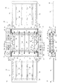
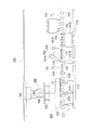
次に塗布システム1を構成する光照射装置としての紫外線照射装置100について説明する。図7は、実施の形態に係る紫外線照射装置100の内部構造を示した概略平面図である。図8は、実施の形態に係る紫外線照射装置100の内部構造を示した概略側面図である。
紫外線照射装置100は、紫外線硬化剤などを含む液剤が塗布された基板の端面又は該端面を含む周縁部に紫外線を照射して、塗膜を硬化・乾燥させるための装置である。
紫外線照射装置100は、基板2を移送する基板移載部101と、基板2を搬送する搬送装置111と、搬送装置111で搬送される基板2の位置決めを行う位置決め装置121と、基板2の搬送方向と交差する向きに配設された第1の紫外線照射ユニット131A、131Bと、基板2の搬送方向と平行する向きに配設された第2の紫外線照射ユニット141A、141Bと、搬送装置111で搬送される基板の搬送位置を検出する複数の基板検出センサ151〜154とを含んで構成されている。図7、8中の矢印は基板2の搬送方向を示している。
Next, the
The
The
さらに、紫外線照射装置100は、基板検出センサ151〜154により検出される基板2の搬送位置に基づいて、第1の紫外線照射ユニット131A、131B及び第2の紫外線照射ユニット141A、141Bの照射制御を行う照射制御部161と、基板検出センサ151〜154により検出される基板2の搬送位置に基づいて、搬送装置111による基板の搬送速度を制御する搬送制御部171とを備えている。
Furthermore, the
基板移載部101は、乾燥装置30から搬送装置111に基板2を移載する機能を備えている。基板移載部101は、基板保持部102と、基板保持部102を基板搬送方向に往復移動させる水平移動機構104と、基板保持部102を垂直方向に往復移動させる垂直移動機構105とを備えている。また、基板保持部102には、基板2を吸着保持する吸着保持具103が配設されている。吸着保持具103は、吸着ノズルなどで構成され、図示しないエアチューブを介して真空ポンプに連結されている。
The
搬送装置111は、基板2との接触面積が少なくなるように、細幅のローラ(車輪部)112が所定間隔を設けて配設されたローラ式のコンベア装置が採用され、複数のローラ112を備えたコンベア部113と、これらローラ112の間に昇降可能に配設された基板持上げ部114と含んで構成されている。また、第1の紫外線照射ユニット131A、131Bの前後には、搬送される基板2の落下を防止するための落下防止板115がローラ112の上端部のみを臨ませた状態で配設されている。また落下防止板115の表面には、基板2の搬送を補助するための小型のベアリング(回転)部材116が複数配設されている。
The conveying
位置決め装置121は、第1の紫外線照射ユニット131A、131B及び第2の紫外線照射ユニット141A、141Bによる紫外線照射を行う前段で基板2の位置決めを行うために設けられている。位置決め装置121は、乾燥装置30から搬送装置111上に移送されてきた基板2の位置決め(位置調整)を行う位置決めガイド部122と、位置決めガイド部122を所定方向に駆動させる駆動部123とを含んで構成されている。
The
位置決め装置121による基板2の位置決め工程は、乾燥装置30から搬送装置111の上に基板を移送した後、基板持上げ部114により基板2をローラ112から一旦持ち上げた状態にする。その後、コンベア部113の両側に設けられた位置決めガイド部122を、基板2を挟み込む方向に所定位置まで移動させて、基板2を位置決めガイド部122で挟むようにして所定位置に位置決めする。位置決め後、基板持上げ部114を降下させて、基板2をローラ112上に配置して終了する。位置決めガイド部122の内側面には、基板2を傷つけることなく把持するための部材を配設してもよい。
In the positioning process of the
第1の紫外線照射ユニット131A、131Bは、搬送装置111の上下位置に1台ずつ、上方向と下方向への照射角度を所定角度ずらした状態で配置され、照射部132には、多数個の紫外線照射用LEDが列設されている。第1の紫外線照射ユニット131A、131Bは、基板2の搬送方向と交差する向きに配設され、該交差する向きの基板2の端面や周縁部に紫外線を照射するためのものであり、照射制御部161により照射状態(ON/OFF)の切替等の制御が可能になっている。第1の紫外線照射ユニット131A、131Bが、上方向と下方向への照射角度を所定角度ずらした状態で配設することにより、互いの照射部132を保護することが可能となっている。
The first
第2の紫外線照射ユニット141A、141Bは、搬送装置111の上下に1台ずつ、上方向と下方向への照射位置を搬送方向にずらした状態で配置され、照射部142には、多数個の紫外線照射用LEDが列設されている。第2の紫外線照射ユニット141A、141Bは、搬送装置111の両側(基板の搬送方向と平行する向き)に配設され、該平行する向きの基板2の端面や周縁部に紫外線を照射するためのものであり、照射制御部161により照射状態(ON/OFF)の切替等の制御が可能となっている。
前記紫外線照射用LEDには、例えば、350nm〜400nm前後、好ましくは360nmの波長、指向角が30°前後のものを使用することが好ましいが、これに限定されない。
The second
For example, a LED having a wavelength of about 350 nm to about 400 nm, preferably about 360 nm, and a directivity angle of about 30 ° is preferably used as the LED for ultraviolet irradiation, but is not limited thereto.
第1の紫外線照射ユニット131A、131Bや第2の紫外線照射ユニット141A、141Bの周辺部には、搬送されてくる基板2を検知するための複数の基板検知センサ151〜154が設置されている。基板検知センサ151〜154は、例えば、光センサや赤外線センサ、画像センサなどで構成することができる。
A plurality of
照射制御部161は、これら基板検出センサ151〜154により検出される基板2の搬送位置に基づいて、すなわち基板2の端部が、第1の紫外線照射ユニット131A、131Bと第2の紫外線照射ユニット141A、141Bのそれぞれの照射域を通過するタイミングで、第1の紫外線照射ユニット131A、131Bと第2の紫外線照射ユニット141A、141Bの照射ON/OFF制御を行う機能を有している。照射制御部161は、マイコン、ドライバ回路、記憶部及び電源部など(いずれも図示せず)を含んで構成されている。なお、照射制御部161は1つ又は複数の制御ユニットで構成することができる。
The
搬送制御部171は、基板2の搬送方向と交差する向きの基板2の端面が第1の紫外線照射ユニット131A、131Bの照射域を通過する第1の速度と、基板の搬送方向と平行する向きの基板2の端面が第2の紫外線照射ユニット141A、141Bの照射域を通過する第2の速度とを制御する。搬送制御部171では、第1の速度が第2の速度より小さくなるように搬送制御が実行されるようになっている。搬送制御部171は、マイコン、ドライバ回路、記憶部及び電源部など(いずれも図示せず)を含んで構成されている。なお、搬送制御部171は1つ又は複数の制御ユニットで構成することができる。
The
実施の形態に係る紫外線照射装置100の動作について説明する。
基板移載部101を駆動させて、乾燥装置30の搬出装置91(搬出用フォーク部92)から搬送装置111のローラ112上に基板を移送し、基板2をローラ112に載置する。
次に搬送装置111の基板持上げ部114と、位置決め装置121とを駆動させて、基板2を所定の位置、すなわち、基板2の搬送方向と平行な向きの基板両辺の位置が、第2の紫外線照射ユニット141A、141Bの照射部142と一致するように位置決めする。
An operation of the
The
Next, the
該位置決め後、基板2がローラ112に載置されて搬送装置111が駆動される。第1の紫外線照射ユニット131A、131Bの手前で、基板検出センサ151により基板2が検知されると、第1の紫外線照射ユニット131A、131Bによる照射が開始されるとともに、基板2の搬送速度が第1の速度(例えば、5mm/sec)に制御され、搬送方向に対して前方の基板2の端面及び該端面を含む周縁部に紫外線が照射される。
After the positioning, the
その後、基板検出センサ152により、第1の紫外線照射ユニット131A、131Bの間を通過した基板2が検知されると、第1の紫外線照射ユニットによる照射を終了するとともに、基板2の搬送速度が第2の速度(例えば、60mm/sec)に制御される。
Thereafter, when the
その後、第2の紫外線照射ユニット141A、141Bの手前で、基板検出センサ153により基板が検知されると、第2の紫外線照射ユニット141A、141Bによる照射が開始され、搬送方向に対して両側の基板2の端面及び該端面を含む周縁部に紫外線が照射される。
After that, when the substrate is detected by the
その後、第1の紫外線照射ユニット131A、131Bの手前で、基板検出センサ151により基板2が検知されなくなる(基板2が通過して非検知状態になる)と、再度、第1の紫外線照射ユニット131A、131Bによる照射が開始されるとともに、基板2の搬送速度が第1の速度に制御され、搬送方向に対して後方の基板2の端面及び該端面を含む周縁部に紫外線が照射される。
After that, when the
その後、基板検出センサ152により、第1の紫外線照射ユニット131A、131Bの間を通過した基板2が検知されなくなる(基板2が通過して非検知状態になる)と、第1の紫外線照射ユニット131A、131Bによる照射を終了するとともに、基板の搬送速度が第2の速度に制御される。
Thereafter, when the
その後、基板検出センサ154により、第2の紫外線照射ユニット141A、141Bを通過した基板が検知されなくなる(基板が通過して非検知状態になる)と、第2の紫外線照射ユニット141A、141Bによる照射を終了し、その後、基板2が搬送装置111により、紫外線照射装置100の外に搬送されたことが外部センサで検知されると、搬送装置111の駆動が停止される。
Thereafter, when the substrate that has passed through the second
上記実施の形態に係る乾燥装置30によれば、乾燥室31の各棚部32に一枚ずつ基板2を搬入出することができるとともに、乾燥室31に複数の基板2を収容することができ、装置の省スペース化、小型化を図ることができる。また、乾燥中は、基板押え部材41で基板2が適切に押えられるため、搬入出時や乾燥時に送風による基板2の浮き上りや位置ずれを防止することができ、また、送風部62により、基板2の各辺(端面や周縁部)に効率良く風を吹き付けることができ、基板2の端面や周縁部に塗布された液剤を効率よく、しかもきれいに乾燥させることができる。
According to the drying
また、乾燥装置30によれば、搬入用フォーク部82と搬出用フォーク部92とが、複数の桟部材36の間を昇降可能に構成されているので、基板1枚当りの搬入出に必要な高さを50mm以下(40mm〜50mm程度)に抑えることができ、24枚程度収納可能な乾燥室31でも、その高さを120〜130cm程度の高さに抑えることができ、コンパクトかつメンテナンス性に優れた装置とすることができる。
Further, according to the drying
また、乾燥装置30によれば、搬入用開閉扉51と搬出用開閉扉52の開閉動作を搬入用フォーク部82と搬出用フォーク部92の動作で行うので、搬入用開閉扉51と搬出用開閉扉52を開閉するための個別の動力が不要となり、装置の省エネ化を図ることができる。
Further, according to the drying
また、乾燥装置30によれば、搬入用開閉扉51と搬出用開閉扉52とが閉じられる際、磁石51b、52b、38a、39aの磁力により、搬入用開閉扉51と搬出用開閉扉52とが、それぞれ搬入側縦枠部38と搬出側縦枠部39とに引き付けられて閉じやすく、また、閉じた状態を磁石の磁力により安定させることができる。
Further, according to the drying
また、乾燥装置30によれば、基板押え部材41の張出部43に設けられた複数の回転部材44が、搬入用フォーク部82の外側フォーク部83、及び搬出用フォーク部92の外側フォーク部93の上にそれぞれ乗り上げ可能に構成されているので、基板押え部材41の上下方向の動作を、搬入用フォーク部82や搬出用フォーク部92の動作で実行することができ、基板押え部材41のための個別の動力が不要となり、装置の省エネ化を図ることができ、また、搬入用フォーク部82の外側フォーク部83や搬出用フォーク部92の外側フォーク部93の上に、基板押え部材41をスムーズに載せることができ、基板2の搬入・搬出動作をスムーズに行わせることができる。
In addition, according to the drying
また、乾燥装置30によれば、搬入側下枠部33、及び/又は搬出側下枠部34に設けられた位置規制具35により回転部材44の水平方向に対する位置ずれが規制され、基板押え部材41の位置ずれを防止することができる。
Further, according to the drying
また、乾燥装置30によれば、桟部材36の固定部37に遊びを持たせているので、例えば、乾燥室31内の熱(熱風)により桟部材36が長手方向に熱膨張しても、該熱膨張による歪みを適切に逃がすことができ、桟部材36の変形などを防止することができる。
Further, according to the drying
また、乾燥装置30によれば、持ち上げ機構46により各棚部32に載置された全ての基板押え部材41を各棚部32から一度に持ち上げることができ、搬入した基板2の位置ずれ等が生じた場合のメンテナンス作業などを容易に行うことができる。
Moreover, according to the drying
また、乾燥装置30によれば、送風部62が、縦型の送風用筒状部62aと縦長の吹き出し口62bとを備えているので、乾燥室31のいずれの高さ位置の棚部32に載置された基板2に対しても、ほぼ同じ条件で均等に効率良く気体を吹き付けることができる。
また、吸引部63が、縦型の吸引用筒状部63aと縦長の吸引口63bとを備えているので、送風部62による乾燥室31内の気体の流れに沿って気体を吸引することができ、送風の流れを一定に保つことができる。また、吸引機74により吸引された気体が送風機72に送り出されるので、乾燥室31内の気体を循環させることができ、特に、温風(熱風)を使用した場合には熱エネルギーの損失を減らすことができ、省エネ化を図ることができる。
Further, according to the drying
Further, since the
また、乾燥装置30によれば、排気機構78により乾燥室31内の気体を必要に応じて外部に排出することができ、また、吸引機構により、外気を適宜取り込むことができ、乾燥室31内の温度や湿度などの条件を適切に調整することができる。
Further, according to the drying
また、上記実施の形態に係る紫外線照射装置100によれば、基板2の端面や周縁部のみに正確に紫外線を照射することができ、基板2の端面や周辺部に塗布された液剤の硬化処理を効率良く実行することができる。また、第1の紫外線照射ユニット131A、131Bと第2の紫外線照射ユニット141A、141Bとが、LED方式の紫外線照射ユニットであるので、紫外線硬化樹脂を含む液剤を短時間で硬化・乾燥させることができ、装置の小型化を図ることができ、さらに、装置の長寿命化及びメンテナンスに係るコストを減らすことができる。
Moreover, according to the
また、照射制御部161と搬送制御部171とにより、基板2の搬送方向と交差する向きの基板2の端面への紫外線照射と、基板2の搬送方向と平行する向きの基板2の端面への紫外線照射とを適切に制御することができ、基板2の全周に渡ってバラツキのない均一な硬化・乾燥処理を行うことができる。
Further, the
なお、上記実施の形態では、光照射装置が紫外線照射装置100である場合について説明したが、本発明に係る光照射装置は、紫外線照射装置100に限定されるものではなく、電子線等の放射線や可視光線で硬化する樹脂を含む液剤が塗布された基板に、放射線や可視光線などの光を照射する装置にも適用可能である。
In addition, although the said embodiment demonstrated the case where a light irradiation apparatus was the
また、上記実施の形態に係る塗布システム1によれば、乾燥時間が短い液剤を使用する場合でも乾燥時間が長い液剤を使用する場合でも、液剤の特性にかかわらず、基板2の端面や周辺部への塗布処理と、乾燥処理とを効率良く行うことができる。また、紫外線硬化剤を含む液剤を使用する場合でも、基板2の端面や周辺部に塗布された液剤の硬化処理を効率良く実行することができ、塗布作業から乾燥・硬化処理の一連の処理を効率良く、省スペースで実現することができる。
In addition, according to the coating system 1 according to the above embodiment, the end face and the peripheral portion of the
なお、上記塗布システム1は、塗布装置10、乾燥装置30、及び紫外線照射装置100で構成されているが、別の実施の形態では、塗布装置10と乾燥装置30で構成された塗布システム、又は塗布装置10と紫外線照射装置100で構成された塗布システムとすることもできる。
In addition, although the said coating system 1 is comprised with the coating device 10, the drying
以上、本発明の実施の形態について説明してきたが、本発明は、上記した実施の形態に限られるものではなく、本発明の要旨を逸脱しない範囲において、本発明の実施の形態に対して種々の変形や変更を施すことができ、そのような変形や変更もまた本発明の技術的範囲に含まれる。また、発明の実施の形態に記載された、作用及び効果は、本発明から生じる最も好適な作用及び効果を列挙したに過ぎず、本発明による作用及び効果は、本発明の実施の形態に記載されたものに限定されるものではない。 Although the embodiments of the present invention have been described above, the present invention is not limited to the above-described embodiments, and various modifications can be made to the embodiments of the present invention without departing from the gist of the present invention. These modifications and changes are also included in the technical scope of the present invention. Further, the actions and effects described in the embodiments of the invention only list the most preferable actions and effects resulting from the present invention, and the actions and effects according to the present invention are described in the embodiments of the present invention. It is not limited to what was done.
1 塗布システム
10 塗布装置
30 乾燥装置
31 乾燥室
32 棚部
41 基板押え部材
51 搬入用開閉扉
52 搬出用開閉扉
62 送風部
63 吸引部
81 搬入装置
82 搬入用フォーク部
91 搬出装置
92 搬出用フォーク部
100 紫外線照射装置(光照射装置)
111 搬送装置
121 位置決め装置
131A、131B 第1の紫外線照射ユニット
141A、141B 第2の紫外線照射ユニット
151、152、153、154 基板検出センサ
161 照射制御部
171 搬送制御部
DESCRIPTION OF SYMBOLS 1 Coating system 10
111 Conveying
Claims (14)
該乾燥室に基板を搬入する搬入手段と、
前記乾燥室から基板を搬出する搬出手段とを備えた乾燥装置であって、
前記乾燥室が、
基板が載置される複数段の棚部と、
これら各棚部に重ねて配置される基板押え手段と、
前記各棚部に対応して設けられた搬入用開閉扉と、
前記各棚部に対応して設けられた搬出用開閉扉と、
前記複数段の棚部に載置される基板の各辺に沿った一定方向に風を送り出す送風手段と、
前記乾燥室内の気体を吸引する吸引手段とを備え、
前記搬入手段が、前記棚部と前記基板押え手段との間に基板を搬入するように構成され、
前記搬出手段が、前記棚部と前記基板押え手段との間から基板を搬出するように構成されていることを特徴とする乾燥装置。 A drying chamber for drying the substrate;
Carrying-in means for carrying the substrate into the drying chamber;
A drying apparatus including unloading means for unloading the substrate from the drying chamber;
The drying chamber is
A plurality of shelves on which substrates are placed; and
Substrate pressing means that are placed on each of these shelves,
An opening / closing door for loading provided corresponding to each of the shelves;
An opening / closing door provided for each of the shelves;
A blowing means for sending wind in a fixed direction along each side of the substrate placed on the plurality of shelves;
A suction means for sucking the gas in the drying chamber;
The carry-in means is configured to carry a substrate between the shelf portion and the substrate pressing means,
The drying apparatus, wherein the unloading unit is configured to unload a substrate from between the shelf and the substrate pressing unit.
前記搬入用開閉扉側に設けられた搬入側下枠部と、
前記搬出用開閉扉側に設けられた搬出側下枠部と、
前記搬入側下枠部と前記搬出側下枠部との間に架設された複数の桟部材とを含み、
前記搬入手段が、
基板が載置される搬入用フォーク部と、
該搬入用フォーク部を昇降させる昇降手段と、
前記搬入用フォーク部を水平方向に移動させる水平移動手段とを備え、
前記搬出手段が、
基板が載置される搬出用フォーク部と、
該搬出用フォーク部を昇降させる昇降手段と、
前記搬出用フォーク部を水平方向に移動させる水平移動手段とを備え、
前記搬入用フォーク部と前記搬出用フォーク部とが、前記複数の桟部材の間を昇降可能に構成されていることを特徴とする請求項1記載の乾燥装置。 The shelf is
A loading-side lower frame portion provided on the loading door side;
An unloading-side lower frame portion provided on the unloading opening / closing door side;
A plurality of crosspiece members constructed between the carry-in side lower frame part and the carry-out side lower frame part,
The carrying-in means is
A fork for loading on which a substrate is placed;
Elevating means for elevating and lowering the loading fork part;
Horizontal moving means for moving the loading fork part in a horizontal direction,
The unloading means is
A carry-out fork portion on which the substrate is placed;
Elevating means for elevating and lowering the unloading fork part;
Horizontal moving means for moving the unloading fork portion in a horizontal direction,
The drying apparatus according to claim 1, wherein the carry-in fork portion and the carry-out fork portion are configured to be movable up and down between the plurality of crosspiece members.
前記搬出側下枠部に前記搬出用開閉扉が起倒回動可能に取り付けられ、
前記搬入用開閉扉の下辺部に、前記搬入用フォーク部の先端部で押下げ可能な押下片が形成され、
前記搬出用開閉扉の下辺部に、前記搬出用フォーク部の先端部で押下げ可能な押下片が形成されていることを特徴とする請求項2記載の乾燥装置。 The carry-in opening / closing door is attached to the carry-in side lower frame part so that it can be turned upside down,
The unloading opening / closing door is attached to the unloading-side lower frame part so as to be able to turn up and down,
On the lower side of the loading door, a pressing piece that can be pushed down at the tip of the loading fork is formed.
The drying apparatus according to claim 2, wherein a pressing piece that can be pushed down by a tip end portion of the unloading fork portion is formed on a lower side portion of the unloading opening / closing door.
前記搬出用開閉扉の両側に、搬出側縦枠部が前記搬出側下枠部に固定された状態で配設され、
前記搬入用開閉扉が閉じている状態で、前記搬入用開閉扉と前記搬入側縦枠部とが磁力で互いに引き合うように、前記搬入用開閉扉と前記搬入側縦枠部とに磁石が設けられ、
前記搬出用開閉扉が閉じている状態で、前記搬出用開閉扉と前記搬出側縦枠部とが磁力で互いに引き合うように、前記搬出用開閉扉と、前記搬出側縦枠部とに磁石が設けられていることを特徴とする請求項2又は請求項3記載の乾燥装置。 On both sides of the loading door, a loading-side vertical frame is fixed to the loading-side lower frame,
On both sides of the unloading opening / closing door, the unloading-side vertical frame portion is disposed in a state of being fixed to the unloading-side lower frame portion,
A magnet is provided on the loading opening / closing door and the loading-side vertical frame portion so that the loading opening / closing door and the loading-side vertical frame portion are attracted to each other by a magnetic force when the loading opening / closing door is closed. And
A magnet is provided on the unloading door and the unloading vertical frame so that the unloading door and the unloading vertical frame are attracted to each other by a magnetic force when the unloading door is closed. The drying apparatus according to claim 2, wherein the drying apparatus is provided.
基板を押えるための枠部と、
該枠部から基板の搬入方向と交差する方向に張り出して設けられた張出部と、
該張出部に、前記基板の搬入方向に回転可能に取り付けられた複数の回転部材とを備え、
これら複数の回転部材が、前記搬入用フォーク部の外側フォーク部、及び前記搬出用フォーク部の外側フォーク部の上にそれぞれ乗り上げ可能に構成されていることを特徴とする請求項2〜4のいずれかの項に記載の乾燥装置。 The substrate pressing means is
A frame for holding the substrate,
An overhanging portion provided to project from the frame portion in a direction intersecting with the loading direction of the substrate;
A plurality of rotating members attached to the overhanging portion so as to be rotatable in the loading direction of the substrate,
5. The structure according to claim 2, wherein the plurality of rotating members are configured to be able to ride on an outer fork portion of the loading fork portion and an outer fork portion of the unloading fork portion, respectively. A drying apparatus according to any one of the items.
前記乾燥室内に設けられた縦型の送風用筒状部と、
該送風用筒状部の側面に設けられた縦長の吹き出し口とを備え、
前記送風用筒状部に送風機が接続され、
前記吸引手段が、
前記乾燥室内に設けられた縦型の吸引用筒状部と、
該吸引用筒状部の側面に設けられた縦長の吸引口とを備え、
前記吸引用筒状部に吸引機が接続され、
該吸引機により吸引された気体が前記送風機に送り出されるように構成されていることを特徴とする請求項1〜8のいずれかの項に記載の乾燥装置。 The blowing means is
A vertical blower cylindrical portion provided in the drying chamber;
A vertically long outlet provided on a side surface of the blower tubular portion,
A blower is connected to the tubular part for blowing,
The suction means is
A vertical suction cylindrical portion provided in the drying chamber;
A vertically long suction port provided on the side surface of the suction tubular portion,
A suction machine is connected to the suction cylinder;
The drying apparatus according to claim 1, wherein the gas sucked by the suction machine is configured to be sent out to the blower.
前記吸引手段が、外気を取り込む外気取込み部を備えていることを特徴とする請求項9記載の乾燥装置。 An exhaust means for exhausting the gas in the drying chamber to the outside;
The drying apparatus according to claim 9, wherein the suction unit includes an outside air intake unit that takes in outside air.
基板を搬送する搬送手段と、
該搬送手段で搬送される基板の位置決めを行う位置決め手段と、
基板の搬送方向と交差する向きに配設され、該交差する向きの基板の端面又は該端面を含む周縁部に光を照射する第1の光照射手段と、
基板の搬送方向と平行する向きに配設され、該並行する向きの基板の端面又は該端面を含む周縁部に光を照射する第2の光照射手段と、
前記搬送手段で搬送される基板の搬送位置を検出する基板検出手段と、
該基板検出手段により検出される基板の搬送位置に基づいて、前記第1の光照射手段及び前記第2の光照射手段の照射制御を行う光照射制御手段と、
該基板検出手段により検出される基板の搬送位置に基づいて、前記搬送手段による基板の搬送速度を制御する搬送制御手段とを備えていることを特徴とする光照射装置。 A light irradiation device for irradiating light to an end surface of a substrate coated with a liquid agent or a peripheral portion including the end surface,
Transport means for transporting the substrate;
Positioning means for positioning the substrate conveyed by the conveying means;
A first light irradiating means disposed in a direction intersecting with the substrate transport direction and irradiating light to an end surface of the substrate in the intersecting direction or a peripheral portion including the end surface;
A second light irradiating means disposed in a direction parallel to the substrate transport direction and irradiating light to an end surface of the substrate in the parallel direction or a peripheral portion including the end surface;
A substrate detection means for detecting a transport position of the substrate transported by the transport means;
A light irradiation control means for performing irradiation control of the first light irradiation means and the second light irradiation means, based on the transport position of the substrate detected by the substrate detection means;
A light irradiation apparatus comprising: a transport control unit that controls a transport speed of the substrate by the transport unit based on a transport position of the substrate detected by the substrate detection unit.
LED方式の紫外線照射手段であり、
前記搬送手段の上下位置に、上方向と下方向への照射角度をずらした状態で配置され、
前記第2の光照射手段が、
LED方式の紫外線照射手段であり、
前記搬送手段の上下位置に、上方向と下方向への照射位置をずらした状態で配置されていることを特徴とする請求項11記載の光照射装置。 The first light irradiation means
LED type ultraviolet irradiation means,
Arranged at the vertical position of the conveying means in a state where the irradiation angle in the upward and downward directions is shifted,
The second light irradiation means;
LED type ultraviolet irradiation means,
The light irradiation apparatus according to claim 11, wherein the light irradiation apparatus is disposed at a vertical position of the transport unit in a state where an irradiation position in an upward direction and a downward direction is shifted.
前記基板の端面又は該端面を含む周縁部が、前記第1の光照射手段及び前記第2の光照射手段の照射域をそれぞれ通過するタイミングで光照射する制御を行うものであり、
前記搬送制御手段が、
前記基板の搬送方向と交差する向きの基板の端面が前記第1の光照射手段の照射域を通過する速度が、前記基板の搬送方向と平行する向きの基板の端面が前記第2の光照射手段の照射域を通過する速度より小さくなるように制御するものであることを特徴とする請求項11又は請求項12記載の光照射装置。 The light irradiation control means,
The peripheral surface including the end surface of the substrate or the peripheral portion including the end surface is controlled to perform light irradiation at a timing of passing through irradiation regions of the first light irradiation unit and the second light irradiation unit,
The transport control means is
The speed at which the end surface of the substrate in the direction intersecting the transport direction of the substrate passes through the irradiation region of the first light irradiating means is the end surface of the substrate in the direction parallel to the transport direction of the substrate. The light irradiation device according to claim 11 or 12, wherein the light irradiation device is controlled so as to be smaller than a speed of passing through the irradiation region of the means.
請求項1〜10のいずれかの項に記載の乾燥装置、及び/又は請求項11〜13のいずれかの項に記載の光照射装置とを備えていることを特徴とする塗布システム。 A coating apparatus for applying a liquid agent to an end surface of a substrate or a peripheral portion including the end surface;
An application system comprising the drying device according to any one of claims 1 to 10 and / or the light irradiation device according to any one of claims 11 to 13.
Priority Applications (1)
| Application Number | Priority Date | Filing Date | Title |
|---|---|---|---|
| JP2016092474A JP6660246B2 (en) | 2016-05-02 | 2016-05-02 | Drying device and coating system |
Applications Claiming Priority (1)
| Application Number | Priority Date | Filing Date | Title |
|---|---|---|---|
| JP2016092474A JP6660246B2 (en) | 2016-05-02 | 2016-05-02 | Drying device and coating system |
Publications (2)
| Publication Number | Publication Date |
|---|---|
| JP2017201219A true JP2017201219A (en) | 2017-11-09 |
| JP6660246B2 JP6660246B2 (en) | 2020-03-11 |
Family
ID=60265083
Family Applications (1)
| Application Number | Title | Priority Date | Filing Date |
|---|---|---|---|
| JP2016092474A Expired - Fee Related JP6660246B2 (en) | 2016-05-02 | 2016-05-02 | Drying device and coating system |
Country Status (1)
| Country | Link |
|---|---|
| JP (1) | JP6660246B2 (en) |
Cited By (2)
| Publication number | Priority date | Publication date | Assignee | Title |
|---|---|---|---|---|
| JP2023001153A (en) * | 2018-11-22 | 2023-01-04 | 東京エレクトロン株式会社 | Substrate processing system |
| KR20240048501A (en) | 2022-10-06 | 2024-04-15 | 가부시키가이샤 에나테크 | Application apparatus, drying apparatus, light irradiation apparatus and application system |
Citations (14)
| Publication number | Priority date | Publication date | Assignee | Title |
|---|---|---|---|---|
| US4199870A (en) * | 1978-01-09 | 1980-04-29 | Koppers Company, Inc. | Method for preventing sticker marks on architectural grade plywood and lumber |
| JPH02279981A (en) * | 1989-04-18 | 1990-11-15 | Minami Kikai Kk | Dryer of veneer |
| JPH1110096A (en) * | 1997-06-20 | 1999-01-19 | Dainippon Screen Mfg Co Ltd | Substrate treating device |
| JP2001519521A (en) * | 1997-10-06 | 2001-10-23 | ファーマコペイア, インコーポレイテッド | High speed dryer and method for high speed drying of multiple samples |
| JP2002195755A (en) * | 2000-10-16 | 2002-07-10 | Matsushita Electric Ind Co Ltd | Heat treatment equipment |
| JP2002361168A (en) * | 2001-06-01 | 2002-12-17 | Auto Network Gijutsu Kenkyusho:Kk | Thin film drying method |
| JP2003165735A (en) * | 2001-11-29 | 2003-06-10 | Showa Mfg Co Ltd | Heat treatment equipment for glass substrates |
| WO2004088742A1 (en) * | 2003-03-28 | 2004-10-14 | Hirata Corporation | Wafer transportation system |
| JP2007333306A (en) * | 2006-06-15 | 2007-12-27 | Gunze Ltd | Lift type dryer |
| JP2010109039A (en) * | 2008-10-29 | 2010-05-13 | Toppan Printing Co Ltd | Cassette for substrate |
| JP2010218812A (en) * | 2009-03-16 | 2010-09-30 | Toppan Printing Co Ltd | Heating drying device, heating drying method, and manufacturing method of organic el element |
| JP2011064400A (en) * | 2009-09-17 | 2011-03-31 | Tokyo Electron Ltd | Reduced-pressure drying device and method |
| JP2011065967A (en) * | 2009-09-18 | 2011-03-31 | Toppan Printing Co Ltd | Heating and drying device for organic el |
| JP2013044842A (en) * | 2011-08-23 | 2013-03-04 | Dainippon Printing Co Ltd | Black matrix substrate, color filter and liquid crystal display unit, and manufacturing method therefor |
-
2016
- 2016-05-02 JP JP2016092474A patent/JP6660246B2/en not_active Expired - Fee Related
Patent Citations (14)
| Publication number | Priority date | Publication date | Assignee | Title |
|---|---|---|---|---|
| US4199870A (en) * | 1978-01-09 | 1980-04-29 | Koppers Company, Inc. | Method for preventing sticker marks on architectural grade plywood and lumber |
| JPH02279981A (en) * | 1989-04-18 | 1990-11-15 | Minami Kikai Kk | Dryer of veneer |
| JPH1110096A (en) * | 1997-06-20 | 1999-01-19 | Dainippon Screen Mfg Co Ltd | Substrate treating device |
| JP2001519521A (en) * | 1997-10-06 | 2001-10-23 | ファーマコペイア, インコーポレイテッド | High speed dryer and method for high speed drying of multiple samples |
| JP2002195755A (en) * | 2000-10-16 | 2002-07-10 | Matsushita Electric Ind Co Ltd | Heat treatment equipment |
| JP2002361168A (en) * | 2001-06-01 | 2002-12-17 | Auto Network Gijutsu Kenkyusho:Kk | Thin film drying method |
| JP2003165735A (en) * | 2001-11-29 | 2003-06-10 | Showa Mfg Co Ltd | Heat treatment equipment for glass substrates |
| WO2004088742A1 (en) * | 2003-03-28 | 2004-10-14 | Hirata Corporation | Wafer transportation system |
| JP2007333306A (en) * | 2006-06-15 | 2007-12-27 | Gunze Ltd | Lift type dryer |
| JP2010109039A (en) * | 2008-10-29 | 2010-05-13 | Toppan Printing Co Ltd | Cassette for substrate |
| JP2010218812A (en) * | 2009-03-16 | 2010-09-30 | Toppan Printing Co Ltd | Heating drying device, heating drying method, and manufacturing method of organic el element |
| JP2011064400A (en) * | 2009-09-17 | 2011-03-31 | Tokyo Electron Ltd | Reduced-pressure drying device and method |
| JP2011065967A (en) * | 2009-09-18 | 2011-03-31 | Toppan Printing Co Ltd | Heating and drying device for organic el |
| JP2013044842A (en) * | 2011-08-23 | 2013-03-04 | Dainippon Printing Co Ltd | Black matrix substrate, color filter and liquid crystal display unit, and manufacturing method therefor |
Cited By (6)
| Publication number | Priority date | Publication date | Assignee | Title |
|---|---|---|---|---|
| JP2023001153A (en) * | 2018-11-22 | 2023-01-04 | 東京エレクトロン株式会社 | Substrate processing system |
| JP7361865B2 (en) | 2018-11-22 | 2023-10-16 | 東京エレクトロン株式会社 | Substrate processing system |
| KR20240048501A (en) | 2022-10-06 | 2024-04-15 | 가부시키가이샤 에나테크 | Application apparatus, drying apparatus, light irradiation apparatus and application system |
| TWI892251B (en) * | 2022-10-06 | 2025-08-01 | 日商埃納科技股份有限公司 | Application apparatus, drying apparatus, light irradiation apparatus, and application system |
| JP2025142264A (en) * | 2022-10-06 | 2025-09-30 | 株式会社エナテック | Light irradiation device, dryer, and coating system |
| JP7770069B2 (en) | 2022-10-06 | 2025-11-14 | 株式会社エナテック | Coating device and coating system |
Also Published As
| Publication number | Publication date |
|---|---|
| JP6660246B2 (en) | 2020-03-11 |
Similar Documents
| Publication | Publication Date | Title |
|---|---|---|
| JP6431579B2 (en) | Automatic coating bake line | |
| JP4272230B2 (en) | Vacuum dryer | |
| JP5525190B2 (en) | Coating apparatus and coating method | |
| KR101059309B1 (en) | Heating device, coating, developing device and heating method | |
| JP5735047B2 (en) | Coating apparatus and coating method | |
| KR20150090943A (en) | Apparatus and method for treating substrate | |
| KR20120090018A (en) | Decompression drier | |
| JP5912403B2 (en) | Application processing equipment | |
| KR20150061103A (en) | Transportimg robot, substrate treating apparatus, and discharging method of particle | |
| JP6660246B2 (en) | Drying device and coating system | |
| JP3983481B2 (en) | Substrate processing apparatus and substrate transfer method in substrate processing apparatus | |
| JP2018040512A (en) | Vacuum drying apparatus, vacuum drying system, vacuum drying method | |
| JP6801975B2 (en) | Coating device and coating method | |
| JP2025142264A (en) | Light irradiation device, dryer, and coating system | |
| JP4043009B2 (en) | Substrate processing apparatus, substrate processing method, and substrate processing system | |
| JP6925005B2 (en) | Coating device | |
| JP2004107006A (en) | Conveyer for substrate | |
| JP2015194276A (en) | automatic drying system | |
| JP6096024B2 (en) | Sheet peeling apparatus and sheet peeling method | |
| JP2021183332A (en) | Coating device | |
| WO2012008218A1 (en) | Heating/drying apparatus for manufacturing film, film manufacturing apparatus provided with the heating/drying apparatus, and film manufacturing method | |
| KR101509401B1 (en) | Double Side UV hardening | |
| JP4498862B2 (en) | Coating method and coating apparatus | |
| JP2008153369A (en) | Resist solution coating equipment | |
| KR20090117398A (en) | Chemical application device |
Legal Events
| Date | Code | Title | Description |
|---|---|---|---|
| A621 | Written request for application examination |
Free format text: JAPANESE INTERMEDIATE CODE: A621 Effective date: 20181116 |
|
| A977 | Report on retrieval |
Free format text: JAPANESE INTERMEDIATE CODE: A971007 Effective date: 20190920 |
|
| A131 | Notification of reasons for refusal |
Free format text: JAPANESE INTERMEDIATE CODE: A131 Effective date: 20191001 |
|
| A521 | Request for written amendment filed |
Free format text: JAPANESE INTERMEDIATE CODE: A523 Effective date: 20191018 |
|
| TRDD | Decision of grant or rejection written | ||
| A01 | Written decision to grant a patent or to grant a registration (utility model) |
Free format text: JAPANESE INTERMEDIATE CODE: A01 Effective date: 20200114 |
|
| A61 | First payment of annual fees (during grant procedure) |
Free format text: JAPANESE INTERMEDIATE CODE: A61 Effective date: 20200207 |
|
| R150 | Certificate of patent or registration of utility model |
Ref document number: 6660246 Country of ref document: JP Free format text: JAPANESE INTERMEDIATE CODE: R150 |
|
| LAPS | Cancellation because of no payment of annual fees |