JP2017201329A - Diaphragm interface device for improving diaphragm cycle life. - Google Patents
Diaphragm interface device for improving diaphragm cycle life. Download PDFInfo
- Publication number
- JP2017201329A JP2017201329A JP2017139875A JP2017139875A JP2017201329A JP 2017201329 A JP2017201329 A JP 2017201329A JP 2017139875 A JP2017139875 A JP 2017139875A JP 2017139875 A JP2017139875 A JP 2017139875A JP 2017201329 A JP2017201329 A JP 2017201329A
- Authority
- JP
- Japan
- Prior art keywords
- diaphragm
- fluid regulator
- fluid
- curved
- support
- Prior art date
- Legal status (The legal status is an assumption and is not a legal conclusion. Google has not performed a legal analysis and makes no representation as to the accuracy of the status listed.)
- Granted
Links
Images



Classifications
-
- G—PHYSICS
- G05—CONTROLLING; REGULATING
- G05D—SYSTEMS FOR CONTROLLING OR REGULATING NON-ELECTRIC VARIABLES
- G05D16/00—Control of fluid pressure
- G05D16/04—Control of fluid pressure without auxiliary power
- G05D16/06—Control of fluid pressure without auxiliary power the sensing element being a flexible membrane, yielding to pressure, e.g. diaphragm, bellows, capsule
-
- G—PHYSICS
- G05—CONTROLLING; REGULATING
- G05D—SYSTEMS FOR CONTROLLING OR REGULATING NON-ELECTRIC VARIABLES
- G05D16/00—Control of fluid pressure
- G05D16/04—Control of fluid pressure without auxiliary power
- G05D16/06—Control of fluid pressure without auxiliary power the sensing element being a flexible membrane, yielding to pressure, e.g. diaphragm, bellows, capsule
- G05D16/063—Control of fluid pressure without auxiliary power the sensing element being a flexible membrane, yielding to pressure, e.g. diaphragm, bellows, capsule the sensing element being a membrane
- G05D16/0633—Control of fluid pressure without auxiliary power the sensing element being a flexible membrane, yielding to pressure, e.g. diaphragm, bellows, capsule the sensing element being a membrane characterised by the properties of the membrane
-
- F—MECHANICAL ENGINEERING; LIGHTING; HEATING; WEAPONS; BLASTING
- F16—ENGINEERING ELEMENTS AND UNITS; GENERAL MEASURES FOR PRODUCING AND MAINTAINING EFFECTIVE FUNCTIONING OF MACHINES OR INSTALLATIONS; THERMAL INSULATION IN GENERAL
- F16K—VALVES; TAPS; COCKS; ACTUATING-FLOATS; DEVICES FOR VENTING OR AERATING
- F16K31/00—Actuating devices; Operating means; Releasing devices
- F16K31/12—Actuating devices; Operating means; Releasing devices actuated by fluid
- F16K31/126—Actuating devices; Operating means; Releasing devices actuated by fluid the fluid acting on a diaphragm, bellows, or the like
-
- G—PHYSICS
- G05—CONTROLLING; REGULATING
- G05D—SYSTEMS FOR CONTROLLING OR REGULATING NON-ELECTRIC VARIABLES
- G05D16/00—Control of fluid pressure
- G05D16/04—Control of fluid pressure without auxiliary power
- G05D16/06—Control of fluid pressure without auxiliary power the sensing element being a flexible membrane, yielding to pressure, e.g. diaphragm, bellows, capsule
- G05D16/063—Control of fluid pressure without auxiliary power the sensing element being a flexible membrane, yielding to pressure, e.g. diaphragm, bellows, capsule the sensing element being a membrane
- G05D16/0644—Control of fluid pressure without auxiliary power the sensing element being a flexible membrane, yielding to pressure, e.g. diaphragm, bellows, capsule the sensing element being a membrane the membrane acting directly on the obturator
- G05D16/0663—Control of fluid pressure without auxiliary power the sensing element being a flexible membrane, yielding to pressure, e.g. diaphragm, bellows, capsule the sensing element being a membrane the membrane acting directly on the obturator using a spring-loaded membrane with a spring-loaded slideable obturator
-
- Y—GENERAL TAGGING OF NEW TECHNOLOGICAL DEVELOPMENTS; GENERAL TAGGING OF CROSS-SECTIONAL TECHNOLOGIES SPANNING OVER SEVERAL SECTIONS OF THE IPC; TECHNICAL SUBJECTS COVERED BY FORMER USPC CROSS-REFERENCE ART COLLECTIONS [XRACs] AND DIGESTS
- Y10—TECHNICAL SUBJECTS COVERED BY FORMER USPC
- Y10T—TECHNICAL SUBJECTS COVERED BY FORMER US CLASSIFICATION
- Y10T137/00—Fluid handling
- Y10T137/7722—Line condition change responsive valves
- Y10T137/7781—With separate connected fluid reactor surface
- Y10T137/7835—Valve seating in direction of flow
- Y10T137/7836—Flexible diaphragm or bellows reactor
Landscapes
- Physics & Mathematics (AREA)
- Engineering & Computer Science (AREA)
- Fluid Mechanics (AREA)
- General Physics & Mathematics (AREA)
- Automation & Control Theory (AREA)
- General Engineering & Computer Science (AREA)
- Mechanical Engineering (AREA)
- Control Of Fluid Pressure (AREA)
- Diaphragms And Bellows (AREA)
- Measuring Fluid Pressure (AREA)
- Flow Control (AREA)
- Fluid-Driven Valves (AREA)
- Separation Using Semi-Permeable Membranes (AREA)
Abstract
【課題】ダイアフラムのサイクル寿命を改善するためのダイアフラム境界面装置を提供する。【解決手段】流体調整器200は、入口210と出口212との間の流体流通路を含有し、検知室246が流体流通路の一部分を規定する。ダイアフラム214は、検知室内の圧力を検知し、検知室に隣接するダイアフラム境界面は、検知室内の圧力変化に応答して移動するダイアフラムの一部分に接触するための湾曲面を有する。湾曲面は、流体調整器の稼働時にダイアフラムの部分に付与される応力の量に影響を与える。【選択図】図2AA diaphragm interface device for improving the cycle life of a diaphragm is provided. A fluid regulator includes a fluid flow path between an inlet and an outlet, and a detection chamber defines a portion of the fluid flow path. The diaphragm 214 detects the pressure in the detection chamber, and the diaphragm boundary surface adjacent to the detection chamber has a curved surface for contacting a part of the diaphragm that moves in response to a pressure change in the detection chamber. The curved surface affects the amount of stress applied to the portion of the diaphragm during operation of the fluid regulator. [Selection] Figure 2A
Description
本特許は、全般的には流体調整器に関し、より具体的には、ダイアフラムのサイクル寿命を改善するためのダイアフラム境界面装置に関する。 This patent relates generally to fluid regulators, and more particularly to diaphragm interface devices for improving the cycle life of a diaphragm.
流体調整器は、一般的には、様々な流体(例えば、液体、気体等)の圧力を制御するために、プロセス制御システム全体にわたって分散される。流体調整器は、典型的には流体の圧力を実質的に一定値に調整するよう使用される。特に、流体調整器は、典型的に供給流体を比較的高圧で受け取る入口を有し、比較的低圧かつ実質的に一定圧を出口にて提供する。下流圧を調整するために、流体調整器は一般的に、下流圧と流体連通されて出口圧を検知するための検知要素又はダイアフラムを含有する。エラストマー性ダイアフラムは、コスト効率が高く、典型的に低圧適用又は非腐食性プロセス流体で使用される。高純度適用、高圧適用又は高腐食性プロセス流体については、流体調整器は金属ダイアフラム(例えば、ステンレス鋼ダイアフラム)をしばしば用いる。 Fluid regulators are generally distributed throughout the process control system to control the pressure of various fluids (eg, liquids, gases, etc.). Fluid regulators are typically used to regulate fluid pressure to a substantially constant value. In particular, the fluid regulator typically has an inlet that receives the supply fluid at a relatively high pressure, and provides a relatively low pressure and a substantially constant pressure at the outlet. In order to regulate the downstream pressure, the fluid regulator generally contains a sensing element or diaphragm in fluid communication with the downstream pressure to sense the outlet pressure. Elastomeric diaphragms are cost effective and are typically used in low pressure applications or non-corrosive process fluids. For high purity applications, high pressure applications, or highly corrosive process fluids, fluid regulators often use metal diaphragms (eg, stainless steel diaphragms).
金属ダイアフラムを流体調整器に結合させるために、従来の流体調整器は、調整器弁本体とボンネットとの間で金属ダイアフラムの周縁部を締付ける。かかる締付接続は、金属ダイアフラム上で変形及び応力を局在化する。更に、金属ダイアフラムに支持を与えるために、流体調整器は、典型的には、金属ダイアフラムに係合する実質的にフラットな又は平面状の接触面を有するバックアッププレートを用いる。しかしながら、一部の金属ダイアフラムは、ダイアフラムの感度を増加させるための隆起部又は波形輪郭部を含有する。実質的に平面状の接触表面を有するバックアッププレートが比較的小さな接触領域を備えた隆起部を有する金属ダイアフラムと係合することによって、接触面における金属ダイアフラムへの応力集中が増大する。金属ダイアフラムに付与される、かかる局在化した応力集中は、金属ダイアフラムのサイクル寿命又は疲労寿命を著しく低減し、したがって、メンテナンス及びコストの増大を生じる。 In order to couple the metal diaphragm to the fluid regulator, the conventional fluid regulator clamps the peripheral edge of the metal diaphragm between the regulator valve body and the bonnet. Such a clamp connection localizes deformation and stress on the metal diaphragm. Further, to provide support to the metal diaphragm, the fluid regulator typically uses a backup plate having a substantially flat or planar contact surface that engages the metal diaphragm. However, some metal diaphragms contain ridges or corrugated contours to increase the sensitivity of the diaphragm. Engaging a back-up plate having a substantially planar contact surface with a metal diaphragm having a ridge with a relatively small contact area increases stress concentration on the metal diaphragm at the contact surface. Such localized stress concentrations applied to the metal diaphragm significantly reduce the cycle life or fatigue life of the metal diaphragm, thus resulting in increased maintenance and cost.
一例において、流体調整器は、入口と出口との間に流体流通路を含み、ここでは検知室が流体流通路の一部分を規定する。ダイアフラムは検知室内で圧力を検知し、検知室に隣接するダイアフラム境界面は、検知室内の圧力変化に応答して移動するダイアフラムの一部分に接触するための湾曲面を有する。この湾曲面は、流体調整器の稼働時にダイアフラムの部分に付与される応力の量に影響を与える。 In one example, the fluid regulator includes a fluid flow path between the inlet and the outlet, where the sensing chamber defines a portion of the fluid flow path. The diaphragm detects pressure in the detection chamber, and a diaphragm boundary surface adjacent to the detection chamber has a curved surface for contacting a part of the diaphragm that moves in response to a pressure change in the detection chamber. This curved surface affects the amount of stress applied to the diaphragm portion during operation of the fluid regulator.
別の例においては、流体調整器は、流体調整器のダイアフラムの可動部分を支持するために、ボンネットと弁本体との間に配設されたダイアフラム支持体を含む。このダイアフラム支持体は、稼働時にダイアフラム支持体とダイアフラムの可動部分との間の接触面積を増大させるために、ダイアフラムの可動部分の面の湾曲面に実質的に相補的である湾曲面を有する。 In another example, the fluid regulator includes a diaphragm support disposed between the bonnet and the valve body to support a movable portion of the fluid regulator diaphragm. The diaphragm support has a curved surface that is substantially complementary to the curved surface of the movable portion of the diaphragm in order to increase the contact area between the diaphragm support and the movable portion of the diaphragm during operation.
本明細書に記載の例示的流体調整器は、検知要素又はダイアフラムのサイクル寿命又は疲労寿命を実質的に改善する。より具体的には、本明細書に記載の例示的流体調整器は、流体調整器の稼働時に移動する(例えば、屈曲する又は撓む)ダイアフラムの部分への局在化した変形又は応力集中を低減するための1つ以上のダイアフラム境界面又はダイアフラム支持体を含有する。 The exemplary fluid regulator described herein substantially improves the cycle life or fatigue life of the sensing element or diaphragm. More specifically, the exemplary fluid regulator described herein provides localized deformation or stress concentration on the portion of the diaphragm that moves (eg, bends or flexes) during operation of the fluid regulator. Contains one or more diaphragm interfaces or diaphragm supports for reduction.
本明細書に記載の例示的流体調整器は、流体調整器の検知室に隣接するダイアフラム境界面を含有する。このダイアフラム境界面は、検知室内の圧力変化に応答して移動するダイアフラムの一部分に接触するための湾曲面を有する。この湾曲面は、稼働時にダイアフラムの可動部分に付与される応力の量に影響を与える。特に、本明細書に記載の湾曲面は、ダイアフラムのより大きな部分にわたって応力を分散させるために、増大した接触面でかかる可動性ダイアフラム部分に係合し、これによって、稼働時に移動するダイアフラムの部分への局在化した応力集中を低減する。 The exemplary fluid regulator described herein contains a diaphragm interface adjacent to the sensing chamber of the fluid regulator. The diaphragm interface has a curved surface for contacting a part of the diaphragm that moves in response to a pressure change in the detection chamber. This curved surface affects the amount of stress applied to the movable part of the diaphragm during operation. In particular, the curved surface described herein engages the movable diaphragm portion with an increased contact surface to distribute stress over a larger portion of the diaphragm, thereby moving the portion of the diaphragm that moves in operation. Reduce localized stress concentration on the surface.
本明細書に記載のいくつかの例では、ダイアフラム境界面の湾曲面は、稼働時にそこでダイアフラム境界面が係合するダイアフラムの一部分のプロファイルに相補的な湾曲したプロファイルを有する面又は係合面を備える。例えば、本明細書に記載の流体調整器のダイアフラム境界面は、ダイアフラムの断面形状又はプロファイルに実質的に同様である断面形状又はプロファイルを有する支持体又は接触面を含有し、ダイアフラム境界面とダイアフラムとの間の接触面積を実質的に増大させる。言い換えると、この接触面は、ダイアフラムが屈曲し又は撓んでダイアフラム境界面と係合する場合、実質的にダイアフラムと係合可能であるよう構成されるか又は形作られる。その結果、流体調整器のダイアフラム境界面とダイアフラムとの間の増大した接触面積は、ダイアフラム上に付与される応力をダイアフラムのより大きな面積又はその部分にわたって分散させることによって応力集中を低減し、これによって、ダイアフラムの局在化した応力又は疲労変形を著しく低減する。結果として、ダイアフラム境界面は、ダイアフラムのサイクル寿命又は疲労寿命を著しく改善する。 In some examples described herein, the curved surface of the diaphragm interface is a surface or engagement surface having a curved profile that is complementary to the profile of the portion of the diaphragm that the diaphragm interface engages in operation. Prepare. For example, the diaphragm interface of the fluid regulator described herein includes a support or contact surface having a cross-sectional shape or profile that is substantially similar to the cross-sectional shape or profile of the diaphragm, the diaphragm interface and the diaphragm Substantially increases the contact area between the two. In other words, the contact surface is configured or shaped to be substantially engageable with the diaphragm when the diaphragm is bent or flexed to engage the diaphragm interface. As a result, the increased contact area between the diaphragm interface of the fluid regulator and the diaphragm reduces stress concentration by distributing the stress applied on the diaphragm over a larger area of the diaphragm or a portion thereof. Significantly reduces the localized stress or fatigue deformation of the diaphragm. As a result, the diaphragm interface significantly improves the cycle life or fatigue life of the diaphragm.
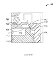
本明細書に記載の例示的流体調整器を説明する前に、既知の流体調整器100の簡単な説明が、図1A及び1Bに提供されている。図1A及び1Bを参照すると、例示的流体調整器100は、入口106と出口108との間の流体通路を規定するボンネット104にネジ結合する弁本体102を含有する。負荷アセンブリ110がボンネット104内に配設され、これはダイアフラム112に負荷をもたらすよう調整可能であり、この負荷は、所望の流体出口圧に相当する。ダイアフラム112の周縁部114は、ダイアフラム112の第1の側116と弁本体102が通路120を介して出口108と流体連通する検知室118を規定するように、ボンネット104と弁本体102との間に締付けられるか又は捕捉される。更に、ダイアフラム112に支持を提供するために、流体調整器100は、ダイアフラム112の第2の側126の一部分に係合する、実質的にフラットか又は平面状の接触面124を有するバックアッププレート122を含有する。このダイアフラム112は、ダイアフラム112の感度を増大させるための複数の波形輪郭部又は隆起部128を有する金属ダイアフラムである。ポペット弁130が弁座134に対して移動し、入口106と出口108との間の流体の流れを調整するか又は絞る。付勢要素136がポ
ペット弁130を弁座134に向かって偏倚させる。ポペット弁130はまた、ダイアフラム112とバックアッププレート122に係合するための幹状部138も含有する。
Prior to describing the exemplary fluid regulator described herein, a brief description of a known
稼働時に、出口108における流体圧が、ダイアフラム112の第1の側116に力をもたらし、その力が負荷アセンブリ110によってダイアフラム112の第2の側126にもたらされる力を超えるか又はそれに等しい場合、ダイアフラム112とバックアッププレート122は、幹状部138から離れる。その結果、ポペット弁130は弁座134に密封状態で係合し、入口106と出口108との間の流体流を制限する。ダイアフラム112の第1の側116にもたらされる力が、負荷アセンブリ110によってダイアフラム112の第2の側126にもたらされる力未満であるように、出口108における流体圧が減少する場合、ダイアフラム112は撓むか又は弁本体102に向かって移動し、ポペット弁幹状部138に係合し、このことが、ポペット弁130を弁座134から離れさせて、入口106と出口108との間の流体流をもたらす。加圧された流体は、ダイアフラム112の第1の側116及び第2の側126への力が釣り合うまで、入口106と出口108との間で流れる。
In operation, if the fluid pressure at the
図1Bに最も明確に示されるように、ダイアフラム112の周縁部114が、挟み込み点又は領域140で、ボンネット104と弁本体102との間で締付けられている。かかる締付接続は、稼働時にダイアフラム112が撓み又は屈曲する場合、これが挟み込み点140に直隣接する領域又は点142で比較的高い応力集中を発生するために、不利である。言い換えると、ダイアフラム112の領域142は、比較的高い応力集中を受けると同時に、屈曲するか又は撓み(すなわち、稼働時に移動し)、このことが稼働時に領域142を破断させ又は疲労を生じさせる場合がある。結果として、高度に集中された又は局在化した応力はダイアフラム112のサイクル寿命又は疲労寿命を低減し又は制限し得る。
As most clearly shown in FIG. 1B, the
加えて、示されてはいないが、一部の既知の例では、ダイアフラム112が弁座134に対して移動する場合、バックアッププレート122の平面状の接触面124は、ダイアフラム112の波形輪郭部128に係合する。特に、バックアッププレート122の接触面124は実質的にフラットであるために、接触面124は、ダイアフラム112の波形輪郭部128のピーク部144を介してダイアフラム112と係合する。したがって、バックアッププレート122は、比較的小さな接触面積で波形輪郭部128のピーク部に係合する。その結果、バックアッププレート122は、ピーク部144を介してダイアフラム112上に付与される増大した又は局在化した応力集中を生じさせ得る。上述したように、かかる局在化した応力は、ダイアフラム112を破断させるか又は疲労を生じさせる可能性があり、これによって、ダイアフラム112のサイクル寿命又は疲労寿命を低減させ、メンテナンス費用を増大させる。
In addition, although not shown, in some known examples, when the
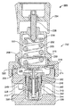
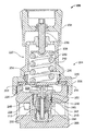
図2A及び2Bは、本明細書に記載の例示的流体調整器200を図示する。図2Aは、閉位置202での例示的流体調整器200を図示し、図2Bは、開位置204での例示的流体調整器200を図示する。
2A and 2B illustrate an
図2A及び2Bを参照すると、例示的流体調整器200は、下部本体部分又は弁本体208に結合した(例えば、ネジ結合した)上部本体部分又はボンネット206を有する調整器本体を含有する。弁本体208は、流体調整器200の入口210と出口212との間に流体流経路を形成する。ダイアフラム214は、ダイアフラム214の第1の側216とボンネット206が、負荷アセンブリ220を受け取るための負荷室218を規定するように、弁本体208とボンネット206との間で捕捉されている。ダイアフラム214の第2の側222と弁本体208の内側表面224は、検知室226を規定する。検知室226は、通路228を介して出口212に流動的に結合され、出口212において流
体の圧力を検知する。図示された例では、ダイアフラム214は、例えば、ステンレス鋼から構成される金属ダイアフラムである。
With reference to FIGS. 2A and 2B, an
負荷アセンブリ220は、ダイアフラムプレート又はバックアッププレート230を介してダイアフラム214に機能的に接続され、ダイアフラム214に基準力又は負荷(例えば、事前設定された力)をもたらす。この例では、負荷アセンブリ220は、バックアッププレート230を介してダイアフラム214に負荷を提供する負荷室218内に配設された付勢要素232(例えば、バネ)を含有する。バネ調整器234は、付勢要素232がダイアフラム214の第1の側216上に及ぼす事前設定された力又は負荷の量を調整する(例えば、増加又は減少させる)。示すように、バネ調整器234は、ボンネット206にネジ結合され、かつ調整可能なバネ座238に係合するネジ236にキー締めされた制御ノブを含有する。制御ノブの第1の方向(例えば、時計回り方向)での回転又は第2の方向(例えば、反時計回り方向)での回転は、付勢要素232の圧縮の量を変更し(例えば、付勢要素232を圧縮するか又は圧縮解除する)、したがって、ダイアフラム214の第1の側216に及ぼされる負荷の量を変更する。
The
弁装置又は弁カートリッジアセンブリ240が、入口210に流動的に結合された入口室244を規定する弁本体208の内腔242内に配設されている。弁装置240は、流体調整器200が閉位置202にある場合、入口210と出口212との間の流体流を制限するよう弁座248に向かって移動するポペット弁246を含有する。流体調整器200が開位置204にある場合、ポペット弁246が弁座248から離れて、入口210と出口212との間の流体の流れをもたらす。付勢要素250はポペット弁246を弁座248に向かって偏倚させる。シール252(例えば、O−リング)が弁装置240と流体調整器200の弁本体208問の間に配設され、検知室226と入口室244との間の密封をもたらす。
A valve device or
稼働時に、例示的流体調整器200は、例えば入口210を介して比較的高圧力の流体(例:気体)をもたらす上流側圧力供給源に流動的に結合し、並びに例えば出口212を介して低圧下流側装置又はシステムに流動的に結合する。流体調整器200は、流動調整器200を通過する流体の出口圧を、調整可能な負荷アセンブリ220によってもたらされる事前設定された負荷に相当する所望の圧力に調整する。
In operation, the
所望の出口圧を達成するために、制御ノブが回転され(例えば、時計回り又は反時計回り方向で)、ダイアフラム214の第1の側216に付勢要素232によって及ぼされる負荷を増加させるか又は減少させる。付勢要素232によってもたらされる負荷は、所望の出口圧に相当するよう調整される。基準圧力設定を使用して、検知室226は、通路228を介して出口212における加圧された流体の圧力を検知し、これが検知室226内の圧力変化に応答して、ダイアフラム214を移動させる。
In order to achieve the desired outlet pressure, the control knob is rotated (eg, in a clockwise or counterclockwise direction) to increase the load exerted by the biasing
例えば、流体が入口210と出口212との間を流れると同時に、出口212における流体の圧力が増大する。検知室226内の加圧された流体の圧力が増大すると同時に、流体の圧力はダイアフラム214の第2の側222に力を及ぼし、ダイアフラム214と付勢要素232を弁本体208から離れて往復直線運動で移動させる。今度は、弁装置240の付勢要素250が、ポペット弁246を弁座248に向かって移動させて、入口210と出口212との間の流体流を制限する。ダイアフラム214の第2の側222上に力を及ぼす検知室226内の流体の、ダイアフラム214の第1の側216上に負荷アセンブリ220によって及ぼされる基準圧力又は力を超える圧力が、バックアッププレート230を弁本体208から離れさせて、図2Aに示すように、ポペット弁246を弁座248に密封状態で係合させて、流体調整器200を通過する流体流を制限し又は抑制する。
For example, as the fluid flows between the
検知室226内の加圧された流体の圧力が、ダイアフラム214の第1の側216に付勢要素232によって及ぼされる基準圧力又は力未満である場合、ダイアフラム214は、弁本体208に向かって移動し、屈曲し又は撓む。今度は、バックアッププレート230がポペット弁246の幹状部254に係合し、ポペット弁246を弁座248から離し、入口210と出口212との間の流体流をもたらすか又は増大させる。ダイアフラム214の全体にわたる圧力差が実質的にゼロに近い場合(すなわち、検知室226内の流体の圧力が負荷アセンブリ220によってもたらされる負荷に実質的に等しい力を発生する圧力に調整されている場合)、ポペット弁246は、弁座248に向かって移動し、入口210と出口212との間の流体流を抑制し又は制限する。
If the pressure of the pressurized fluid in the
図2A及び2Bで示すような稼働時に、ダイアフラム214は、ポペット弁246を閉位置202に向かって移動させる図2Aに示す第1の位置と、ポペット弁246を開位置204に向かって移動させる図2Bに示す第2の位置との間で移動し、撓み、又は屈曲して移動する。
During operation as shown in FIGS. 2A and 2B, the
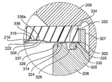
図3A及び3Bは、図2A及び2Bの流体調整器200の拡大された部分を図示する。図3A及び3Bに最も明確に示すように、図示された例のダイアフラム214は、周縁部302と、中央部分304と、周縁部302と中央部分304との間の中間の可動性又は可撓性部分306とを含有する。周縁部302と中央部分304のそれぞれは、実質的に平面状の又はフラットな表面を有する。中間部分306は、ダイアフラム214が図2A及び2Bに示す第1の位置と第2の位置との間を移動する場合、撓み又は屈曲する複数の波形輪郭部又は隆起部308を有する。特に、中間部分306の輪郭部308のそれぞれは、連続する滑らかな曲線若しくは波形輪郭部又は隆起部308を形成する凸状部又は湾曲面310並びに凹状部又は湾曲面312を含有する。凸状部310及び/又は凹状部312のそれぞれは、実質的に同様な曲率半径を有してもよく、又は異なる曲率半径を有してもよい。例えば、輪郭部308aの第1の凸状部分310a及び/又は凹状部312aは、第1の曲率半径を有してもよく、輪郭部308bの第2の凸状部分310b及び/又は凹状部312bは、第1の曲率半径とは異なる第2の曲率半径を有してもよい。輪郭部308は、ダイアフラム214の感度を著しく増大させて、流体調整器200がよりコンパクトな寸法外形を有することを可能にする。ダイアフラム214は、例えば、ステンレス鋼などの金属材料から構成される。
3A and 3B illustrate an enlarged portion of the
ダイアフラム214の中間部分306上の応力集中を低減するために、流体調整器200は、検知室226に隣接する1つ以上のダイアフラム境界面又は支持面314、316及び/又は318を含有する。ダイアフラム境界面314、316及び/又は318のそれぞれは、ダイアフラム214のサイクル寿命又は疲労寿命を増大させる。特に、ダイアフラム境界面314、316及び/又は318のそれぞれは、ダイアフラム214と係合する場合の接触面積を実質的に増大させて、これによって、稼働時のダイアフラム214への応力集中を低減する。いくつかの例においては、流体調整器は、ダイアフラム境界面314、316又は318のうちの1つだけを用いる。しかしながら、境界面314、316及び318のいずれの組み合わせが用いられてもよい。
To reduce stress concentrations on the
図示された例において、ダイアフラム境界面314は、一体型ピース又は構造として、弁本体208と共に一体的に形成される。示すように、弁本体208は環状壁320を有し、これは内側表面224に隣接する環状壁320の上縁部又は部分322においてダイアフラム境界面314を規定する。弁本体208のダイアフラム境界面314は、ダイアフラム214の周縁部302を保持し、受け取り又は周縁部に係合するリング状座部又はダイアフラム取付台324を含有する。リング状座部324は、流体調整器200の稼働時に移動する又は撓むダイアフラム214の周縁部302及び/又は中間部306の一部分を支持するための、ダイアフラム取付台324に隣接する丸くなった縁部又は円弧縁部
326aを有する湾曲した、勾配がある又は傾斜面326を含有する。
In the illustrated example, the
ダイアフラム取付台324は、ダイアフラム214の周縁部302を受け取り又はこれに係合するための実質的に平面状又はフラットな表面を有する。示すように、ダイアフラム取付台324は、内側表面224に実質的に垂直である。傾斜部分326及び円弧縁部326aは、ダイアフラム取付台324と内側表面224との間に位置する。傾斜部分326は、均一の曲率半径を有する湾曲面、又は連続する傾斜部分を形成する異なる曲率半径を有する複数の湾曲面を有してもよい。傾斜部分326及び/又はダイアフラム取付台324は、ダイアフラム214が流体調整器200に結合する場合、実質的に気密な金属同士の密封状態をもたらす。いくつかの例では、金属同士の密封を容易にするために、弁本体208の段が付けられた環状壁327に隣接するダイアフラム取付台324の肩部325が、傾斜部分326に対して(例えば、図3Aの方向で傾斜部分326よりも低く)オフセット(例えば、0.015インチのオフセット)される。このようにして、ボンネット206が弁本体208に結合する場合、弁本体208の傾斜部分326に加えられるトルクが、傾斜面326の少なくとも一部分を変形させるかフラットにさせて、実質的に気密な金属同士の密封状態をもたらす。弁本体208は、ダイアフラム214の材料よりも比較的柔軟な材料から構成され得る。
稼働時に、傾斜部分326は、周縁部302に隣接するダイアフラム214の一部分が、傾斜部分326に沿って撓むか又は転がることを可能にする。例えば、周縁部302に隣接するダイアフラム214の中間部分306が、弁本体208に向かって移動し又は撓んで第2の位置(例えば、図2Bの位置)になる場合、周縁部302に隣接する中間部分306の第2の側222は、弁本体208の傾斜部分326に係合する。傾斜部分326は、中間部分306と弁本体208との間の接触面積を増大させて、中間部分306に付与された応力を、傾斜部分326に係合する又はその回りを転がるダイアフラム214の領域又は部分にわたってより均一に分散させるか又は低減させる。言い換えると、傾斜面又は湾曲面326は、周縁部302に隣接する中間部分306が著しく低減された応力集中を受けると同時に、撓み又は屈曲することを可能にする。
In operation, the ramped
例えば、図1A及び1Bの既知の流体調整器100とは対照的に、ダイアフラム境界面314又は弁本体208の傾斜部分326は、弁本体208とボンネット206との間の挟み込み点又は領域(例えば、図1A及び1Bの挟み込み点140)を著しく低減又は排除する。傾斜部分326は、周縁部302に隣接するダイアフラム214のより大きな部分又は領域が、図1Bの挟み込み点140に比較してより小さい捩り剛性と曲げ剛性で傾斜部分326の回りで転がり又は撓むことを可能にし、これによって、周縁部302に隣接するダイアフラム214のより大きな接触面積全体に応力を分散させることで、応力の集中を低減させる。換言すると、ダイアフラム112が挟み込み点140の回りで屈曲する場合に、図1A及び1Bの流体調整器100のダイアフラム112に付与される圧縮応力及び引張応力に比較して、ダイアフラム214の第2の側222に付与されるより小さい圧縮応力で、かつダイアフラム214の第1の側216に付与されるより小さい引張応力で、ダイアフラム214は傾斜部分326の回りで屈曲する。したがって、傾斜部分326は、弁本体208と中間部分306との間の接触面積を増大させて、これによって、周縁部302に隣接するダイアフラム214の中間部分306にわたる応力集中を低減する。傾斜部分326は、機械加工、鋳造又は任意の他の好適な製造プロセス(複数可)を介して形成され得る。示すように、実質的に気密な金属同士の密封が必要とされない場合、冗長密封をもたらすために及び/又は組立を容易にするために、ダイアフラム境界面314又はダイアフラム取付台324は、必要に応じて、弁本体208とボンネット206との間の密封(例えば冗長密封)をもたらすために、O−リング330を受け取るための凹部328を有してもよい。O−リング330は、金属同士の密封をもたらすのに必要とされるトルクに比べて、密封をもたらすためにより小さいトルクを必要とするために、組
立を容易にすることができる。
For example, in contrast to the known
図示された例において、流体調整器200は、ボンネット206と弁本体208との間でダイアフラム214を保持し又は締付けるために、リング状クランプ又は保持部材332を用いる。更に、保持部材332は、周縁部302に隣接する中間部分306に支持をもたらすダイアフラム境界面316を規定する。ダイアフラム境界面316は、ダイアフラム締付部分334と、ダイアフラム締付部分334に隣接するダイアフラム支持部分336とを含有する。
In the illustrated example, the
示すように、ダイアフラム214の周縁部302は、ダイアフラム締付部分334と弁本体208のダイアフラム取付台324との間で締付けられる。特に、ボンネット206及び弁本体208の組立て中に、トルクがボンネット206に加えられる場合、ダイアフラム214と弁本体208との間の金属同士の密封状態をもたらすよう補助するために、弁本体208がボンネット206に結合されるときに、保持部材332のダイアフラム締付部分334は、ダイアフラム214の周縁部302に負荷を移行させる。弁本体208に結合させる場合、ボンネット206は、保持部材332を介してダイアフラム214の周縁部302に圧縮負荷をもたらす。この例においては、保持部材332は、保持部材332、弁本体208、ボンネット206及びダイアフラム214の間の金属同士の接触をもたらすために、例えば、ステンレス鋼などの金属材料から構成される。
As shown, the
ダイアフラム境界面316のダイアフラム支持部分336は、ダイアフラム締付部分334から離れて、かつ周縁部302から検知室226に向かって内向きに突出する湾曲した又は弓形の表面336aを含有する。例えば、ダイアフラム支持部分336は、弁本体208の環状壁320の内側表面224又は上縁部302を超えて又はこれらを通過して延在する。かかる伸長部は、ダイアフラム214を支持するために、ダイアフラム支持部分336が周縁部302に隣接する中間部分306の第1の側216に係合することを可能にする。特に、ダイアフラム支持部分336は、ダイアフラム214の第1の側216の輪郭部308の凹状部310の少なくとも一部分337に係合する。したがって、保持部材332又はダイアフラム境界面316並びに傾斜部分326又はダイアフラム境界面314は、ダイアフラム214の対向面又は対向側216及び222にそれぞれ係合する。更に、図3A及び3Bに示すように、湾曲面336aは、周縁部分302に隣接する中間部分306の形状又はプロファイルと実質的に同様な形状又はプロファイルを有することで、湾曲面は、周縁部302に隣接する中間部分306に結合可能に係合する。
The
図4は、図3A及び3Bの保持部材332の断面を示す。図4をまた参照すると、保持部材332は、外径404と内径406を有するリング状クランプ402である。例えば、外径404は、約64.5ミリメートルであってもよく、内径406は、約44.5ミリメートルである。この例では、ダイアフラム締付部分334は長さ408を有し、ダイアフラム支持部分336は、長さ410を有する。例えば、長さ408は約5.25ミリメートルであり、長さ410は約4.75ミリメートルである。しかしながら、他の長さ及び/又は直径が、特定の用途の必要性に適するよう使用されてもよい。
FIG. 4 shows a cross section of the retaining
更に、図示された例において、ダイアフラム支持部分336の湾曲面は、周縁部302に隣接する中間部分306の曲率半径と実質的に同様である曲率半径412を有する。したがって、湾曲面336aは、周縁部302に隣接する中間部分306の湾曲したプロファイルに相補的である湾曲したプロファイルを有し得る。例えば、湾曲面の半径412は約8.5ミリメートルである。しかしながら、曲率半径は、特定の用途の必要性に適するよう必要に応じて変更されてもよい。
Further, in the illustrated example, the curved surface of
このように、湾曲面336aは、例えば、図1A及び1Bの流体調整器100と比較し
て、比較的大きな接触面積で、周縁部302に隣接する中間部分306に係合し、これによって、稼働時にダイアフラム214が第1の位置と第2の位置との間を移動する場合、周縁部302に隣接する中間部分306における応力集中を低減する。例えば、ダイアフラム112が挟み込み点140の回りで屈曲する場合の図1A及び1Bの流体調整器100のダイアフラム112に付与される圧縮応力及び引張応力と比較して、保持部材332は、ダイアフラム214の第1の側216上の高圧縮応力集中を著しく軽減し、並びに検知室226を介してダイアフラム214の第2の側222に圧力又は力が加えられる場合のダイアフラム214の第2の側222上の高引張応力集中を著しく低減する。その結果、ダイアフラム境界面316は、ダイアフラム214のサイクル寿命又は疲労寿命を著しく改善する。他の例において、湾曲面336aは、ダイアフラム214の中間部分306の曲率半径とは異なる曲率半径を有してもよい。
Thus, the
図示されていないが、保持部材332及び/又はダイアフラム境界面316若しくはダイアフラム支持部分336は、一体型ピース又は構造として、ボンネット206と一体的に形成されてもよい。換言すると、ダイアフラム支持部分336は、ボンネット206の内側表面338から延在してもよく、保持部材332が省かれてもよい。
Although not shown, the retaining
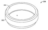
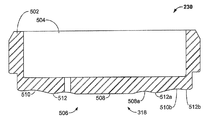
図5A及び5Bは、流体調整器200のバックアッププレート230を図示する。図2A、2B、3A、5A及び5Bを参照すると、バックアッププレート230は、ダイアフラム214に係合しかつこれを支持するためのダイアフラム境界面又は支持表面318を含有する。バックアッププレート230は、負荷アセンブリ220の付勢要素232を受け取るための空洞部504を有する円筒状本体部分502を有する。示すように、ダイアフラム境界面318は、ダイアフラム214とバックアッププレート230との間の接触面積を増大させるための湾曲した支持表面又は面506を含有する。図示された例では、バックアッププレート230のダイアフラム境界面318は、ダイアフラム214の中央部分304(図3A)に係合するための実質的に平面状又はフラットな係合表面508を含有する。
5A and 5B illustrate the
湾曲した支持表面又は面506は、バックアッププレート320に係合するダイアフラム214の部分のプロファイルに相補的である湾曲したプロファイルを有する。このように、湾曲した支持表面506は、ダイアフラム214の中間部分306又は輪郭部308に係合するための比較的大きな接触面積をもたらす。図示された例において、湾曲した支持表面506は、滑らかな連続する波形の湾曲した支持表面をもたらすために、凸状湾曲部分512に隣接する凹状湾曲部分510を含有する。言い換えれば、湾曲した支持部分506の断面形状は、ダイアフラム214の輪郭部308の断面形状と実質的に同様である。例えば、湾曲した支持表面506の凹状湾曲部分510は、ダイアフラム214の輪郭部308の凸状部分310の曲率半径と実質的に同様である曲率半径を有する。同様に、湾曲した支持表面506の凸状湾曲部分512は、ダイアフラム214の輪郭部308の凹状部分312の曲率半径と実質的に同様である曲率半径を有する。
The curved support surface or
更に、湾曲した支持表面506の第1の凹状湾曲部分510aは、湾曲した支持表面506の第2の凹状湾曲部分510bの曲率半径とは異なる、又はこれと同様である曲率半径を有してもよい。例えば、凹状湾曲部分510の曲率半径は、6.0と8.0ミリメートルとの間の範囲であり得る。同様に、湾曲した支持表面506の第1の凸状湾曲部分512aは、第2の凸状湾曲部分512bの曲率半径とは異なる、又はこれと同様である曲率半径を有してもよい。例えば、凸状湾曲部分512の曲率半径は、8.0と10.0ミリメートルとの間の範囲であり得る。
Further, the first concave curved portion 510a of the
したがって、図1Aのバックアッププレート122とは対照的に、バックアッププレート230のダイアフラム境界面318は、ダイアフラム214の中間部分306に実質的
に結合可能に係合し、バックアッププレート230とダイアフラム214との間に増大した接触面積をもたらし、これが検知室226内の圧力変化に応答して移動するダイアフラム214の中間部分306に付与される応力の量に影響を与える(例えば、低減する)。この例では、ダイアフラム支持表面506は、ダイアフラム214上の局在化した応力集中を低減する。例えば、ダイアフラム214が、図2Aに示される位置と図2Bで示される位置との間を移動する場合、バックアッププレート230は比較的大きな接触面積で、ダイアフラム214の中間部分306に係合する(結合可能に係合する)。結果的に、局在化した応力集中における減少が、ダイアフラム214のサイクル寿命又は疲労寿命を著しく改善し、又は著しく増大させる。
Thus, in contrast to the
他の例において、バックアッププレート230のダイアフラム境界面318は、ダイアフラム214の形状、プロファイル又は断面とは異なる形状、プロファイル又は断面を含む。例えば、湾曲した支持表面506とダイアフラム214の輪郭部308との間の曲率半径は、ダイアフラム214がバックアッププレート230とは結合可能に係合しないが、それにもかかわらず図1A及び1Bのバックアッププレートに対して増大した接触面積をもたらすように異なってもよい。
In other examples, the
したがって、本明細書に記載の流体調整器200は、ダイアフラム境界面314、316及び/又は318を含有し、これらは、ダイアフラム境界面314、316及び/又は318とダイアフラム214との間の接触面積を増大させるために、ダイアフラム214の形状又はプロファイルと実質的に同様である形状又はプロファイルを有するよう構成され得る。例えば、ダイアフラム境界面314、316及び/又は318のそれぞれは、稼働時に移動するダイアフラム214の一部分に付与される応力集中を低減するために、ダイアフラム214によって係合される場合、接触面積を増大させるための対応の湾曲面又は部分を含有することができる。いくつかの例では、ダイアフラム境界面314、316及び/又は318の支持表面は、ダイアフラム214の断面形状又はプロファイルと実質的に同様である断面形状又はプロファイルを有することで、ダイアフラム境界面314、316及び/又は318は、ダイアフラム214の少なくとも一部分と結合可能に係合する。結果的に、ダイアフラム境界面314、316及び/又は318は、ダイアフラム214に付与される応力集中を低減し、これによって、ダイアフラム214のサイクル寿命又は疲労寿命を増大させる。例えば、ダイアフラム214のサイクル寿命は約85,000サイクルであり、一方図1A及び1Bのダイアフラム112の寿命サイクルは、約10,000サイクルである。いくつかの例において、流体調整器200は、ダイアフラム境界面314、316及び/又は318のうちの1つだけで実現可能であるか、又は境界面314、316及び318の任意の組み合わせで実現可能である。
Accordingly, the
特定の例示的方法、装置及び製造の物品が本明細書で説明されてきたが、本特許でカバーされる範囲は、これらに限定されるものではない。反対に、本特許は、文字通り又は等価物の原則の下に、添付された特許請求の範囲の範囲内に適正に収まる全ての方法、装置及び製造の物品をカバーするものである。 Although certain exemplary methods, apparatus, and articles of manufacture have been described herein, the scope covered by this patent is not limited thereto. On the contrary, this patent covers all methods, devices and articles of manufacture that fall within the scope of the appended claims, literally or under the principle of equivalents.
Claims (20)
入口と出口との間の流体流通路と、
前記流体流通路の一部分を規定する検知室と、
前記検知室内の圧力を検知するためのダイアフラムと、
前記検知室に隣接するダイアフラム境界面と、を含む流体調整器であり、前記ダイアフラム境界面が、前記検知室内の圧力変化に応答して移動する前記ダイアフラムの一部分に接触するための湾曲面を有し、前記湾曲面が、前記流体調整器の稼働時に前記ダイアフラムの前記部分に付与される応力の量に影響を与える、流体調整器。 A fluid regulator,
A fluid flow path between the inlet and the outlet;
A detection chamber defining a portion of the fluid flow path;
A diaphragm for detecting the pressure in the detection chamber;
A diaphragm boundary surface adjacent to the detection chamber, the diaphragm boundary surface having a curved surface for contacting a part of the diaphragm moving in response to a pressure change in the detection chamber. And the curved surface affects the amount of stress applied to the portion of the diaphragm during operation of the fluid regulator.
ダイアフラムの可動部分を支持するために、ボンネットと弁本体との間に配設されたダイアフラム支持体を含み、前記ダイアフラム支持体が、稼働時に前記ダイアフラム支持体と前記ダイアフラムの前記可動部分との間の接触面積を増大させるために、前記ダイアフラムの前記可動部分の面の湾曲面に実質的に相補的である湾曲面を有する、流体調整器。 A fluid regulator,
A diaphragm support disposed between the bonnet and the valve body to support the movable part of the diaphragm, the diaphragm support being in operation between the diaphragm support and the movable part of the diaphragm; A fluid regulator having a curved surface that is substantially complementary to a curved surface of the surface of the movable portion of the diaphragm to increase the contact area of the diaphragm.
流体流通路を通過する流体流を調整するための手段であり、金属材料から構成されるダイアフラムを含む流体流を調整するための手段と、
稼働時に前記ダイアフラムの可動部分に付与される応力集中を低減させるための手段と、を含む流体調整器。 A fluid regulator,
Means for adjusting fluid flow through the fluid flow passage, and means for adjusting fluid flow including a diaphragm composed of a metallic material;
Means for reducing stress concentration applied to the movable part of the diaphragm during operation.
Applications Claiming Priority (2)
| Application Number | Priority Date | Filing Date | Title |
|---|---|---|---|
| US13/052,475 US9874883B2 (en) | 2009-07-02 | 2011-03-21 | Diaphragm interface apparatus to improve a cycle life of a diaphragm |
| US13/052,475 | 2011-03-21 |
Related Parent Applications (1)
| Application Number | Title | Priority Date | Filing Date |
|---|---|---|---|
| JP2014501078A Division JP2014509034A (en) | 2011-03-21 | 2012-02-22 | Diaphragm interface device for improving diaphragm cycle life. |
Publications (2)
| Publication Number | Publication Date |
|---|---|
| JP2017201329A true JP2017201329A (en) | 2017-11-09 |
| JP6526751B2 JP6526751B2 (en) | 2019-06-05 |
Family
ID=45888470
Family Applications (2)
| Application Number | Title | Priority Date | Filing Date |
|---|---|---|---|
| JP2014501078A Pending JP2014509034A (en) | 2011-03-21 | 2012-02-22 | Diaphragm interface device for improving diaphragm cycle life. |
| JP2017139875A Active JP6526751B2 (en) | 2011-03-21 | 2017-07-19 | Diaphragm interface device for improving diaphragm cycle life |
Family Applications Before (1)
| Application Number | Title | Priority Date | Filing Date |
|---|---|---|---|
| JP2014501078A Pending JP2014509034A (en) | 2011-03-21 | 2012-02-22 | Diaphragm interface device for improving diaphragm cycle life. |
Country Status (12)
| Country | Link |
|---|---|
| US (1) | US9874883B2 (en) |
| EP (1) | EP2689310B1 (en) |
| JP (2) | JP2014509034A (en) |
| KR (1) | KR20140020283A (en) |
| CN (1) | CN202418758U (en) |
| AU (1) | AU2012249193B2 (en) |
| BR (1) | BR112013024097A2 (en) |
| CA (1) | CA2830198C (en) |
| MX (1) | MX354784B (en) |
| NO (1) | NO20131311A1 (en) |
| RU (1) | RU2627022C2 (en) |
| WO (1) | WO2012148532A1 (en) |
Families Citing this family (9)
| Publication number | Priority date | Publication date | Assignee | Title |
|---|---|---|---|---|
| US20110174398A1 (en) * | 2009-07-02 | 2011-07-21 | Jason David Clifford | Valve apparatus to prevent contamination of fluid in a fluid regulator |
| US9371925B2 (en) * | 2013-07-30 | 2016-06-21 | Tescom Corporation | Fluid regulators having corrugated diaphragms |
| US9441745B2 (en) | 2014-03-03 | 2016-09-13 | Emerson Process Management Regulator Technologies, Inc. | Apparatus to interface with a corrugated diaphragm |
| CN104006178B (en) * | 2014-06-09 | 2016-09-07 | 宁波新佳行自动化工业有限公司 | Metal pressure regulator valve |
| MX387570B (en) * | 2015-10-20 | 2025-03-18 | Emerson Process Man Regulator Technologies Inc | PRESSURE REGULATING DEVICE THAT HAS A VARIABLE TRAVEL STOP. |
| EP3187758B1 (en) * | 2016-01-04 | 2019-04-03 | Danfoss A/S | Capsule for a valve and valve |
| CN116056801B (en) * | 2020-08-07 | 2026-02-13 | 固瑞克明尼苏达有限公司 | Back pressure regulator |
| US11885419B1 (en) * | 2022-07-08 | 2024-01-30 | Ultra Flow Holdings, LLC | Pressure regulating valve |
| LU504900B1 (en) | 2023-08-11 | 2025-02-11 | Rotarex S A | Pressure reducer with seat and shutter inserted from a bottom face |
Citations (7)
| Publication number | Priority date | Publication date | Assignee | Title |
|---|---|---|---|---|
| JPS457009Y1 (en) * | 1964-11-21 | 1970-04-06 | ||
| JPS5114730B1 (en) * | 1970-07-25 | 1976-05-12 | ||
| JPS565877U (en) * | 1979-06-26 | 1981-01-19 | ||
| JP2006153132A (en) * | 2004-11-29 | 2006-06-15 | Ckd Corp | Diaphragm valve |
| US20060169328A1 (en) * | 2004-12-20 | 2006-08-03 | Samsung Electronics Co., Ltd. | Regulator and gas supply method using the same |
| JP2006260385A (en) * | 2005-03-18 | 2006-09-28 | Osaka Gas Co Ltd | Pressure governor and processing method |
| US20110000553A1 (en) * | 2009-07-02 | 2011-01-06 | Tescom Corporation | Balanced Valve Cartridge |
Family Cites Families (81)
| Publication number | Priority date | Publication date | Assignee | Title |
|---|---|---|---|---|
| US466275A (en) * | 1891-12-29 | fasoldt | ||
| US330263A (en) | 1885-11-10 | Gas-regulator | ||
| US1045791A (en) | 1912-08-01 | 1912-11-26 | Stuart W Cramer | Flexible metallic diaphragm. |
| US1286397A (en) | 1917-12-26 | 1918-12-03 | Frederich Marggraff | Expansion-valve for refrigerating apparatus. |
| US1452252A (en) | 1922-05-12 | 1923-04-17 | Muller Joseph | Automatic safety expansion valve |
| US1543264A (en) | 1923-09-21 | 1925-06-23 | Porter A Morgan | Vacuum-controlled regulator |
| GB335044A (en) | 1928-10-27 | 1930-09-18 | Alfred Curt Becker | Improvements relating to gas pressure regulators |
| US1891547A (en) * | 1930-07-02 | 1932-12-20 | William F Krichbaum | Auxiliary operated governing valve |
| GB451379A (en) | 1935-05-28 | 1936-08-05 | Henry Noel Negretti | Improvements in or relating to diaphragms for pressure gauges and the like |
| US2082227A (en) * | 1935-12-14 | 1937-06-01 | Victor Welding Equipment Co | Gas pressure regulator |
| GB521273A (en) | 1938-11-10 | 1940-05-16 | Smith & Sons Ltd S | Improvements in or relating to pressure-sensitive capsules |
| US2348388A (en) * | 1940-12-06 | 1944-05-09 | Alexander F Jenkins | Fluid pressure regulator |
| US2667127A (en) | 1946-07-20 | 1954-01-26 | Sulzer Ag | Motor-driven pump |
| US2612728A (en) | 1946-10-02 | 1952-10-07 | Union Carbide & Carbon Corp | Fluid pressure regulator |
| US2521637A (en) | 1948-03-17 | 1950-09-05 | Lack Sydney Walter | Reducing valve mechanism |
| US2664674A (en) * | 1948-04-27 | 1954-01-05 | Rockwell Mfg Co | Fluid regulator valve |
| US2707966A (en) * | 1950-05-25 | 1955-05-10 | John F Taplin | Pressure regulator valve |
| US2806481A (en) * | 1953-04-08 | 1957-09-17 | Norgren Co C A | Pilot controlled pressure regulator |
| US2918081A (en) * | 1954-02-09 | 1959-12-22 | Air Prod Inc | Fluid pressure control device |
| US2894526A (en) * | 1954-07-26 | 1959-07-14 | United Aircraft Prod | Pressure regulating valve |
| GB834574A (en) | 1956-07-06 | 1960-05-11 | Int Basic Economy Corp | Valve |
| US2942624A (en) | 1956-11-14 | 1960-06-28 | Penn Controls | Pressure responsive actuator |
| US3120377A (en) * | 1960-01-07 | 1964-02-04 | Emulsol Egg Products Corp | Apparatus for producing dressing |
| US3113756A (en) * | 1961-05-08 | 1963-12-10 | Lincoln Tool And Machine Co In | Regulator |
| US3434395A (en) | 1964-10-26 | 1969-03-25 | Holley Carburetor Co | Pressure responsive mechanism |
| US3387622A (en) * | 1965-09-22 | 1968-06-11 | Flair Mfg Corp | Valve |
| GB1210065A (en) * | 1967-03-31 | 1970-10-28 | I V Pressure Controllers Ltd | Improvements in or relating to diaphragms |
| DE1808567B2 (en) | 1968-11-13 | 1972-03-23 | Max Planck Gesellschaft zur Forderung der Wissenschaften e V , 3400 Got tingen | VACUUM CONTROL VALVE AND OPERATING PROCEDURE FOR IT |
| US3586037A (en) * | 1969-05-26 | 1971-06-22 | Victor Equipment Co | Single stage, compensated pressure regulator |
| US3667722A (en) * | 1970-10-22 | 1972-06-06 | Ite Imperial Corp | Proportional valve |
| US3819286A (en) | 1971-11-01 | 1974-06-25 | Saip Spa | Hydraulic tightening-up device for very high stresses |
| US4055198A (en) * | 1974-08-15 | 1977-10-25 | Tannetics, Inc. | Excess pressure relieving valve |
| US4196744A (en) | 1976-09-21 | 1980-04-08 | Eaton Corporation | Exhaust gas recirculation control |
| US4457329A (en) * | 1981-12-04 | 1984-07-03 | Air Products And Chemicals, Inc. | Safety pressure regulator |
| ES519218A0 (en) | 1982-01-27 | 1983-12-16 | Eltek Srl | THERMOELECTRIC VALVE OF ONE OR MORE WAYS. |
| US4471802A (en) * | 1983-04-12 | 1984-09-18 | Victor Equipment Company, Inc. | Pressure regulator assembly with improved cartridge |
| US4543832A (en) | 1983-09-30 | 1985-10-01 | Transducers, Inc. | Overload protected pressure transducer |
| US4624442A (en) * | 1985-01-23 | 1986-11-25 | Duffy John W | Control regulator having a rolling diaphragm |
| JPH0426889Y2 (en) * | 1985-04-02 | 1992-06-29 | ||
| US4741252A (en) | 1986-09-24 | 1988-05-03 | Allied-Signal Inc. | Diaphragm of the rolling type having a membrane portion and a reinforcing portion |
| GB8819741D0 (en) | 1988-08-19 | 1988-09-21 | Hattersley Heaton Ltd | Seat for butterfly valve |
| US5292024A (en) * | 1992-05-19 | 1994-03-08 | Rehrig Pacific Company, Inc. | Plastic pail assembly for hazardous materials |
| US5449003A (en) * | 1992-12-28 | 1995-09-12 | Sugimura; Kazuo | Undulated container for undulated diaphragm and diaphragm device |
| US5443083A (en) * | 1993-02-11 | 1995-08-22 | Itt Corporation | Pressure-reducing regulator for compressed natural gas |
| US5335584A (en) | 1993-03-30 | 1994-08-09 | Baird Dayne E | Improved diaphragm |
| CA2125206C (en) | 1993-06-07 | 2000-07-25 | Yasuo Yamabe | Vacuum valve control device and vacuum valve |
| US5762314A (en) * | 1993-06-08 | 1998-06-09 | O.I. Corporation | Diaphragm valve for cryogenic applications |
| DE4430472A1 (en) | 1994-08-27 | 1996-02-29 | Bosch Gmbh Robert | Pressure control valve |
| CA2131108C (en) * | 1994-08-30 | 2005-06-07 | Stephen A. Carter | Two-stage pressure regulator |
| US5567130A (en) * | 1994-11-09 | 1996-10-22 | Graco Inc. | Reinforced cover configuration for a diaphragm pump |
| JP3291151B2 (en) | 1995-02-15 | 2002-06-10 | 株式会社フジキン | Diaphragm valve |
| JP2791546B2 (en) * | 1995-02-27 | 1998-08-27 | 株式会社ヨシタケ | Control valve with metal diaphragm |
| US5725007A (en) | 1995-07-07 | 1998-03-10 | Stubbs; William L. | Valve mechanism and method for making same |
| US5586569A (en) * | 1995-07-27 | 1996-12-24 | Parker-Hannifin Corporation | Pneumatic pressure regulator |
| US6003545A (en) * | 1996-07-16 | 1999-12-21 | Controls Corporation Of America | Gas flow control device for high purity, highly corrosive gas service |
| US5829477A (en) * | 1996-09-04 | 1998-11-03 | Taprite-Fassco Manufacturing, Inc. | Modular regulator |
| DE19650194C1 (en) * | 1996-12-04 | 1998-04-02 | Daimler Benz Ag | Fuel tank filling level limit device |
| JP3833323B2 (en) * | 1997-01-07 | 2006-10-11 | Smc株式会社 | Pressure reducing valve |
| JP3796006B2 (en) * | 1997-05-27 | 2006-07-12 | Smc株式会社 | Valve seal mechanism |
| US5904178A (en) * | 1997-06-20 | 1999-05-18 | Controls Corporation Of America | Gas filter for regulator valve, and improved regulator valve employing the filter |
| US5881997A (en) * | 1997-11-24 | 1999-03-16 | Fujikin Incorporated | Metal diaphragm type valve |
| US5950652A (en) * | 1998-02-11 | 1999-09-14 | Parker Hannifin Corporation | Load balanced pressure regulator and method and apparatus for delivering process gas for manufacturing semiconductor devices employing same |
| US6536466B1 (en) * | 1998-09-04 | 2003-03-25 | Wanner Engineering | Pressure regulator apparatus |
| US6394417B1 (en) * | 1998-10-09 | 2002-05-28 | Swagelok Co. | Sanitary diaphragm valve |
| US6276907B1 (en) | 1999-08-12 | 2001-08-21 | Wagner Spray Tech Corporation | Hydraulically driven diaphragm pump |
| US20050116427A1 (en) | 2003-11-25 | 2005-06-02 | Francis Seidel | Corrugated gasket core with profiled surface |
| DE202004006191U1 (en) | 2004-04-20 | 2004-08-19 | Radtke, Reinhard | Precision valve for control of liquids in e.g. surface treatment systems uses ribbed, resilient membrane as piston guide and acts as partition between high and low pressure zones, without control hysteresis |
| FR2878985B1 (en) | 2004-12-07 | 2007-04-20 | R G S A S Di Rosaria Galli & C | BALANCED PRESSURE REDUCER |
| US7926785B2 (en) | 2005-06-22 | 2011-04-19 | Wincek Christopher P | Valve diaphragm with a compression restraining ring, and valve including same |
| DE102006007363A1 (en) * | 2006-02-17 | 2007-08-23 | Robert Bosch Gmbh | Pilot operated pressure relief valve |
| US20090065073A1 (en) | 2007-09-11 | 2009-03-12 | Davis David B | Metal sealing disk having an elastomeric backing for use with fluid regulators |
| US20090071548A1 (en) * | 2007-09-14 | 2009-03-19 | Daryll Duane Patterson | Modular in-line fluid regulators |
| US8522809B2 (en) * | 2008-06-05 | 2013-09-03 | Illinois Tool Works Inc. | Gas regulator with venting bonnet |
| GB2464283B (en) | 2008-10-08 | 2012-09-19 | Bifold Fluidpower Ltd | Fluid flow control system and method |
| JP5366649B2 (en) * | 2009-05-15 | 2013-12-11 | トーステ株式会社 | Resin diaphragm type fluid control valve |
| US20110174398A1 (en) * | 2009-07-02 | 2011-07-21 | Jason David Clifford | Valve apparatus to prevent contamination of fluid in a fluid regulator |
| US8408418B2 (en) * | 2010-11-05 | 2013-04-02 | Michael D. Stolzman | Drum cover with center support |
| US20120241033A1 (en) * | 2011-03-21 | 2012-09-27 | Jason David Clifford | Bonnet apparatus for use with fluid regulators |
| US20140034155A1 (en) | 2012-07-31 | 2014-02-06 | Fairchild Industrial Products Company | Valve Seat For A Pressure Regulator |
| US9371925B2 (en) | 2013-07-30 | 2016-06-21 | Tescom Corporation | Fluid regulators having corrugated diaphragms |
| US9441745B2 (en) | 2014-03-03 | 2016-09-13 | Emerson Process Management Regulator Technologies, Inc. | Apparatus to interface with a corrugated diaphragm |
-
2011
- 2011-03-21 US US13/052,475 patent/US9874883B2/en active Active
- 2011-09-20 CN CN2011203616661U patent/CN202418758U/en not_active Expired - Lifetime
-
2012
- 2012-02-22 JP JP2014501078A patent/JP2014509034A/en active Pending
- 2012-02-22 AU AU2012249193A patent/AU2012249193B2/en not_active Ceased
- 2012-02-22 BR BR112013024097A patent/BR112013024097A2/en not_active IP Right Cessation
- 2012-02-22 EP EP12710818.1A patent/EP2689310B1/en active Active
- 2012-02-22 KR KR1020137026917A patent/KR20140020283A/en not_active Withdrawn
- 2012-02-22 CA CA2830198A patent/CA2830198C/en active Active
- 2012-02-22 MX MX2013010829A patent/MX354784B/en active IP Right Grant
- 2012-02-22 WO PCT/US2012/026099 patent/WO2012148532A1/en not_active Ceased
- 2012-02-22 RU RU2013144282A patent/RU2627022C2/en active
-
2013
- 2013-10-01 NO NO20131311A patent/NO20131311A1/en not_active Application Discontinuation
-
2017
- 2017-07-19 JP JP2017139875A patent/JP6526751B2/en active Active
Patent Citations (7)
| Publication number | Priority date | Publication date | Assignee | Title |
|---|---|---|---|---|
| JPS457009Y1 (en) * | 1964-11-21 | 1970-04-06 | ||
| JPS5114730B1 (en) * | 1970-07-25 | 1976-05-12 | ||
| JPS565877U (en) * | 1979-06-26 | 1981-01-19 | ||
| JP2006153132A (en) * | 2004-11-29 | 2006-06-15 | Ckd Corp | Diaphragm valve |
| US20060169328A1 (en) * | 2004-12-20 | 2006-08-03 | Samsung Electronics Co., Ltd. | Regulator and gas supply method using the same |
| JP2006260385A (en) * | 2005-03-18 | 2006-09-28 | Osaka Gas Co Ltd | Pressure governor and processing method |
| US20110000553A1 (en) * | 2009-07-02 | 2011-01-06 | Tescom Corporation | Balanced Valve Cartridge |
Also Published As
| Publication number | Publication date |
|---|---|
| CA2830198C (en) | 2019-08-13 |
| JP6526751B2 (en) | 2019-06-05 |
| RU2627022C2 (en) | 2017-08-02 |
| KR20140020283A (en) | 2014-02-18 |
| MX2013010829A (en) | 2013-11-01 |
| AU2012249193B2 (en) | 2016-11-10 |
| RU2013144282A (en) | 2015-04-27 |
| WO2012148532A1 (en) | 2012-11-01 |
| BR112013024097A2 (en) | 2016-12-06 |
| US9874883B2 (en) | 2018-01-23 |
| AU2012249193A1 (en) | 2013-10-03 |
| US20110174395A1 (en) | 2011-07-21 |
| EP2689310A1 (en) | 2014-01-29 |
| NO20131311A1 (en) | 2013-10-01 |
| MX354784B (en) | 2018-03-21 |
| CN102691815A (en) | 2012-09-26 |
| EP2689310B1 (en) | 2019-07-31 |
| CA2830198A1 (en) | 2012-11-01 |
| CN202418758U (en) | 2012-09-05 |
| JP2014509034A (en) | 2014-04-10 |
Similar Documents
| Publication | Publication Date | Title |
|---|---|---|
| JP6526751B2 (en) | Diaphragm interface device for improving diaphragm cycle life | |
| US9920847B2 (en) | Apparatus to interface with a corrugated diaphragm | |
| CA2917971C (en) | Fluid regulators having corrugated diaphragms | |
| KR100963613B1 (en) | Fluid control valve | |
| US11047490B2 (en) | Diaphragm valve and flow rate control device for semiconductor manufacturing apparatus | |
| KR20090080474A (en) | Rectifier valve | |
| KR20210025655A (en) | Valve device, fluid control device, fluid control method, semiconductor manufacturing device and semiconductor manufacturing method | |
| WO2021019922A1 (en) | Valve device, fluid control device, and method for manufacturing valve device | |
| JP4222821B2 (en) | Constant flow valve | |
| JP7207761B2 (en) | Valve devices and fluid control devices | |
| JP7187015B2 (en) | Diaphragm valve and flow controller | |
| EP3304237B1 (en) | Apparatus to interface with a corrugated diaphragm | |
| EP3028106B1 (en) | Fluid regulators having corrugated diaphragms |
Legal Events
| Date | Code | Title | Description |
|---|---|---|---|
| A621 | Written request for application examination |
Free format text: JAPANESE INTERMEDIATE CODE: A621 Effective date: 20170817 |
|
| A977 | Report on retrieval |
Free format text: JAPANESE INTERMEDIATE CODE: A971007 Effective date: 20180627 |
|
| A131 | Notification of reasons for refusal |
Free format text: JAPANESE INTERMEDIATE CODE: A131 Effective date: 20180807 |
|
| A521 | Request for written amendment filed |
Free format text: JAPANESE INTERMEDIATE CODE: A523 Effective date: 20181106 |
|
| TRDD | Decision of grant or rejection written | ||
| A01 | Written decision to grant a patent or to grant a registration (utility model) |
Free format text: JAPANESE INTERMEDIATE CODE: A01 Effective date: 20190409 |
|
| A61 | First payment of annual fees (during grant procedure) |
Free format text: JAPANESE INTERMEDIATE CODE: A61 Effective date: 20190508 |
|
| R150 | Certificate of patent or registration of utility model |
Ref document number: 6526751 Country of ref document: JP Free format text: JAPANESE INTERMEDIATE CODE: R150 |
|
| R250 | Receipt of annual fees |
Free format text: JAPANESE INTERMEDIATE CODE: R250 |
|
| R250 | Receipt of annual fees |
Free format text: JAPANESE INTERMEDIATE CODE: R250 |
|
| R250 | Receipt of annual fees |
Free format text: JAPANESE INTERMEDIATE CODE: R250 |
|
| R250 | Receipt of annual fees |
Free format text: JAPANESE INTERMEDIATE CODE: R250 |
|
| R250 | Receipt of annual fees |
Free format text: JAPANESE INTERMEDIATE CODE: R250 |