JP2017202041A - Beverage extraction method - Google Patents
Beverage extraction method Download PDFInfo
- Publication number
- JP2017202041A JP2017202041A JP2016094302A JP2016094302A JP2017202041A JP 2017202041 A JP2017202041 A JP 2017202041A JP 2016094302 A JP2016094302 A JP 2016094302A JP 2016094302 A JP2016094302 A JP 2016094302A JP 2017202041 A JP2017202041 A JP 2017202041A
- Authority
- JP
- Japan
- Prior art keywords
- beverage
- extraction
- mesh member
- hot water
- cylinder
- Prior art date
- Legal status (The legal status is an assumption and is not a legal conclusion. Google has not performed a legal analysis and makes no representation as to the accuracy of the status listed.)
- Granted
Links
Images


Landscapes
- Apparatus For Making Beverages (AREA)
Abstract
【課題】エアポンプ等の動力源を用いることなく飲料を良好に抽出すること。【解決手段】有底円筒状のシリンダ20に投入されたコーヒー原料及び湯から飲料を抽出し、抽出経路50を通じて抽出した飲料を吐出する飲料抽出方法であって、開始指令が与えられた場合、抽出経路50を飲料が通過することを規制してメッシュ部材31を中間位置に配置させてコーヒー原料等が投入されることを許容する投入工程と、上面にコーヒー原料等が投入されたメッシュ部材31を底部22に近接するよう移動させることにより貫通孔31aを通過するエアによりコーヒー原料と湯とを撹拌させる撹拌工程と、メッシュ部材31を底部22から離隔するよう移動させて飲料を抽出する抽出工程と、抽出弁51を開にして抽出経路50を通じて抽出した飲料を吐出する吐出工程とを含むものである。【選択図】図1PROBLEM TO BE SOLVED: To satisfactorily extract a beverage without using a power source such as an air pump. A beverage extraction method for extracting a beverage from coffee raw materials and hot water charged into a bottomed cylindrical cylinder 20 and discharging the extracted beverage through an extraction path 50, when a start command is given. A charging step that restricts the passage of beverages through the extraction path 50 and arranges the mesh member 31 at an intermediate position to allow the coffee raw material or the like to be charged, and the mesh member 31 in which the coffee raw material or the like is charged on the upper surface. A stirring step in which the coffee raw material and hot water are agitated by air passing through the through hole 31a by moving the coffee raw material close to the bottom 22 and an extraction step in which the mesh member 31 is moved away from the bottom 22 to extract a beverage. And a discharge step of opening the extraction valve 51 and discharging the beverage extracted through the extraction path 50. [Selection diagram] Fig. 1
Description
本発明は、飲料抽出方法に関するものである。 The present invention relates to a beverage extraction method.
従来、例えばコーヒーサーバー(飲料サーバー)やカップ式飲料自動販売機等に適用される飲料抽出装置として、シリンダ、フィルタブロック及びシリンダヘッドを備えたものが知られている。 2. Description of the Related Art Conventionally, as a beverage extraction device applied to, for example, a coffee server (beverage server) or a cup-type beverage vending machine, a device including a cylinder, a filter block and a cylinder head is known.
シリンダは、円筒状の形態を成す抽出容器である。フィルタブロックは、フィルタを内蔵し、シリンダの下面開口を開閉するものである。シリンダヘッドは、シリンダの上面開口を開閉するものである。 The cylinder is an extraction container having a cylindrical shape. The filter block has a built-in filter and opens and closes the lower surface opening of the cylinder. The cylinder head opens and closes the upper surface opening of the cylinder.
このような構成を有する飲料抽出装置では、次のようにして飲料を抽出している。フィルタブロックにより下面開口が閉塞されたシリンダに対し、開放された状態の上面開口を通じて飲料原料及び湯がそれぞれ原料供給装置及び湯供給装置から投入される。シリンダの内部に投入された飲料原料及び湯は、フィルタブロックに接続された第1エア供給経路からシリンダの内部に供給されるエアにより撹拌される。その後、第1エア供給経路からのエアの供給が停止される。 In the beverage extraction apparatus having such a configuration, the beverage is extracted as follows. Beverage ingredients and hot water are respectively supplied from the raw material supply device and the hot water supply device to the cylinder whose lower surface opening is closed by the filter block through the open upper surface opening. The beverage ingredients and hot water introduced into the cylinder are agitated by the air supplied into the cylinder from the first air supply path connected to the filter block. Thereafter, the supply of air from the first air supply path is stopped.
そして、シリンダヘッドによりシリンダの上面開口が閉塞され、該シリンダヘッドに接続された第2エア供給経路からシリンダの内部にエアが供給されるとともに、フィルタブロックに接続された抽出経路が開放される。これにより、シリンダの内部の撹拌液は、フィルタブロックのフィルタを介して飲料として抽出され、抽出経路を通過して外部に吐出される(例えば、特許文献1参照)。 The cylinder head closes the top opening of the cylinder, and air is supplied to the inside of the cylinder from the second air supply path connected to the cylinder head, and the extraction path connected to the filter block is opened. Thereby, the stirring liquid inside a cylinder is extracted as a drink through the filter of a filter block, passes the extraction path | route, and is discharged outside (for example, refer patent document 1).
ところで、上述した飲料抽出装置では、飲料原料と湯との撹拌及び飲料の抽出では、第1エア供給経路及び第2エア供給経路からエアポンプの駆動により供給されたエアにより行われており、エアポンプ等の動力源が必須であった。 By the way, in the beverage extraction apparatus described above, the agitation of the beverage raw material and hot water and the extraction of the beverage are performed by the air supplied by driving the air pump from the first air supply path and the second air supply path, such as an air pump. The power source was essential.
本発明は、上記実情に鑑みて、エアポンプ等の動力源を用いることなく飲料を良好に抽出することができる飲料抽出方法を提供することを目的とする。 An object of this invention is to provide the drink extraction method which can extract a drink favorably, without using power sources, such as an air pump, in view of the said situation.
上記目的を達成するために、本発明に係る飲料抽出方法は、下面開口が底部に閉塞された有底円筒状のシリンダに投入された飲料原料及び湯から飲料を抽出し、前記底部に接続された抽出経路を通じて抽出した飲料を吐出する飲料抽出方法であって、開始指令が与えられた場合に、前記抽出経路に設けられた抽出弁を閉にして該抽出経路を飲料が通過することを規制するとともに、複数の貫通孔が形成された円板状を成して側面が前記シリンダの内面に接するメッシュ部材を前記底部及び該シリンダの上面開口から離隔した中間位置に配置させて、該上面開口を通じて飲料原料及び湯が投入されることを許容する投入工程と、前記投入工程により上面に前記飲料原料及び前記湯が投入された前記メッシュ部材を、前記底部に近接するよう移動させることにより、前記貫通孔を通過するエアにより前記飲料原料と前記湯とを撹拌させる撹拌工程と、前記撹拌工程により前記底部に近接する位置まで移動したメッシュ部材を、該底部から離隔するよう移動させて飲料を抽出する抽出工程と、前記抽出工程により前記上面開口に近接する位置までメッシュ部材が移動した場合に、前記抽出弁を開にして前記抽出経路を通じて抽出した飲料を吐出する吐出工程とを含むことを特徴とする。 In order to achieve the above object, a beverage extraction method according to the present invention extracts a beverage from a beverage raw material and hot water charged in a bottomed cylindrical cylinder whose bottom opening is closed at the bottom, and is connected to the bottom. A beverage extraction method for discharging a beverage extracted through an extraction path, and when a start command is given, the extraction valve provided in the extraction path is closed to restrict the beverage from passing through the extraction path In addition, a mesh member having a disk shape in which a plurality of through holes are formed and whose side surface is in contact with the inner surface of the cylinder is disposed at an intermediate position spaced apart from the bottom portion and the upper surface opening of the cylinder, A charging process for allowing the beverage ingredients and hot water to be fed through, and the mesh member loaded with the beverage ingredients and the hot water on the upper surface by the charging process is moved so as to be close to the bottom The stirring process for stirring the beverage ingredients and the hot water by the air passing through the through hole, and the mesh member moved to a position close to the bottom by the stirring process are moved away from the bottom. An extraction step of extracting the beverage, and a discharge step of opening the extraction valve and discharging the extracted beverage through the extraction path when the mesh member has moved to a position close to the upper surface opening by the extraction step. It is characterized by including.
また本発明は、上記飲料抽出方法において、前記撹拌工程により前記底部に近接する位置まで移動したメッシュ部材を、予め決められた時間待機させる静置工程を含み、前記抽出工程は、前記静置工程により待機させたメッシュ部材を、該底部から離隔するよう移動させて飲料を抽出することを特徴とする。 Moreover, this invention includes the stationary process which waits the mesh member which moved to the position close | similar to the said bottom part by the said stirring process in the said drink process for the predetermined time, The said extracting process includes the said stationary process The beverage is extracted by moving the mesh member placed on standby in a manner so as to be separated from the bottom.
また本発明は、上記飲料抽出方法において、前記抽出工程により前記上面開口に近接する位置までメッシュ部材が移動した場合に、該メッシュ部材に載置される抽出滓を除去する除去工程を含むことを特徴とする。 Moreover, this invention includes the removal process which removes the extraction basket | hook mounted in this mesh member, when a mesh member moves to the position close | similar to the said upper surface opening by the said extraction process in the said beverage extraction method. Features.
本発明によれば、投入工程において、開始指令が与えられた場合に抽出弁を閉にして抽出経路を飲料が通過することを規制するとともに、複数の貫通孔が形成された円板状を成して側面がシリンダの内面に接するメッシュ部材を底部及びシリンダの上面開口から離隔した中間位置に配置させて、上面開口を通じて飲料原料及び湯が投入されることを許容し、撹拌工程において、投入工程により上面に飲料原料及び湯が投入されたメッシュ部材を、底部に近接するよう移動させることにより、貫通孔を通過するエアにより飲料原料と湯とを撹拌させ、抽出工程において撹拌工程により底部に近接する位置まで移動したメッシュ部材を、底部から離隔するよう移動させて飲料を抽出し、吐出工程において抽出工程により上面開口に近接する位置までメッシュ部材が移動した場合に、抽出弁を開にして抽出経路を通じて抽出した飲料を吐出するようにしたので、エアポンプ等の動力源を用いることなくコーヒー原料と湯との撹拌を良好に行うことができるという効果を奏する。 According to the present invention, in the charging process, when a start command is given, the extraction valve is closed to restrict the beverage from passing through the extraction path, and the disk is formed with a plurality of through holes. Then, the mesh member whose side surface is in contact with the inner surface of the cylinder is disposed at an intermediate position spaced apart from the bottom and the upper surface opening of the cylinder, allowing the beverage ingredients and hot water to be charged through the upper surface opening, and in the stirring process, the charging process. By moving the mesh member with the beverage ingredients and hot water on the top surface so as to be close to the bottom, the beverage ingredients and hot water are agitated by the air passing through the through hole, and the extraction process is brought close to the bottom by the agitation process. The mesh member that has been moved to the position where it is moved is moved away from the bottom to extract the beverage. When the mesh member is moved, the beverage extracted through the extraction path is opened by opening the extraction valve, so that the coffee raw material and hot water can be well stirred without using a power source such as an air pump. There is an effect that can be done.
以下に添付図面を参照して、本発明に係る飲料抽出方法の好適な実施の形態について詳細に説明する。 Hereinafter, preferred embodiments of a beverage extraction method according to the present invention will be described in detail with reference to the accompanying drawings.
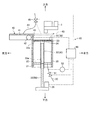
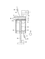
図1は、本発明の実施の形態である飲料抽出方法を実施する飲料抽出装置を模式的に示す模式図であり、一部を断面で示している。 FIG. 1 is a schematic view schematically showing a beverage extraction apparatus for performing a beverage extraction method according to an embodiment of the present invention, and a part thereof is shown in cross section.
ここで例示する飲料抽出装置10は、コーヒーや紅茶等の飲料を提供する飲料サーバーやカップ式飲料自動販売機等に適用されるものであり、ミル1から提供されたコーヒー原料(粉砕豆:飲料原料)と、供給される湯とからコーヒー飲料を抽出するものである。
The
このような飲料抽出装置10は、シリンダ20と、ピストンユニット30と、カバー部材40と、抽出経路50とを備えて構成されている。
Such a
シリンダ20は、下面に形成された下面開口21が底部22により閉塞された有底円筒状を成すものである。このようなシリンダ20は、図示せぬシリンダホルダにより支持されており、軸方向が上下方向に一致している。
The
ピストンユニット30は、メッシュ部材31と、送りナット32と、送りネジ33とを備えて構成されている。メッシュ部材31は、例えば金属材料から構成されたもので、円板状の形態を成している。このメッシュ部材31は、側面がシリンダ20の内面に接しており、複数の貫通孔31aが上下に貫通する態様で形成されている。
The
送りナット32は、上下方向が長手方向となる長尺状部材であり、メッシュ部材31の下面の中央部分に取付ブロック34を介して取り付けられている。この送りナット32は、上面の開口が取付ブロック34により閉塞された円筒状の形態を成しており、底部22の中央部分に形成されたナット用孔部22aを貫通している。ここで送りナット32の外径は、ナット用孔部22aの内径よりも僅かに小さいものであり、送りナット32とナット用孔部22aとの隙間にはパッキン等が設けられることにより気密性が確保されている。
The
送りネジ33は、上下方向が長手方向となる長尺状部材であり、一部が送りナット32の内部に進入している。この送りネジ33は、送りナット32の内部に進入する外側面が該送りナット32の内側面に螺合している。かかる送りネジ33は、下端部がピストンモータ35が連係されている。ピストンモータ35は、制御部(制御手段)60から与えられる指令に応じて正逆回転可能に駆動するものである。
The
よって、上記送りネジ33は、ピストンモータ35が正転駆動する場合には、自身の中心軸回りに例えば上方から見て時計回りに回転することにより螺合する送りナット32を下方に向けて移動させる一方、ピストンモータ35が逆転駆動する場合には、中心軸回りに例えば上方から見て反時計回りに回転することにより送りナット32を上方に向けて移動させるものである。
Therefore, when the
このように送りネジ33の回転により送りナット32が上下方向に沿って移動することで、取付ブロック34を介して該送りナット32が取り付けられるメッシュ部材31は、側面がシリンダ20の内面に接した状態で底部22に近接離反する態様で移動可能である。
As the
カバー部材40は、シリンダ20の上方域に設けられている。このようなカバー部材40は、下壁部及び左壁部が開口した箱状の形態を成しており、上壁部41がシリンダ20の上面開口23を覆うのに十分な大きさを有している。
The
このようなカバー部材40は、カバーモータ42に連係されている。カバーモータ42は、制御部60から与えられる指令に応じて正逆回転可能に駆動するものである。
Such a
よって、上記カバー部材40は、カバーモータ42が正転駆動する場合には、右方に向けて移動して、図1中の破線で示すようにシリンダ20の上面開口23を閉塞する第1位置まで移動する一方、カバーモータ42が逆転駆動する場合には、左方に向けて移動して、図1中の実線で示すようにシリンダ20の上面開口23を開放する第2位置まで移動するものである。つまり、カバー部材40は、上面開口23を閉塞する第1位置と該上面開口23を開放する第2位置との間で移動可能に設けられている。
Therefore, when the
上記カバー部材40は、スクレーパ部43及び供給経路44を有している。スクレーパ部43は、カバー部材40の右壁部により構成されている。このスクレーパ部43は、カバー部材40が第1位置と第2位置との間で移動する際に、下端部がシリンダ20の上面に摺接するようその上下寸法が決められている。
The
供給経路44は、カバー部材40の上壁部41に接続されており、図示せぬ湯タンクから供給される湯を通過させるものである。この供給経路44には、供給弁45が設けられている。供給弁45は、制御部60から与えられる指令に応じて開閉する弁体であり、開となる場合には、供給経路44を湯が通過することを許容する一方、閉となる場合には、供給経路44を湯が通過することを規制するものである。
The
抽出経路50は、底部22に設けられた図示せぬ抽出孔を貫通する態様で該底部22に接続されている。この抽出経路50は、シリンダ20の内部で抽出されたコーヒー飲料を通過させて飲料容器2(図8参照)に吐出するものである。この抽出経路50には、抽出弁51及び圧力センサ52が設けられている。
The
抽出弁51は、制御部60から与えられる指令に応じて開閉する弁体であり、開となる場合には、抽出経路50をコーヒー飲料が通過することを許容する一方、閉となる場合には、抽出経路50をコーヒー飲料が通過することを規制するものである。
The
圧力センサ52は、抽出弁51よりも上流側に設けられている。この圧力センサ52は、シリンダ20の内部におけるメッシュ部材31の下部の圧力を検知するものである。この圧力センサ52は、検知した圧力を圧力信号として制御部60に与えるものである。
The
上述したような構成を有する飲料抽出装置10の抽出動作、すなわち飲料抽出方法について以下に説明する。
The extraction operation of the
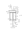
待機状態においては、図2に示すように、メッシュ部材31がシリンダ20の上面と同等の高さレベルの上死点位置に配置されて上面開口23を閉成するとともに、カバー部材40が第1位置に配置される。また、供給弁45及び抽出弁51はともに閉となっている。
In the standby state, as shown in FIG. 2, the
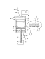
上記待機状態から開始指令が与えられた場合、制御部60は、ピストンモータ35に駆動指令を与えて該ピストンモータ35を正転駆動させる。これにより、送りネジ33が上方から見て時計回りに回転することでメッシュ部材31が送りナット32とともに下方に移動する。そして、メッシュ部材31が底部22及び上面開口23から離隔する中間位置まで移動した場合に、制御部60はピストンモータ35に駆動停止指令を与える。この結果、メッシュ部材31は、図3に示すように、中間位置に配置される。
When a start command is given from the standby state, the
また制御部60は、上記ピストンモータ35に対する駆動指令と並行して、カバーモータ42に駆動指令を与えて該カバーモータ42を逆転駆動させる。これにより、カバー部材40は、第1位置から左方に向けて移動する。そして、カバー部材40が第2位置まで移動した場合に、制御部60はカバーモータ42に駆動停止指令を与える。この結果、カバー部材40は、図3に示すように、第2位置に配置される。このようにしてシリンダ20の上面開口23は開放され、ミル1からのコーヒー原料の投入待ちとなる。
The
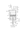
ミル1よりコーヒー原料がシリンダ20の内部に投入されると、これらコーヒー原料はメッシュ部材31の上面に堆積する。ミル1からのコーヒー原料の投入が終了すると、制御部60は、カバーモータ42に駆動指令を与えて該カバーモータ42を正転駆動させる。これにより、カバー部材40は、第2位置から右方に向けて移動する。そして、カバー部材40が第1位置まで移動した場合に、制御部60はカバーモータ42に駆動停止指令を与える。この結果、カバー部材40は、図4に示すように、第1位置に配置される。この場合、シリンダ20の上面開口23は、カバー部材40により閉塞される。
When coffee raw materials are charged into the
カバー部材40が第1位置に配置された後、制御部60は、供給弁45に開指令を与えて該供給弁45を開にさせる。これにより、湯タンクからの湯が供給経路44を通過してシリンダ20に投入される。供給弁45の開時間が予め決められた時間に達すると、制御部60は、供給弁45に閉指令を与えて該供給弁45に閉にさせる。これにより、シリンダ20には、所定量の湯が投入されたことになる(以上、投入工程)。
After the
このように投入工程においてコーヒー原料及び湯が投入されたシリンダ20の内部においては、抽出弁51が閉とされていることにより、中間位置のメッシュ部材31の下部に空気が滞留することになる。
Thus, in the inside of the
かかる投入工程の後、制御部60は、ピストンモータ35に駆動指令を与えて該ピストンモータ35を正転駆動させる。これにより、送りネジ33が上方から見て時計回りに回転することでメッシュ部材31が送りナット32とともに下方に移動する。このようにメッシュ部材31が下方に移動する結果、シリンダ20の内部におけるメッシュ部材31の下方の圧力が上昇して正圧となる。
After the charging step, the
そして、メッシュ部材31の下方の正圧の空気が該メッシュ部材31の貫通孔31aを通過してエアバブルABが生じ、かかるエアバブルABによりコーヒー原料と湯との撹拌が行われる(撹拌工程)。このようなコーヒー原料と湯との撹拌は、メッシュ部材31が底部22に最も近接する下死点位置に至るまで行われる。
Then, positive pressure air below the
ところで、シリンダ20の内部におけるメッシュ部材31の下方の圧力は圧力センサ52により検知され、その検知結果が圧力信号として制御部60に与えられる。よって、制御部60は、圧力センサ52から与えられる圧力値(圧力結果)が予め設定された所定圧力値となるようにピストンモータ35をPWM制御してもよい。
Incidentally, the pressure below the
図5に示すように、メッシュ部材31が下死点位置に達した場合、制御部60はピストンモータ35に駆動停止指令を与える。その後、制御部60は、ピストンモータ35に駆動停止指令を与えてから所定時間が経過するまでメッシュ部材31を下死点位置に待機させる(静置工程)。
As shown in FIG. 5, when the
これにより、コーヒー原料と湯との撹拌後のコーヒー原料がメッシュ部材31の上面に沈殿して沈殿物Dとなり、図5に拡大して示すように、メッシュ部材31の上面に微粉状のコーヒー原料(以下、微粉状原料ともいう)D1が沈殿し、その微粉状原料D1の上部に該微粉状原料D1よりも径が大きいコーヒー原料(以下、粉状原料ともいう)D2が沈殿する。
As a result, the coffee raw material after stirring the coffee raw material and hot water precipitates on the upper surface of the
かかる静置工程の後、制御部60は、ピストンモータ35に駆動指令を与えて該ピストンモータ35を逆転駆動させる。これにより、送りネジ33が上方から見て反時計回りに回転することでメッシュ部材31が送りナット32とともに上方に移動する。
After the stationary step, the
このようにメッシュ部材31が上方に移動する結果、図6に示すように、コーヒー原料と湯との撹拌液が貫通孔31aを通過して、メッシュ部材31の下方にコーヒー飲料を抽出させることができる(抽出工程)。
As a result of the
この場合において、撹拌液は、メッシュ部材31の沈殿物を通過するので、抽出されたコーヒー飲料は濾過されたものとなる。また、制御部60は、圧力センサ52から与えられる圧力値(圧力結果)が予め設定された所定圧力値となるようにピストンモータ35をPWM制御することが好ましい。
In this case, since the stirring liquid passes through the precipitate of the
そして、図7に示すようにメッシュ部材31が上死点位置に達した場合、制御部60はピストンモータ35に駆動停止指令を与えることで抽出工程を終了する。このとき、メッシュ部材31の上面に抽出滓Kが載置されている。
Then, when the
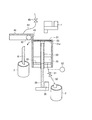
このようにして抽出工程が終了した後、制御部60は、カバーモータ42に駆動指令を与えて該カバーモータ42を逆転駆動させる。これにより、カバー部材40は、第1位置から左方に向けて移動する。この場合、カバー部材40のスクレーパ部43が上死点位置のメッシュ部材31の上面に摺接することで、メッシュ部材31の上面に載置された抽出滓Kを掻き取り、図8に示すように、シリンダ20の左方側に配置された滓容器3に抽出滓Kを収容させることができる。このようにしてカバー部材40が第2位置まで移動した場合に、制御部60はカバーモータ42に駆動停止指令を与える。
After the extraction process is thus completed, the
また制御部60は、上記カバーモータ42に対する駆動指令と並行して、抽出弁51に開指令を与える。これにより抽出弁51が開となり、シリンダ20に貯留されたコーヒー飲料が抽出経路50を通過して、飲料容器2に吐出される(吐出工程)。
In addition, the
このようにして飲料容器2に所定量のコーヒー飲料が吐出されることで、利用者にコーヒー飲料が提供されることとなる。
In this way, a predetermined amount of coffee beverage is discharged into the
このようにして吐出工程を終了した後、制御部60は、抽出弁51に閉指令を与えるとともにカバーモータ42に駆動指令を与えて該カバーモータ42を正転駆動させる。これにより、カバー部材40は、第1位置に配置され、上述した待機状態に戻る。
After the discharge process is completed in this manner, the
以上説明したように、上記飲料抽出装置10によれば、カバー部材40のスクレーパ部43が、該カバー部材40が第1位置から第2位置まで移動する場合に、上面開口23を閉成するメッシュ部材31に載置された抽出滓Kを除去するので、抽出滓Kを収容する滓容器3をシリンダ20の横に設置することができる。そのため、飲料抽出装置10と滓容器3との設置領域の高さ寸法が大きくなることを回避しながら滓容器3の容量を十分に大きくすることができる。従って、抽出滓Kの収容量の増大化を図ることができる。
As described above, according to the
このように抽出滓Kの収容量の増大化を図ることができるので、コーヒー飲料の提供回数に対する滓容器3の廃棄作業の回数の割合を低減させることができ、飲料抽出装置10が適用された飲料サーバー等の管理者の負担を減らすことができる。
Thus, since the amount of the extracted straw K can be increased, the ratio of the number of times the waste container 3 is disposed with respect to the number of coffee drinks provided can be reduced, and the
上記飲料抽出装置10によれば、カバー部材40は、コーヒー原料の投入時及び抽出したコーヒー飲料の吐出時以外には第1位置に配置されるので、コーヒー飲料が有する香気成分の散逸が抑制できるとともに、ミル1に湯気が達することでミル1の出口が閉塞される事態を回避することができる。
According to the
上記飲料抽出装置10によれば、カバー部材40は、湯を供給するため供給経路44が接続されているので、浮遊菌から保護することができる。
According to the
上記飲料抽出装置10によれば、制御部60が、開始指令が与えられた場合に、抽出弁51を閉とさせつつメッシュ部材31を中間位置に配置させ、メッシュ部材31の上面にコーヒー原料及び湯が投入された場合に、メッシュ部材31を下方に移動させるので、シリンダ20の内部におけるメッシュ部材31の下方の空気を圧縮してエアバブルABにしてコーヒー原料と湯とを撹拌させることができる。よって、エアポンプ等の動力源を用いることなくコーヒー原料と湯との撹拌を良好に行うことができる。
According to the
本実施の形態である飲料抽出方法によれば、開始指令が与えられた場合に、抽出弁51を閉にするとともにメッシュ部材31を中間位置に配置させて、上面開口23を通じてコーヒー原料及び湯が投入されることを許容する投入工程と、投入工程により上面にコーヒー原料及び湯が投入されたメッシュ部材31を、底部22に近接するよう移動させることにより、貫通孔31aを通過するエアによりコーヒー原料と湯とを撹拌させる撹拌工程と、撹拌工程により下死点位置まで移動したメッシュ部材31を予め決められた時間待機させる静置工程と、静置工程により待機させたメッシュ部材31を底部22から離隔するよう移動させてコーヒー飲料を抽出する抽出工程と、抽出工程により上面開口23に近接する位置までメッシュ部材31が移動した場合に、抽出弁51を開にして抽出経路50を通じて抽出したコーヒー飲料を吐出する吐出工程とを含むので、エアポンプ等の動力源を用いることなくコーヒー原料と湯との撹拌を良好に行うことができる。
According to the beverage extraction method of the present embodiment, when a start command is given, the
以上、本発明の好適な実施の形態について説明したが、本発明はこれに限定されるものではなく、種々の変更を行うことができる。 The preferred embodiment of the present invention has been described above, but the present invention is not limited to this, and various modifications can be made.
上述した実施の形態では、カバー部材40は、下壁部及び左壁部が開口した箱状の形態を成し、かつ右壁部がスクレーパ部43を構成していたが、本発明においては、カバー部材の形態は特に限定されるものではなく、種々の形態を採用することができる。
In the above-described embodiment, the
上述した実施の形態では、静置工程が含まれていたが、本発明においては、静置工程が含まれていなくても良い。 In the above-described embodiment, the stationary process is included. However, in the present invention, the stationary process may not be included.
10 飲料抽出装置
20 シリンダ
21 下面開口
22 底部
23 上面開口
30 ピストンユニット
31 メッシュ部材
31a 貫通孔
32 送りナット
33 送りネジ
35 ピストンモータ
40 カバー部材
42 カバーモータ
43 スクレーパ部
44 供給経路
45 供給弁
50 抽出経路
51 抽出弁
52 圧力センサ
60 制御部(制御手段)
DESCRIPTION OF
Claims (3)
開始指令が与えられた場合に、前記抽出経路に設けられた抽出弁を閉にして該抽出経路を飲料が通過することを規制するとともに、複数の貫通孔が形成された円板状を成して側面が前記シリンダの内面に接するメッシュ部材を前記底部及び該シリンダの上面開口から離隔した中間位置に配置させて、該上面開口を通じて飲料原料及び湯が投入されることを許容する投入工程と、
前記投入工程により上面に前記飲料原料及び前記湯が投入された前記メッシュ部材を、前記底部に近接するよう移動させることにより、前記貫通孔を通過するエアにより前記飲料原料と前記湯とを撹拌させる撹拌工程と、
前記撹拌工程により前記底部に近接する位置まで移動したメッシュ部材を、該底部から離隔するよう移動させて飲料を抽出する抽出工程と、
前記抽出工程により前記上面開口に近接する位置までメッシュ部材が移動した場合に、前記抽出弁を開にして前記抽出経路を通じて抽出した飲料を吐出する吐出工程と
を含むことを特徴とする飲料抽出方法。 A beverage extraction method for extracting a beverage from a beverage raw material and hot water charged in a bottomed cylindrical cylinder whose bottom opening is closed at the bottom, and discharging the extracted beverage through an extraction path connected to the bottom,
When a start command is given, the extraction valve provided in the extraction path is closed to restrict the beverage from passing through the extraction path, and the disk is formed with a plurality of through holes. A loading step of allowing a beverage ingredient and hot water to be charged through the top surface opening by disposing a mesh member whose side surface is in contact with the inner surface of the cylinder at an intermediate position spaced from the bottom and the top surface opening of the cylinder;
The beverage ingredient and the hot water are agitated by the air passing through the through-hole by moving the mesh member in which the beverage ingredient and the hot water are introduced on the upper surface in the charging step so as to be close to the bottom. A stirring step;
An extraction step of extracting the beverage by moving the mesh member moved to a position close to the bottom by the stirring step so as to be separated from the bottom; and
A beverage extraction method comprising: a discharging step of opening the extraction valve and discharging the beverage extracted through the extraction path when the mesh member moves to a position close to the upper surface opening by the extraction step. .
前記抽出工程は、前記静置工程により待機させたメッシュ部材を、該底部から離隔するよう移動させて飲料を抽出することを特徴とする請求項1に記載の飲料抽出方法。 Including a stationary step of waiting for a predetermined time, the mesh member moved to a position close to the bottom by the stirring step,
The beverage extraction method according to claim 1, wherein the extraction step extracts the beverage by moving the mesh member waiting in the stationary step so as to be separated from the bottom portion.
Priority Applications (1)
| Application Number | Priority Date | Filing Date | Title |
|---|---|---|---|
| JP2016094302A JP6852280B2 (en) | 2016-05-10 | 2016-05-10 | Beverage extraction method |
Applications Claiming Priority (1)
| Application Number | Priority Date | Filing Date | Title |
|---|---|---|---|
| JP2016094302A JP6852280B2 (en) | 2016-05-10 | 2016-05-10 | Beverage extraction method |
Publications (2)
| Publication Number | Publication Date |
|---|---|
| JP2017202041A true JP2017202041A (en) | 2017-11-16 |
| JP6852280B2 JP6852280B2 (en) | 2021-03-31 |
Family
ID=60321246
Family Applications (1)
| Application Number | Title | Priority Date | Filing Date |
|---|---|---|---|
| JP2016094302A Active JP6852280B2 (en) | 2016-05-10 | 2016-05-10 | Beverage extraction method |
Country Status (1)
| Country | Link |
|---|---|
| JP (1) | JP6852280B2 (en) |
Cited By (1)
| Publication number | Priority date | Publication date | Assignee | Title |
|---|---|---|---|---|
| JP2019111070A (en) * | 2017-12-22 | 2019-07-11 | パナソニックIpマネジメント株式会社 | Beverage extraction apparatus |
Citations (3)
| Publication number | Priority date | Publication date | Assignee | Title |
|---|---|---|---|---|
| JP2003528673A (en) * | 2000-03-31 | 2003-09-30 | デ・ヨン・ドゥーケ | Coffee making device with pressure control unit |
| JP2006244448A (en) * | 2005-02-02 | 2006-09-14 | Kubota Corp | Beverage extractor |
| US20150107459A1 (en) * | 2012-12-14 | 2015-04-23 | Vki Technologies Inc. | System and method for making a beverage |
-
2016
- 2016-05-10 JP JP2016094302A patent/JP6852280B2/en active Active
Patent Citations (3)
| Publication number | Priority date | Publication date | Assignee | Title |
|---|---|---|---|---|
| JP2003528673A (en) * | 2000-03-31 | 2003-09-30 | デ・ヨン・ドゥーケ | Coffee making device with pressure control unit |
| JP2006244448A (en) * | 2005-02-02 | 2006-09-14 | Kubota Corp | Beverage extractor |
| US20150107459A1 (en) * | 2012-12-14 | 2015-04-23 | Vki Technologies Inc. | System and method for making a beverage |
Cited By (2)
| Publication number | Priority date | Publication date | Assignee | Title |
|---|---|---|---|---|
| JP2019111070A (en) * | 2017-12-22 | 2019-07-11 | パナソニックIpマネジメント株式会社 | Beverage extraction apparatus |
| JP7210137B2 (en) | 2017-12-22 | 2023-01-23 | パナソニックIpマネジメント株式会社 | beverage extraction equipment |
Also Published As
| Publication number | Publication date |
|---|---|
| JP6852280B2 (en) | 2021-03-31 |
Similar Documents
| Publication | Publication Date | Title |
|---|---|---|
| CN101155536A (en) | Device and disposable capsule for producing liquid products, in particular beverages | |
| US11219332B2 (en) | Beverage extraction device | |
| JP2017202041A (en) | Beverage extraction method | |
| CN107204073B (en) | Cup type vending machine | |
| JP2017202044A (en) | Beverage extraction apparatus | |
| KR102231060B1 (en) | Beverage extraction device | |
| KR101496342B1 (en) | Dutch coffee extraction apparatus | |
| CN112839550A (en) | Beverage supply device | |
| JP2731186B2 (en) | Beverage extractor | |
| KR101670426B1 (en) | Extracting apparatus for food | |
| JP6929359B2 (en) | Beverage preparation machine discharge powder material collection container | |
| JP6866735B2 (en) | Beverage extractor | |
| JP4155195B2 (en) | Beverage extractor | |
| JP7365606B2 (en) | beverage extraction equipment | |
| JP6816599B2 (en) | Beverage extractor | |
| CN112804918A (en) | Beverage supply device | |
| JP2020089472A (en) | Beverage extraction apparatus | |
| CN214181890U (en) | Draw jar with filtering capability | |
| WO2018116736A1 (en) | Beverage extraction device | |
| JP7251109B2 (en) | beverage dispenser | |
| KR200314566Y1 (en) | Bean curdling apparatus | |
| JP7215120B2 (en) | beverage extraction equipment | |
| JP2010029489A (en) | Beverage dispenser device | |
| JP2002320551A (en) | Beverage extracting machine | |
| JP2005055934A (en) | Beverage extractor |
Legal Events
| Date | Code | Title | Description |
|---|---|---|---|
| A621 | Written request for application examination |
Free format text: JAPANESE INTERMEDIATE CODE: A621 Effective date: 20190415 |
|
| A131 | Notification of reasons for refusal |
Free format text: JAPANESE INTERMEDIATE CODE: A131 Effective date: 20200212 |
|
| A977 | Report on retrieval |
Free format text: JAPANESE INTERMEDIATE CODE: A971007 Effective date: 20200214 |
|
| A521 | Request for written amendment filed |
Free format text: JAPANESE INTERMEDIATE CODE: A523 Effective date: 20200408 |
|
| A131 | Notification of reasons for refusal |
Free format text: JAPANESE INTERMEDIATE CODE: A131 Effective date: 20200707 |
|
| A521 | Request for written amendment filed |
Free format text: JAPANESE INTERMEDIATE CODE: A523 Effective date: 20200903 |
|
| TRDD | Decision of grant or rejection written | ||
| A01 | Written decision to grant a patent or to grant a registration (utility model) |
Free format text: JAPANESE INTERMEDIATE CODE: A01 Effective date: 20210209 |
|
| A61 | First payment of annual fees (during grant procedure) |
Free format text: JAPANESE INTERMEDIATE CODE: A61 Effective date: 20210222 |
|
| R150 | Certificate of patent or registration of utility model |
Ref document number: 6852280 Country of ref document: JP Free format text: JAPANESE INTERMEDIATE CODE: R150 |
|
| R250 | Receipt of annual fees |
Free format text: JAPANESE INTERMEDIATE CODE: R250 |
|
| R250 | Receipt of annual fees |
Free format text: JAPANESE INTERMEDIATE CODE: R250 |
|
| R250 | Receipt of annual fees |
Free format text: JAPANESE INTERMEDIATE CODE: R250 |