JP2017205152A - Mold and pattern sheet manufacturing method - Google Patents
Mold and pattern sheet manufacturing method Download PDFInfo
- Publication number
- JP2017205152A JP2017205152A JP2016097826A JP2016097826A JP2017205152A JP 2017205152 A JP2017205152 A JP 2017205152A JP 2016097826 A JP2016097826 A JP 2016097826A JP 2016097826 A JP2016097826 A JP 2016097826A JP 2017205152 A JP2017205152 A JP 2017205152A
- Authority
- JP
- Japan
- Prior art keywords
- mold
- sheet
- pattern
- concave
- back surface
- Prior art date
- Legal status (The legal status is an assumption and is not a legal conclusion. Google has not performed a legal analysis and makes no representation as to the accuracy of the status listed.)
- Granted
Links
Images














Landscapes
- Media Introduction/Drainage Providing Device (AREA)
Abstract
【課題】滑り性のよいモールドを提供すること、及びパターンシートのスループットを上げることができるパターンシートの製造方法を提供する。
【解決手段】
実施形態のモールド10の裏面12Bの一部には凹凸部18が形成され、透明ガラス基板66に対する滑り性が改善されている。これにより、モールド10の裏面12Bは、透明ガラス基板66に密着せず、透明ガラス基板66に対して滑りながら位置決めされる。したがって、検査工程にてモールド10の裏面12Bが透明ガラス基板66に密着することに起因する検査時間のロスを無くすことができるので、MNAのスループットの低下を防止することができる。
【選択図】図3The present invention provides a mold having good slipperiness and a pattern sheet manufacturing method capable of increasing the throughput of the pattern sheet.
[Solution]
An uneven portion 18 is formed on a part of the back surface 12B of the mold 10 of the embodiment, and the slipperiness with respect to the transparent glass substrate 66 is improved. As a result, the back surface 12 </ b> B of the mold 10 is positioned without sliding on the transparent glass substrate 66 while being in close contact with the transparent glass substrate 66. Therefore, the loss of inspection time caused by the back surface 12B of the mold 10 being in close contact with the transparent glass substrate 66 in the inspection process can be eliminated, so that a reduction in MNA throughput can be prevented.
[Selection] Figure 3
Description
本発明はモールド及びパターンシートの製造方法に係り、特にマイクロニードルアレイを製造するためのモールド及びパターンシートの製造方法に関する。 The present invention relates to a mold and a pattern sheet manufacturing method, and more particularly to a mold and a pattern sheet manufacturing method for manufacturing a microneedle array.
近年、痛みを伴わずにインシュリン(Insulin)、ワクチン(Vaccines)及び人成長ホルモン(hGH:human Growth Hormone)等の薬剤を皮膚内に投与可能な新規剤型として、マイクロニードルアレイ(Micro-Needle Array:以下、「MNA」と略す。)が知られている。MNAは、薬剤を含み、生分解性のある複数のマイクロニードル(微細針または微小針とも言う。)をアレイ状に配置したものである。このMNAを皮膚に貼付することにより、マイクロニードルが皮膚に突き刺さり、マイクロニードルが皮膚内で吸収され、マイクロニードルに含まれた薬剤が皮膚内に投与される。 In recent years, Micro-Needle Array (Micro-Needle Array) has been developed as a new dosage form that can administer drugs such as insulin, vaccine (Vaccines) and human growth hormone (hGH) without causing pain. : Hereinafter abbreviated as “MNA”). MNA includes a drug and a plurality of biodegradable microneedles (also referred to as microneedles or microneedles) arranged in an array. By affixing this MNA to the skin, the microneedle pierces the skin, the microneedle is absorbed in the skin, and the drug contained in the microneedle is administered into the skin.
このようなMNAの製造方法としては、その表面にマイクロニードルの反転型である複数の針状凹部(以下、「凹状パターン」と言う。)を有するモールドを製造し、このモールドの凹状パターンに、薬剤等を含む薬剤水溶液を供給して乾燥させることでMNAを成形した後、MNAをモールドから剥離する方法が知られている(特許文献1)。 As a method for producing such an MNA, a mold having a plurality of needle-like recesses (hereinafter referred to as “concave pattern”) which is a reversal type of microneedles on its surface is manufactured, A method is known in which an MNA is molded by supplying a chemical aqueous solution containing a drug or the like and dried, and then the MNA is peeled from the mold (Patent Document 1).
MNAの製造工程は、モールドの凹状パターンに薬剤水溶液を供給する供給工程と、薬剤水溶液を乾燥させてMNAに成形する乾燥工程との間に、凹状パターンに供給された薬剤水溶液の供給量を検査する検査工程が存在する。この検査工程は、例えば、高精度電子天秤の検査台にモールドの裏面を載置することにより行われる。具体的には、薬剤水溶液の供給前のモールドの重量を、供給工程の前段階で予め測定しておき、そして、薬剤水溶液の供給後のモールドの重量を検査工程で測定し、薬剤水溶液の供給前後の重量差を求めることで、薬剤水溶液の供給量を求めている。 The MNA manufacturing process inspects the supply amount of the chemical aqueous solution supplied to the concave pattern between the supply step of supplying the chemical aqueous solution to the concave pattern of the mold and the drying step of drying the chemical aqueous solution to form the MNA. There is an inspection process to do. This inspection process is performed, for example, by placing the back surface of the mold on an inspection table of a high-precision electronic balance. Specifically, the weight of the mold before the supply of the chemical aqueous solution is measured in advance before the supply process, and the weight of the mold after the supply of the chemical aqueous solution is measured in the inspection process to supply the chemical aqueous solution. The supply amount of the aqueous drug solution is obtained by obtaining the weight difference between before and after.
しかしながら、従来のモールドは、前述した検査工程において、モールドの裏面が高精度電子天秤の検査台に密着するため、モールドを検査台から容易に取り外すことができない場合があった。特に、シリコーンゴム製のモールドは、柔軟であるが故に検査台に強く密着してしまう。このようなモールドの密着問題に起因して、従来では、MNAのスループット(生産量)を上げることができないという問題があった。 However, the conventional mold sometimes cannot be easily removed from the inspection table because the back surface of the mold is in close contact with the inspection table of the high-precision electronic balance in the inspection process described above. In particular, a silicone rubber mold adheres strongly to the examination table because it is flexible. Due to such a mold adhesion problem, conventionally, there has been a problem that the throughput (production amount) of MNA cannot be increased.
本発明は、このような事情に鑑みてなされたもので、滑り性のよいモールドを提供すること、及びパターンシートのスループットを上げることができるパターンシートの製造方法を提供することを目的とする。 This invention is made | formed in view of such a situation, and it aims at providing the manufacturing method of the pattern sheet | seat which can raise the throughput of a pattern sheet | seat which can provide a mold with good slipperiness.
本発明の一態様のモールドは、シートの表面に複数の凹部からなる凹状パターンがアレイ状に配置されてなるモールドにおいて、シートの裏面の一部に凹凸部が配置される。 The mold of one embodiment of the present invention is a mold in which concave patterns including a plurality of concave portions are arranged in an array on the surface of the sheet, and the concave and convex portions are arranged on a part of the back surface of the sheet.
本発明の一態様は、モールドの凹部は針状凹部であることが好ましい。 In one embodiment of the present invention, the concave portion of the mold is preferably a needle-like concave portion.
本発明の一態様は、シートの表面の凹状パターンの配置領域に対向する、シートの裏面の領域は平坦面とされ、シートの表面の凹状パターンの非配置領域に対向する、シートの裏面の領域に凹凸部が配置されることが好ましい。 One embodiment of the present invention is an area on the back side of the sheet that faces the arrangement area of the concave pattern on the surface of the sheet, the area on the back side of the sheet is a flat surface, and faces the non-arrangement area of the concave pattern on the surface of the sheet. It is preferable that the concavo-convex part is disposed on the surface.
本発明の一態様は、シートの裏面において、凹凸部の配置領域面は、配置領域面を除く領域面に対して突出されていることが好ましい。 In one embodiment of the present invention, on the back surface of the sheet, it is preferable that the arrangement region surface of the concavo-convex part protrudes from the region surface excluding the arrangement region surface.
本発明の一態様は、モールドのショアA硬度が35以上60以下であることが好ましい。 In one embodiment of the present invention, the Shore A hardness of the mold is preferably 35 or more and 60 or less.
本発明の一態様は、モールドは、シリコーンゴム製であることが好ましい。 In one embodiment of the present invention, the mold is preferably made of silicone rubber.
本発明の一態様のパターンシートの製造方法は、本発明のモールドを使用し、モールドのシートの表面に配置された凹状パターンにポリマー溶解液を供給する供給工程と、モールドのシートの裏面を検査台に載置して凹状パターンに供給されたポリマー溶解液の供給量を検査する検査工程と、ポリマー溶解液を乾燥させてパターンシートに成形する乾燥工程と、パターンシートをモールドから剥離するパターンシート剥離工程と、を含む。 The pattern sheet manufacturing method according to one aspect of the present invention uses the mold of the present invention to supply a polymer solution to a concave pattern disposed on the surface of the mold sheet, and inspects the back surface of the mold sheet. An inspection process for inspecting the amount of the polymer solution supplied to the concave pattern placed on the table, a drying process for drying the polymer solution to form a pattern sheet, and a pattern sheet for peeling the pattern sheet from the mold And a peeling step.
本発明のモールドによれば、滑り性のよいモールドを提供することができる。また、本発明のパターンシートの製造方法によれば、パターンシートのスループットを上げることができる。 According to the mold of the present invention, a mold having good sliding properties can be provided. Moreover, according to the method for producing a pattern sheet of the present invention, the throughput of the pattern sheet can be increased.
以下、添付図面に従って本発明の好ましい実施形態について説明する。 Hereinafter, preferred embodiments of the present invention will be described with reference to the accompanying drawings.
実施形態では、本発明のパターンシートとしてMNAを例示して説明するが、本発明のパターンシートはMNAに限定されず、その表面に複数の突起を有する突起状パターンがアレイ状に配置されたパターンシートであれば適用できる。すなわち、本発明のモールドは、MNAを製造するモールドに限定されず、突起状パターンがアレイ状に配置されたパターンシートを製造するモールドであれば適用できる。なお、MNAは、パターンシートを突起状パターンごとに切断することにより、1枚のパターンシートから突起状パターンの数だけ得られるものである。 In the embodiment, the MNA is exemplified and described as the pattern sheet of the present invention. However, the pattern sheet of the present invention is not limited to the MNA, and a pattern in which protruding patterns having a plurality of protrusions are arranged in an array on the surface thereof. Any sheet can be applied. That is, the mold of the present invention is not limited to a mold for manufacturing MNA, and can be applied as long as it is a mold for manufacturing a pattern sheet in which protruding patterns are arranged in an array. In addition, MNA is obtained by the number of protrusion patterns from one pattern sheet by cutting the pattern sheet for each protrusion pattern.
〔モールド10〕
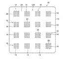
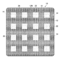
図1は、実施形態のモールド10の表面の正面図であり、図2は、モールド10の裏面の背面図であり、図3は、図1はモールド10の断面図である。
[Mold 10]
FIG. 1 is a front view of the front surface of the
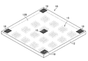
図1に示すモールド10は、矩形状のシート12の表面12Aに16個の凹部14からなる16個の凹状パターン16がアレイ状に配置され、図2に示すようにシート12の裏面12Bの一部に凹凸部18が配置されて構成される。
In the
また、実施形態のモールド10の凹部14は、図3に示すように針状凹部であることが好ましい。また、図1〜図3に示すように、シート12の表面12Aの凹状パターン16の配置領域20に対向する、シート12の裏面12Bの領域22は平坦面とされ、シート12の表面12Aの凹状パターン16の非配置領域24に対向する、シート12の裏面12Bの領域26に凹凸部18が配置されていることが好ましい。また、図3に示すように、シート12の裏面12Bにおいて、凹凸部18の配置領域面26Aは、配置領域面26Aを除く領域面22Aに対して10〜100μm程度突出されていることが好ましい。なお、この突出量は、領域面22Aに対する凹凸部18の凸部の頂部の高さと等価である。また、モールド10は、ショアA硬度(JIS K6253)が35以上60以下のシリコーンゴム製であることが好ましい。
Moreover, it is preferable that the
実施形態のモールド10は、後述する射出成形用の金型のキャビティに電鋳金型30(図15参照)をインサートし、キャビティにシリコーンゴムを射出することにより製造される。まず、電鋳金型30の製造方法について説明する。
The
<電鋳金型30の製造方法>
図4〜図8は、電鋳金型30を製造するモールド32の製造方法の一例を示した工程図である。図9は原版34の斜視図である。
<Method for manufacturing
4 to 8 are process diagrams showing an example of a method for manufacturing the
図4及び図9に示すように、原版34の表面34Bには突起状パターン34Aが形成されている。原版34の突起状パターン34Aは、最終製品のMNAの突起状パターンと等価である。
As shown in FIGS. 4 and 9, a
原版34は、母材である金属基板をダイヤモンドバイト等の切削工具等を用いて機械加工することにより製造される。金属基板としては、ステンレス、アルミニウム合金、ニッケル等を挙げることができる。 The original 34 is manufactured by machining a metal substrate as a base material using a cutting tool such as a diamond tool. Examples of the metal substrate include stainless steel, aluminum alloy, nickel, and the like.
突起状パターン34Aとは、原版34の表面34Bから離間する方向に突出された複数(実施形態では16個)の突起部36が、原版34の表面34Bにアレイ状に配置されてなる形態をいう。突起部36の個数、突起部36の配置位置等は限定されない。また、原版34の表面34Bは完全な平面であっても、一見して平面であってもよい。
The
実施形態の突起部36は、表面34Bから離間する方向に先細りとなる針状に構成されている。突起部36は、いわゆる錐体であり、錐体として角錐、円錐等が含まれる。
The
突起部36は、例えば、原版34の表面34Bから100〜2000μmの高さを有し、Φ50μm以下の先端径を有することが好ましい。複数の突起部36を有する場合、隣り合う突起部36の間隔は300〜2000μmであることが好ましい。また、突起部36のアスペクト比(突起部36の高さ/突起部36の底面の幅)は、1〜5であることが好ましい。
For example, the
図5は、モールド32の母材である熱可塑性樹脂シート38の側面図である。熱可塑性樹脂シート38は、例えば厚さが0.5〜2.0mm、一辺の長さが100×100〜300×300mmの大きさであり、表面38Bに後述する凹状パターン32Aが形成される。熱可塑性樹脂シート38の厚さは、少なくとも、原版34の突起部36の高さ以上であることが好ましい。
FIG. 5 is a side view of a
熱可塑性樹脂シート38を構成する熱可塑性樹脂としては、例えば、ポリエチレンテレフタレート、ポリカーボネート、ポリメチルメタクリレート、ポリスチレン、ポリエチレン、液晶ポリマー、ポリ乳酸等を好適に用いることができる。熱可塑性樹脂シート38とは、膜厚が薄く、常温において自己支持性を有する状態にある熱可塑性樹脂を意味する。「自己支持性」とは、他の部材による支持がなくても、単体でその形態を保ち得ることをいう。
As the thermoplastic resin constituting the
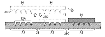
図6、図7は、位置決め工程、凹状パターン32Aを形成する形成工程、及び位置決め工程と形成工程とを繰り返し行うことを示している。
6 and 7 show that the positioning step, the forming step for forming the
図6に示すように、原版34と熱可塑性樹脂シート38と相対的に移動して、原版34を熱可塑性樹脂シート38に押圧する位置(例えば、領域A1)を決定する。位置決めは、例えば、熱可塑性樹脂シート38を支持するテーブル(不図示)に、水平面内で互いに直交方向に移動するX軸駆動機構、Y軸駆動機構を設けることにより実行される。
As shown in FIG. 6, the
原版34は、熱可塑性樹脂シート38が軟化する程度の温度に予め加熱される。加熱方法は、ヒータ(不図示)により行わる。熱可塑性樹脂シート38を構成する熱可塑性樹脂に応じて、原版34は適正な温度に加熱される。
The
次に、加熱された原版34の突起状パターン34Aを、熱可塑性樹脂シート38の表面38Bの領域A1に押圧して差し込み、熱可塑性樹脂シート38の領域A1を一定時間加熱する。
Next, the protruding
次に、突起状パターン34Aを領域A1に差し込んだ状態で、原版34を冷却することにより、領域A1を軟化温度以下になるまで冷却する。
Next, the
次に、図7に示すように、原版34と熱可塑性樹脂シート38とを引き離す。これにより、熱可塑性樹脂シート38の表面38Bの領域A1に、突起状パターン34Aの反転形状の凹状パターン32Aが形成される。
Next, as shown in FIG. 7, the
凹状パターン32Aとは、熱可塑性樹脂シート38の表面38Bから裏面38Cに向けて延びる複数の針状凹部38Dが、熱可塑性樹脂シート38の表面38Bにアレイ状に配置されてなる状態をいう。凹状パターン32Aは突起状パターン34Aの反転形状であるので、凹状パターン32Aの針状凹部38Dの大きさ、数、及び配置は、原版34の突起部36の大きさ、数、及び配置と等価である。
The
次に、領域A1に隣接する領域A2に対し、原版34と熱可塑性樹脂シート38とを位置決めする。次に、加熱された原版34の突起状パターン34Aを領域A2に押圧して差し込み、領域A2を一定時間加熱する。次いで、原版34を冷却することにより領域A2を軟化温度以下になるまで冷却する。次に、原版34と熱可塑性樹脂シート38とを引き離して、領域A2に突起状パターン34Aの反転形状の凹状パターン32Aを形成する。
Next, the
次に、領域A2に隣接する領域A3に対し、原版34と熱可塑性樹脂シート38とを位置決めし、加熱された原版34の突起状パターン34Aを領域A3に押圧して差し込み、同様の手順で領域A3に凹状パターン32Aを形成する。
Next, the
このように図6及び図7で説明した原版34と熱可塑性樹脂シート38との位置決め工程と、凹状パターン32Aを熱可塑性樹脂シート38に形成する形成工程と、を繰り返す。これにより、図8に示すように、複数の凹状パターン32Aが形成されたモールド32が製造される。
Thus, the positioning process of the
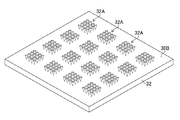
図10は、モールド32の一例を示す斜視図である。図9、図10に示すように、一つの突起状パターン34Aを有する原版34から、16個の凹状パターン32Aがアレイ状に配置された樹脂製のモールド32を製造することができる。
FIG. 10 is a perspective view showing an example of the
<モールド32を用いた電鋳金型30の製造方法>
図11〜図13は、モールド32を用いた電鋳金型30の製造方法の手順を示した工程図である。
<Method for
FIGS. 11 to 13 are process diagrams showing the procedure of the method for manufacturing the
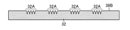
図11に示すように、モールド32の表面38Bには凹状パターン32Aが形成されている。
As shown in FIG. 11, a
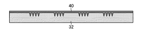
図12は、モールド32の凹状パターン32Aに、電鋳法により金属を埋める電鋳工程を示した工程図である。電鋳工程においては、まず、モールド32に対して導電化処理を行う。モールド32に、金属(例えば、ニッケル)をスパッターし、モールド32の表面38B及び凹状パターン32Aに金属を付着する。
FIG. 12 is a process diagram showing an electroforming process in which metal is filled in the
次に、導電化処理を経たモールド32を陰極に保持する。金属ペレットを金属製のケースに保持し陽極とする。モールド32を保持する陰極と金属ペレットを保持する陽極とを電鋳液中に浸漬し、通電する。電鋳法により、モールド32の凹状パターン32Aに金属を埋め込み、電鋳金型30となる金属体40を形成する。電鋳法とは、電気めっき法により型の表面に金属を析出させる方法をいう。
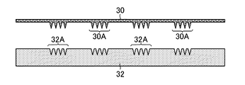
Next, the
図13は、モールド32から金属体40を剥離する剥離工程を示した工程図である。図13に示すように、金属体40をモールド32から剥離する。これにより、突起状パターン30Aを有する電鋳金型30を製造することができる。突起状パターン30Aは、モールド32の凹状パターン32Aの反転形状となる。すなわち、突起状パターン30Aは、図9に示した原版34の突起状パターン34Aと等価である。
FIG. 13 is a process diagram showing a peeling process for peeling the
〔電鋳金型30を用いたモールド10の製造方法〕
図14〜図17は、電鋳金型30を用いたモールド10の製造方法の手順を示した工程図である。
[Method for
14-17 is process drawing which showed the procedure of the manufacturing method of the
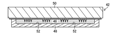
モールド10は、射出成形用の金型42のキャビティ44に電鋳金型30をインサートし、キャビティ44に硬化前のシリコーンゴム46を射出し、熱硬化し、成形品から電鋳金型30を剥離することにより製造される。
In the
金型42は、キャビティ44を有する下型48と、突起状パターン30Aがキャビティ44に向くように電鋳金型30を保持する上型50とから構成される。
The
射出成形によって電鋳金型30の形状が転写することにより、モールド10のシート12の表面12Aが成形され、この際に電鋳金型30の突起状パターン30Aの形状が転写することにより、凹状パターン16が表面12Aに成形される。また、下型48のキャビティ44の底面44Aの一部には、凹凸部52が備えられる。キャビティ44の底面44Aの形状が転写することにより、シート12の裏面12Bが成形され、この際に底面44Aの凹凸部52の形状が転写することにより、凹凸部18が裏面12Bに成形される。凹凸部52は、凹凸部18を反転させた形状であり、サンドブラスト等のシボ加工によって底面44Aに形成される。
By transferring the shape of the
実施形態では、図1〜図3に示したように、シート12の表面12Aの凹状パターン16の非配置領域24に対向する、シート12の裏面12Bの領域26に凹凸部18が配置される。このため、凹凸部18に対応した位置に凹凸部52が備えられている。具体的には、シート12の表面12Aの非配置領域24は、アレイ状の16箇所の配置領域20を除く格子状の領域なので、凹凸部52もその格子状の領域に対応した領域に備えられている。
In the embodiment, as shown in FIGS. 1 to 3, the concavo-
なお、凹凸部18の領域26は、格子状の領域に限定されず、凹凸部18の存在によってシート12の裏面12Bに滑り性を持たせることができる領域であれば、シート12の裏面12Bの任意の領域であればよい。例えば、図18のモールド10の裏面12Bのように、凹凸部18の領域は、四隅領域であっても中央領域であってもそれ以外の領域であっても構わない。
The
また、シート12の表面12Aの凹状パターン16の配置領域20に対向する、シート12の裏面12Bの領域に凹凸部18を配置してもよいが、後述する光学的な検査装置54(図27参照)を使用する検査工程によれば、非配置領域24に対向する領域26に凹凸部18を配置し、配置領域20に対向する領域22を平坦面とすることが好ましい。
Moreover, although the uneven | corrugated |
また、シート12の裏面12Bにおいて、凹凸部18の配置領域面26Aは、配置領域面26Aを除く領域面22Aに対して10〜100μm程度突出されているので、凹凸部18の突出量を考慮した深さに凹凸部52が形成されている。
Further, in the
〔モールド32を用いたMNAの製造方法〕
図19は、MNAの製造工程を示したフローチャートである。
[Manufacturing method of MNA using mold 32]
FIG. 19 is a flowchart showing the manufacturing process of MNA.
MNAの製造工程は、モールド10のシート12の表面12Aに配置された凹状パターン16にポリマー溶解液を供給する供給工程(S(Step)10)と、モールド10のシート12の裏面12Bを検査台である透明ガラス基板66(図27参照)に載置して凹状パターン16に供給されたポリマー溶解液の供給量を検査する検査工程(S20)と、ポリマー溶解液を乾燥させてパターンシートに成形する乾燥工程(S30)と、パターンシートをモールド10から剥離するパターンシート剥離工程(S40)と、パターンシートを切断してMNAを得る切断工程(S50)と、を含む。
The manufacturing process of MNA includes a supply process (S (Step) 10) for supplying a polymer solution to the
図20〜図26は、モールド10を用いたMNAの製造方法の手順を示した工程図である。
20 to 26 are process diagrams showing the procedure of the MNA manufacturing method using the
図20は、モールド10の断面図であり、モールド10の表面12Bには凹状パターン16が形成されている。
FIG. 20 is a cross-sectional view of the
図21は、モールド10の凹状パターン16に薬剤を含有させたポリマー溶解液60を供給する供給工程(S10)を示している。
FIG. 21 shows a supplying step (S10) for supplying a polymer solution 60 containing a drug to the
ここで、ポリマー溶解液60に用いられる樹脂ポリマーの素材としては、生体適合性のある樹脂を用いることが好ましい。このような樹脂としては、グルコース、マルトース、プルラン、コンドロイチン硫酸ナトリウム、ヒアルロン酸ナトリウム、ヒドロキシエチルデンプン、ヒドロキシプロピルセルロースなどの糖類、ゼラチンなどのタンパク質、ポリ乳酸、乳酸グリコール酸共重合体などの生分解性ポリマーを使用することが好ましい。 Here, as a material of the resin polymer used for the polymer solution 60, it is preferable to use a biocompatible resin. Such resins include glucose, maltose, pullulan, sodium chondroitin sulfate, sodium hyaluronate, saccharides such as hydroxyethyl starch and hydroxypropylcellulose, biodegradable proteins such as gelatin, polylactic acid and lactic acid glycolic acid copolymer. It is preferable to use a conductive polymer.
ポリマー溶解液60に含有させる薬剤は、生理活性を有する物質であればよく、特に限定されない。薬剤として、ペプチド、タンパク質、核酸、多糖類、ワクチン、医薬化合物、又は化粧品成分から選択することが好ましい。また、医薬化合物は水溶性低分子化合物に属するものであることが好ましい。ここで、低分子化合物とは数百から数千の分子量の範囲の化合物である。 The chemical | medical agent contained in the polymer solution 60 should just be a substance which has physiological activity, and is not specifically limited. The drug is preferably selected from peptides, proteins, nucleic acids, polysaccharides, vaccines, pharmaceutical compounds, or cosmetic ingredients. Moreover, it is preferable that a pharmaceutical compound belongs to a water-soluble low molecular weight compound. Here, the low molecular compound is a compound having a molecular weight in the range of several hundred to several thousand.
濃度は材料によっても異なるが、薬剤を含まないポリマー溶解液中に樹脂ポリマーが10〜50質量%含まれる濃度とすることが好ましい。また、溶解に用いる溶媒は、温水以外であっても揮発性を有するものであればよく、メチルエチルケトン、アルコールなどを用いることができる。そして、ポリマー樹脂の溶解液中には、用途に応じて体内に供給するための薬剤を溶解させることが可能である。薬剤を含むポリマー溶解液60のポリマー濃度(薬剤自体がポリマーである場合は薬剤を除いたポリマーの濃度)としては、0〜40質量%の範囲であることが好ましい。 Although the concentration varies depending on the material, it is preferable that the concentration is such that 10 to 50% by mass of the resin polymer is contained in the polymer solution not containing the drug. Further, the solvent used for dissolution may be volatile even if it is other than warm water, and methyl ethyl ketone, alcohol, or the like can be used. And it is possible to melt | dissolve the chemical | medical agent for supplying in a body according to a use in the solution of a polymer resin. The polymer concentration of the polymer solution 60 containing the drug (when the drug itself is a polymer, the concentration of the polymer excluding the drug) is preferably in the range of 0 to 40% by mass.
ポリマー溶解液60の調製方法としては、水溶性の高分子(ゼラチンなど)を用いる場合は、水溶性粉体を水に溶解し、溶解後に薬剤を添加してもよいし、薬剤が溶解した液体に水溶性高分子の粉体を入れて溶かしてもよい。水に溶解しにくい場合、加温して溶解してもよい。温度は高分子材料の種類により、適宜選択可能であるが、約60℃以下の温度で加温することが好ましい。ポリマー樹脂の溶解液の粘度は、薬剤を含む溶解液では100Pa・s以下であることが好ましく、より好ましくは10Pa・s以下とすることが好ましい。薬剤を含まない溶解液では2000Pa・s以下であることが好ましく、より好ましくは1000Pa・s以下とすることが好ましい。ポリマー樹脂の溶解液の粘度を適切に調整することにより、モールド10の各凹部14に容易にポリマー溶解液60を供給することができる。
As a method for preparing the polymer solution 60, when a water-soluble polymer (gelatin or the like) is used, a water-soluble powder may be dissolved in water, and a drug may be added after dissolution, or a liquid in which a drug is dissolved. Alternatively, a water-soluble polymer powder may be put in and dissolved. If it is difficult to dissolve in water, it may be dissolved by heating. The temperature can be appropriately selected depending on the type of the polymer material, but it is preferable to heat at a temperature of about 60 ° C. or lower. The viscosity of the polymer resin solution is preferably 100 Pa · s or less, more preferably 10 Pa · s or less, in the case of a solution containing a drug. In the case of a solution that does not contain a drug, it is preferably 2000 Pa · s or less, more preferably 1000 Pa · s or less. By appropriately adjusting the viscosity of the polymer resin solution, the polymer solution 60 can be easily supplied to each
供給工程(S10)におけるポリマー溶解液60の供給方法としては、スピンコータを用いて供給する方法、スキージを移動させて供給する方法、スリットノズルを移動させながら供給する方法、及びディスペンサーを用いて供給する方法等を挙げることができる。 As a method of supplying the polymer solution 60 in the supplying step (S10), a method of supplying using a spin coater, a method of supplying by moving a squeegee, a method of supplying while moving a slit nozzle, and supplying using a dispenser The method etc. can be mentioned.
また、空気の存在により、凹部14にポリマー溶解液60が奥まで入り込み難い場合が考えられるので、供給工程(S10)は減圧環境下で行うことが望ましい。減圧環境下とは大気圧以下の状態を意味する。例えば、減圧装置(不図示)内でモールド10をセットし、減圧環境下で凹部14内の空気を引き抜きながら凹部14にポリマー溶解液60を供給することにより、凹部14の先端までポリマー溶解液60を充填することができる。この場合、モールド10が気体透過性の材質であると特に有効である。
Moreover, since it may be difficult for the polymer solution 60 to enter the
図27は、検査工程(S20)で使用される検査装置54の一例を示した構成図である。
FIG. 27 is a configuration diagram showing an example of the
検査装置54は、光源62、光学系64、透明ガラス基板66、結像レンズ68及び撮像部70を有する撮像ユニット72と、画像データを解析してポリマー溶解液60の供給量を検出する解析部74と、によって構成される。
The
モールド10は、ポリマー溶解液60の供給後に、透明ガラス基板66にその裏面12Bが載置される。
The
モールド10に供給されたポリマー溶解液60は、水が約80%を占め、薬剤の割合が数%であり、残りはHES(hydroxyethyl starch)溶液等である。したがって、ポリマー溶解液60は水及びHES溶液等が約95%を占めているので、ポリマー溶解液60に含まれる水がポリマー溶解液60の光学特性を決定している。このため、ポリマー溶解液60中の薬剤の種類が変わったとしても、ポリマー溶解液60の光学特性は大きくは変わらない。そこで、検査装置54では、ポリマー溶解液60に含まれる水の光吸収特性に着目して、凹状パターン16の凹部14に供給されたポリマー溶解液60の供給量を測定する。
In the polymer solution 60 supplied to the
すなわち、検査装置54による供給量の測定では、まず、光源62と光学系64とによってモールド10の裏面12Bに測定光を垂直に入射し、モールド10の各部(ポリマー溶解液60等)を透過して表面12Aから出射した透過光を、結像レンズ68を介して撮像部70で撮像し、透過光の画像データを得る。次に、解析部74によって、画像データを解析して透過光の透過光強度を検出し、この検出結果に基づき、透過光が凹状パターン16の凹部14内のポリマー溶解液60を透過した距離を検出する。凹状パターン16の凹部14内の液面60aの位置からそれぞれ出射する透過光についての距離を検出することで、それぞれの凹部14内に供給されているポリマー溶解液60の供給量を検出することができる。
That is, in the measurement of the supply amount by the
この検査工程(S20)では、結像レンズ68の光軸に対してモールド10の位置を調整するために、透明ガラス基板66に裏面12Bが載置されたモールド10を、透明ガラス基板66に対して滑らして位置決めする必要がある。この際、実施形態のモールド10の裏面12Bの一部には凹凸部18が形成され、透明ガラス基板66に対する滑り性が改善されている。
In this inspection step (S <b> 20), in order to adjust the position of the
これにより、モールド10の裏面12Bは、透明ガラス基板66に密着せず、透明ガラス基板66に対して滑りながら位置決めされる。したがって、検査工程(S20)にてモールド10の裏面12Bが透明ガラス基板66に密着することに起因する検査時間のロスを無くすことができる。よって、MNAのスループットの低下を防止することができる。
As a result, the
また、実施形態のモールド10は、図1〜図3に示したように、シート12の表面12Aの凹状パターン16の配置領域20に対向する、シート12の裏面12Bの領域22は平坦面とされている。これにより、光源62からモールド10の凹状パターン16に入射する光は、シート12の裏面12Bで散乱せず、垂直光として入射するので、凹部14に対するポリマー溶解液60の供給量を正確に測定することができる。すなわち、シート12の裏面12Bに備えられる凹凸部18は、領域22を除く領域26に備えられているので、ポリマー溶解液60の供給量の測定に影響を与えない。
In the
また、モールド10のシート12の裏面12Bにおいて、凹凸部18の配置領域面26Aは、配置領域面26Aを除く領域面22Aに対して10〜100μm程度突出されている。これにより、凹凸部18が透明ガラス基板66に載置され、領域面22Aは透明ガラス基板66から離間した状態で保持されるので、領域面22Aが透明ガラス基板66に密着することを確実に防止することができる。
Further, on the
更に、実施形態のモールド10は、ショアA硬度(JIS K6253)が35以上60以下のシリコーンゴム製である。つまり、このような柔軟のモールド10であるが故に発生していた検査台(透明ガラス基板66と等価)への密着問題を、シート12の裏面12Bの一部に凹凸部18を備えることで解消することができる。
Furthermore, the
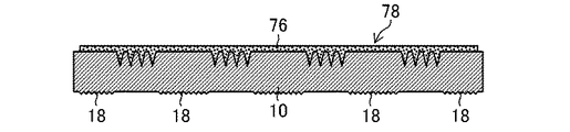
図22は、薬剤が含有したポリマー溶解液60の上に、薬剤を含まないポリマー溶解液76を塗布し、これらのポリマー溶解液60、76を乾燥させてパターンシート78に成形する乾燥工程(S30)が示されている。乾燥工程(S30)では、モールド10に供給されたポリマー溶解液60、76に風を吹付けることによりポリマー溶解液60、76を乾燥させる。これによって、パターンシート78がモールド10によって製造される。
FIG. 22 shows a drying step (S30) in which a
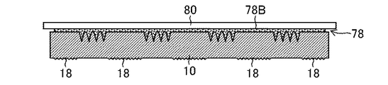
図23及び図24は、パターンシート78をモールド10から剥離するパターンシート剥離工程(S40)が示されている。剥離工程では、図23に示すように、パターンシート78の裏面78Bに、シート状の基材80を貼付してもよい。基材80としては、例えば、PET(polyethylene terephthalate:ポリエチレンテレフタレート)、PP(polypropylene:ポリプロピレン)、PC(polycarbonate:ポリカーボネート)、PE(Polyethylene:ポリエチレン)等を使用することができる。
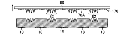
23 and 24 show a pattern sheet peeling step (S40) for peeling the
次に、図24に示すように、基材80とパターンシート78とを同時にモールド10から剥離する。これにより、複数の突起状パターン82が、その表面78Aにアレイ状に配置されたパターンシート78を製造することができる。パターンシート78の突起状パターン82は、モールド10の凹状パターン16の反転形状となる。
Next, as shown in FIG. 24, the
図25及び図26は、パターンシート78を突起状パターン82ごと切断してMNA84を得る切断工程(S50)が示されている。
25 and 26 show a cutting step (S50) in which the
図25に示すように、モールド10から剥離したパターンシート78と基材80とを切断装置(不図示)にセットして、突起状パターン82ごと切断し、複数のMNA84を得る。なお、実施形態では、パターンシート78と基材80とを同時に切断する例を示したが、これに限定されない。例えば、モールド10から剥離したパターンシート78と基材80とから、基材80を剥離し、パターンシート78を切断することによりMNA84を得てもよい。
As shown in FIG. 25, the
本発明は、上記の好ましい実施形態により説明したが、本発明の範囲を逸脱すること無く、多くの手法により変更を行うことができ、実施形態以外の他の実施形態を利用することができる。したがって、本発明の範囲内における全ての変更が特許請求の範囲に含まれる。 Although the present invention has been described with reference to the above-described preferred embodiments, modifications can be made by many techniques without departing from the scope of the present invention, and other embodiments than the embodiments can be used. Accordingly, all modifications within the scope of the present invention are included in the claims.
10…モールド
12…シート
12A…表面
12B…裏面
14…凹部
16…凹状パターン
18…凹凸部
20…配置領域
22…領域
22A…領域面
24…非配置領域
26…領域
26A…配置領域面
30…電鋳金型
32…モールド
32A…凹状パターン
34…原版
34A…突起状パターン
34B…表面
36…突起部
38…熱可塑性樹脂シート
38B…表面
38C…裏面
38D…針状凹部
40…金属体
42…金型
44…キャビティ
46…シリコーンゴム
48…下型
50…上型
52…凹凸部
54…検査装置
60…ポリマー溶解液
60a…液面
62…光源
64…光学系
66…透明ガラス基板
68…結像レンズ
70…撮像部
72…撮像ユニット
74…解析部
76…ポリマー溶解液
78…パターンシート
80…基材
82…突起状パターン
84…MNA
DESCRIPTION OF
Claims (7)
前記シートの裏面の一部に凹凸部が配置される、モールド。 In the mold in which concave patterns consisting of a plurality of concave portions are arranged in an array on the surface of the sheet,
A mold in which a concavo-convex portion is arranged on a part of the back surface of the sheet.
前記シートの表面の前記凹状パターンの非配置領域に対向する、前記シートの裏面の領域に前記凹凸部が配置される、請求項1又は2に記載のモールド。 The area of the back surface of the sheet facing the arrangement area of the concave pattern on the surface of the sheet is a flat surface,
3. The mold according to claim 1, wherein the uneven portion is disposed in a region of the back surface of the sheet facing a non-arranged region of the concave pattern on the surface of the sheet.
前記モールドのシートの表面に配置された凹状パターンにポリマー溶解液を供給する供給工程と、
前記モールドの前記シートの裏面を検査台に載置して前記凹状パターンに供給された前記ポリマー溶解液の供給量を検査する検査工程と、
前記ポリマー溶解液を乾燥させてパターンシートに成形する乾燥工程と、
前記パターンシートを前記モールドから剥離するパターンシート剥離工程と、
を含むパターンシートの製造方法。 Use the mold according to any one of claims 1 to 6,
A supply step of supplying a polymer solution to the concave pattern disposed on the surface of the sheet of the mold;
An inspection step of inspecting the supply amount of the polymer solution supplied to the concave pattern by placing the back surface of the sheet of the mold on an inspection table;
A drying step of drying the polymer solution to form a pattern sheet;
A pattern sheet peeling step for peeling the pattern sheet from the mold;
The manufacturing method of the pattern sheet containing this.
Priority Applications (1)
| Application Number | Priority Date | Filing Date | Title |
|---|---|---|---|
| JP2016097826A JP6537072B2 (en) | 2016-05-16 | 2016-05-16 | Mold and pattern sheet manufacturing method |
Applications Claiming Priority (1)
| Application Number | Priority Date | Filing Date | Title |
|---|---|---|---|
| JP2016097826A JP6537072B2 (en) | 2016-05-16 | 2016-05-16 | Mold and pattern sheet manufacturing method |
Publications (3)
| Publication Number | Publication Date |
|---|---|
| JP2017205152A true JP2017205152A (en) | 2017-11-24 |
| JP2017205152A5 JP2017205152A5 (en) | 2018-09-20 |
| JP6537072B2 JP6537072B2 (en) | 2019-07-03 |
Family
ID=60414644
Family Applications (1)
| Application Number | Title | Priority Date | Filing Date |
|---|---|---|---|
| JP2016097826A Expired - Fee Related JP6537072B2 (en) | 2016-05-16 | 2016-05-16 | Mold and pattern sheet manufacturing method |
Country Status (1)
| Country | Link |
|---|---|
| JP (1) | JP6537072B2 (en) |
Citations (5)
| Publication number | Priority date | Publication date | Assignee | Title |
|---|---|---|---|---|
| JP2005215614A (en) * | 2004-02-02 | 2005-08-11 | Alps Electric Co Ltd | Method for manufacturing reflector |
| JP2011224332A (en) * | 2010-03-29 | 2011-11-10 | Fujifilm Corp | Skin absorption sheet and method for manufacturing the same |
| US20140343499A1 (en) * | 2011-11-30 | 2014-11-20 | 3M Innovative Properties Company | Microneedle device including a peptide therapeutic agent and an amino acid and methods of making and using the same |
| JP2015217043A (en) * | 2014-05-15 | 2015-12-07 | 富士フイルム株式会社 | Transdermal absorption sheet and method of manufacturing transdermal absorption sheet |
| JP2016179093A (en) * | 2015-03-24 | 2016-10-13 | 富士フイルム株式会社 | Measuring method, measuring apparatus and program |
-
2016
- 2016-05-16 JP JP2016097826A patent/JP6537072B2/en not_active Expired - Fee Related
Patent Citations (5)
| Publication number | Priority date | Publication date | Assignee | Title |
|---|---|---|---|---|
| JP2005215614A (en) * | 2004-02-02 | 2005-08-11 | Alps Electric Co Ltd | Method for manufacturing reflector |
| JP2011224332A (en) * | 2010-03-29 | 2011-11-10 | Fujifilm Corp | Skin absorption sheet and method for manufacturing the same |
| US20140343499A1 (en) * | 2011-11-30 | 2014-11-20 | 3M Innovative Properties Company | Microneedle device including a peptide therapeutic agent and an amino acid and methods of making and using the same |
| JP2015217043A (en) * | 2014-05-15 | 2015-12-07 | 富士フイルム株式会社 | Transdermal absorption sheet and method of manufacturing transdermal absorption sheet |
| JP2016179093A (en) * | 2015-03-24 | 2016-10-13 | 富士フイルム株式会社 | Measuring method, measuring apparatus and program |
Also Published As
| Publication number | Publication date |
|---|---|
| JP6537072B2 (en) | 2019-07-03 |
Similar Documents
| Publication | Publication Date | Title |
|---|---|---|
| JP6495465B2 (en) | Method for producing mold, method for producing pattern sheet, method for producing electroformed mold, and method for producing mold using electroformed mold | |
| US10814527B2 (en) | Method of producing transdermal absorption sheet | |
| US20180250851A1 (en) | Manufacturing method of pattern sheet | |
| JPWO2014077242A1 (en) | Method for producing transdermal absorption sheet | |
| US10441532B2 (en) | Method of producing transdermal absorption sheet | |
| US10195768B2 (en) | Method of manufacturing mold and method of manufacturing pattern sheet | |
| CN111660468A (en) | Method for manufacturing mold having concave pattern in concave step portion and method for manufacturing pattern sheet | |
| US10814118B2 (en) | Transdermal absorption sheet | |
| US10596361B2 (en) | Transdermal absorption sheet and method of producing the same | |
| JP6571586B2 (en) | Method for producing mold, method for producing pattern sheet, method for producing electroformed mold, and method for producing mold using electroformed mold | |
| JP6533189B2 (en) | Method of manufacturing mold for pattern array sheet, and method of manufacturing microneedle array | |
| EP3153291B1 (en) | Method of manufacturing mold and method of manufacturing pattern sheet | |
| CN112839698B (en) | Method for producing percutaneous absorption sheet | |
| JP2017209157A (en) | Mold, mold manufacturing method, and pattern sheet manufacturing method | |
| WO2019225288A1 (en) | Method for manufacturing mold having recessed pattern in recessed step part, and method for producing pattern sheet | |
| JP6537072B2 (en) | Mold and pattern sheet manufacturing method | |
| JP2018042677A (en) | Concave pattern mold and pattern sheet manufacturing method |
Legal Events
| Date | Code | Title | Description |
|---|---|---|---|
| A621 | Written request for application examination |
Free format text: JAPANESE INTERMEDIATE CODE: A621 Effective date: 20180806 |
|
| A521 | Request for written amendment filed |
Free format text: JAPANESE INTERMEDIATE CODE: A523 Effective date: 20180807 |
|
| A977 | Report on retrieval |
Free format text: JAPANESE INTERMEDIATE CODE: A971007 Effective date: 20190412 |
|
| A131 | Notification of reasons for refusal |
Free format text: JAPANESE INTERMEDIATE CODE: A131 Effective date: 20190418 |
|
| A521 | Request for written amendment filed |
Free format text: JAPANESE INTERMEDIATE CODE: A523 Effective date: 20190517 |
|
| TRDD | Decision of grant or rejection written | ||
| A01 | Written decision to grant a patent or to grant a registration (utility model) |
Free format text: JAPANESE INTERMEDIATE CODE: A01 Effective date: 20190529 |
|
| A61 | First payment of annual fees (during grant procedure) |
Free format text: JAPANESE INTERMEDIATE CODE: A61 Effective date: 20190529 |
|
| R150 | Certificate of patent or registration of utility model |
Ref document number: 6537072 Country of ref document: JP Free format text: JAPANESE INTERMEDIATE CODE: R150 |
|
| LAPS | Cancellation because of no payment of annual fees |