JP2017205805A - Method and system to use combination of filler wire feed and high intensity energy source for welding and arc suppression of variable polarity hot-wire - Google Patents
Method and system to use combination of filler wire feed and high intensity energy source for welding and arc suppression of variable polarity hot-wire Download PDFInfo
- Publication number
- JP2017205805A JP2017205805A JP2017091075A JP2017091075A JP2017205805A JP 2017205805 A JP2017205805 A JP 2017205805A JP 2017091075 A JP2017091075 A JP 2017091075A JP 2017091075 A JP2017091075 A JP 2017091075A JP 2017205805 A JP2017205805 A JP 2017205805A
- Authority
- JP
- Japan
- Prior art keywords
- welding
- hot wire
- waveform
- current
- pulse portion
- Prior art date
- Legal status (The legal status is an assumption and is not a legal conclusion. Google has not performed a legal analysis and makes no representation as to the accuracy of the status listed.)
- Ceased
Links
Images






Classifications
-
- B—PERFORMING OPERATIONS; TRANSPORTING
- B23—MACHINE TOOLS; METAL-WORKING NOT OTHERWISE PROVIDED FOR
- B23K—SOLDERING OR UNSOLDERING; WELDING; CLADDING OR PLATING BY SOLDERING OR WELDING; CUTTING BY APPLYING HEAT LOCALLY, e.g. FLAME CUTTING; WORKING BY LASER BEAM
- B23K9/00—Arc welding or cutting
- B23K9/09—Arrangements or circuits for arc welding with pulsed current or voltage
- B23K9/091—Arrangements or circuits for arc welding with pulsed current or voltage characterised by the circuits
- B23K9/092—Arrangements or circuits for arc welding with pulsed current or voltage characterised by the circuits characterised by the shape of the pulses produced
-
- B—PERFORMING OPERATIONS; TRANSPORTING
- B23—MACHINE TOOLS; METAL-WORKING NOT OTHERWISE PROVIDED FOR
- B23K—SOLDERING OR UNSOLDERING; WELDING; CLADDING OR PLATING BY SOLDERING OR WELDING; CUTTING BY APPLYING HEAT LOCALLY, e.g. FLAME CUTTING; WORKING BY LASER BEAM
- B23K26/00—Working by laser beam, e.g. welding, cutting or boring
- B23K26/20—Bonding
- B23K26/21—Bonding by welding
-
- B—PERFORMING OPERATIONS; TRANSPORTING
- B23—MACHINE TOOLS; METAL-WORKING NOT OTHERWISE PROVIDED FOR
- B23K—SOLDERING OR UNSOLDERING; WELDING; CLADDING OR PLATING BY SOLDERING OR WELDING; CUTTING BY APPLYING HEAT LOCALLY, e.g. FLAME CUTTING; WORKING BY LASER BEAM
- B23K9/00—Arc welding or cutting
- B23K9/09—Arrangements or circuits for arc welding with pulsed current or voltage
- B23K9/091—Arrangements or circuits for arc welding with pulsed current or voltage characterised by the circuits
-
- B—PERFORMING OPERATIONS; TRANSPORTING
- B23—MACHINE TOOLS; METAL-WORKING NOT OTHERWISE PROVIDED FOR
- B23K—SOLDERING OR UNSOLDERING; WELDING; CLADDING OR PLATING BY SOLDERING OR WELDING; CUTTING BY APPLYING HEAT LOCALLY, e.g. FLAME CUTTING; WORKING BY LASER BEAM
- B23K26/00—Working by laser beam, e.g. welding, cutting or boring
- B23K26/34—Laser welding for purposes other than joining
- B23K26/342—Build-up welding
-
- B—PERFORMING OPERATIONS; TRANSPORTING
- B23—MACHINE TOOLS; METAL-WORKING NOT OTHERWISE PROVIDED FOR
- B23K—SOLDERING OR UNSOLDERING; WELDING; CLADDING OR PLATING BY SOLDERING OR WELDING; CUTTING BY APPLYING HEAT LOCALLY, e.g. FLAME CUTTING; WORKING BY LASER BEAM
- B23K26/00—Working by laser beam, e.g. welding, cutting or boring
- B23K26/70—Auxiliary operations or equipment
- B23K26/702—Auxiliary equipment
-
- B—PERFORMING OPERATIONS; TRANSPORTING
- B23—MACHINE TOOLS; METAL-WORKING NOT OTHERWISE PROVIDED FOR
- B23K—SOLDERING OR UNSOLDERING; WELDING; CLADDING OR PLATING BY SOLDERING OR WELDING; CUTTING BY APPLYING HEAT LOCALLY, e.g. FLAME CUTTING; WORKING BY LASER BEAM
- B23K9/00—Arc welding or cutting
- B23K9/04—Welding for other purposes than joining, e.g. built-up welding
- B23K9/042—Built-up welding on planar surfaces
-
- B—PERFORMING OPERATIONS; TRANSPORTING
- B23—MACHINE TOOLS; METAL-WORKING NOT OTHERWISE PROVIDED FOR
- B23K—SOLDERING OR UNSOLDERING; WELDING; CLADDING OR PLATING BY SOLDERING OR WELDING; CUTTING BY APPLYING HEAT LOCALLY, e.g. FLAME CUTTING; WORKING BY LASER BEAM
- B23K9/00—Arc welding or cutting
- B23K9/06—Arrangements or circuits for starting the arc, e.g. by generating ignition voltage, or for stabilising the arc
- B23K9/073—Stabilising the arc
-
- B—PERFORMING OPERATIONS; TRANSPORTING
- B23—MACHINE TOOLS; METAL-WORKING NOT OTHERWISE PROVIDED FOR
- B23K—SOLDERING OR UNSOLDERING; WELDING; CLADDING OR PLATING BY SOLDERING OR WELDING; CUTTING BY APPLYING HEAT LOCALLY, e.g. FLAME CUTTING; WORKING BY LASER BEAM
- B23K9/00—Arc welding or cutting
- B23K9/10—Other electric circuits therefor; Protective circuits; Remote controls
- B23K9/1006—Power supply
- B23K9/1043—Power supply characterised by the electric circuit
- B23K9/1056—Power supply characterised by the electric circuit by using digital means
-
- B—PERFORMING OPERATIONS; TRANSPORTING
- B23—MACHINE TOOLS; METAL-WORKING NOT OTHERWISE PROVIDED FOR
- B23K—SOLDERING OR UNSOLDERING; WELDING; CLADDING OR PLATING BY SOLDERING OR WELDING; CUTTING BY APPLYING HEAT LOCALLY, e.g. FLAME CUTTING; WORKING BY LASER BEAM
- B23K9/00—Arc welding or cutting
- B23K9/10—Other electric circuits therefor; Protective circuits; Remote controls
- B23K9/1093—Consumable electrode or filler wire preheat circuits
-
- B—PERFORMING OPERATIONS; TRANSPORTING
- B23—MACHINE TOOLS; METAL-WORKING NOT OTHERWISE PROVIDED FOR
- B23K—SOLDERING OR UNSOLDERING; WELDING; CLADDING OR PLATING BY SOLDERING OR WELDING; CUTTING BY APPLYING HEAT LOCALLY, e.g. FLAME CUTTING; WORKING BY LASER BEAM
- B23K9/00—Arc welding or cutting
- B23K9/12—Automatic feeding or moving of electrodes or work for spot or seam welding or cutting
- B23K9/124—Circuits or methods for feeding welding wire
Landscapes
- Engineering & Computer Science (AREA)
- Physics & Mathematics (AREA)
- Plasma & Fusion (AREA)
- Mechanical Engineering (AREA)
- Optics & Photonics (AREA)
- Arc Welding In General (AREA)
- Arc Welding Control (AREA)
Abstract
【課題】 可変極性ホットワイヤの溶接および消弧のためのフィラワイヤ送給と高強度エネルギー源の組合せを使用する方法およびシステムを提供する。
【解決手段】 本発明の方法およびシステムは、アーク溶接システムと共に使用されるホットワイヤ溶接システムに関し、溶接システムはホットワイヤ溶接システム内でアーク遮断ルーチンを開始する。アーク遮断ルーチンは、アークを検出し、その後、ホットワイヤ波形のフルパルスをスキップするステップと、次のパルスを開始して、消耗材が依然として分離しているか否かを判断するステップとを含む。後続パルスは、消耗材が分離しなくなったと判断されるまで繰り返し開始され、その時、ホットワイヤ作業が継続される。
【選択図】なしPROBLEM TO BE SOLVED: To provide a method and system using a combination of filler wire feed and high intensity energy source for welding and arc extinction of variable polarity hot wires.
The method and system of the present invention relates to a hot wire welding system for use with an arc welding system, where the welding system initiates an arc interruption routine within the hot wire welding system. The arc interrupt routine includes detecting an arc and then skipping a full pulse of the hot wire waveform and starting the next pulse to determine if the consumables are still separated. Subsequent pulses are repeated until it is determined that the consumables are no longer separated, at which time the hot wire operation continues.
[Selection figure] None
Description
優先権
本願は、2016年5月17日に出願された米国仮特許出願第62/337,821号明細書の優先権を主張するものであり、同仮出願の全体を参照によって本願に援用する。
This application claims the priority of US Provisional Patent Application No. 62 / 337,821 filed on May 17, 2016, which is incorporated herein by reference in its entirety. .
特定の実施形態はフィラワイヤ添加の利用のほか、溶接および接合の利用に関する。より詳しくは、特定の実施形態は、レーザまたはアーク溶接工程によるホットワイヤ溶着工程を利用するシステムおよび方法、ならびに可変極性ホットワイヤ作業中の消弧に関する。 Particular embodiments relate to the use of filler wire addition as well as the use of welding and joining. More particularly, certain embodiments relate to systems and methods that utilize hot wire welding processes by laser or arc welding processes, and arc extinction during variable polarity hot wire operations.
近年、ホットワイヤ溶接が進化を遂げている。しかしながら、これらの工程とシステムの中には、隣接するアーク溶接プロセスにより生成されるアークを干渉しうる電流波形を利用するものがある。さらに、特定の用途では溶融池の混合と撹拌が追加で必要となるかもしれず、これは、いくつかの既知の工程では実現できないかもしれない。さらに、可変極性波形を使用するいくつかのホットワイヤの用途において、特定の消弧技術がホットワイヤ工程の動作を不利に干渉しうることがわかった。 In recent years, hot wire welding has evolved. However, some of these processes and systems make use of current waveforms that can interfere with arcs generated by adjacent arc welding processes. In addition, certain applications may require additional mixing and agitation of the molten pool, which may not be possible with some known processes. Furthermore, it has been found that in some hot wire applications that use variable polarity waveforms, certain arc extinguishing techniques can adversely interfere with the operation of the hot wire process.
従来の、伝統的な、および提案中の方式のその他の限界と欠点は、本願の残りの部分に図面に関して記載されている、このような方式と本発明の実施形態との比較を通じて、当業者にとって明らかとなるであろう。 Other limitations and disadvantages of conventional, traditional and proposed schemes are described in the remainder of this application with reference to the drawings, and will be understood by those skilled in the art through comparison of such schemes with embodiments of the present invention. It will be clear to you.
本発明の実施形態は、ホットワイヤ溶着工程を用いるクラッディング、肉盛、接合、または溶接のための、ホットワイヤ波形がタンデムアーク溶接波形と同期されるシステムと方法を含む。本明細書に記載されているシステムと方法の別の実施形態は、可変極性ホットワイヤ溶着作業における消弧技術に関する。 Embodiments of the present invention include systems and methods in which a hot wire waveform is synchronized with a tandem arc welding waveform for cladding, overlaying, joining, or welding using a hot wire welding process. Another embodiment of the systems and methods described herein relates to arc extinguishing techniques in variable polarity hot wire welding operations.
特許請求される発明のこれらおよびそれ以外の特徴と、例示されているその実施形態の詳細は、以下の説明と図面から、より十分に理解されるであろう。 These and other features of the claimed invention, as well as details of the illustrated embodiments, will be more fully understood from the following description and drawings.
本発明の上記および/またはその他の態様は、下記のような添付の図面を参照しながら本発明の例示的実施形態を詳しく説明することによって、より明らかとなるであろう。 These and / or other aspects of the invention will become more apparent from the detailed description of exemplary embodiments of the invention with reference to the accompanying drawings, in which:
ここで、本発明の例示的実施形態を添付の図面に関して以下に説明する。説明されている例示的実施形態は、発明の理解を助けるためのものであり、本発明の範囲を如何様にも限定しようとしていない。図面全体を通じて、同様の参照番号は同様の要素を指す。 Exemplary embodiments of the present invention will now be described below with reference to the accompanying drawings. The described exemplary embodiments are intended to aid the understanding of the invention and are not intended to limit the scope of the invention in any way. Like reference numerals refer to like elements throughout the drawings.
図1は、ろう付け、クラッディング、構築、充填、表面硬化肉盛、および接合/溶接利用の何れかを実行するためのフィラワイヤ送給およびエネルギー源複合システム100のある例示的実施形態の機能概略ブロック図を示す。システム100は、レーザビーム110を被加工物115に集光して、被加工物115を加熱することのできるレーザサブシステムを含む。レーザサブシステムは、高強度エネルギー源である。レーザサブシステムは、何れの種類の高エネルギーレーザ源とすることもでき、これには二酸化炭素、Nd:YAG、Yb−ディスク、YB−ファイバ、ファイバ伝送、またはダイレクトダイオードレーザシステムが含まれるが、これらに限定されない。さらに、その他の種類のレーザシステムも、十分なエネルギーを持っていれば使用できる。システムの他の実施形態は、電子ビーム、プラズマアーク溶接サブシステム、ティグ溶接(gas tungsten arc welding)サブシステム、ガスメタルアーク溶接サブシステム、フラックス入りワイヤアーク溶接サブシステム、およびサブマージワイヤアークサブシステムのうちの少なくとも1つを高強度エネルギー源として含んでいてもよい。以下の説明では、レーザシステム、ビーム、および電源に繰り返し言及するが、何れの高強度エネルギー源が使用されてもよいため、この言及は例にすぎないと理解すべきである。例えば、高強度エネルギー源は少なくとも500W/cm2を供給できる。レーザサブシステムは、レーザ装置120と、レーザ電源130と、を含み、これらは相互に動作的に接続されている。レーザ電源130は、レーザ装置120を動作させるための電源を供給する。
FIG. 1 is a functional overview of an exemplary embodiment of a combined filler wire delivery and
システム100はまた、ホットワイヤ送給サブシステムも含み、これは被加工物115とレーザビーム110の付近で接触するための少なくとも1つの抵抗フィラワイヤ140を送給できる。もちろん、本明細書中で被加工物115に言及することにより、溶融池が被加工物115の一部と考えられ、それゆえ、被加工物115との接触という場合、溶融池との接触も含まれると理解する。ホットフィラワイヤ送給サブシステムは、フィラワイヤ送給器150と、コンタクトチップ160と、ホットワイヤ電源170と、を含む。動作中、レーザビーム110に先行するフィラワイヤ140は、コンタクトチップ160と被加工物115との間に動作的に接続されたホットワイヤ溶接電源170からの電流により抵抗加熱される。本発明のある実施形態によれば、ホットワイヤ溶接電源170は、パルス式直流(DC)電源であるが、交流電流(AC)またはその他の種類の電源も使用可能である。ワイヤ140は、フィラワイヤ送給器150からコンタクトチップ160を通って被加工物115へと送給され、チップ160から突き出す。ワイヤ140の突出し部分は、突出し部分が融点に近付くか、到達してから被加工物上の溶融池と接触するように抵抗加熱される。レーザビーム110は、被加工物115の母材の一部を溶融させて、溶融池を形成するほか、ワイヤ140を被加工物115の上へと溶融させる役割を果たす。電源170は、フィラワイヤ140を抵抗溶融させるのに必要なエネルギーの大部分を供給する。送給サブシステムは、本発明の特定の他の実施形態によれば、1本または複数のワイヤを同時に送給できてもよい。例えば、第一のワイヤは被加工物に表面硬化および/または耐食性を提供するために使用されてもよく、第二のワイヤは被加工物に構造を追加するために使用されてもよい。
The
システム100は運動制御サブシステムをさらに含み、これはレーザビーム110(エネルギー源)と抵抗フィラワイヤ140を被加工物115に沿って同じ方向に(少なくとも相対的意味で)移動させ、レーザビーム110と抵抗フィラワイヤ140が相互に関して固定されたままとなるようにすることができる。各種の実施形態によれば、被加工物115とレーザ/ワイヤの組合せとの間の相対的移動は、被加工物115を実際に移動させることによって、またはレーザ装置120とホットワイヤ送給サブシステムを移動させることによって実現されてもよい。図1において、運動制御サブシステムはロボット190に動作的に接続されたモーションコントローラ180を含む。モーションコントローラ180は、ロボット190の動きを制御する。ロボット190は、被加工物115に動作的に接続され(例えば、機械的に固定され)、被加工物115を方向125に移動させて、レーザビーム110とワイヤ140が被加工物115に沿って有効に移動できるようにする。本発明の代替的な実施形態によれば、レーザ装置110とコンタクトチップ160は、1つのヘッドに統合されてもよい。ヘッドは、被加工物115に沿って、ヘッドに動作的に接続された運動制御サブシステムを介して移動されてもよい。
The
一般に、高強度エネルギー源/ホットワイヤを被加工物に関して移動させることのできるいくつかの方法がある。例えば、被加工物が丸い場合、高強度エネルギー源/ホットワイヤを静止させて、被加工物を高強度エネルギー源/ホットワイヤの下方で回転させてもよい。あるいは、ロボットアームまたはリニアトラクタが丸い被加工物に平行に移動されてもよく、被加工物を回転させながら、高強度エネルギー源/ホットワイヤを連続的に、または例えば1回転に1段階ずつ移動させて、丸い被加工物の表面に重なるようにしてもよい。被加工物が平坦か、少なくとも丸くない場合、被加工物は、図1に示されるように、高強度エネルギー源/ホットワイヤの下方で移動させてもよい。しかしながら、ロボットアームもしくはリニアトラクタまたは、さらにはビーム取付型キャリッジを使って、高強度エネルギー源/ホットワイヤヘッドを被加工物に関して移動させてもよい。 In general, there are several ways in which the high intensity energy source / hot wire can be moved relative to the workpiece. For example, if the workpiece is round, the high intensity energy source / hot wire may be stationary and the workpiece may be rotated below the high intensity energy source / hot wire. Alternatively, the robot arm or linear tractor may be moved parallel to the round workpiece, moving the high-strength energy source / hot wire continuously or, for example, one step per rotation while rotating the workpiece And may overlap the surface of the round workpiece. If the work piece is flat or at least not round, the work piece may be moved below the high intensity energy source / hot wire as shown in FIG. However, a high intensity energy source / hot wire head may be moved with respect to the workpiece using a robot arm or linear tractor or even a beam mounted carriage.
システム100は、検出および電流制御サブシステム195をさらに含み、これは被加工物115およびコンタクトチップ160に動作的に接続され(すなわち、ホットワイヤ電源170の出力に有効に接続され)、被加工物115とホットワイヤ140との間の電位差(すなわち、電圧V)とそれらを流れる電流(I)を測定することができる。検出および電流制御サブシステム195はさらに、測定された電圧と電流から抵抗値(R=V/I)および/または出力値(P=V*I)を計算することができてもよい。一般に、ホットワイヤ140が被加工物115と接触していると、ホットワイヤ140と被加工物115との間の電位差はゼロボルトであるか、ゼロボルトに非常に近い。その結果、検出および電流制御サブシステム195は、抵抗フィラワイヤ140が被加工物115といつ接触して、ホットワイヤ電源170に動作的に接続されたかを検出でき、その検出に応答して、本明細書で後により詳しく説明するように、抵抗フィラワイヤ140を通る電流の流れを制御することがさらに可能である。本発明の他の実施形態によれば、検出および電流コントローラ195は、ホットワイヤ電源170の一体部分であってもよい。
本発明のある実施形態によれば、モーションコントローラ180はさらに、レーザ電源130および/または検出および電流コントローラ195に動作的に接続されてもよい。このようにして、モーションコントローラ180とレーザ電源130は相互に通信して、被加工物115がいつ移動しているかがレーザ電源130にわかり、またレーザ装置120が動作中か否かがモーションコントローラ180にわかるようになっていてもよい。同様に、このようにして、モーションコントローラ180と検出および電流コントローラ195は相互に通信して、被加工物115が移動中であることが検出および電流コントローラ195にわかり、また、ホットフィラワイヤ送給サブシステムが動作中であるか否かがモーションコントローラ180にわかるようになっていてもよい。このような通信を使用して、システム100の様々なサブシステム間の動作が調整されてもよい。
According to certain embodiments of the present invention,
前述のように、高強度エネルギー源は溶接電源を含め、いくつのエネルギー源を含むこともできる。この例示的実施形態が図2に示されており、これは、図1に示されるシステム100と同様のシステム200を示している。システム200の構成要素の多くがシステム100の構成要素と同様であり、そのため、それらの動作と利用について、再び詳しく説明することはしない。しかしながら、システム200においては、レーザシステムがアーク溶接システム、例えばGMAWシステムに置き換えられている。GMAWシステムは、電源213と、ワイヤ送給器215と、トーチ212と、を含む。溶接電極211は、ワイヤ送給器215とトーチ212を介して溶融池へと送達される。ここで説明される種類のGMAW溶接システムの動作はよく知られており、ここで詳しく説明する必要はない。留意すべき点として、図の例示的実施形態に関してはGMAWシステムが示され、論じられているが、本発明の例示的実氏形態はGTAW、FCAW、MCAW、およびSAWシステム、クラッディングシステム、ろう付けシステム、およびこれらのシステムの組合せ、その他、例えば被加工物上の溶融池に消耗材を搬送するのを支援するためにアークを使用するシステムを含め、何れにも使用可能である。図2には、シールドガスシステムまたはサブアークフラックスシステムは示されておらず、これらは既知の方法に従って使用可能である。
As described above, the high intensity energy source can include any number of energy sources, including a welding power source. This exemplary embodiment is shown in FIG. 2, which shows a
上述のレーザシステムと同様に、アーク生成システム(高強度エネルギー源として使用可能)は溶融池を作るのに使用され、そこにホットワイヤ140が、詳しく上述したようなシステムと実施形態を使って添加される。しかしながら、アーク生成システムを用いると、既知のように、追加の消耗材211もまた溶融池に添加される。この追加の消耗材により、本明細書で説明するホットワイヤ工程によって既に高められた溶着性能がさらに高まる。この性能については、後で詳しく説明する。
Similar to the laser system described above, an arc generation system (which can be used as a high-intensity energy source) is used to create a molten pool, to which a
さらに、一般に知られているように、GMAW等のアーク生成システムは高レベルの電流を使って、前進させられている消耗材と被加工物上の溶融池との間にアークを生成する。同様に、GTAWシステムも高い電流レベルを使って電極と被加工物との間にアークを生成し、そこに消耗材が添加される。一般に知られているように、定電流、パルス電流等、様々な電流波形をGTAWまたはGMAW溶接作業に利用できる。しかしながら、システム200の動作中、電源213により生成される電流は、ワイヤ140の加熱に使用される、電源170により生成される電流を干渉する可能性がある。ワイヤ140は電源213により生成されるアークに近接しているため(これらの各々が上述のものと同様に、同じ溶融池に向けられるからである)、それぞれの電流が相互に干渉し合う可能性がある。具体的には、電流の各々は磁場を生じさせ、これらの磁場が相互に干渉して、それらの動作に不利な影響を与える可能性がある。例えば、ホットワイヤ電流により発生された磁場は、電源213により生成されたアークの安定性と干渉しうる。すなわち、それぞれの電流間を適切に管理し、同期させなければ、競合する磁場がアークを不安定にし、したがって、工程が不安定となる可能性がある。したがって、例示的実施形態は電源213および170間の電流同期を利用して安定した動作を確保するものであり、これにいては後でさらに説明する。
Further, as is generally known, arc generation systems such as GMAW use a high level of current to generate an arc between the consumable material being advanced and the molten pool on the workpiece. Similarly, GTAW systems use high current levels to create an arc between the electrode and the workpiece, to which consumable material is added. As is generally known, various current waveforms such as constant current and pulse current can be used for GTAW or GMAW welding operations. However, during operation of the
前述のように、それぞれの電流により誘導される磁場は相互に干渉しあうため、本発明の実施形態はそれぞれの電流を同期させる。同期は、様々な方法で実現できる。例えば、検出および電流コントローラ195は、電源213および170の動作を制御して、電流を同期させるために使用できる。あるいは、マスタ−スレーブ関係もまた利用でき、この場合、電源のうちの一方が他方の出力の制御に使用される。相対的電流の制御は、電源を、それらの出力電流が安定した動作のために同期されるように制御する状態テーブルまたはアルゴリズムの使用を含む、様々な方法により実現できる。これについては、後でさらに説明する。例えば、(特許文献1)に記載されているものと同様の2状態に基づくシステムと装置を使用できる。2010年4月22日に公開された(特許文献1)の全体を参照によって本願に援用する。
As described above, since the magnetic fields induced by the respective currents interfere with each other, embodiments of the present invention synchronize the respective currents. Synchronization can be achieved in various ways. For example, the detection and
システム100および200の構造、使用、制御、度動作、および機能に関するより詳しい説明は、本願と同じ所有者に譲渡されている(特許文献2)および(特許文献3)に記載されており、本明細書において説明され、論じられているシステムおよび本明細書に論じられている代替的実施形態に関するかぎり、それらの全体を参照によって本願に完全に援用し、これらについては、効率化と明瞭化のためにここでは反復しない。
A more detailed description of the structure, use, control, degree of operation, and function of the
図3は、本発明のシステム300の他の例示的実施形態の略図を示す。システム200と同様に、システム300はホットワイヤおよびアーク溶接の複合工程を利用する。システム300の機能および動作は、システム200のそれと同様であり、そのため、同様の機能については繰り返さない。図のように、システム300は先行のアーク溶接電源301を含み、これは後行のホットワイヤ140に先行する。電源301はGMAW型電源として示されているが、GTAW型電源も利用できるため、実施形態はこれに限定されない。溶接電源301は、何れの既知の構成とすることもできる。また、ホットワイヤ電源301(これは、図1および2に示されているものと同じとすることができる)も、その中の構成要素の一部と共に示されている。前述のように、電源301および310の各々から出力される電流波形を同期させることが望ましいかもしれない。そのため、同期信号303を利用して、電源の動作を確実に同期させることができ、これについては後でさらに説明する。
FIG. 3 shows a schematic diagram of another exemplary embodiment of the
ホットワイヤ電源310はインバータ電源部311を含み、これは入力電力(ACまたはDCの何れでもよい)を受け取り、この入力電力を出力電力に変換し、それがワイヤ140を加熱するために使用され、それによってこれは被加工物Wの上の溶融池の中に溶着できる。インバータ電源部311は、溶接、切断、またはホットワイヤ電源に使用される何れの既知のインバータ型電源として構成することもできる。電源はまた、事前設定加熱電圧回路313も含み、これは工程に関する入力データを利用して、電源310の出力信号のための事前設定加熱電圧を設定し、ワイヤ140が所望の温度に保持されて、それが被加工物Wの上に適正に溶着されるようにする。例えば、事前設定加熱電圧回路313は、ワイヤのサイズ、ワイヤの種類、およびワイヤ送給速度等の設定を利用して、事前設定加熱電圧が工程中に保持されるようにすることができる。動作中、出力加熱信号が保持され、それによって所定の期間またはサイクル数にわたる平均電圧が事前設定加熱電圧レベルに保持される。いくつかの実施形態において、事前設定加熱電圧レベルは2〜9ボルトの範囲内である。さらに、本発明の例示的実施形態において、ワイヤ140のワイヤ送給速度は最適な事前設定加熱電圧レベルに影響を与える可能性があり、その結果、ワイヤ送給速度が遅いと(200in/分以下)、事前設定加熱電圧レベルは2〜4ボルトの範囲内であり、ワイヤ送給速度が高いと(200in/分を超える)、事前設定加熱電圧レベルは5〜9ボルトの範囲内である。さらに、いくつかの例示的実施形態において、電流が低いと(150アンペア以下)であると事前設定加熱電圧レベルは2〜4ボルトの範囲内であり、電流が高いと(150アンペアを超える)と、事前設定加熱電圧レベルは5〜9ボルトの範囲内である。それゆえ、動作中、電源310はワイヤ140と被加工物Wとの間の平均電圧をある動作に対する事前設定加熱電圧レベルに保持する。他の例示的実施形態において、事前設定加熱電圧回路313は、平均電圧範囲を設定でき、この場合、平均電圧は事前設定範囲内に保持される。検出された平均電圧を事前設定された加熱電圧レベルに、または事前設定加熱電圧範囲内に保持することによって、電源310は希望に応じてワイヤ140を加熱するがアークの生成を回避する加熱信号を供給する。本発明の例示的実施形態において、平均電圧が所定の期間にわたって測定され、それによって工程中の移動平均が判断される。電源は時間平均フィルタ回路315を利用し、これは検出リード317および319を通じて出力電圧を検出し、上述の電圧平均計算を実行する。そして、判断された平均電圧が、図3に示されるように、事前設定加熱電圧と比較される。
The hot
もちろん、他の例示的実施形態において、電源310は電流および/または電力事前設定閾値を使って、電源の出力信号を制御できる。このようなシステムの動作は、上述の電圧に基づく制御と同様である。
Of course, in other exemplary embodiments, the
電源310はまた、アーク検出閾値回路321も含み、これは、検出リード319および317を通じて検出された出力電圧を比較し、検出された出力電圧をアーク検出電圧レベルと比較して、ワイヤ140と被加工物Wとの間にアークイベントが発生したか、または今後発生するかを判断する。検出された電圧がアーク検出電圧レベルを超えると、回路321はインバータ電源部311(またはコントローラ装置)に信号を出力し、これは電源部311に出力電源を切ってアークを消させるか、またはその生成を阻止させる。いくつかの例示的実施形態において、アーク検出電圧レベルは10〜20ボルトの範囲内である。他の例示的実施形態において、アーク検出電圧レベルは12〜19ボルトの範囲内である。さらに別の例示的実施形態において、アーク検出電圧レベルは、事前設定加熱電圧レベルおよび/またはワイヤ送給速度に基づいて決定される。例えば、いくつかの例示的実施形態において、アーク検出電圧レベルは事前設定加熱電圧レベルの2〜5倍の範囲内である。他の例示的実施形態において、使用される何れかのシールドガスの陽極および陰極電圧レベルは、事前設定加熱電圧レベルに影響を与えることができる。他の例示的実施形態において、使用される何れかのシールドガスの陽極および陰極電圧レベルは、事前設定加熱電圧レベルに影響を与えることができる。いくつかの例示的用途において、アーク検出電圧は、7〜10ボルトの範囲内であり、他の実施形態において、これは14〜19ボルトの範囲内である。本発明の例示的実施形態において、アーク検出電圧は5〜8ボルトの範囲で事前設定加熱電圧レベルより高い。
The
電源310はまた、公称パルス波形回路323も含み、これはインバータ電源部311がワイヤ140と被加工物Wに所望の加熱波形を出力するために使用する波形を生成する。図のように、公称パルス波形回路323は、同期信号303を介してアーク溶接電源301に連結され、その結果、それぞれの電源の各々からの出力波形が本明細書に記載されているように同期される。
The
図のように、公称パルス波形回路323はその出力信号をアーク溶接電源301と同期させ、生成された加熱波形を乗算器へと出力し、これはまた図のように比較器327からのエラー信号も受け取る。エラー信号により、インバータ電源部311への出力コマンド信号を調整して、上述のように所望の平均電圧を保持できる。
As shown, the nominal
留意すべき点として、上述の回路と基本的機能は、溶接および切断電源において使用されるものと同様であり、したがって、これらの回路の詳細な構成はここで詳しく説明する必要はない。さらに、上述の機能の一部または全部が電源310内の1つのコントローラを介して実現できることにも留意されたい。
It should be noted that the circuits and basic functions described above are similar to those used in welding and cutting power supplies, and therefore the detailed configuration of these circuits need not be described in detail here. It should also be noted that some or all of the functions described above can be implemented via a single controller in the
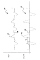
次に、図4を参照すると、ここには本明細書で開示されているホットワイヤ電源により生成可能な例示的な電圧波形401と電流波形411が示されている。図からわかるように、電圧波形401と電流波形411の各々は交流電流(AC)であり、この場合、波形の隣接するピークは反対の極性を有する。このようなホットワイヤ波形は、図1〜3の各々に示されているシステムで使用できる。しかしながら、レーザを使って溶融池を作るホットワイヤ工程においては(例えば、図1参照)、溶融池を撹拌することが望ましい場合があることが明らかとなっており、これは、レーザだけを使用したのでは実現できない。このような状況では、代替的電流波形411の使用により、溶融池が撹拌および振動される。この溶融池の動きは、ポロシティまたはその他の欠陥を低減させるのに役立ち、溶融池の結晶粒微細化に役立つ。それゆえ、本発明のいくつかの実施形態においては、図のようにAC加熱波形を使用することが望ましい。もちろん、留意すべき点として、他の波形も使用できるため、本発明の実施形態は図4に示される波形に限定されない。例えば、方形波バルス電流プロファイルも使用できる。
Referring now to FIG. 4, there is shown an
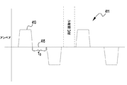
さらに、図のように、いくつかの例示的実施形態において、電流は電流パルス413間で0アンペアまで低下する。このような波形によってホットワイヤ140と被加工物との間の不用意なアーク放電イベントの発生を防止するための能動的な消弧が提供される。前述のように、ホットワイヤ140でのアーク放電イベントを防止することが望ましい。したがって、図のような例示的電流波形411において、波形411は隣接するパルス413間で、複数の0アンペア電流期間415が含まれる。すなわち、例示的実施形態において、電流パルス413は後続のパルス(異なる極性を有する)が生成される前に期間Toにわたり0アンペアまで低下する。この能動的な消弧は、不用意なアークイベントを防止するのに役立つ。本発明の例示的実施形態において、0アンペア期間Toはピークパルス電流、波形周期、およびパルス幅に基づいて事前に決定される期間である。ゼロ電流期間はまた、先行するパルスの中で生成されたアークがあれば、そのすべてを消す。例示的実施形態において、0アンペア期間は、電流パルス413の持続期間Tpの80〜120%の範囲内である。別の例示的実施形態において、0アンペア期間Toは電流パルス413の期間Tpより大きい。
Further, as shown, in some exemplary embodiments, the current drops to 0 amperes between
さらに、また別の例示的実施形態において、0アンペア期間Toは、ホットワイヤ工程中に熱入力を制御するために変化させることができる。すなわち、期間Toを短縮して入力を増大させることができ、期間Toを延長して熱入力を減少させることができる。それゆえ、いくつかの例示的実施形態において、ワイヤ140および/または溶融池の熱をモニタし(本願に援用される優先権出願参照)、検出された温度に基づいて、ホットワイヤ電源が0アンペア期間Toの持続期間を調整して所望の温度に到達させることができる。
Furthermore, in yet another exemplary embodiment, the 0 ampere period To can be varied to control the heat input during the hot wire process. In other words, the period To can be shortened to increase the input, and the period To can be extended to decrease the heat input. Therefore, in some exemplary embodiments, the heat of the
さらに、前述のように、アーク溶接工程がホットワイヤ工程と共に使用されるこれらの実施形態において、アーク溶接電源はGMAWまたはGTAW電源と工程の何れでも使用できる。しかしながら、いくつかの例示的実施形態において、GTAW工程が利用される場合、GTAW工程は、自動電圧制御(AVC)読取りが、ホットワイヤ波形411の中の0アンペア期間415の間にのみ行われるように制御される。一般に知られているように、GTAW(ティグ)溶接中、多くのGTAW電源が溶接工程中に、GTAW工程のアーク長を判断するためにアークを通る電圧を測定するAVC読取りを行い、最終的にGTAW工程のアーク長の制御に役立つ。GTAW型電源の構成、機能、および動作と、自動電圧制御の使用は、当業者にとってよく知られているため、何れも本明細書で詳しく説明する必要はない。例えば、ある例示的AVCユニットは、制御ユニットと、機械的スライドまたは移動機構と、を含み、それらにトーチが連結され、制御ユニットはアーク電圧の読取り値を取得して、機械的スライド/移動機構を上下に(およびしたがって、トーチを上下に)移動させて、所望の電圧を保持する。しかしながら、相互に近接していることから、ホットワイヤ電流パルスは、GTAWアークのアーク長に影響を与える可能性があることが明らかとなっている。これは概して図5に示されている。図のように、GTAW電極500は、電極500と溶接溶融池WPとの間にアークを発生させるために使用される。しかしながら、ホットワイヤ電流パルス中に、磁場MFが生成され、これはアークをプルまたはプッシュすることができる。(明瞭にするために、ホットワイヤ140は横に示されているが、電極500に関して半径方向の何れの位置に位置付けることもできる点に留意されたい。)アークを移動させることにより、アークの長さが変化するため、変化したアーク長期間中に取られた全てのAVC読取り値が影響を受け、電極と溶融池との間の距離を正確に反映せず、あるいは、それ以外に、不正確な電圧読取値となる。例えば、AVC読取り値は、GTAWアーク長が増大したことを示すことができ、それゆえ、GTAW電源に、電極500が溶融池から引き離されたかのように反応させる。しかしながら、ホットワイヤ電流パルスがオフにされるか、低減化されると、アーク長はその通常位置に戻り、そのため、GTAW電源によるアーク長の「増大」の補償が不適当となり、GTAW工程に不利な影響を与える。したがって、本発明の実施形態はホットワイヤ電源とGTAW電源を同期させ、それによって、GTAW電源を制御するために使用される自動電圧制御読取り値は、ホットワイヤ波形411の0アンペア期間Toでのみ取られる。具体的には、図6に示されるように、AVC読取り値は期間To(電流が0アンペアの時)にのみ取られる。いくつかの例示的実施形態において、AVC読取り値は、電流が0アンペアである時に取られるが、何れの隣接する電流パルス413の何れとも近すぎない。例えば、いくつかの例示的実施形態において、GTAW工程のAVC読取り値は、期間Toの中の中央の80%で取られる。すなわち、GTAW工程に関するAVC読取り値は、期間Toの最初と最後の10%の部分では取られず、この場合、第一の部分は期間Toの、パルス413に続くToであり、最後の部分は、期間のうち、後続のパルス413までの10%である。GTAWとホットワイヤ工程との間のこのような同期を利用することによって、GTAW工程はその完全性を保持できる。
Further, as described above, in those embodiments where the arc welding process is used in conjunction with a hot wire process, the arc welding power source can be used with either a GMAW or GTAW power source and process. However, in some exemplary embodiments, if a GTAW process is utilized, the GTAW process is such that an automatic voltage control (AVC) reading is performed only during the 0
典型的には、GTAW溶接電流は定電流であり、多くの用途において、AVC回路または制御ユニットは、標準的GTAW電源の一部ではない。それゆえ、本願のいくつかの例示的実施形態において、AVCユニットまたは回路(明瞭さのために図示せず)は自立ユニットであり、本明細書で説明するように、ホットワイヤの不感時間と同期される。AVC回路およびユニットの構成と動作は当業者により一般的に知られている。 Typically, the GTAW welding current is a constant current, and in many applications the AVC circuit or control unit is not part of a standard GTAW power source. Thus, in some exemplary embodiments of the present application, the AVC unit or circuit (not shown for clarity) is a self-supporting unit and is synchronized with hot wire dead time as described herein. Is done. The configuration and operation of AVC circuits and units are generally known by those skilled in the art.
GMAW工程をACホットワイヤプ工程と共に利用する本発明の例示的実施形態において、それぞれの波形を同期させ、波形を相互に概して同相に保つことも望ましい。これまでに明らかになったこととして、相対的波形のピークの位相がずれていると、ホットワイヤ電流により生成される磁場は、特にGMAW工程がそのバックグラウンド位相にあるとき、すなわち、バックグラウンドアーク中、GMAW工程のアークを大きくプルすることができる。これは、そのバックグラウンドレベルがより低いGMAW溶接波形を使用する場合に特に当てはまる。例えば、ステンレスおよびニッケル合金等の異なる合金を溶接するとき、GMAWパルスパラメータは比較的低いバックグラウンド電流を使用する。低いバックグラウンド電流はアーク力の低いアークを生成し、それによってこれらはホットワイヤパルスの影響を受けやすくなる。これは、ピーク電流レベルの高いホットワイヤパルスの場合に特に当てはまる。したがって、例示的実施形態において、それぞれの波形を同期させて、概してこれらを同相にすることにより、GMAWアークの安定性を確保することが望ましい可能性がある。いくつかの例示的波形が図7A〜7Cに示されている。 In an exemplary embodiment of the invention that utilizes a GMAW process in conjunction with an AC hot wire process, it is also desirable to synchronize the respective waveforms and keep the waveforms generally in phase with one another. As has been shown so far, when the peak of the relative waveform is out of phase, the magnetic field generated by the hot-wire current will be in particular when the GMAW process is in its background phase, ie the background arc. Inside, the arc of the GMAW process can be greatly pulled. This is especially true when using a GMAW weld waveform whose background level is lower. For example, when welding different alloys such as stainless steel and nickel alloys, the GMAW pulse parameter uses a relatively low background current. The low background current creates arcs with low arc power, which makes them susceptible to hot wire pulses. This is especially true for hot wire pulses with high peak current levels. Thus, in an exemplary embodiment, it may be desirable to ensure the stability of the GMAW arc by synchronizing the respective waveforms so that they are generally in phase. Some exemplary waveforms are shown in FIGS.
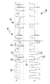
図7A〜7Cの各々は、本明細書に記載されているように、GMAW/ホットワイヤ工程のための例示的な同期電流波形を示している。留意すべき点として、それぞれのGMAW波形701の各々は正の波形で示されているが、これらはAC波形とすることもできる。これに加えて、図7Aおよび7Bにおけるホットワイヤ波形711の各々はACとして示されているが、これらは単一極性を有するようにすることもできる。さらに、図7Cにおけるホットワイヤ波形711は単一極性を有するように示されているが、これはAC波形とすることもできる。上述の代替案は、本発明の主旨または範囲から逸脱せずに使用できる。
Each of FIGS. 7A-7C shows an exemplary synchronous current waveform for a GMAW / hot wire process, as described herein. It should be noted that although each
ここで、図7Aを参照すると、GMAW波形701は複数の電流パルス703を有するように示されており、その各々はピーク電流レベル705を有する。さらに、パルスの各々はバックグラウンド電流部分707により分離される。バックグラウンド電流部分は、10〜250アンペアの範囲の公称電流レベルを有することができる。また、複数のパルス713を有するホットワイヤ電流波形711も示されている。波形711はACであり、パルス713の各々はピーク電流レベル715を有し、前述のように、0アンペア部分717により分離されている。ホットワイヤパルス713のピーク電流レベル715は、250〜500アンペアの範囲内とすることができる。これに加えて、波形は同期され、同相であり、それによって波形間の位相角Φは340〜20°の範囲内である。いくつかの例示的実施形態において、位相角Φは355〜5度の範囲内であり、他の実施形態において、位相角Φは0度である。波形を同期させ、本明細書に記載されている位相角を利用することによって、本発明の実施形態は、GMAWアークがホットワイヤ電流波形によって過剰に影響を受けないようにするのに役立つ。
Referring now to FIG. 7A, the
図7Bは、他の例示的波形を示しており、この場合、ホットワイヤ電流パルス713はGMAW波形701と同期され、それによってホットワイヤパルスピーク715は図のようにGMAWパルスピーク715に先行する。すなわち、ホットワイヤパルスは、GMAWパルスがそれらのそれぞれのピーク705の電流レベルに到達する前にそれらのピーク電流レベル715に到達する。例示的実施形態において、それぞれのピーク間の位相角Φは、340〜359度の範囲内である。それに加えて、ホットワイヤピーク電流レベル715は、GMAW工程中の溶滴の分離の前の時間tで終了する。明瞭にするために、溶滴の分離は図7Bにおいて、GMAWパルス703の終了時に描かれているが、溶滴分離は使用される波形に依存し、それゆえ、必ずしも図のようにパルス703の終了時でなくてもよいと理解される。当業者は一般に、GMAW工程の溶滴搬送メカニクスを理解しているため、これらを本明細書で詳しく説明する必要はない。前述のように、ホットワイヤパルス713のピークレベル715は、GMAW液滴分離の前の時間tで終了する。例示的実施形態において、時間tは50〜1000μsの範囲内である。他の例示的実施形態において、時間tは50〜200μsの範囲内である。このような実施形態において、溶滴飛翔はホットワイヤ電流により影響を受けない(または、ほとんど影響を受けない)。
FIG. 7B shows another exemplary waveform, in which the hot wire
図7Cは、本発明のまた別の例示的実施形態示している。この例示的実施形態において、GMAW波形701は同期され、それによってパルス703の各々はホットワイヤパルス713の前に始まる。例示的実施形態において、GMAWパルス703の開始はホットワイヤパルス713の開始の、1〜20度の位相角Φだけ先行する。他の例示的実施形態において、位相角Φは300〜50度の範囲内である。しかしながら、GMAWパルスはホットワイヤパルスに先行するが、GMAWパルスの電流ランプアップレート709は、ホットワイヤパルス713のランプアップレート719より小さい。例えば、パルススプレイ工程に関して、ランプレートは350〜500A/msの範囲内とすることができ、ホットワイヤの場合、ランプレートは350〜700A/msの範囲内とすることができる。ホットワイヤパルス713により低いランプレートを利用することによって、GMAWアークはホットワイヤピークのプルに対する抵抗力をより高くすることができる。他の例示的実施形において、ホットワイヤパルス713はGMAWパルスのそれより高いランプレートを利用し、ホットワイヤパルス713がそのピーク電流レベル715に、GMAWパルス703がそのそれぞれのピーク705のレベルに到達する前に到達するようになっている。留意すべき点として、いくつかの用途において、ホットワイヤピーク電流は低電流アークに大きく影響を与える可能性があり、これは例えば、アーク電流が低いバックグラウンド状態にある場合である。これは、干渉する磁場による。同様に、ホットワイヤ電流ピークはまた、溶滴の搬送にも影響を与える可能性がある。それゆえ、いくつかの例示的実施形態において、ホットワイヤ電流のピークをアーク溶接ピーク中、ただし溶滴の搬送前に有することが有利である。
FIG. 7C illustrates yet another exemplary embodiment of the present invention. In this exemplary embodiment, the
図8は、本発明の実施形態に使用される、ある例示的なAVCシステムを示している。システム800は、本明細書で説明され、記載されている実施形態に適合する方法で動作する。AVC制御ユニットは、GTAW電源、トーチ、および被加工物の各々に連結される。また、同期ライン805はAVC制御回路801をホットワイヤ電源に連結する。移動機構804は、本明細書に記載されているように、トーチを上下に移動させてアーク電圧を保持する。図8にはまた、GTAW電流807も示されており、これは定電流として示され、代表的なホットワイヤ電流出力809は、AVC検出811がホットワイヤ電流出力のオフ時間と同期していることを示している。
FIG. 8 illustrates an exemplary AVC system used in embodiments of the present invention.
前述のように、それぞれの波形の同期は、ホットワイヤ工程に加えてGMAWまたはGTAW工程の何れが使用されていても望ましい。電流波形を同期させるために使用可能な回路と制御方法は、溶接業界で一般に知られ、使用されている。これらの方法は、本明細書に記載されている実施形態に同様に使用できる。そのため、同期方式と制御方法の詳細な説明は本明細書では繰り返さない。さらに、本明細書に記載されている各種の例示的システムは、本明細書に記載されている動作を制御するために各種のコントローラ部品を使用できる。例えば、溶接およびホットワイヤ電源の各々は、それぞれ、各電源を制御し、同期させるための共通のコントローラに連結することができる。それに加えて、マスタ−スレーブ関係を使用でき、この場合、電源のうちの一方(例えばGTAWまたはGMAW電源)はマスタ電源の役割を果たし、ホットワイヤ電源の機能はマスタ電源に隷属する。もちろん、同期のための他の方法も、本発明の主旨または範囲から逸脱せずに使用可能である。 As described above, the synchronization of each waveform is desirable regardless of whether the GMAW or GTAW process is used in addition to the hot wire process. Circuits and control methods that can be used to synchronize current waveforms are generally known and used in the welding industry. These methods can be used as well for the embodiments described herein. Therefore, detailed description of the synchronization method and the control method will not be repeated in this specification. Further, the various exemplary systems described herein can use various controller components to control the operations described herein. For example, each of the welding and hot wire power supplies can be coupled to a common controller for controlling and synchronizing each power supply, respectively. In addition, a master-slave relationship can be used, where one of the power supplies (eg, GTAW or GMAW power supply) serves as the master power supply and the function of the hot wire power supply is slaved to the master power supply. Of course, other methods for synchronization may be used without departing from the spirit or scope of the present invention.
前述のように、各種のタンデムコンビネーションを本明細書に記載されているホットワイヤ溶着工程と共に使用できる。例えば、GMAW型工程を使用でき(図2参照)、またはGTAW工程を使用できる(図5参照)。さらに、本明細書に記載されているように、ホットワイヤ電流波形はACとすることができ、それゆえ、正と負の極性部分またはパルスの両方を有する。さらに、一般に理解される点として、ホットワイヤ消耗材によるアークの生成(すなわち、ホットワイヤと溶融池との間)は、工程にとって有害となりえ、それゆえ、ほとんどの場合、このようなアーク放電は望ましくない。各種の技術、システム、および工程は、ホットワイヤ(例えば、図5の140参照)と溶融池との間のアーク生成を抑制するための各種の技術、システム、および工程が開発されてきた。これらの工程/システム/方法は、本願の譲受人による他の係属中の特許出願において十分に説明されており、これらの工程は本明細書では詳しく説明しない。 As mentioned above, various tandem combinations can be used with the hot wire welding process described herein. For example, a GMAW type process can be used (see FIG. 2) or a GTAW process can be used (see FIG. 5). Further, as described herein, the hot wire current waveform can be AC, and thus has both positive and negative polar parts or pulses. Furthermore, it is generally understood that the generation of an arc by hot wire consumables (ie, between the hot wire and the weld pool) can be detrimental to the process, and in most cases such arcing is Not desirable. Various techniques, systems, and processes have been developed to suppress arc generation between the hot wire (eg, 140 in FIG. 5) and the molten pool. These processes / systems / methods are fully described in other pending patent applications by the assignee of the present application, and these processes are not described in detail herein.
しかしながら、近年になって明らかとなったこととして、特定の工程/用途においては、いつくかの既知のホットワイヤ用消弧技術がホットワイヤ項工程に有害でありえ、それによって工程が弊害を受ける可能性があり、および/またはそれを止めて、再開させる必要があるかもしれず、これは望ましくない。これについては、本明細書に記載されている消弧の問題を排除するために使用される、本発明の例示的実施形態と共に後で説明する。さらに留意される点として、以下の説明は特に、GTAWタンデムプロセスの中で可変極性ホットワイヤ波形を使用する本発明の実施形態に関する。しかしながら、例示的実施形態はタンデムでのGTAWの使用に限定されず(例えば、図5参照)、本明細書に記載されている実施形態はGMAW、レーザ、その他にも使用できる。 However, it has become clear in recent years that, in certain processes / applications, some known hot wire arc extinguishing techniques can be detrimental to the hot wire term process, which can adversely affect the process. And / or may need to be stopped and restarted, which is undesirable. This will be described later along with an exemplary embodiment of the present invention that is used to eliminate the arc-extinguishing problem described herein. It is further noted that the following description relates specifically to embodiments of the present invention that use variable polarity hot wire waveforms in a GTAW tandem process. However, the exemplary embodiments are not limited to the use of GTAW in tandem (see, eg, FIG. 5), and the embodiments described herein can be used for GMAW, lasers, and others.
前述のように、これまでに明らかとなった点として、特定の用途では、ホットワイン電流のための既知の消弧技術には動作上の限界がありうる。例えば、ACホットワイヤをGTAW工程と共に使用した場合、この種の工程は高速で動作させられ、および/または溶着に関して溶着速度の問題が発生する。すなわち、場合によっては、ホットワイヤ消耗材(例えば、図5の140)が適正に溶着されないことが観察された。例えば、溶接ヘッドが熱を失い、それゆえ、「冷たく」なりえ、その結果、消耗材が溶着部で「粘着性を持つ」。さらに、ホットワイヤ/溶融池分離によるアークの生成等の故障モードが発生すると、既知の消弧技術では故障を適正に回避できず、これはスパッタの生成の原因となり、溶融池を飛び跳ねさせ、および/またはGTAW工程のタングステン電極と干渉する可能性があることも観察されている。 As previously mentioned, it has become clear that in certain applications, known arc extinguishing techniques for hot wine currents may have operational limitations. For example, when an AC hot wire is used with a GTAW process, this type of process is operated at high speed and / or a welding speed problem occurs with respect to welding. That is, in some cases, it was observed that hot wire consumables (eg, 140 in FIG. 5) were not properly welded. For example, the welding head loses heat and can therefore be “cold”, so that the consumable is “sticky” at the weld. Furthermore, when failure modes such as arc generation due to hot wire / molten pool separation occur, the known arc extinguishing technique cannot properly avoid the failure, which causes spatter formation, causing the molten pool to jump and It has also been observed that it may interfere with the tungsten electrode of the GTAW process.
上述の問題の例示的な電圧および電流波形が図9に示されている。具体的には、図9は、GTAWアーク工程と組み合わせて使用された時に、可変極性ホットワイヤ溶着信号の例示的な電圧波形910と電流波形920を示している。一般に理解されているように、通常動作中、ワイヤ140は溶融池と接触し、基本的に、溶融池WPと同じ電位である。例示的実施形態において、ホットワイヤ140の電圧は、ホットワイヤ工程のコンタクトチップ160から被加工物まで、約2ボルトである。多くの場合に、ワイヤの端は溶融池と接触しなくなると、電圧が大きく上昇し、これは、ワイヤが溶融池から離れ、アークが発生する可能性があることを示す。これは、ほとんどの場合において望ましくない。この電圧上昇が検出されると、システムは消弧ルーチンを実行して、アークを除去/防止し、ワイヤ140を再び溶融池と接触させることができる。しかしながら、いくつかの用途/例において、ワイヤ140の端が溶融池と接触していなくても、ワイヤ140の端はタンデムアーク溶接工程のプラズマプルーム、例えばGTAWパラズマプルームの中に入る可能性がある。このことが発生すると、プラズマプルームはホットワイヤ電流が溶融池/被加工物まで移動する経路を提供する。そのため、特定の状況では、既知の消弧技術ではワイヤ140と溶融池との間の不接触に適切に、または素早く対処できない。これは図9において概して示されている。
An exemplary voltage and current waveform for the above problem is shown in FIG. Specifically, FIG. 9 shows an
図9に示されるように、典型的なACホットワイヤ波形は交互の極性の電流および電圧バルス、すなわちパルスAで動作する。点Bにおいて、負の極性の電圧スパイク911が検出され、これはワイヤ140が溶融池と接触しなくなったことを示す。この検出後、電流は(いくつかの既知の消弧技術に従って)オフにされる−C参照。電流がオフにされた後、オンに戻され、通常の電流パルスが再開される−D。多くの場合に、これは通常の動作をトリガするはずである。しかしながら、上述のような場合において、また別の電圧スパイクEが消弧の試行の後に発生し、消弧の試行が続くと状況が悪化し、徐々にさらに悪くなりF、最終的に工程を停止し、再開しなければならない。
As shown in FIG. 9, a typical AC hot wire waveform operates with alternating polarity current and voltage pulses, ie pulse A. At point B, a negative
理解される点として、GTAW工程のタングステン電極(例えば、図5の500)とホットワイヤ140はどちらも極性が両方とも負であるとき(ACホットワイヤ電流波形の負の半サイクル)、電流は溶融池からワイヤ140へと流れるが、タングステン500を通らない。それに加えて、ホットワイヤ電流からの磁力があり、それがGTAWアークをワイヤ140に向かってプルする。このプルによって、ホットワイヤ140がさらに加熱され、それによって負の半サイクル中にアークが発生しやすくなると考えられている。前述のように、ワイヤ140がアーク放電すると/するとき、消弧が溶融池からワイヤ140への電流を電圧スパイク(陽極/陰極電圧の生成)として検出し、ホットワイヤの出力を停止する。ワイヤが溶融池と接触していないときに他の負の半サイクルが試行されると、ワイヤ140と溶融池との間に電圧が生じ、消弧がその電圧を検出できる。
It is understood that when both the GTAW process tungsten electrode (eg, 500 in FIG. 5) and
しかしながら、ホットワイヤ140が波形920の中の正の部分にあるとき、電位電流がワイヤ140からアークを通じてタングステン500へと流れる経路となる。通常、ワイヤ140が溶融池と接触しているとき、ホットワイヤ電流の磁気によるプッシュがアークプラズマをホットワイヤ140から遠ざけるようにプッシュし、短絡接続によって電圧が、電流がホットワイヤから溶融池を通じてタングステン500へと流れるのに十分に低く保たれる。問題は、ワイヤ140と溶融池との間の接続が失われると始まると考えられている。この状況では、電流はワイヤ140から(正のとき)、プラズマを通ってタングステン500に直接流れることができる。これが発生すると、少なくとも2つの問題が生じる:すなわち、(1)ワイヤ140が接続しなくなっても、ホットワイヤ電源が溶融池とワイヤ140との間のアーク(陽極/陰極電圧)を検出しないことと、(2)電流(ワイヤ140からタングステン電極500に伝送される)が溶融池を通らなくなり、溶融池から熱が奪われることである。その結果、ワイヤ140が燃えてタングステン500から離れ(アークの加熱よる)、溶融池は冷たく、粘着性を有することになる。多くの場合、波形の正の側だけが安定し、したがって、工程を停止し、再開する必要が生じる。
However, when the
本発明の実施形態は、特にGTAW工程が負の極性の工程である場合に上述の問題に対処する。すなわち、GTAW電流は負である。上述の問題に対処するために、本発明の例示的実施形態は、負の極性にある時に、ワイヤ140が溶融池と接続されたことを検出する。ワイヤ140が溶融池に接続されると、波形の負の半サイクルが動作でき、負の半サイクルが電圧スパイクを発生させずに動作すると、ワイヤ140は依然として溶融池と接続されている/接触していると判断され、すると、正の半サイクルが動作できる。これを説明する例示的な電圧および電流波形が図10に示されている。
Embodiments of the present invention address the above problems, particularly when the GTAW process is a negative polarity process. That is, the GTAW current is negative. To address the above problems, the exemplary embodiment of the present invention detects that the
図10は、本発明のある例示的実施形態の電圧波形1010と電流波形1020を示している。この実施形態において示されているように、アークおよび/またはワイヤ/溶融池分離は、正のパルスの後の点Aにおいて検出され、負の電圧スパイクにより示される。この検出に基づいて、電源(例えば、図1の170参照)により、ACパルス波形の負の半サイクルは動作または開始せず、ACパルス波形の次の正の半サイクルは動作しない−B。スキップされた正の半サイクルの後、電源170は次の負の半サイクルの動作を試行するが、他の電圧スパイクがCで検出される。この追加の電圧スパイクは、ワイヤ140が溶融池とまだ接触していないことを示し、それゆえ、電源は負の半サイクルと次の正の半サイクルを再びスキップさせる−D。このスキップの後、電源170は電流1020の負の半サイクルを再び開始し−点E−今度は電圧スパイクが検出され(ワイヤ140が再び溶融池と接触した状態に戻ったことを示す)、したがって、負のパルスと次の正の半サイクルパルスFが開始され、動作する。これは、電圧スパイク(例えば、「G」を)が検出されると、必要に応じて繰り返される。すなわち、電圧スパイクが検出されると、アークおよび/またはワイヤの溶融池からの分離を示す。これが検出されると、電源はACパルス波形1020を停止させ、本明細書に記載されているような遮断ルーチンを実行する。具体的には、閾値電圧が検出されると(スパイクを示す)、電源170は交互の極性の後続の2つのパルスをスキップし、アーク溶接工程(例えば、GTAW工程)の極性と同じ極性を持つ次のパルスを開始する。例えば、GTAW電流が負の電流である場合、本明細書に記載されている遮断ルーチンの例示的実施形態は、アークまたは分離が検出されると、すぐ次の負の電流パルスとすぐ次の正の電流パルスをスキップし、GTAW電流と同じ極性(負)の次の電流パルスを開始する。言い換えれば、少なくとも1つ波形のフルサイクル(正と負のパルス)がスキップされ、電源は、アーク溶接工程(GTAWまたはGMAW等)と同じ極性を持つ次の後続パルス(このスキップされたサイクルの後)を開始する。すると、電源170は、アーク溶接の極性と同じ極性のパルスがうまく動作した時だけ、反対の極性の後続パルスを開始する。それゆえ、1つのフルサイクルがスキップされ、同じ極性の次のパルスが開始された後に、電圧スパイクが検出されると、パルスの別のフルサイクルがスキップされ、同じ極性の次のパルスが再び試行される。アーク溶接電流と同じ極性のパルスがうまく完了した後にのみ、電源170は反対の極性の後続の半サイクルのパルスを開始する。本発明の例示的実施形態は、上述の問題を回避し、交互の極性のホットワイヤ溶着工程の実行を最適化するのに役立つ。このようなシステムでは、アーク放電が電源から遠ざからず、スムーズな最適化された動作が得られる。
FIG. 10 illustrates a
例示的実施形態において、上述の閾値は電圧レベルでも、dv/dtレベルでもよい。すなわち、いくつかの例示的実施形態において、電源170は電圧の変化率を検出することができ、変化率が閾値の変化率を超えると、アーク放電および/または接触イベントの喪失が発生しているか、発生しようとしていると判断され、上述の遮断機能が実行される。閾値が電圧レベルである実施形態において、電圧レベルは電源170における所定のレベルでも、電源170への入力に基づいて、または使用される波形に基づいて判断されるレベルでもよい。いくつかの例示的実施形態において、電圧閾値は少なくとも+/−5ボルトとすることができる。すなわち、0ボルトとは5ボルトまたはそれ以上異なる(正または負の何れでもよい)電圧スパイクがある場合、電源は本明細書に記載されているような遮断ルーチンを開始する。他の例示的実施形態において、電圧閾値は少なくとも+/−3.5ボルトである。また別の例示的実施形態において、電圧閾値は少なくとも+/−7ボルトである。
In an exemplary embodiment, the above threshold may be a voltage level or a dv / dt level. That is, in some exemplary embodiments,
他の例示的実施形態において、アーク/分離の検出後、ACホットワイヤ電流の2つのフルサイクルをスキップすることができ、その後、アーク溶接電流と同じ極性の半パルスが開始される。いくつかの例示的実施形態において、スキップされるフルサイクルの数は、ホットワイヤ140のワイヤ送給速度に基づいて決定される。すなわち、ワイヤ送給速度が第一の速度(例えば、ある閾値を超えるWFS速度)である場合、電源170は1つのフルサイクルだけをスキップしてから、後続の同じ極性のパルスを試行するが、ワイヤ送給速度が第二の速度(例えば、ある閾値より低い)であると、電源は2つ(またはいくつかの実施形態ではそれ以上)のフルサイクルをスキップしてから、後続の同じ極性のパルスを施行する。このWFS閾値レベルは事前決定されても、ホットワイヤ溶接工程への使用者からの入力情報に基づいていてもよい。
In other exemplary embodiments, two arcs of AC hot wire current can be skipped after arc / separation detection, after which a half pulse of the same polarity as the arc welding current is initiated. In some exemplary embodiments, the number of full cycles to be skipped is determined based on the wire feed rate of
上記の説明は、溶接作業中の制御と動作に焦点を当てたものであるが、同様の方法はこのような溶接作業を開始し、または始める時に採用されるべきである。すなわち、本明細書に記載されている例示的システムを開始する際、アーク溶接作業はまず、アークと、ホットワイヤが接触する溶融池を作るために開始される。ホットワイヤ電流は、アーク溶接電流の後に開始され、例示的実施形態において、ホットワイヤ電流の開始パルスはホットワイヤ電流の開始時のアーク溶接電流と同じ極性を有する。すなわち、アーク溶接波形がホットワイヤ開始時に負の極性を有する場合、ホットワイヤ電流は負の極性で開始するべきである。これによって電流が確実に正しい流路をたどることになる。いくつか実施形態において、それぞれの電流が反対の極性を有する場合、ホットワイヤ電流は、アークプルームを介して溶融池と接触して流れることができる。例示的実施形態において、ホットワイヤ溶接電流は、溶融池との接触が検出された後に、同じ極性で開始される。この検出は、前述のものと同様とすることができ、例えば電圧等を使用する。いったん検出されると、ホットワイヤ工程が開始され、分離が検出されるまで継続され、すると、システムは本明細書に記載されているように応答する。 Although the above description has focused on control and operation during the welding operation, similar methods should be employed when starting or starting such a welding operation. That is, in starting the exemplary system described herein, an arc welding operation is first initiated to create a molten pool where the arc and hot wire are in contact. The hot wire current is initiated after the arc welding current, and in an exemplary embodiment, the hot wire current start pulse has the same polarity as the arc welding current at the start of the hot wire current. That is, if the arc welding waveform has a negative polarity at the start of the hot wire, the hot wire current should start with a negative polarity. This ensures that the current follows the correct flow path. In some embodiments, hot wire current can flow in contact with the molten pool via the arc plume if each current has the opposite polarity. In the exemplary embodiment, the hot wire welding current is initiated with the same polarity after contact with the weld pool is detected. This detection can be similar to that described above, for example using voltage or the like. Once detected, the hot wire process is initiated and continued until separation is detected, and then the system responds as described herein.
前述のように、上述のようなそれぞれの波形の開始、出力、および制御とそれぞれの遮断機能は、ホットワイヤ工程に加えてGMAWまたはGTAW工程の何れが使用されても望ましい。本明細書に記載されているように、波形および遮断ルーチンを制御するために使用可能な回路と制御方法は溶接業界で一般に知られ、使用されている。これらの方法は、本明細書に記載されている実施形態にも同様に利用できる。そのため、制御技術と制御方法の詳細な説明は、本明細書では繰り返さない。さらに、本明細書に記載されている各種の例示的システムは、本明細書に記載されている動作を制御するための各種のコントローラ構成要素を使用できる。例えば、溶接およびホットワイヤ電源の各々は、それぞれの各電源を制御し、同期させる共通のコントローラに連結することができる。それに加えて、マスタ−スレーブ関係を利用でき、その場合、電源の一方(例えば、GTAWまたはGMAW電源)はマスタ電源の役割を果たし、ホットワイヤ電源の機能はマスタ電源に隷属する。もちろん、同期/制御のための他の方法も、本発明の主旨または範囲から逸脱せずに使用できる。 As described above, the start, output, and control of each waveform as described above and the respective shut-off functions are desirable regardless of whether the GMAW or GTAW process is used in addition to the hot wire process. As described herein, circuits and control methods that can be used to control the waveform and shut-off routines are generally known and used in the welding industry. These methods are equally applicable to the embodiments described herein. Therefore, detailed description of the control technique and control method will not be repeated in this specification. Further, the various exemplary systems described herein can use various controller components to control the operations described herein. For example, each of the welding and hot wire power supplies can be coupled to a common controller that controls and synchronizes each respective power supply. In addition, a master-slave relationship can be utilized, in which case one of the power supplies (eg, GTAW or GMAW power supply) serves as the master power supply, and the function of the hot wire power supply is slaved to the master power supply. Of course, other methods for synchronization / control may be used without departing from the spirit or scope of the present invention.
本発明を特定の実施形態に関連して説明したが、当業者であれば、本発明の範囲から逸脱せずに、各種の変更を加え、均等物と置き換えてもよいことがわかるであろう。それに加えて、特定の状況または材料を本発明の教示に適応させるために、その範囲から逸脱せずに多くの変更を加えることができる。したがって、本発明は説明されている特定の実施形態に限定されず、本発明は本願の範囲内に含まれるすべての実施形態を包含することが意図される。 Although the present invention has been described with reference to particular embodiments, those skilled in the art will recognize that various modifications may be made and replaced with equivalents without departing from the scope of the invention. . In addition, many modifications may be made to adapt a particular situation or material to the teachings of the invention without departing from the scope thereof. Accordingly, the invention is not limited to the specific embodiments described, and the invention is intended to encompass all embodiments included within the scope of the application.
100 システム
115 被加工物
130 レーザ電源
140 ホットワイヤ
170 ホットワイヤ電源
195 検出および電流制御サブシステム
200 システム
211 消耗材
213 電源
300 システム
301 アーク溶接電源
310 ホットワイヤ電源
313 事前設定加熱電圧回路
401 電圧波形
411 電流波形
413 電流パルス
415 0アンペア電流期間
701 GMAW波形
703 GMAWパルス
705 ピーク電流レベル
711 ホットワイヤ波形
713 ホットワイヤパルス
715 ピーク電流レベル
717 0アンペア部分
800 システム
809 ホットワイヤ電流出力
1010 電圧波形
1020 電流
100
Claims (18)
溶接電流を溶接作業に供給して、溶接アークおよび溶融池を生成するステップと、
ホットワイヤ溶接消耗材を前記溶融池に供給するステップと、
前記溶接作業中にホットワイヤ溶接波形を前記溶接消耗材に供給するステップであって、前記ホットワイヤ溶接波形は、複数の完全なパルスを有するAC波形であり、前記完全なパルスの各々は、第一の極性を有する第一のパルス部分および第二の極性を有する第二のパルス部分を含むステップと、
前記ホットワイヤ溶接消耗材と前記溶融池との間の分離を検出するステップと、
前記検出の後に前記ホットワイヤ溶接波形をオフにするステップと、
次の連続する第一または第二のパルス部分で前記ホットワイヤ溶接波形をオンにするステップであって、前記次の連続する第一または第二のパルス部分は前記溶接電流と同じ極性を有するステップと、
前記検出された分離が依然として存在するか否かを判断するステップと、
前記分離が依然として存在している場合、前記ホットワイヤ溶接波形をオフにして、前記第一または第二のパルス部分の、次の連続する他方をスキップし、前記分離が存在しなければ、前記第一または第二の次の連続するパルスを完了させるステップと、
を含む方法。 In the welding method,
Supplying a welding current to the welding operation to generate a welding arc and a weld pool;
Supplying hot wire welding consumables to the molten pool;
Supplying a hot wire welding waveform to the welding consumable during the welding operation, wherein the hot wire welding waveform is an AC waveform having a plurality of complete pulses, Including a first pulse portion having one polarity and a second pulse portion having a second polarity;
Detecting a separation between the hot wire welding consumable and the molten pool;
Turning off the hot wire welding waveform after the detection;
Turning on the hot wire welding waveform at the next successive first or second pulse portion, wherein the next successive first or second pulse portion has the same polarity as the welding current; When,
Determining whether the detected separation is still present;
If the separation is still present, turn off the hot wire welding waveform and skip the next successive other of the first or second pulse portion, and if the separation is not present, Completing one or second next successive pulses;
Including methods.
DC溶接電流を溶接作業に供給して、溶接アークおよび溶融池を生成するステップと、
ホットワイヤ溶接消耗材を前記溶融池に供給するステップと、
前記溶接作業中にホットワイヤ溶接波形を前記溶接消耗材に供給するステップであって、前記ホットワイヤ溶接波形は、複数の完全なパルスを有するAC波形であり、前記完全なパルスの各々は、負のパルス部分および正のパルス部分を含むステップと、
前記ホットワイヤ溶接消耗材と前記溶融池との間の分離を検出するステップと、
前記検出の後に前記ホットワイヤ溶接波形をオフにするステップと、
前記ホットワイヤ溶接波形をオフにした後に次の連続する負のパルス部分を開始するステップであって、前記次の連続する負のパルス部分の前記開始は次の後続の完全なパルスの開始時に始まるステップと、
前記検出された分離が依然として存在するか否かを判断するステップと、
前記分離が依然として存在している場合、前記ホットワイヤ溶接波形をオフにして、次の連続する正のパルス部分をスキップし、前記分離が存在しなければ、前記次の連続する負のパルス部分および前記次の連続する正のパルス部分を完了させるステップと、
を含む方法。 In the welding method,
Supplying a DC welding current to the welding operation to generate a welding arc and a weld pool;
Supplying hot wire welding consumables to the molten pool;
Supplying a hot wire welding waveform to the welding consumable during the welding operation, wherein the hot wire welding waveform is an AC waveform having a plurality of complete pulses, each of the complete pulses being negative. Including a pulse portion and a positive pulse portion of
Detecting a separation between the hot wire welding consumable and the molten pool;
Turning off the hot wire welding waveform after the detection;
Starting the next consecutive negative pulse portion after turning off the hot wire welding waveform, wherein the start of the next consecutive negative pulse portion begins at the start of the next subsequent full pulse. Steps,
Determining whether the detected separation is still present;
If the separation is still present, turn off the hot wire weld waveform and skip the next consecutive positive pulse portion; if the separation is not present, the next consecutive negative pulse portion and Completing the next consecutive positive pulse portion;
Including methods.
ホットワイヤ溶接消耗材を前記溶融池に供給し、前記溶接作業中にホットワイヤ溶接波形を前記溶接消耗材に供給するホットワイヤ溶接システムであって、前記ホットワイヤ溶接波形は、複数の完全なパルスを有するAC波形であり、前記完全なパルスの各々は、負のパルス部分および正のパルス部分を含むホットワイヤ溶接システムと、
を含む溶接システムにおいて、
前記溶接システムは、電圧閾値レベルを使って前記ホットワイヤ溶接消耗材と前記溶融池との間の分離を検出し、前記分離が検出されると、前記溶接システムは前記ホットワイヤ溶接波形をオフにし、
前記ホットワイヤ溶接波形をオフにした後に、前記システムは次の連続するパルス部分を開始しかつ判断し、前記次の連続するパルス部分中に、前記分離が依然として存在している場合、前記次の連続するパルス部分は前記溶接電流と同じ極性を有し、
前記溶接システムが前記分離は依然として存在すると判断すると、前記溶接システムは前記ホットワイヤ溶接波形をオフにして、他の次の連続するパルス部分をスキップし、前記分離が存在しないと、前記溶接システムは、前記次の連続するパルス部分および前記他の次の連続するパルス部分を完了させる
溶接システム。 An arc welding system for supplying a welding current to a welding operation to generate a welding arc and a weld pool;
A hot wire welding system for supplying hot wire welding consumables to the weld pool and supplying hot wire welding waveforms to the welding consumables during the welding operation, the hot wire welding waveforms comprising a plurality of complete pulses. A hot wire welding system, wherein each complete pulse includes a negative pulse portion and a positive pulse portion;
In a welding system including
The welding system detects a separation between the hot wire welding consumable and the weld pool using a voltage threshold level, and when the separation is detected, the welding system turns off the hot wire welding waveform. ,
After turning off the hot wire welding waveform, the system initiates and determines the next successive pulse portion, and if the separation is still present during the next successive pulse portion, The continuous pulse portion has the same polarity as the welding current,
If the welding system determines that the separation is still present, the welding system turns off the hot wire welding waveform and skips another next successive pulse portion, and if the separation is not present, the welding system A welding system for completing the next successive pulse portion and the other next successive pulse portion.
Applications Claiming Priority (4)
| Application Number | Priority Date | Filing Date | Title |
|---|---|---|---|
| US201662337821P | 2016-05-17 | 2016-05-17 | |
| US62/337,821 | 2016-05-17 | ||
| US15/287,448 | 2016-10-06 | ||
| US15/287,448 US20170334011A1 (en) | 2016-05-17 | 2016-10-06 | Method and system to use combination filler wire feed and high intensity energy source for welding and arc suppression of a variable polarity hot-wire |
Publications (2)
| Publication Number | Publication Date |
|---|---|
| JP2017205805A true JP2017205805A (en) | 2017-11-24 |
| JP2017205805A5 JP2017205805A5 (en) | 2020-06-18 |
Family
ID=58714866
Family Applications (1)
| Application Number | Title | Priority Date | Filing Date |
|---|---|---|---|
| JP2017091075A Ceased JP2017205805A (en) | 2016-05-17 | 2017-05-01 | Method and system to use combination of filler wire feed and high intensity energy source for welding and arc suppression of variable polarity hot-wire |
Country Status (4)
| Country | Link |
|---|---|
| US (1) | US20170334011A1 (en) |
| EP (1) | EP3246122A1 (en) |
| JP (1) | JP2017205805A (en) |
| CN (1) | CN107378238A (en) |
Families Citing this family (12)
| Publication number | Priority date | Publication date | Assignee | Title |
|---|---|---|---|---|
| CN107745174B (en) * | 2017-11-30 | 2023-08-18 | 华南理工大学 | Digital variable-polarity welding power supply based on SiC IGBT |
| US11383318B2 (en) * | 2018-02-02 | 2022-07-12 | Liburdi Engineering Limited | Filler wire position control |
| US11931835B2 (en) * | 2018-10-24 | 2024-03-19 | Lincoln Global, Inc. | Welding system for mitigating gun damage in pulsed arc welding |
| US12103121B2 (en) * | 2019-04-30 | 2024-10-01 | Illinois Tool Works Inc. | Methods and apparatus to control welding power and preheating power |
| CN111843112B (en) * | 2019-04-30 | 2025-06-06 | 伊利诺斯工具制品有限公司 | Method and device for controlling welding power and preheating power |
| US20210060680A1 (en) * | 2019-08-28 | 2021-03-04 | Lincoln Global, Inc. | Systems and methods providing coordinated dual power outputs supporting a same welding or auxiliary power process |
| CN110957904A (en) * | 2019-11-25 | 2020-04-03 | 中冶京诚工程技术有限公司 | Arc Power Supply System and Arc Power Supply Based on Rectangular Wave Signal |
| US12168271B2 (en) | 2020-11-06 | 2024-12-17 | Illinois Tool Works Inc. | Reciprocating preheating system, method, and apparatus |
| US12122001B2 (en) * | 2020-11-06 | 2024-10-22 | Illinois Tool Works Inc. | Asynchronous preheating system, method, and apparatus |
| CN112792432A (en) * | 2020-12-31 | 2021-05-14 | 福尼斯(南京)表面工程技术有限公司 | Polarity-variable double-tungsten-electrode surfacing system and using method thereof |
| CN114247966B (en) * | 2021-12-16 | 2023-04-25 | 北京工业大学 | Double-wire dissimilar material welding and material adding method based on variable polarity power supply |
| CN114247962B (en) * | 2021-12-16 | 2023-02-28 | 北京工业大学 | Multi-electrode time-sharing conduction and polarity-changing alternating arc welding and material adding method |
Citations (5)
| Publication number | Priority date | Publication date | Assignee | Title |
|---|---|---|---|---|
| JPS62192265A (en) * | 1986-02-17 | 1987-08-22 | Babcock Hitachi Kk | Hot wire tig welding equipment |
| EP0247628A2 (en) * | 1986-05-30 | 1987-12-02 | Babcock-Hitachi Kabushiki Kaisha | Method of control and apparatus for hot-wire welding |
| JPS6313672A (en) * | 1986-07-04 | 1988-01-20 | Babcock Hitachi Kk | Hot wire welding equipment |
| US20130043219A1 (en) * | 2009-01-13 | 2013-02-21 | Lincoln Global, Inc. | Method and system to start and use combination filler wire feed and high intensity energy source for welding |
| JP3198490U (en) * | 2012-07-12 | 2015-07-09 | リンカーン グローバル,インコーポレイテッド | Method and system for initiating and using a combination of welding wire feed and high energy source for welding |
Family Cites Families (10)
| Publication number | Priority date | Publication date | Assignee | Title |
|---|---|---|---|---|
| US3627974A (en) * | 1969-05-09 | 1971-12-14 | Air Reduction | Avoidance of current interference in consumable contact hot wire arc welding |
| JPS56131071A (en) * | 1980-03-18 | 1981-10-14 | Ishikawajima Harima Heavy Ind Co Ltd | All position tig welding method |
| JPH0679781B2 (en) * | 1984-07-02 | 1994-10-12 | バブコツク日立株式会社 | Hot wire TIG welding equipment |
| CA1266892A (en) * | 1985-04-27 | 1990-03-20 | Tadayuki Otani | Method of igniting arcs |
| KR0136197B1 (en) * | 1994-12-29 | 1998-07-01 | 김만제 | Arc length controller |
| JP4154153B2 (en) * | 2002-01-24 | 2008-09-24 | バブコック日立株式会社 | How to capture arc images |
| US8952291B2 (en) | 2005-09-15 | 2015-02-10 | Lincoln Global, Inc. | System and method for controlling a hybrid welding process |
| US20150158105A1 (en) * | 2009-01-13 | 2015-06-11 | Lincoln Global, Inc. | Method and system to use combination filler wire feed and high intensity energy source for welding with controlled arcing frequency |
| EP2777858B1 (en) * | 2013-03-15 | 2017-10-11 | Ewm Ag | Heating of a welding filler for arc welding |
| WO2015124996A2 (en) * | 2014-02-21 | 2015-08-27 | Lincoln Global, Inc. | Method and system to use combination filler wire feed and high intensity energy source for welding |
-
2016
- 2016-10-06 US US15/287,448 patent/US20170334011A1/en not_active Abandoned
-
2017
- 2017-05-01 JP JP2017091075A patent/JP2017205805A/en not_active Ceased
- 2017-05-10 CN CN201710324766.9A patent/CN107378238A/en active Pending
- 2017-05-16 EP EP17000834.6A patent/EP3246122A1/en not_active Withdrawn
Patent Citations (5)
| Publication number | Priority date | Publication date | Assignee | Title |
|---|---|---|---|---|
| JPS62192265A (en) * | 1986-02-17 | 1987-08-22 | Babcock Hitachi Kk | Hot wire tig welding equipment |
| EP0247628A2 (en) * | 1986-05-30 | 1987-12-02 | Babcock-Hitachi Kabushiki Kaisha | Method of control and apparatus for hot-wire welding |
| JPS6313672A (en) * | 1986-07-04 | 1988-01-20 | Babcock Hitachi Kk | Hot wire welding equipment |
| US20130043219A1 (en) * | 2009-01-13 | 2013-02-21 | Lincoln Global, Inc. | Method and system to start and use combination filler wire feed and high intensity energy source for welding |
| JP3198490U (en) * | 2012-07-12 | 2015-07-09 | リンカーン グローバル,インコーポレイテッド | Method and system for initiating and using a combination of welding wire feed and high energy source for welding |
Also Published As
| Publication number | Publication date |
|---|---|
| US20170334011A1 (en) | 2017-11-23 |
| CN107378238A (en) | 2017-11-24 |
| EP3246122A1 (en) | 2017-11-22 |
Similar Documents
| Publication | Publication Date | Title |
|---|---|---|
| JP2017205805A (en) | Method and system to use combination of filler wire feed and high intensity energy source for welding and arc suppression of variable polarity hot-wire | |
| US20150151375A1 (en) | Method and system to use combination filler wire feed and high intensity energy source for welding with controlled arcing frequency | |
| US20150158108A1 (en) | Method and system to use combination filler wire feed and high intensity energy source for welding with controlled arcing frequency | |
| US20150158107A1 (en) | Method and system to use combination filler wire feed and high intensity energy source for welding | |
| JP6559702B2 (en) | Method and system using AC welding corrugations and an enhanced consumable material that improves welding of galvanized workpieces | |
| US10239145B2 (en) | Synchronized magnetic arc steering and welding | |
| JP3198223U (en) | Method and system for overheating a consumable during a hot wire process | |
| US20150183045A1 (en) | Method and system to use combination filler wire feed and high intensity energy source for welding with controlled arcing frequency | |
| US20150090703A1 (en) | Method and system to use combination filler wire feed and high intensity energy source for welding with controlled arcing frequency | |
| US9498838B2 (en) | System and method of controlling heat input in tandem hot-wire applications | |
| US20150183044A1 (en) | Method and system to use combination filler wire feed and high intensity energy source for welding with controlled arcing frequency | |
| US20150158105A1 (en) | Method and system to use combination filler wire feed and high intensity energy source for welding with controlled arcing frequency | |
| US20150158106A1 (en) | Method and system to use combination filler wire feed and high intensity energy source for welding with controlled arcing frequency | |
| US20100176109A1 (en) | Method and system to start and use a combination filler wire feed and high intensity energy source | |
| US20150028010A1 (en) | System and method of controlling heat input in tandem hot-wire applications | |
| US20140263234A1 (en) | Tandem hot-wire systems | |
| US20150028011A1 (en) | System and method of controlling heat input in tandem hot-wire applications | |
| JP2013530046A (en) | Short arc welding system | |
| JP2015522426A (en) | Method and system for starting and stopping hot wire processing | |
| US20130020289A1 (en) | Method and system to start and stop a hot wire system | |
| WO2015125008A1 (en) | Method and system to use combination filler wire feed and high intensity energy source for welding with controlled arcing frequency | |
| JP5840921B2 (en) | Constriction detection control method for consumable electrode arc welding | |
| WO2014132118A2 (en) | Co2 globular transfer | |
| US20140263233A1 (en) | Tandem hot-wire systems | |
| JP5767700B2 (en) | Short-circuit arc welding system |
Legal Events
| Date | Code | Title | Description |
|---|---|---|---|
| A521 | Request for written amendment filed |
Free format text: JAPANESE INTERMEDIATE CODE: A523 Effective date: 20200424 |
|
| A621 | Written request for application examination |
Free format text: JAPANESE INTERMEDIATE CODE: A621 Effective date: 20200424 |
|
| A01 | Written decision to grant a patent or to grant a registration (utility model) |
Free format text: JAPANESE INTERMEDIATE CODE: A01 Effective date: 20210629 |
|
| A045 | Written measure of dismissal of application [lapsed due to lack of payment] |
Free format text: JAPANESE INTERMEDIATE CODE: A045 Effective date: 20211026 |