JP2017206148A - Vehicular door trim - Google Patents

Vehicular door trim Download PDF

Info

Publication number
JP2017206148A
JP2017206148A JP2016100531A JP2016100531A JP2017206148A JP 2017206148 A JP2017206148 A JP 2017206148A JP 2016100531 A JP2016100531 A JP 2016100531A JP 2016100531 A JP2016100531 A JP 2016100531A JP 2017206148 A JP2017206148 A JP 2017206148A
Authority
JP
Japan
Prior art keywords
vehicle
door
trim
cable
inside handle
Prior art date
Legal status (The legal status is an assumption and is not a legal conclusion. Google has not performed a legal analysis and makes no representation as to the accuracy of the status listed.)
Granted
Application number
JP2016100531A
Other languages
Japanese (ja)
Other versions
JP6714843B2 (en
Inventor
伸樹 林
Nobuki Hayashi
伸樹 林
亮 山根
Akira Yamane
亮 山根
Current Assignee (The listed assignees may be inaccurate. Google has not performed a legal analysis and makes no representation or warranty as to the accuracy of the list.)
Toyota Boshoku Corp
Original Assignee
Toyota Boshoku Corp
Priority date (The priority date is an assumption and is not a legal conclusion. Google has not performed a legal analysis and makes no representation as to the accuracy of the date listed.)
Filing date
Publication date
Application filed by Toyota Boshoku Corp filed Critical Toyota Boshoku Corp
Priority to JP2016100531A priority Critical patent/JP6714843B2/en
Publication of JP2017206148A publication Critical patent/JP2017206148A/en
Application granted granted Critical
Publication of JP6714843B2 publication Critical patent/JP6714843B2/en
Expired - Fee Related legal-status Critical Current
Anticipated expiration legal-status Critical

Links

Images

Landscapes

  • Lock And Its Accessories (AREA)
  • Vehicle Interior And Exterior Ornaments, Soundproofing, And Insulation (AREA)

Abstract

PROBLEM TO BE SOLVED: To improve the workability of work of connecting a cable to an inside handle device in a vehicular door trim including the inside handle device disposed at a center part of a trim body part.SOLUTION: A door trim 220 is attached to a vehicle cabin inner side of a door inner panel forming in a vehicular door and includes: a trim body part 23 covering the door inner panel from the vehicle cabin inner side; and an inside handle device 80 which is disposed at a center part of the trim body part 23 and used to operate a lock device of the vehicular door. The inside handle device 80 includes: an engagement part 85 engaged with the other end part 14B of a cable 14 with one end part connected with the lock device 13; and a guide part 88 which forms a shape extending from the engagement part 85 to a vehicle cabin outer side and guides the other end part 14B of the cable 14 to the engagement part 85.SELECTED DRAWING: Figure 13

Description

本発明は、車両用ドアトリムに関する。   The present invention relates to a vehicle door trim.

従来、車両用ドアトリムとして、下記特許文献1に記載のものが知られている。特許文献1には、車両用ドアトリムとして、トリム本体部の上部にドアインサイドハンドルが配されるものが開示されている。   Conventionally, the thing of the following patent document 1 is known as a vehicle door trim. Patent Document 1 discloses a vehicle door trim in which a door inside handle is disposed on an upper portion of a trim main body.

特許第4735011号公報Japanese Patent No. 4735011

ところで、インサイドハンドル装置(ドアインサイドハンドル)にケーブル(ドア操作用ケーブル)を接続する作業は、作業者が車両用ドアトリムの車室内側にいる状態で、その上部から車両用ドアトリムの裏面を覗き込み、車両用ドアトリムとドアインナパネルとの間に腕を挿入して行っている。このため、特許文献1のようなトリム本体部の上部にドアインサイドハンドルが配される構成においては、ドア操作用ケーブルをドアインサイドハンドルに接続する作業を、比較的、手の届き易い位置で行うことが可能となっている。   By the way, the work of connecting the cable (door operation cable) to the inside handle device (door inside handle) is to look into the back of the vehicle door trim from the top while the worker is inside the vehicle door trim. The arm is inserted between the vehicle door trim and the door inner panel. For this reason, in the configuration in which the door inside handle is arranged on the upper portion of the trim main body as in Patent Document 1, the operation of connecting the door operation cable to the door inside handle is performed at a relatively easy reach. It is possible.

一方、トリム本体部の中央部にインサイドハンドル装置が配される車両用ドアトリムでは、ケーブルをインサイドハンドル装置に接続する作業を、特許文献1のような構成に比べて、手の届き難い位置で行う必要があり、その作業性が悪化することが懸念される。   On the other hand, in the vehicle door trim in which the inside handle device is arranged at the center portion of the trim main body, the work of connecting the cable to the inside handle device is performed at a position where it is difficult to reach compared to the configuration of Patent Document 1. There is a concern that the workability will deteriorate.

本発明は上記のような事情に基づいて完成されたものであって、トリム本体部の中央部に配されたインサイドハンドル装置を備える車両用ドアトリムにおいて、インサイドハンドル装置にケーブルを接続する作業の作業性を向上することを目的とする。   The present invention has been completed based on the above-described circumstances, and is a work for connecting a cable to an inside handle device in a vehicle door trim including an inside handle device arranged at the center of a trim main body. The purpose is to improve the performance.

上記課題を解決するために、本発明の車両用ドアトリムは、車両用ドアを構成する車体パネルの車室内側に取り付けられる車両用ドアトリムであって、前記車体パネルを車室内側から覆うトリム本体部と、前記トリム本体部の中央部に配され、前記車両用ドアのロック装置を操作するためのインサイドハンドル装置と、を備え、前記インサイドハンドル装置は、一端部が前記ロック装置に接続されたケーブルの他端部が係止される係止部と、前記係止部から車室外側に向かって延びる形をなし、前記ケーブルの前記他端部を前記係止部まで案内するガイド部と、を備えることに特徴を有する。   In order to solve the above-mentioned problems, a vehicle door trim according to the present invention is a vehicle door trim that is attached to a vehicle interior side of a vehicle body panel constituting the vehicle door, and covers the vehicle body panel from the vehicle interior side. And an inside handle device that is disposed in the center of the trim main body and operates the locking device for the vehicle door, the inside handle device having a cable connected at one end to the locking device. A locking portion to which the other end of the cable is locked, and a guide portion that extends from the locking portion toward the outside of the passenger compartment and guides the other end of the cable to the locking portion. It is characterized by providing.

本発明によれば、インサイドハンドル装置が係止部から車室外側に向かって延びる形のガイド部を備えるから、係止部がトリム本体部の上部に配されない場合であっても、ケーブルの他端部を係止部に対して車室外側から係止し易い。この結果、車両用ドアトリムを車体パネルに取り付ける際に、作業者が車両用ドアトリムと車体パネルの間において、上方から手を伸ばしてケーブルを係止部に係止する場合であっても、例えば、インサイドハンドル装置がトリム本体部の上部に配される場合に比べて、作業者の手が届きにくい位置でケーブルを係止する作業の作業性を向上することができる。   According to the present invention, the inside handle device includes the guide portion that extends from the locking portion toward the outside of the passenger compartment, so that even if the locking portion is not disposed on the upper portion of the trim body portion, It is easy to lock the end portion to the locking portion from the outside of the passenger compartment. As a result, when attaching the vehicle door trim to the vehicle body panel, even when the operator extends his hand from above and locks the cable to the locking portion between the vehicle door trim and the vehicle body panel, for example, Compared with the case where the inside handle device is arranged on the upper portion of the trim main body, it is possible to improve the workability of the operation of locking the cable at a position that is difficult for the operator to reach.

上記構成において、前記ガイド部は、少なくとも前記トリム本体部における前記係止部の直上に位置する部位の車室外側の面の位置まで延びる形をなすものであってもよい。このような構成によれば、ガイド部が係止部の直上に位置する部位に隠れる事態の発生を抑制することができ、車両用ドアトリムの上方から覗き込むようにしてケーブルを係止部に係止する作業者がガイド部を視認し易く、より一層、ケーブルを係止する作業の作業性を向上することができる。   The said structure WHEREIN: The said guide part may make | form the shape extended to the position of the surface outside a compartment of the site | part located in the trim main-body part just above the said latching | locking part. According to such a configuration, it is possible to suppress the occurrence of a situation where the guide portion is hidden behind the portion located directly above the locking portion, and the cable is locked to the locking portion so as to look into from the upper side of the vehicle door trim. The operator can easily see the guide part, and the workability of the work of locking the cable can be further improved.

上記構成において、前記トリム本体部は、少なくとも車両上方に向けて開口するとともに、内部に手指を挿入可能な挿入空間を有する挿入壁部と、前記挿入壁部の車室内側において、前記挿入空間に手指を挿入する形で把持可能に設けられた把持部と、を備え、前記インサイドハンドル装置は、ハンドル部が前記挿入空間内に配されるとともに、前記係止部が前記挿入壁部における車室外側に位置する奥壁に沿って前記トリム本体部の車室外側に延出する形で配され、前記ガイド部は、少なくとも前記奥壁の車室外側の面の位置まで延びる形をなすものであってもよい。このような構成によれば、ガイド部が奥壁に隠れる事態の発生を抑制することができ、車両用ドアトリムの上方から覗き込むようにしてケーブルを係止部に係止する作業者がガイド部を視認し易く、より一層、ケーブルを係止する作業の作業性を向上することができる。   In the above configuration, the trim main body portion opens at least toward the vehicle upper side, and has an insertion wall portion having an insertion space into which a finger can be inserted therein, and a vehicle interior side of the insertion wall portion. A grip portion provided so as to be able to grip in the form of inserting a finger, and the inside handle device has a handle portion disposed in the insertion space, and the locking portion is a vehicle compartment in the insertion wall portion. It is arranged in a shape extending along the rear wall located outside to the vehicle interior side of the trim main body, and the guide portion extends at least to the position of the surface outside the vehicle interior of the back wall. There may be. According to such a configuration, it is possible to suppress the occurrence of a situation where the guide portion is hidden behind the back wall, and an operator who locks the cable to the locking portion so as to look from above the vehicle door trim visually recognizes the guide portion. It is easy to do and the workability | operativity of the operation | work which latches a cable can be improved further.

上記構成において、前記ケーブルは、前記他端部が前記ケーブルの径より大径な球状とされ、前記ガイド部は、車室外側に向けて延びる筒状をなし、その内周面に前記他端部が摺接する態様で前記係止部に向けて案内する構成とされ、さらに、前記ガイド部には、その車両下側の位置において、前記他端部を案内する際に前記ケーブルが挿通される切れ込み状のスリット部が形成されていてもよい。このような構成によれば、ケーブルを他端部から下方に延びる姿勢としてスリット部に挿通することで、トリム本体部における係止部の直上の部位とケーブルとの干渉を回避し易く、ケーブルを係止する作業の作業性を向上することができる。   In the above configuration, the cable has a spherical shape in which the other end portion is larger in diameter than the cable, and the guide portion has a cylindrical shape that extends toward the outside of the passenger compartment. The guide portion is configured to be guided toward the locking portion in a slidable manner, and the cable is inserted into the guide portion when guiding the other end portion at a position below the vehicle. A slit-like slit portion may be formed. According to such a configuration, by inserting the cable into the slit portion as a posture extending downward from the other end portion, it is easy to avoid interference between the cable and the portion directly above the locking portion in the trim main body portion. The workability of the work to lock can be improved.

上記構成において、前記インサイドハンドル装置は、ハンドル部が車両上方に向けて回動することで、前記ロック装置による前記車両用ドアのロック状態を解除可能な構成とされていてもよい。このような構成では、例えば、車両上方へ向けて回動するハンドル部を有するインサイドハンドル装置に比べて、その操作性を考慮して、インサイドハンドル装置の位置が車両用ドアトリム本体部の車両下方に位置することが想定されるが、ガイド部を備えることで、ケーブルを係止する作業の作業性を向上することができる。   In the above-described configuration, the inside handle device may be configured to be able to release the locked state of the vehicle door by the lock device by rotating the handle portion toward the upper side of the vehicle. In such a configuration, for example, the position of the inside handle device is positioned below the vehicle door trim main body in consideration of its operability compared to an inside handle device having a handle portion that rotates upward in the vehicle. Although it is assumed that it is located, the workability | operativity of the operation | work which latches a cable can be improved by providing a guide part.

本発明によれば、トリム本体部の中央部に配されたインサイドハンドル装置を備える車両用ドアトリムにおいて、インサイドハンドル装置にケーブルを接続する作業の作業性を向上することができる。   ADVANTAGE OF THE INVENTION According to this invention, the workability | operativity of the operation | work which connects a cable to an inside handle apparatus can be improved in the vehicle door trim provided with the inside handle apparatus arrange | positioned in the center part of the trim main-body part.

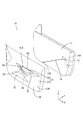
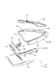
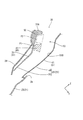
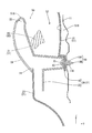
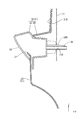
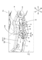
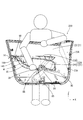
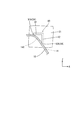
本発明の実施形態1に係る車両用ドアを示す斜視図The perspective view which shows the vehicle door which concerns on Embodiment 1 of this invention. ドアトリムを車室内側から視た平面図A plan view of the door trim as seen from the vehicle interior side 取付部材の分解斜視図Exploded perspective view of mounting member ドアトリムのドアグリップ付近の断面図(図2のIV−IV線で切断した図に対応)Sectional view of the door trim in the vicinity of the door grip (corresponding to the view cut along line IV-IV in FIG. 2) ドアトリムのプルハンドル付近の断面図(図2のV−V線で切断した図に対応)Sectional view near the pull handle of the door trim (corresponding to the view cut along the line V-V in FIG. 2) インサイドハンドル装置を模式的に示す説明図Explanatory drawing which shows an inside handle device typically 締結部を示す断面図(図6のVII−VII線で切断した図に対応)Sectional drawing which shows a fastening part (corresponding to the figure cut | disconnected by the VII-VII line of FIG. 6) 突出部を示す断面図(図6のVIII−VIII線で切断した図に対応)Sectional drawing which shows a protrusion part (corresponding to the figure cut | disconnected by the VIII-VIII line of FIG. 6) 後上締結部を示す断面図(図6のIX−IX線で切断した図に対応)Sectional drawing which shows a rear upper fastening part (corresponding to the figure cut | disconnected by the IX-IX line of FIG. 6) 本発明の実施形態2に係るインサイドハンドル装置を模式的に示す説明図Explanatory drawing which shows typically the inside handle apparatus which concerns on Embodiment 2 of this invention. 本発明の実施形態3に係るドアトリムを車室内側から視た平面図The top view which looked at the door trim which concerns on Embodiment 3 of this invention from the vehicle interior side ドアトリムを車室外側から視た平面図A plan view of the door trim viewed from the outside of the passenger compartment インサイドハンドル装置のガイド部付近を車両下方かつ車室外側から視た斜視図The perspective view which looked at the guide part vicinity of the inside handle device from the vehicle lower side and the passenger compartment outside インサイドハンドル装置のガイド部付近を車両上方かつ車室外側から視た斜視図The perspective view which looked at the guide part vicinity of an inside handle device from the vehicle upper direction and the vehicle interior outside ケーブルの取り付け態様を説明する説明図Explanatory drawing explaining the attachment mode of a cable 規制部を車室外側から視た平面図A plan view of the restriction section viewed from the outside of the passenger compartment 規制部を車両後方から視た側面図Side view of the restricting part viewed from the rear of the vehicle 本発明の実施形態4に係るドアトリムを示す斜視図The perspective view which shows the door trim which concerns on Embodiment 4 of this invention. インサイドハンドル装置を模式的に示す説明図(図18のIX−IX線で切断した図に対応)Explanatory drawing which shows an inside handle device typically (corresponding to the figure cut along line IX-IX in FIG. 18) 実施形態4の変形例1に係るドアトリムを示す斜視図The perspective view which shows the door trim which concerns on the modification 1 of Embodiment 4. FIG.

<実施形態1>
本発明の実施形態1を図1ないし図6によって説明する。本実施形態では、運転席の側方に配されたドアトリム(車両用ドアトリム)20について例示する。以下の説明では、図1のX軸方向を車両前後方向、Y軸方向を車幅方向(車室内外方向)、Z軸方向を上下方向として説明する。
<Embodiment 1>
A first embodiment of the present invention will be described with reference to FIGS. In this embodiment, the door trim (vehicle door trim) 20 arranged on the side of the driver's seat is illustrated. In the following description, the X-axis direction in FIG. 1 will be described as the vehicle longitudinal direction, the Y-axis direction as the vehicle width direction (the vehicle interior / exterior direction), and the Z-axis direction as the vertical direction.

ドアトリム20は、図1に示すように、車両用ドア10を構成するドアインナパネル(車体パネルの一例)11の車室内側に取り付けられ、車両用ドア10の車室内面10Aを構成するものである。ドアトリム20は、ドアインナパネル11を車室内側から覆うトリム本体部21を主体に構成されている。トリム本体部21は、トリムボード23と、後述する各種機能部品をトリムボード23に対して取り付けるための取付部材26とから少なくとも構成されている。なお、ドアトリム20は、取付部材26によって取り付けられる機能部品以外にも、ドアポケット16やスピーカグリル(不図示)といった機能部品を更に備えている。   As shown in FIG. 1, the door trim 20 is attached to the vehicle interior side of a door inner panel (an example of a vehicle body panel) 11 constituting the vehicle door 10, and constitutes a vehicle interior surface 10 </ b> A of the vehicle door 10. is there. The door trim 20 is mainly configured by a trim main body 21 that covers the door inner panel 11 from the vehicle interior side. The trim main body 21 includes at least a trim board 23 and an attachment member 26 for attaching various functional parts to be described later to the trim board 23. The door trim 20 further includes functional parts such as a door pocket 16 and a speaker grill (not shown) in addition to the functional parts attached by the attachment member 26.

また、ドアトリム20は、図1に示すように、ドアグリップ50、スイッチベース60、プルハンドル70、インサイドハンドル装置80といった各種機能部品を備えている。これらの機能部品は、その機能を発揮する上で、いずれも乗員が手を掛けたり、手で操作したりする部品であり、その使用性を向上するうえで、乗員の手の届き易い位置に配することが好ましい部品であると言える。以下、トリムボード23、取付部材26、各種機能部品について順次に説明する。   Further, as shown in FIG. 1, the door trim 20 includes various functional parts such as a door grip 50, a switch base 60, a pull handle 70, and an inside handle device 80. These functional parts are parts that the occupant puts on and operates by hand in order to perform their functions.In order to improve the usability, these functional parts are easily accessible. It can be said that it is a preferable part to arrange. Hereinafter, the trim board 23, the mounting member 26, and various functional parts will be described in order.

トリムボード23は、図2に示すように、例えば、ポリプロピレン等の合成樹脂材料によって構成された板状の部材とされる。なお、トリムボード23の材質は、合成樹脂材料に限定されず、例えば、木質系材料(例えば、ケナフ、ヘンプ、フラックス、サイザルなど)と合成樹脂を混合したものなどを用いてもよい。また、トリムボード23は、メインボードとオーナメント等の複数のボード部材を互いに組み付ける形で構成されていてもよい。トリムボード23には、その中央部、つまり運転席に着座した乗員の前腕部付近に位置して、平面視逆三角形状の開口部24が形成されている。この開口部24には、取付部材26が配設されている。   As shown in FIG. 2, the trim board 23 is a plate-like member made of a synthetic resin material such as polypropylene. The material of the trim board 23 is not limited to a synthetic resin material. For example, a material obtained by mixing a woody material (for example, kenaf, hemp, flux, sisal, etc.) and a synthetic resin may be used. Further, the trim board 23 may be configured by assembling a plurality of board members such as a main board and an ornament. The trim board 23 is formed with an opening 24 having an inverted triangular shape in plan view, located in the center thereof, that is, in the vicinity of the forearm portion of the passenger seated in the driver's seat. An attachment member 26 is disposed in the opening 24.

取付部材26は、図3に示すように、第1部材30と、第1部材30の車室外側に配される第2部材40とで構成されている。本実施形態では、第1部材30が、平面視V字状の板状部材とされるとともに、第2部材40が、平面視逆三角形状の板状部材とされるものを例示する。第1部材30と第2部材40とは、第2部材40の下部に、車室内側から第1部材30が重なる形で、互いに組み付けられている。なお、第1部材30は、これと同様の外形をなす加飾パネル28によって更に車室内側から覆われている。この取付部材26は、開口部24を閉塞する形でトリムボード23に取り付けられる。   As shown in FIG. 3, the attachment member 26 includes a first member 30 and a second member 40 disposed on the outside of the passenger compartment of the first member 30. In the present embodiment, the first member 30 is a plate-like member having a V shape in plan view, and the second member 40 is a plate-like member having an inverted triangular shape in plan view. The 1st member 30 and the 2nd member 40 are mutually assembled | attached to the lower part of the 2nd member 40 so that the 1st member 30 may overlap from the vehicle interior side. In addition, the 1st member 30 is further covered from the vehicle interior side by the decorating panel 28 which makes the external shape similar to this. The attachment member 26 is attached to the trim board 23 so as to close the opening 24.

第1部材30は、図3に示すように、ドアグリップ50の相対的に車室内側に位置する部分を構成する第1ドアグリップ用挿入壁部31と、プルハンドル70の相対的に車室内側に位置する部分を構成する第1プルハンドル用挿入壁部32と、を備えている。第1ドアグリップ用挿入壁部31は、V字状をなす第1部材30の車両前方に向かうにつれて上昇する部分に設けられている。また、第1プルハンドル用挿入壁部32は、V字状をなす第1部材30の車両後方に向かうにつれて緩やかに上昇する部分に設けられている。そして、第1部材30には、第1ドアグリップ用挿入壁部31と第1プルハンドル用挿入壁部32の間に位置する角部33に、インサイドハンドル装置80の回動軸81が突設されている(図5参照)。   As shown in FIG. 3, the first member 30 includes a first door grip insertion wall portion 31 that forms a portion of the door grip 50 that is positioned relatively on the vehicle interior side, and a pull handle 70 relative to the vehicle interior. A first pull handle insertion wall portion 32 constituting a portion located on the inner side. The first door grip insertion wall portion 31 is provided on a portion of the V-shaped first member 30 that rises toward the front of the vehicle. Further, the first pull handle insertion wall portion 32 is provided at a portion of the V-shaped first member 30 that gently rises toward the rear of the vehicle. A rotation shaft 81 of the inside handle device 80 projects from the first member 30 at a corner 33 located between the first door grip insertion wall 31 and the first pull handle insertion wall 32. (See FIG. 5).

第2部材40は、図3に示すように、ドアグリップ50の相対的に車室外側に位置する部分を構成する第2ドアグリップ用挿入壁部41と、プルハンドル70の相対的に車室外側に位置する部分を構成する第2プルハンドル用挿入壁部42と、を備えている。第2ドアグリップ用挿入壁部41は、逆三角形状をなす第2部材40の車両前側辺部に設けられている。また、第2プルハンドル用挿入壁部42は、逆三角形状をなす第2部材40の車両後側辺部に設けられている。第2部材40には、車両上側辺部において、スイッチベース60が取り付けられるスイッチベース取付部43が設けられている。スイッチベース取付部43は、車室内側に張り出す形で構成されている。また、第2部材40は、その中央部が車両前後方向かつ車両上下方向に沿って延在するとともに、トリムボード23の開口部24から車室内に露出して、車室内面10Aを構成する取付部材側意匠面44とされている。   As shown in FIG. 3, the second member 40 includes a second door grip insertion wall portion 41 that forms a portion of the door grip 50 that is located relatively outside the vehicle compartment, and a relatively vehicle compartment of the pull handle 70. And a second pull handle insertion wall portion 42 that constitutes a portion located outside. The insertion wall part 41 for 2nd door grips is provided in the vehicle front side part of the 2nd member 40 which makes | forms an inverted triangle shape. Further, the second pull handle insertion wall portion 42 is provided on the vehicle rear side portion of the second member 40 having an inverted triangular shape. The second member 40 is provided with a switch base attachment portion 43 to which the switch base 60 is attached on the upper side portion of the vehicle. The switch base mounting portion 43 is configured to project to the vehicle interior side. Further, the second member 40 has a central portion extending in the vehicle front-rear direction and the vehicle vertical direction, and is exposed to the vehicle interior from the opening 24 of the trim board 23 to constitute a vehicle interior surface 10A. The member-side design surface 44 is used.

ドアグリップ50は、図4に示すように、ドアグリップ用挿入壁部51と、ドアグリップ用挿入壁部51の車室内側において、把持可能に設けられたドアグリップ用把持部(把持部の一例)55と、を備えて構成されている。ドアグリップ50は、例えば、乗員が姿勢を保持する際等に把持可能な構成とされる。また、本実施形態では、ドアグリップ用把持部55に隣接してインサイドハンドル装置80のハンドル部83が設けられており、ドアグリップ50は、インサイドハンドル装置80のハンドル部83に手を掛けた状態で把持可能とされている。つまり、ドアグリップ50は、車両用ドア10を開ける際に、好適にこれを把持して車両用ドア10を操作可能な構成とされており、車両用ドア10を操作するための第1の操作部とも言える。   As shown in FIG. 4, the door grip 50 includes a door grip insertion wall portion 51 and a door grip grip portion (an example of a grip portion) provided on the vehicle interior side of the door grip insertion wall portion 51. 55). The door grip 50 is configured to be gripped when, for example, the occupant holds a posture. In the present embodiment, the handle portion 83 of the inside handle device 80 is provided adjacent to the door grip grip portion 55, and the door grip 50 is in a state where the handle portion 83 of the inside handle device 80 is put on the hand. It can be gripped with. That is, the door grip 50 is configured to be able to operate the vehicle door 10 by preferably holding the door 10 when the vehicle door 10 is opened, and a first operation for operating the vehicle door 10. It can be said to be a part.

ドアグリップ用挿入壁部51は、図4に示すように、車両上方かつ車両後方に向けて開口するとともに、内部に手指を挿入可能なドアグリップ用挿入空間53を有する。ドアグリップ用挿入壁部51は、第1部材30の第1ドアグリップ用挿入壁部31と、第2部材40の第2ドアグリップ用挿入壁部41とを組み付けてなり、両壁部31,41の間にドアグリップ用挿入空間53が画成される。なお、図3においては図示を省略するが、ドアグリップ用挿入空間53は、底面がドアグリップ用挿入壁部51とは別の部材(不図示)で閉塞されることで有底凹状に構成されている。   As shown in FIG. 4, the door grip insertion wall portion 51 has an opening space 53 for door grip into which the fingers can be inserted while opening upward and toward the rear of the vehicle. The door grip insertion wall portion 51 is formed by assembling the first door grip insertion wall portion 31 of the first member 30 and the second door grip insertion wall portion 41 of the second member 40. A door grip insertion space 53 is defined between 41. Although not shown in FIG. 3, the door grip insertion space 53 is configured to have a bottomed concave shape by closing the bottom surface with a member (not shown) different from the door grip insertion wall 51. ing.

ドアグリップ用把持部55は、図4に示すように、ドアグリップ用挿入空間53に手指を挿入する形で把持可能な構成とされる。ドアグリップ用把持部55は、第1ドアグリップ用挿入壁部31の上端部51Aに形成されている。上端部51Aは、その他の部分より板厚が大きく設定され、ハンドル部83と隣接する部分においては、一部車室外側に張り出して、ハンドル部83の上方に重なる形とされている。   As shown in FIG. 4, the door grip grip portion 55 is configured to be gripped by inserting a finger into the door grip insertion space 53. The door grip grip 55 is formed on the upper end 51 </ b> A of the first door grip insertion wall 31. The upper end 51 </ b> A is set to have a larger thickness than the other portions, and in a portion adjacent to the handle portion 83, a part of the upper end portion 51 </ b> A protrudes outside the vehicle compartment and overlaps the handle portion 83.

スイッチベース60は、図3及び図5に示すように、車両前後方向かつ車室内外方向に沿って延在する板状部材とされ、板面に開口する形でスイッチ操作部61A(図2参照)が配されるスイッチ用開口61を有している。詳細には、スイッチベース60は、第2部材40の車両上側辺部の車両前端部から車両後端部にまで延設され、取付部材26の上端部を覆う加飾パネルのような役目を果たしている。スイッチベース60は、スイッチベース取付部43に対して、例えば、爪嵌合等の取付手段により取り付けられている。スイッチ操作部61Aは、例えば、車両用ドア10に装備された電装部品を駆動するためのものとされ、ウインドウレギュレータの駆動スイッチ等である。   As shown in FIGS. 3 and 5, the switch base 60 is a plate-like member extending in the vehicle front-rear direction and in the vehicle interior-exterior direction, and is open to the plate surface so that the switch operation portion 61A (see FIG. 2) ) Is provided in the switch opening 61. Specifically, the switch base 60 extends from the vehicle front end portion of the second member 40 on the vehicle upper side portion to the vehicle rear end portion, and serves as a decorative panel that covers the upper end portion of the mounting member 26. Yes. The switch base 60 is attached to the switch base attachment portion 43 by attachment means such as claw fitting, for example. The switch operation unit 61A is, for example, for driving electrical components mounted on the vehicle door 10, and is a drive switch for a window regulator or the like.

プルハンドル70は、図5に示すように、プルハンドル用挿入壁部71と、プルハンドル用挿入壁部71の車室内側において、把持可能に設けられたプルハンドル用把持部75と、を備えて構成されている。プルハンドル70は、例えば、後述するプルハンドル用挿入空間73に手指を挿入して、車両用ドア10を開閉操作可能な構成とされている。つまり、プルハンドル70は、車両用ドア10を操作するための第2の操作部とも言える。本実施形態では、プルハンドル70は、ドアグリップ50より車両後方、つまり、一般的なヒンジ式の車両用ドア10において、第1の操作部であるドアグリップ50より開閉時の回動軸より遠い位置に配されているから、低い荷重でもって車両用ドア10を操作可能とされる。   As shown in FIG. 5, the pull handle 70 includes a pull handle insertion wall portion 71 and a pull handle grip portion 75 provided to be grippable on the vehicle interior side of the pull handle insertion wall portion 71. Configured. For example, the pull handle 70 is configured to be able to open and close the vehicle door 10 by inserting a finger into a pull handle insertion space 73 described later. That is, it can be said that the pull handle 70 is a second operation unit for operating the vehicle door 10. In the present embodiment, the pull handle 70 is located behind the door grip 50, that is, farther from the pivot shaft at the time of opening and closing than the door grip 50, which is the first operation unit, in the general hinge-type vehicle door 10. Since it is arranged at the position, the vehicle door 10 can be operated with a low load.

プルハンドル用挿入壁部71は、図5に示すように、車両上方に向けて開口するとともに、内部に手指を挿入可能なプルハンドル用挿入空間(挿入空間の一例)73を有する。プルハンドル用挿入壁部71は、第1部材30の第1プルハンドル用挿入壁部32と、第2部材40の第2プルハンドル用挿入壁部42とを組み付けてなり、両壁部32,42の間に有底凹状のプルハンドル用挿入空間73が画成される。   As shown in FIG. 5, the pull handle insertion wall portion 71 has an opening space (an example of an insertion space) 73 that opens toward the top of the vehicle and into which fingers can be inserted. The pull handle insertion wall portion 71 is formed by assembling the first pull handle insertion wall portion 32 of the first member 30 and the second pull handle insertion wall portion 42 of the second member 40. An insertion space 73 with a bottomed concave pull handle is defined between 42.

プルハンドル用把持部75は、図5に示すように、プルハンドル用挿入空間73に手指を挿入する形で把持可能な構成とされる。プルハンドル用把持部75は、第1プルハンドル用挿入壁部32が、プルハンドル用挿入空間73の開口縁において、車室内側に屈曲する形で構成されている。プルハンドル用把持部75の上面75Aは、水平方向に対して緩やかに傾斜する形で延在し、アームレスト17としての役目を果たす。   As shown in FIG. 5, the pull handle gripping portion 75 is configured to be gripped by inserting a finger into the pull handle insertion space 73. The pull handle grip portion 75 is configured such that the first pull handle insertion wall portion 32 is bent toward the vehicle interior side at the opening edge of the pull handle insertion space 73. The upper surface 75A of the pull handle gripping portion 75 extends so as to be gently inclined with respect to the horizontal direction and serves as the armrest 17.

ところで、車両用ドア10には、図1に示すように、ドアインナパネル11とドアアウタパネル(不図示)との間に、当該車両用ドア10を閉じた状態でロックするロック装置13が設けられている。ロック装置13には、ケーブル14の一端部14Aが接続されている。ケーブル14は、ドアインナパネル11を貫通して、ドアインナパネル11の車室内側かつドアトリム20の車室外側に導出され、その他端部14Bがインサイドハンドル装置80に接続される。このような構成により、ロック装置13は、車室内からインサイドハンドル装置80を操作して、ロック状態を解除可能とされている。   Incidentally, as shown in FIG. 1, the vehicle door 10 is provided with a lock device 13 that locks the vehicle door 10 in a closed state between the door inner panel 11 and a door outer panel (not shown). ing. One end portion 14 </ b> A of a cable 14 is connected to the lock device 13. The cable 14 passes through the door inner panel 11, is led out to the vehicle interior side of the door inner panel 11 and the vehicle exterior side of the door trim 20, and the other end 14 </ b> B is connected to the inside handle device 80. With such a configuration, the lock device 13 can be released from the locked state by operating the inside handle device 80 from the vehicle interior.

インサイドハンドル装置80は、図5及び図6に示すように、車室内外方向に沿って延びる形で取付部材26に設けられた回動軸81と、回動軸81から車両前方に向けて延出した長尺レバー状のハンドル部83と、回動軸81から車両後方に向けて延出して、ケーブル14の他端部14Bが係止される係止部85と、を備えている。インサイドハンドル装置80は、ハンドル部83、回動軸81、及び係止部85がそれぞれ力点、支点、及び作用点とされる第1種てこのような態様となっている。   As shown in FIGS. 5 and 6, the inside handle device 80 includes a turning shaft 81 provided on the attachment member 26 in a form extending along the outside of the vehicle interior, and extends from the turning shaft 81 toward the front of the vehicle. A long lever-like handle portion 83 is provided, and a locking portion 85 extending from the rotating shaft 81 toward the rear of the vehicle and locking the other end portion 14B of the cable 14 is provided. The inside handle device 80 has such a first type in which the handle portion 83, the rotation shaft 81, and the locking portion 85 are a force point, a fulcrum, and an action point, respectively.

回動軸81は、図5に示すように、第1部材30の車室外側面に突設されている。また、回動軸81は、その車室外側の端部を支持する支持部材82によって、第1部材30に対して移動不能に固定されている。回動軸81は、ドアグリップ用挿入壁部51とプルハンドル用挿入壁部71の間において、トリム本体部21の車室外側に配されている。   As shown in FIG. 5, the rotation shaft 81 protrudes from the outer surface of the first member 30. Further, the rotation shaft 81 is fixed so as not to move with respect to the first member 30 by a support member 82 that supports an end portion outside the passenger compartment. The pivot shaft 81 is disposed outside the trim body 21 between the door grip insertion wall 51 and the pull handle insertion wall 71.

ハンドル部83は、図4及び図6に示すように、待機位置P1と、待機位置P1から回動軸81を中心として車両上方に向けて回動することで、ロック装置13による車両用ドア10のロック状態を解除可能な解除位置P2と、の間で回動可能な構成とされている。なお、ハンドル部83は、解除位置P2から待機位置P1に復帰可能なように、トーションバネ等の弾性部材によって車両下方に付勢されている。   As shown in FIGS. 4 and 6, the handle portion 83 is rotated toward the vehicle upper position around the rotation axis 81 from the standby position P <b> 1 and the standby position P <b> 1, whereby the vehicle door 10 by the lock device 13. It is set as the structure which can be rotated between the cancellation | release positions P2 which can cancel | release this locked state. The handle portion 83 is urged downward in the vehicle by an elastic member such as a torsion spring so that the handle portion 83 can be returned from the release position P2 to the standby position P1.

続いて、ドアグリップ50、スイッチベース60、プルハンドル70、及びインサイドハンドル装置80の配置構成について説明する。
スイッチベース60とインサイドハンドル装置80とプルハンドル70は、図2に示すように、インサイドハンドル装置80及びプルハンドル70の車両上方にスイッチベース60が位置するようにして、取付部材26の周縁部26Aにそれぞれ配されている。つまり、スイッチベース60とインサイドハンドル装置80とプルハンドル70は、ドアトリム20の開口部24を囲むようにして配されている。また、ドアグリップ50とプルハンドル70とは、ドアグリップ50の車両後方にプルハンドル70が位置するとともに、そのドアグリップ用把持部55とプルハンドル用把持部75とがV字状に交差するようにしてそれぞれ延設されている。ドアトリム20は、図5に示すように、車両上下方向については、スイッチベース60が車室内側に向けて膨出するとともに、その車両下方において、プルハンドル70が車室内側に向けて膨出する、2つの膨出形状を有している。このような構成により、ドアトリム20は、例えば、プルハンドルの車両前方にスイッチベースが配された1つの膨出形状を有する一般的なドアトリムの意匠と相違した、斬新な意匠を呈する。
Next, the arrangement configuration of the door grip 50, the switch base 60, the pull handle 70, and the inside handle device 80 will be described.
As shown in FIG. 2, the switch base 60, the inside handle device 80, and the pull handle 70 are arranged so that the switch base 60 is positioned above the inside handle device 80 and the pull handle 70 in the vehicle. Are arranged respectively. That is, the switch base 60, the inside handle device 80, and the pull handle 70 are arranged so as to surround the opening 24 of the door trim 20. Further, the door grip 50 and the pull handle 70 are arranged such that the pull handle 70 is located behind the door grip 50 in the vehicle, and the door grip holding portion 55 and the pull handle holding portion 75 intersect in a V shape. Each of them is extended. As shown in FIG. 5, the door trim 20 has the switch base 60 bulges toward the vehicle interior side in the vehicle vertical direction, and the pull handle 70 bulges toward the vehicle interior side below the vehicle. It has two bulge shapes. With such a configuration, the door trim 20 exhibits a novel design that is different from, for example, a general door trim design having a single bulging shape in which a switch base is disposed in front of the pull handle on the vehicle.

インサイドハンドル装置80は、図2及び図6に示すように、トリム本体部21の中央部において、取付部材26(第1部材30)の角部33付近に配されている。そして、インサイドハンドル装置80は、ハンドル部83がドアグリップ用挿入空間53内に位置するとともに、係止部85がドアグリップ用挿入壁部51における車室外側に位置する奥壁51Bに沿ってトリム本体部21の車室外側に延出する形で配されている。ハンドル部83は、ドアグリップ用把持部55の車室外側に配されている。言い換えれば、ハンドル部83は、ドアグリップ用把持部55によって車室内側から覆われている。また、係止部85は、ドアグリップ用挿入壁部51とプルハンドル用挿入壁部71との間において、トリム本体部21とドアインナパネル11との間に配されている。   As shown in FIGS. 2 and 6, the inside handle device 80 is disposed near the corner portion 33 of the attachment member 26 (first member 30) in the central portion of the trim main body portion 21. In the inside handle device 80, the handle portion 83 is positioned in the door grip insertion space 53, and the locking portion 85 is trimmed along the rear wall 51B positioned outside the vehicle compartment in the door grip insertion wall portion 51. The main body portion 21 is arranged so as to extend outside the passenger compartment. The handle portion 83 is disposed outside the passenger compartment of the door grip grip portion 55. In other words, the handle portion 83 is covered from the vehicle interior side by the door grip grip portion 55. The locking portion 85 is disposed between the trim main body portion 21 and the door inner panel 11 between the door grip insertion wall portion 51 and the pull handle insertion wall portion 71.

続いて、ドアグリップ50、スイッチベース60、プルハンドル70、及びインサイドハンドル装置80の取り付け構成について説明する。
上述したように、ドアグリップ50とスイッチベース60とプルハンドル70とインサイドハンドル装置80は、一の取付部材26に対してそれぞれ設けられることで一体的に構成されている。つまり、取付部材26のトリムボード23への組み付けに先立って、ドアグリップ50、スイッチベース60、プルハンドル70、及びインサイドハンドル装置80が、取付部材26に対して予め組み付けられて、サブアッセンブリー化されている。なお、スイッチベース60については、その構成上、取付部材26をトリムボード23に対して取り付けた後に、取付部材26に対して取り付けることも可能である。
Next, the mounting configuration of the door grip 50, the switch base 60, the pull handle 70, and the inside handle device 80 will be described.
As described above, the door grip 50, the switch base 60, the pull handle 70, and the inside handle device 80 are integrally configured by being provided for one mounting member 26. That is, prior to assembling the mounting member 26 to the trim board 23, the door grip 50, the switch base 60, the pull handle 70, and the inside handle device 80 are assembled in advance to the mounting member 26 and are sub-assembled. ing. The switch base 60 can be attached to the attachment member 26 after the attachment member 26 is attached to the trim board 23 due to its configuration.

そして、一体的に構成されたドアグリップ50、スイッチベース60、プルハンドル70、及びインサイドハンドル装置80は、図5に示すように、取付部材26を介してトリムボード23に取り付けられている。詳細には、取付部材26は、車室外側の面に複数の取付ボス26Bが立設されており、取付ボス26Bがトリムボード23の開口部24の孔縁に設けられた取付孔24Aに対して熱カシメされることで、トリムボード23に取り付けられている。すると、自ずと、ドアグリップ50、スイッチベース60、プルハンドル70、及びインサイドハンドル装置80がトリムボード23に取り付けられた状態となる。このような態様により、各種機能部品を備えたドアトリム20が構成される。   The integrally configured door grip 50, switch base 60, pull handle 70, and inside handle device 80 are attached to the trim board 23 via an attachment member 26 as shown in FIG. Specifically, the mounting member 26 has a plurality of mounting bosses 26 </ b> B standing on the outer surface of the passenger compartment, and the mounting bosses 26 </ b> B with respect to mounting holes 24 </ b> A provided at the hole edges of the opening 24 of the trim board 23. By being caulked with heat, the trim board 23 is attached. Then, the door grip 50, the switch base 60, the pull handle 70, and the inside handle device 80 are naturally attached to the trim board 23. By such an aspect, the door trim 20 provided with various functional components is comprised.

その後、ドアトリム20は、ドアインナパネル11に対して締結部材19やクリップ(不図示)等の締結部材を介して取り付けられる。ドアトリム20のうち、取付部材26は次のような態様でドアインナパネル11に対して取り付けられる。   Thereafter, the door trim 20 is attached to the door inner panel 11 through a fastening member such as a fastening member 19 or a clip (not shown). Of the door trim 20, the attachment member 26 is attached to the door inner panel 11 in the following manner.

取付部材26は、図6に示すように、ドアインナパネル11に対して締結される締結部35、前上締結部36、及び後上締結部37と、車室外側に向けて突出する突出部38を有している。各締結部35,36,37は、締結部材19を挿通可能な孔部とされ、締結部材19を介してドアインナパネル11に締結されている(図7及び図9参照)。締結部材19は、ネジ式クリップ19Aと、ネジ式クリップ19Aに螺合して、これを拡径変形させるネジ19Bと、で構成されている。ドアインナパネル11には各締結部35,36,37と連通する位置に締結部材用貫通孔11Aが形成されている。そして、締結部材用貫通孔11Aに、ネジ式クリップ19Aを挿通し、各締結部35,36,37を介して車室内側からネジ式クリップ19Aにネジ19Bを螺合することで、各締結部35,36,37をドアインナパネル11に対して締結可能となっている。なお、本実施形態では、取付部材26のうち第1部材30に締結部35、前上締結部36、及び後上締結部37が形成され、これらと連通する形で第2部材40にそれぞれ締結部45,46,47が形成されており、第1部材30と第2部材40とが、ドアインナパネル11に対して共締めされている。また、後上締結部37においては、取付部材26とトリムボード23とが、ドアインナパネル11に対して共締めされている(図9参照)。一方、突出部38は、第1部材30において、第2部材40と重ならない位置に設けられている(図8参照)。   As shown in FIG. 6, the attachment member 26 includes a fastening portion 35 fastened to the door inner panel 11, a front upper fastening portion 36, a rear upper fastening portion 37, and a protruding portion that protrudes toward the outside of the passenger compartment. 38. Each fastening part 35, 36, 37 is a hole through which the fastening member 19 can be inserted, and is fastened to the door inner panel 11 via the fastening member 19 (see FIGS. 7 and 9). The fastening member 19 includes a screw-type clip 19A and a screw 19B that is screwed into the screw-type clip 19A and expands and deforms the diameter. The door inner panel 11 has fastening member through holes 11 </ b> A formed at positions communicating with the fastening portions 35, 36, and 37. Then, the screw-type clip 19A is inserted into the through-hole 11A for the fastening member, and the screw 19B is screwed into the screw-type clip 19A from the vehicle interior side via the respective fastening portions 35, 36, and 37, so that each fastening portion 35, 36, and 37 can be fastened to the door inner panel 11. In the present embodiment, a fastening portion 35, a front upper fastening portion 36, and a rear upper fastening portion 37 are formed on the first member 30 of the attachment member 26, and are fastened to the second member 40 in a form communicating with them. Portions 45, 46 and 47 are formed, and the first member 30 and the second member 40 are fastened together with the door inner panel 11. Moreover, in the rear upper fastening part 37, the attachment member 26 and the trim board 23 are fastened together with the door inner panel 11 (refer FIG. 9). On the other hand, the protrusion part 38 is provided in the position which does not overlap with the 2nd member 40 in the 1st member 30 (refer FIG. 8).

締結部35は、図6に示すように、インサイドハンドル装置80の回動軸81に対して、解除位置P2に至るハンドル部83の回動方向(図6の矢印の方向)とは反対側に位置する。言い換えれば、締結部35は、回動軸81に対して解除位置P2におけるハンドル部83の長手方向と交差する方向かつ車両下方に位置する。具体的には、解除位置P2におけるハンドル部83の長手方向は、車両前後方向に対して40°〜70°程度傾斜しており、締結部35は、これと略直交する方向かつ車両下方、つまり、回動軸81に対して車両前方かつ下方に、回動軸81と近接して配されている。   As shown in FIG. 6, the fastening portion 35 is on the opposite side of the rotation direction (direction of the arrow in FIG. 6) of the handle portion 83 reaching the release position P <b> 2 with respect to the rotation shaft 81 of the inside handle device 80. To position. In other words, the fastening portion 35 is located in the direction intersecting the longitudinal direction of the handle portion 83 at the release position P2 with respect to the rotation shaft 81 and below the vehicle. Specifically, the longitudinal direction of the handle portion 83 at the release position P2 is inclined by about 40 ° to 70 ° with respect to the vehicle front-rear direction, and the fastening portion 35 is in a direction substantially orthogonal to this and below the vehicle, that is, The rotating shaft 81 is disposed in front of and below the vehicle in the vicinity of the rotating shaft 81.

突出部38は、図6に示すように、回動軸81に対して締結部35の反対側に位置する。言い換えれば、突出部38は、回動軸81に対して解除位置P2におけるハンドル部83の長手方向と交差する方向(略直交する方向)かつ車両上方、つまり、車両後方かつ上方に位置する。さらに言い換えれば、突出部38は、締結部35との間に回動軸81が介在するような位置に、回動軸81と近接して配されている。   As shown in FIG. 6, the protruding portion 38 is located on the opposite side of the fastening portion 35 with respect to the rotating shaft 81. In other words, the projecting portion 38 is located in a direction (substantially orthogonal) intersecting the longitudinal direction of the handle portion 83 at the release position P2 with respect to the rotation shaft 81 and above the vehicle, that is, behind and above the vehicle. In other words, the protruding portion 38 is disposed in the vicinity of the rotating shaft 81 at a position where the rotating shaft 81 is interposed between the protruding portion 38 and the fastening portion 35.

突出部38は、図8に示すように、ドアインナパネル11に貫通形成された突出部用貫通孔(貫通孔の一例)11Bに挿通されることで、取付部材26(その第1部材30)がドアインナパネル11のパネル面方向(XZ方向)に変位することを規制可能な構成とされる。具体的には、突出部38は、その側方に車室外側に向かうにつれて先細る側方リブ38Aを有しており、側方リブ38Aが突出部用貫通孔11Bの内周面に当接する態様で突出部用貫通孔11Bに挿通されている。このような態様により、突出部38は突出部用貫通孔11Bに対して径方向にガタつくことが抑制されている。   As shown in FIG. 8, the protruding portion 38 is inserted into a protruding portion through-hole (an example of a through-hole) 11 </ b> B formed through the door inner panel 11, thereby mounting member 26 (the first member 30). Is configured to be capable of restricting displacement in the panel surface direction (XZ direction) of the door inner panel 11. Specifically, the protruding portion 38 has side ribs 38A that taper toward the outside of the passenger compartment on the sides thereof, and the side ribs 38A abut against the inner peripheral surface of the protruding portion through-hole 11B. It is inserted in the through-hole 11B for protrusions by the aspect. By such an aspect, the protruding portion 38 is prevented from rattling in the radial direction with respect to the protruding portion through-hole 11B.

前上締結部36は、図6に示すように、締結部35の車両前方かつ上方に位置する。また、後上締結部37は、締結部35の車両後方かつ上方に位置する。そして、取付部材26は、締結部35と前上締結部36との間にドアグリップ用把持部55を有するとともに、締結部35と後上締結部37との間にプルハンドル用把持部75を有している。本実施形態では、V字状をなす第1部材30の角部33に回動軸81と締結部35が配されるとともに、両端部に前上締結部36と後上締結部37が配されている。また、本実施形態では、全体として略三角形状をなす取付部材26の各頂点に、締結部35、前上締結部36、後上締結部37が配されている。   As shown in FIG. 6, the front upper fastening portion 36 is located in front of and above the fastening portion 35 in the vehicle. Further, the rear upper fastening portion 37 is located behind and above the fastening portion 35 in the vehicle. The attachment member 26 has a door grip gripping portion 55 between the fastening portion 35 and the front upper fastening portion 36, and a pull handle gripping portion 75 between the fastening portion 35 and the rear upper fastening portion 37. Have. In the present embodiment, the rotation shaft 81 and the fastening portion 35 are disposed at the corner portion 33 of the V-shaped first member 30, and the front upper fastening portion 36 and the rear upper fastening portion 37 are disposed at both ends. ing. Moreover, in this embodiment, the fastening part 35, the front upper fastening part 36, and the rear upper fastening part 37 are distribute | arranged to each vertex of the attachment member 26 which makes a substantially triangular shape as a whole.

続いて、本実施形態の作用・効果について説明する。
本実施形態では、取付部材26の締結部35がドアインナパネル11に対して締結されるから、インサイドハンドル装置80の操作に伴って、取付部材26に作用する力をドアインナパネル11で受けることができる。このため、例えば、取付部材26がドアインナパネル11に対して締結されず、トリムボード23を介してドアインナパネル11に対して締結される構成に比べて、インサイドハンドル装置80の操作に伴って、取付部材26とトリムボード23との間でガタつきが生じたり、取付部材26とトリムボード23との組み付け状態が損なわれたりする事態の発生を抑制することができる。ところで、ハンドル部83の解除位置P2では、取付部材26における回動軸81が設けられた部位に、ハンドル部83の回動方向(図6の矢印の方向)に向かうような荷重が作用することが懸念される。本実施形態では、取付部材26において、ドアインナパネル11との締結部35を、回動軸81に対して、解除位置P2に至るハンドル部83の回動方向とは反対側に配することで、回動軸81が設けられた部位に上述のような力が作用したとしても、締結部35を中心とした回転モーメントが発生し難く、取付部材26に作用する荷重を締結部35で好適に受けることができる。このため、取付部材26の回動軸81が設けられた部位にハンドル部83の回動方向に向かうような荷重が作用したとしても、取付部材26とトリムボード23との間でガタつきが生じたり、取付部材26とトリムボード23の組み付け状態が損なわれたりする事態の発生を抑制することができる。
Then, the effect | action and effect of this embodiment are demonstrated.
In the present embodiment, since the fastening portion 35 of the mounting member 26 is fastened to the door inner panel 11, the door inner panel 11 receives a force acting on the mounting member 26 in accordance with the operation of the inside handle device 80. Can do. For this reason, for example, the attachment member 26 is not fastened to the door inner panel 11, and is compared with a configuration in which the mounting member 26 is fastened to the door inner panel 11 via the trim board 23, with the operation of the inside handle device 80. Further, it is possible to suppress the occurrence of a backlash between the mounting member 26 and the trim board 23 or the situation where the assembled state of the mounting member 26 and the trim board 23 is impaired. By the way, at the release position P2 of the handle portion 83, a load is applied to the portion of the attachment member 26 where the rotation shaft 81 is provided so as to be directed in the rotation direction of the handle portion 83 (the direction of the arrow in FIG. 6). Is concerned. In the present embodiment, in the attachment member 26, the fastening portion 35 with the door inner panel 11 is arranged on the opposite side to the turning direction of the handle portion 83 reaching the release position P <b> 2 with respect to the turning shaft 81. Even if the above-described force is applied to the portion where the rotation shaft 81 is provided, a rotational moment is hardly generated around the fastening portion 35, and the load acting on the mounting member 26 is suitably applied to the fastening portion 35. Can receive. For this reason, even if a load directed in the direction of rotation of the handle portion 83 acts on the portion of the mounting member 26 where the rotation shaft 81 is provided, rattling occurs between the mounting member 26 and the trim board 23. Or the situation in which the assembled state of the mounting member 26 and the trim board 23 is impaired can be suppressed.

ところで、ドアインナパネル11のようなパネル状の部材に対して取付部材26を締結する構成においては、一般的に、取付部材26は、ドアインナパネル11への締結方向(パネル面と直交する方向、Y軸方向)についてはガタつき難いが、ドアインナパネル11のパネル面の面方向(XZ方向)については、締結部材19を締結するために要するクリアランスの分だけガタつきが生じうる。このため、ハンドル部83が車両上方(図6の矢印の方向)、つまり、ドアインナパネル11のパネル面に沿って回動するような構成においては、取付部材26をドアインナパネル11に対して締結したとしても、取付部材26がドアインナパネル11のパネル面に沿ってガタつくことが懸念される。一方、本実施形態によれば、取付部材26において、回動軸81に対して締結部35の反対側の位置において突出部38が設けられているから、ハンドル部83からの力が作用する回動軸81が設けられた部位の両側において、取付部材26とドアインナパネル11をパネル面と直交する方向と、パネル面に沿った方向とで位置合わせすることができる。この結果、より一層好適に、取付部材26とトリムボード23との間でガタつきが生じる事態の発生を抑制することができる。   By the way, in the structure which fastens the attachment member 26 with respect to a panel-shaped member like the door inner panel 11, generally the attachment member 26 is the fastening direction to the door inner panel 11 (direction orthogonal to a panel surface). The Y-axis direction) is less likely to be rattled, but the panel surface direction (XZ direction) of the door inner panel 11 may be rattled by the clearance required to fasten the fastening member 19. For this reason, in the configuration in which the handle portion 83 rotates above the vehicle (in the direction of the arrow in FIG. 6), that is, along the panel surface of the door inner panel 11, the attachment member 26 is moved relative to the door inner panel 11. Even if fastened, there is a concern that the mounting member 26 may rattle along the panel surface of the door inner panel 11. On the other hand, according to the present embodiment, the mounting member 26 is provided with the protruding portion 38 at a position opposite to the fastening portion 35 with respect to the rotation shaft 81, so that the rotation from which the force from the handle portion 83 acts. On both sides of the portion where the moving shaft 81 is provided, the mounting member 26 and the door inner panel 11 can be aligned in a direction perpendicular to the panel surface and a direction along the panel surface. As a result, it is possible to more suitably suppress the occurrence of a backlash between the mounting member 26 and the trim board 23.

また、本実施形態では、取付部材26は、締結部35の車両前方かつ上方に位置して、ドアインナパネル11に対して締結される前上締結部36と、締結部35の車両後方かつ上方に位置して、ドアインナパネル11に対して締結される後上締結部37と、を有している。このため、取付部材26を互いに同一直線上に位置しない3点でドアインナパネル11に対して取り付けることができ、取付部材26をドアインナパネル11に対して安定的に取り付けることができる。   Further, in the present embodiment, the attachment member 26 is positioned in front of and above the fastening portion 35 in the vehicle, the front upper fastening portion 36 fastened to the door inner panel 11, and the vehicle rear and upward of the fastening portion 35. And a rear upper fastening portion 37 that is fastened to the door inner panel 11. For this reason, the attachment member 26 can be attached to the door inner panel 11 at three points not located on the same straight line, and the attachment member 26 can be stably attached to the door inner panel 11.

また、本実施形態では、取付部材26は、締結部35と前上締結部36との間に、把持可能なドアグリップ用把持部55を有し、ハンドル部83は、ドアグリップ用把持部55の車室外側に配されている。このため、ドアグリップ用把持部55を把持する際に取付部材26に係る荷重についても、締結部35と前上締結部36とで受けることができ、好ましい。また、ハンドル部83とドアグリップ用把持部55に、同時に手を掛けて車両用ドア10を開ける操作を行うことができ、例えば、ハンドル部とドアグリップ用把持部が離れた位置に配されることで、ハンドル部を引く操作と、車両用ドアを車室外に押す動作とを、両手で行うドアトリムに比べて、車両用ドア10を開ける際の操作性がよい。さらに、ハンドル部83を車室内から視認され難い位置に設けることができ、インサイドハンドル装置80を設けることに起因して、ドアトリム20の意匠性が損なわれる事態を抑制することができる。また、ハンドル部83が車室内側に向けて回動可能な態様とされる場合のように、車室内にその回動を許容するための空間を設ける必要がなく、ドアグリップ用把持部55の車室外側において、好適にハンドル部83を配置することができる。さらに、ハンドル部83が配されるドアグリップ用挿入空間53は、車両上方かつ車両後方に向けて開口しているから、車両上方に向けて開口することで、小物入れとしての利用し易いプルハンドル用挿入空間73に比べて、そのような用途で利用されることが少なく、常時にハンドル部83にアクセスし易い構成を実現することができる。   In the present embodiment, the attachment member 26 has a gripper 55 for gripping a door grip between the fastening portion 35 and the front upper fastening portion 36, and the handle portion 83 is for the doorgrip gripping portion 55. It is arranged outside the passenger compartment. For this reason, when the grip part 55 for door grips is hold | gripped, it can receive with the fastening part 35 and the front upper fastening part 36 also about the load concerning the attachment member 26, and is preferable. In addition, it is possible to perform an operation of opening the vehicle door 10 by simultaneously placing the hand on the handle portion 83 and the door grip grip portion 55. For example, the handle portion and the door grip grip portion are arranged at positions separated from each other. Thus, the operability when opening the vehicle door 10 is better than the door trim in which the operation of pulling the handle portion and the operation of pushing the vehicle door out of the passenger compartment are performed with both hands. Furthermore, the handle | steering-wheel part 83 can be provided in the position where it is hard to be visually recognized from a vehicle interior, and the situation where the design property of the door trim 20 is impaired by providing the inside handle apparatus 80 can be suppressed. Further, unlike the case where the handle portion 83 is configured to be rotatable toward the vehicle interior side, it is not necessary to provide a space for allowing the rotation in the vehicle interior. The handle portion 83 can be suitably disposed outside the passenger compartment. Furthermore, since the door grip insertion space 53 in which the handle portion 83 is disposed opens toward the vehicle upper side and the vehicle rear side, the pull handle that is easy to use as an accessory case can be opened by opening toward the vehicle upper side. Compared to the insertion space 73, it is rarely used for such purposes, and a configuration in which the handle portion 83 can be easily accessed can be realized.

また、本実施形態では、スイッチベース60とインサイドハンドル装置80とプルハンドル70が一の取付部材26に対して設けられているから、これらを一括して取り扱うことができ、例えば、各部をそれぞれトリムボード23に対して設ける場合に比べて、ドアトリム20の組み付け作業性に優れる。具体的には、ドアトリム20は、各種の機能部品を備える一方、それ自体が車両用ドア10の一部を構成する部品であり、車両用ドア10を製造する過程において、機能部品をドアトリム20に対していつ取り付けるかということが問題となる。例えば、インサイドハンドル装置80、プルハンドル70、ドアグリップ50といった、比較的大きな荷重を受けることが想定される機能部品については、ドアインナパネル11に対して締結されることが好ましく、従来、そのような機能部品は、ドアトリム20をドアインナパネル11に対して取り付ける際に、トリムボード23に対してそれぞれ組み付けられることが一般的であった。一方、本実施形態では、ドアトリム20をドアインナパネル11に対して取り付けるより前の段階、例えば、ドアトリム20を出荷する前の段階で、スイッチベース60、インサイドハンドル装置80、プルハンドル70、及びドアグリップ50をトリムボード23に対して取り付けた状態とすることができ、ドアトリム20をドアインナパネル11に対して取り付ける段階での各機能部品の取り付け作業を低減することができる。   In this embodiment, since the switch base 60, the inside handle device 80, and the pull handle 70 are provided with respect to one mounting member 26, they can be handled collectively, for example, each part is trimmed. Compared with the case where it is provided for the board 23, the assembling workability of the door trim 20 is excellent. Specifically, the door trim 20 includes various functional parts, and is a part that itself constitutes a part of the vehicle door 10. In the process of manufacturing the vehicle door 10, the functional part is used as the door trim 20. On the other hand, the question is when to install it. For example, functional parts such as the inside handle device 80, the pull handle 70, and the door grip 50 that are assumed to receive a relatively large load are preferably fastened to the door inner panel 11. Such functional parts are generally assembled to the trim board 23 when the door trim 20 is attached to the door inner panel 11. On the other hand, in the present embodiment, the switch base 60, the inside handle device 80, the pull handle 70, and the door at a stage before the door trim 20 is attached to the door inner panel 11, for example, before the door trim 20 is shipped. The grip 50 can be in a state of being attached to the trim board 23, and the work of attaching each functional component at the stage of attaching the door trim 20 to the door inner panel 11 can be reduced.

さらに、本実施形態では、スイッチベース60とインサイドハンドル装置80とプルハンドル70を一の取付部材26に対して設けることで、一体的な意匠を呈するものとすることができ、ドアトリム20の意匠性を向上することができる。また、取付部材26に設けられた各種機能部品がトリムボード23の開口部24内に集約されることにより、各部が散漫な印象を与え難くなっている。さらに、各種機能部品が集約されることにより、トリムボード23の上部(例えば、一般的にインサイドハンドル装置が配される前上部等)を、従来より車室外側に後退する形で薄型化することができ、すっきりとした意匠を実現可能となっている。   Furthermore, in this embodiment, by providing the switch base 60, the inside handle device 80, and the pull handle 70 with respect to one mounting member 26, an integrated design can be exhibited, and the design of the door trim 20 can be achieved. Can be improved. In addition, since various functional parts provided in the attachment member 26 are collected in the opening 24 of the trim board 23, it is difficult for each part to give a diffuse impression. In addition, by integrating various functional parts, the upper part of the trim board 23 (for example, the front upper part where the inside handle device is generally arranged) is made thinner so as to recede to the outside of the passenger compartment. It is possible to realize a clean design.

さらに、ドアトリム20において乗員の手が届き易い領域に、スイッチベース60のスイッチ操作部61Aと、インサイドハンドル装置80のハンドル部83と、プルハンドル70のプルハンドル用挿入空間73を位置させることができ、使用性に優れたドアトリム20を提供することができる。さらに、本実施形態では、ドアトリム20において乗員の手が届き易い領域(開口部24内)に、スイッチベース60のスイッチ操作部61Aと、インサイドハンドル装置80と、プルハンドル用挿入空間73を位置させることができ、使用性に優れたドアトリム20を提供することができる。具体的には、ドアトリム20において、乗員の姿勢を大きく変更することなく、手が届く領域は限られているが、取付部材26に設けられた各種機能部品が集約されることにより、機能部品の各々に手が届き易く、また、機能部品間で手を移動してこれらを操作することが容易である。   Further, the switch operating portion 61A of the switch base 60, the handle portion 83 of the inside handle device 80, and the pull handle insertion space 73 of the pull handle 70 can be positioned in an area that is easily reachable by the passenger in the door trim 20. The door trim 20 excellent in usability can be provided. Furthermore, in the present embodiment, the switch operating portion 61A of the switch base 60, the inside handle device 80, and the pull handle insertion space 73 are positioned in an area (in the opening 24) that is easily accessible by the passenger in the door trim 20. Thus, the door trim 20 excellent in usability can be provided. Specifically, in the door trim 20, the reachable area is limited without greatly changing the posture of the occupant, but the various functional parts provided on the mounting member 26 are integrated, so that It is easy to reach each of them, and it is easy to move them between the functional parts and operate them.

また、本実施形態では、ドアグリップ50とスイッチベース60とプルハンドル70は、ドアグリップ50の車両後方にプルハンドル70が位置するとともにドアグリップ50及びプルハンドル70の車両上方にスイッチベース60が位置するようにして、取付部材26の周縁部26Aにそれぞれ配されている。このため、一の取付部材26に対して各部をそれぞれ干渉することなく取り付けることができ好適である。また、ドアグリップ50及びプルハンドル70の車両上方にスイッチベース60が位置するから、一般的に車室内に膨出する形をなすドアグリップ50やプルハンドル70によってスイッチ操作部61Aが隠される事態の発生を抑制することができる。これらの結果、使用性に優れたドアトリム20を提供することができる。   In the present embodiment, the door grip 50, the switch base 60, and the pull handle 70 have the pull handle 70 positioned behind the door grip 50 and the switch base 60 positioned above the door grip 50 and pull handle 70. In this manner, the mounting member 26 is disposed on the peripheral edge portion 26A. For this reason, each part can be attached to one attachment member 26 without interfering with each other, which is preferable. Further, since the switch base 60 is positioned above the door grip 50 and the pull handle 70, the switch operating portion 61A is hidden by the door grip 50 and the pull handle 70 that are generally bulged into the vehicle interior. Occurrence can be suppressed. As a result, the door trim 20 excellent in usability can be provided.

また、本実施形態では、スイッチベース60とインサイドハンドル装置80とプルハンドル70は、インサイドハンドル装置80及びプルハンドル70の車両上方にスイッチベース60が位置するようにして、取付部材26の周縁部26Aにそれぞれ配されている。このため、一の取付部材26に対して各部をそれぞれ干渉することなく取り付けることができ好適である。また、プルハンドル70の車両上方にスイッチベース60が位置するから、一般的に車室内に膨出する形をなすプルハンドル70によってスイッチ操作部61Aが隠される事態の発生を抑制することができる。これらの結果、使用性に優れたドアトリム20を提供することができる。   In the present embodiment, the switch base 60, the inside handle device 80, and the pull handle 70 are arranged so that the switch base 60 is positioned above the inside handle device 80 and the pull handle 70 on the vehicle, and the peripheral portion 26 </ b> A of the mounting member 26. Are arranged respectively. For this reason, each part can be attached to one attachment member 26 without interfering with each other, which is preferable. Further, since the switch base 60 is located above the pull handle 70 in the vehicle, it is possible to suppress the occurrence of a situation in which the switch operating portion 61A is hidden by the pull handle 70 that is generally bulged into the vehicle interior. As a result, the door trim 20 excellent in usability can be provided.

<実施形態2>
次いで、本発明の実施形態2を、図10を参照しつつ説明する。本実施形態では、インサイドハンドル装置180の位置が相違するドアトリム20について例示する。なお、上記した実施形態と同様の構造、作用及び効果については同じ符号を付し、重複する説明は省略する。
<Embodiment 2>
Next, Embodiment 2 of the present invention will be described with reference to FIG. In this embodiment, it illustrates about the door trim 20 from which the position of the inside handle apparatus 180 differs. In addition, the same code | symbol is attached | subjected about the structure, an effect | action, and effect similar to above-described embodiment, and the overlapping description is abbreviate | omitted.

インサイドハンドル装置180は、トリム本体部21の中央部において、取付部材26(第1部材30)の車両後側の部分に配されている。そして、インサイドハンドル装置180は、ハンドル部83がプルハンドル用挿入空間73内に位置するとともに、係止部85がプルハンドル用挿入壁部71における車室外側に位置する奥壁51Bに沿ってトリム本体部21の車室外側に延出する形で配されている。ハンドル部83は、プルハンドル用把持部75(把持部の一例)の車室外側に配されている。言い換えれば、ハンドル部83は、プルハンドル用把持部75によって車室内側から覆われている。さらに言い換えれば、ハンドル部83は、例えば、プルハンドル用把持部75に親指を掛けた状態で、他の指をプルハンドル用挿入空間73に挿入して握ることが可能な位置に配されている。また、係止部85は、プルハンドル用挿入壁部71の車両後方において、トリム本体部21とドアインナパネル11との間に配されている。   The inside handle device 180 is disposed in the vehicle rear side portion of the attachment member 26 (first member 30) in the central portion of the trim main body portion 21. In the inside handle device 180, the handle portion 83 is positioned in the pull handle insertion space 73, and the locking portion 85 is trimmed along the rear wall 51B located outside the compartment in the pull handle insertion wall portion 71. The main body portion 21 is arranged so as to extend outside the passenger compartment. The handle portion 83 is disposed outside the passenger compartment of the pull handle grip portion 75 (an example of a grip portion). In other words, the handle portion 83 is covered from the vehicle interior side by the pull handle grip portion 75. Furthermore, in other words, the handle portion 83 is arranged at a position where another finger can be inserted into the pull handle insertion space 73 and grasped with the thumb on the pull handle grip portion 75, for example. . The locking portion 85 is disposed between the trim main body portion 21 and the door inner panel 11 at the vehicle rear side of the pull handle insertion wall portion 71.

取付部材26は、ドアインナパネル11に対して締結される締結部135、前上締結部136、及び後上締結部137と、車室外側に向けて突出する突出部138を有している。締結部135は、インサイドハンドル装置180の回動軸81に対して、解除位置P2に至るハンドル部83の回動方向(図10の矢印の方向)とは反対側に位置する。突出部138は、回動軸81に対して締結部135の反対側の位置に設けられている。また、取付部材26は、締結部135の車両前方かつ上方に位置して、ドアインナパネル11に対して締結される前上締結部136と、締結部135の車両後方かつ上方に位置して、ドアインナパネル11に対して締結される後上締結部137と、を有している。なお、本実施形態では、取付部材26は、角部33付近に、ドアインナパネル11に対して締結される角部側締結部139を更に有している。なお、締結部135,136,137及び突出部138は、その配置構成を除いては、実施形態1の締結部35,36,37及び突出部38はと同様の構成とされており、その説明を省略する。   The attachment member 26 has a fastening portion 135 fastened to the door inner panel 11, a front upper fastening portion 136, a rear upper fastening portion 137, and a protruding portion 138 that protrudes toward the outside of the passenger compartment. The fastening portion 135 is located on the opposite side of the turning direction of the handle portion 83 reaching the release position P2 (the direction of the arrow in FIG. 10) with respect to the turning shaft 81 of the inside handle device 180. The protruding portion 138 is provided at a position opposite to the fastening portion 135 with respect to the rotation shaft 81. Further, the mounting member 26 is positioned in front of and above the fastening portion 135 in the vehicle, and is positioned on the front upper fastening portion 136 fastened to the door inner panel 11 and in the vehicle rear and above the fastening portion 135, And a rear upper fastening portion 137 fastened to the door inner panel 11. In the present embodiment, the attachment member 26 further includes a corner side fastening portion 139 that is fastened to the door inner panel 11 in the vicinity of the corner portion 33. The fastening portions 135, 136, 137 and the protruding portion 138 are configured in the same manner as the fastening portions 35, 36, 37 and the protruding portion 38 of the first embodiment except for the arrangement configuration thereof. Is omitted.

本実施形態では、取付部材26は、締結部135と後上締結部137との間に、把持可能なプルハンドル用把持部175を有し、ハンドル部83は、プルハンドル用把持部75の車室外側に配されている。このため、プルハンドル用把持部75を把持する際に取付部材26に係る荷重についても、締結部135と後上締結部137で受けることができ、好ましい。また、ハンドル部83とプルハンドル用把持部75に、同時に手を掛けて車両用ドア10を開ける操作を行うことができ、例えば、ハンドル部とプルハンドル用把持部が離れた位置に配されることで、ハンドル部を引く操作と、車両用ドアを車室外に押す動作とを、両手で行うドアトリムに比べて、車両用ドア10を開ける際の操作性がよい。さらに、ハンドル部83を車室内から視認され難い位置に設けることができ、インサイドハンドル装置80を設けることに起因して、ドアトリム20の意匠性が損なわれる事態を抑制することができる。また、ハンドル部83が車室内側に向けて回動可能な態様とされる場合のように、車室内にその回動を許容するための空間を設ける必要がなく、プルハンドル用挿入空間73内において、好適にハンドル部83を配置することができる。さらに、ハンドル部83が配されるプルハンドル用挿入空間73は、ドアグリップ用挿入空間53に比べて車両用ドア10を操作する際の荷重が低減されているから、車両用ドア10を開け易い構成を実現することができる。   In the present embodiment, the attachment member 26 has a pull handle grip portion 175 that can be gripped between the fastening portion 135 and the rear upper fastening portion 137, and the handle portion 83 is a vehicle of the pull handle grip portion 75. It is arranged outside the room. For this reason, when the grip part 75 for pull handles is gripped, the load related to the attachment member 26 can be received by the fastening part 135 and the rear upper fastening part 137, which is preferable. Further, the handle portion 83 and the pull handle grip portion 75 can be simultaneously operated to open the vehicle door 10 and, for example, the handle portion and the pull handle grip portion are arranged at positions separated from each other. Thus, the operability when opening the vehicle door 10 is better than the door trim in which the operation of pulling the handle portion and the operation of pushing the vehicle door out of the passenger compartment are performed with both hands. Furthermore, the handle | steering-wheel part 83 can be provided in the position where it is hard to be visually recognized from a vehicle interior, and the situation where the design property of the door trim 20 is impaired by providing the inside handle apparatus 80 can be suppressed. Further, unlike the case in which the handle portion 83 is configured to be rotatable toward the vehicle interior side, it is not necessary to provide a space for allowing the rotation in the vehicle interior. The handle portion 83 can be preferably arranged. Furthermore, the pull handle insertion space 73 in which the handle portion 83 is arranged has a reduced load when the vehicle door 10 is operated compared to the door grip insertion space 53, so the vehicle door 10 can be easily opened. A configuration can be realized.

<実施形態3>
次いで、本発明の実施形態3を、図11ないし図17を参照しつつ説明する。本実施形態では、取付部材の構成が相違するドアトリム220について例示する。なお、上記した実施形態と同様の構造、作用及び効果については同じ符号を付し、重複する説明は省略する。また、図13及び図14においては、矢印FR及びRRの方向をそれぞれ車両前方(及び後方とし、矢印IN及びOUTの方向をそれぞれ車室内側及び外側とし、矢印UP及びDWの方向をそれぞれ車両上方及び下方として説明する。
<Embodiment 3>
Next, Embodiment 3 of the present invention will be described with reference to FIGS. In the present embodiment, the door trim 220 having a different mounting member configuration is illustrated. In addition, the same code | symbol is attached | subjected about the structure, an effect | action, and effect similar to above-described embodiment, and the overlapping description is abbreviate | omitted. In FIGS. 13 and 14, the directions of arrows FR and RR are the front (and rearward) of the vehicle, the directions of arrows IN and OUT are the vehicle interior side and the outside, respectively, and the directions of arrows UP and DW are the vehicle upper direction, respectively. And it demonstrates as a downward direction.

取付部材226は、図11及び図12に示すように、第1部材230と、第1部材230の車室外側に配される第2部材240とで構成されている。本実施形態では、第1部材230が、平面視逆三角形状の枠状部材とされるとともに、第2部材240が、第1部材230の枠内から車両前方までの範囲を覆うようにして設けられた板状部材とされるものを例示する。第1部材230と第2部材240とは、第2部材240の車室内側に第1部材230が重なる形で、互いに組み付けられている。なお、第1部材230は、V字状をなす前側枠部と後側枠部とが実施形態1の第1部材30に相当する構成とされており、前側枠部及び後側枠部が加飾パネル28によって更に車室内側から覆われている。この取付部材226は、開口部24を閉塞する形でトリムボード23に取り付けられる。なお、第1部材230と第2部材240とは、その形状を除いては、実施形態1の第1部材30と第2部材40と同様の構成とされており、その説明を省略する。   As shown in FIGS. 11 and 12, the attachment member 226 includes a first member 230 and a second member 240 disposed on the outside of the passenger compartment of the first member 230. In the present embodiment, the first member 230 is a frame-like member having an inverted triangular shape in plan view, and the second member 240 is provided so as to cover a range from the inside of the frame of the first member 230 to the front of the vehicle. The thing made into the plate-shaped member made is illustrated. The first member 230 and the second member 240 are assembled with each other such that the first member 230 overlaps the vehicle interior side of the second member 240. The first member 230 has a V-shaped front frame portion and a rear frame portion corresponding to the first member 30 of the first embodiment, and the front frame portion and the rear frame portion are added. The decorative panel 28 further covers the interior of the vehicle. The attachment member 226 is attached to the trim board 23 so as to close the opening 24. The first member 230 and the second member 240 are configured in the same manner as the first member 30 and the second member 40 of the first embodiment except for the shapes thereof, and the description thereof is omitted.

トリム本体部21には、図12に示すように、その中央部にインサイドハンドル装置80が配されている。このインサイドハンドル装置80は、その係止部85がロック装置13の車両前方かつ下方に位置している(図1参照)。なお、図1においては、ケーブル14を被覆する被覆部材15を省略して示している。また、インサイドハンドル装置80は、ケーブル14の他端部14Bを係止部85まで案内するガイド部88を更に備えている。そして、トリム本体部21には、係止部85より車両上方に位置して、ケーブル14の中間部14Cが車両上方へ変位することを規制可能な規制部90が設けられている。以下、係止部85、ガイド部88、規制部90の構成について順次に説明する。   As shown in FIG. 12, an inside handle device 80 is disposed at the center of the trim main body 21. The inside handle device 80 has a locking portion 85 positioned in front of and below the vehicle of the lock device 13 (see FIG. 1). In FIG. 1, the covering member 15 that covers the cable 14 is omitted. The inside handle device 80 further includes a guide portion 88 that guides the other end portion 14 </ b> B of the cable 14 to the locking portion 85. The trim body portion 21 is provided with a restriction portion 90 that is located above the locking portion 85 and capable of restricting the middle portion 14C of the cable 14 from being displaced upward of the vehicle. Hereinafter, the structure of the latching | locking part 85, the guide part 88, and the control part 90 is demonstrated sequentially.

係止部85は、図13に示すように、車室外側に向けて開口する有底凹状をなし、ケーブル14の他端部14Bが嵌合可能な構成とされている。ケーブル14は、他端部14Bがケーブル14の径より大径な球状とされるとともに、ケーブル14の両端部14A,14B付近を除く大部分が被覆部材15で覆われている。また、被覆部材15は、内部にケーブル14を挿通可能な筒状をなし、取付部材226に設けられた被覆部材固定部39に対して固定されている。そして、ケーブル14は、インサイドハンドル装置80を操作することで、被覆部材15に対してその筒軸方向に移動可能とされている。係止部85には、ケーブル14が挿通可能とされるとともに他端部14Bが挿通不能に形成された切れ込み状の係止部側スリット部86が形成されている。   As shown in FIG. 13, the locking portion 85 has a bottomed concave shape that opens toward the outside of the passenger compartment, and is configured such that the other end portion 14 </ b> B of the cable 14 can be fitted therein. The cable 14 has a spherical shape in which the other end portion 14 </ b> B is larger in diameter than the cable 14, and most of the cable 14 except for the vicinity of both end portions 14 </ b> A and 14 </ b> B is covered with the covering member 15. The covering member 15 has a cylindrical shape through which the cable 14 can be inserted, and is fixed to the covering member fixing portion 39 provided on the attachment member 226. The cable 14 can be moved in the cylinder axis direction with respect to the covering member 15 by operating the inside handle device 80. The locking portion 85 is formed with a slit-shaped locking portion side slit portion 86 in which the cable 14 can be inserted and the other end portion 14B cannot be inserted.

係止部側スリット部86は、図13に示すように、係止部85における車両下側の位置において、車室内外方向に沿って延びる導入部86Aと、導入部86Aの終端から周方向に沿って反時計回りに車両後方まで延びる回動許容部86Bと、を有している。このような構成により、係止部85は、ケーブル14を係止部側スリット部86における導入部86Aから回動許容部86Bに沿って移動しつつ、内部に他端部14Bを嵌合可能な構成とされている。   As shown in FIG. 13, the locking portion side slit portion 86 includes an introduction portion 86 </ b> A that extends along the outside of the vehicle interior at a position below the vehicle in the locking portion 85, and a circumferential direction from the terminal end of the introduction portion 86 </ b> A. And a rotation allowing portion 86B extending counterclockwise to the rear of the vehicle. With such a configuration, the locking portion 85 can fit the other end portion 14B inside while moving the cable 14 from the introduction portion 86A in the locking portion side slit portion 86 along the rotation allowing portion 86B. It is configured.

ガイド部88は、図13に示すように、係止部85から車室外側に向かって延びる形で、インサイドハンドル装置80と一体的に設けられている。具体的には、ガイド部88は、車室外側に向けて延びる筒状をなし、他端部14Bが内周面88Aに摺接する態様で、他端部14Bを係止部85に向けて案内する構成とされている。このガイド部88には、その車両下側の位置において、他端部14Bを案内する際にケーブル14が挿通される切れ込み状のガイド部側スリット部89が形成されている。   As shown in FIG. 13, the guide portion 88 is provided integrally with the inside handle device 80 so as to extend from the locking portion 85 toward the outside of the vehicle compartment. Specifically, the guide portion 88 has a cylindrical shape extending toward the outside of the passenger compartment, and the other end portion 14B is guided toward the locking portion 85 in a mode in which the other end portion 14B is in sliding contact with the inner peripheral surface 88A. It is supposed to be configured. The guide portion 88 is formed with a notched guide portion side slit portion 89 through which the cable 14 is inserted when the other end portion 14B is guided at a position below the vehicle.

ガイド部側スリット部89は、図13に示すように、係止部側スリット部86の導入部86Aと連通するとともに、車室外側に向かうにつれて拡径するようにして形成されている。このような構成により、ガイド部側スリット部89は、ケーブル14を係止部側スリット部86の導入部86Aに向けて誘い込むことが可能となっている。   As shown in FIG. 13, the guide portion side slit portion 89 communicates with the introduction portion 86 </ b> A of the locking portion side slit portion 86 and is formed so as to increase in diameter toward the outside of the passenger compartment. With such a configuration, the guide portion side slit portion 89 can guide the cable 14 toward the introduction portion 86 </ b> A of the locking portion side slit portion 86.

ガイド部88は、図14に示すように、車室外側に向かって、少なくともトリム本体部21における係止部85の直上に位置する部位の車室外側の面51B1の位置まで延びる形をなす。本実施形態では、トリム本体部21における係止部85の直上に位置する部位として、内部にハンドル部83が配されたドアグリップ用挿入壁部51の奥壁51Bを例示する。つまり、ガイド部88は、奥壁51Bの車室外側の面51B1の位置まで延びる形をなす。なお、本実施形態では、ドアグリップ用挿入壁部51の奥壁51Bは、プルハンドル用挿入壁部71の奥壁も構成しており、ガイド部88はプルハンドル用挿入壁部71の車両下方に位置している。   As shown in FIG. 14, the guide portion 88 has a shape extending toward the outside of the vehicle compartment to at least the position of the surface 51 </ b> B <b> 1 outside the vehicle compartment at a position located directly above the locking portion 85 in the trim main body portion 21. In this embodiment, the back wall 51 </ b> B of the door grip insertion wall portion 51 in which the handle portion 83 is disposed is illustrated as a portion of the trim main body portion 21 that is positioned immediately above the locking portion 85. In other words, the guide portion 88 has a shape extending to the position of the outer surface 51B1 of the rear wall 51B. In this embodiment, the back wall 51B of the door grip insertion wall 51 also constitutes the back wall of the pull handle insertion wall 71, and the guide 88 is below the pull handle insertion wall 71 in the vehicle. Is located.

規制部90は、図16に示すように、トリム本体部21(その取付部材26)の一部として、樹脂成形によって形成されている。規制部90は、車両前後方向に沿って延びるリブ状をなす横リブ部91と、横リブ部91の車両前端部から車両下方に向かって延びるリブ状をなす縦リブ部92と、で構成されている。言い換えれば、規制部90は、平面視L字状に延設されたリブ91,92とされ、両リブ91,92が車両下方かつ車両後方に向けて開いた姿勢で配されている。   As shown in FIG. 16, the restricting portion 90 is formed by resin molding as a part of the trim main body portion 21 (the attachment member 26). The restricting portion 90 includes a rib portion 91 having a rib shape extending in the vehicle front-rear direction, and a rib portion 92 having a rib shape extending from the front end portion of the horizontal rib portion 91 toward the vehicle lower side. ing. In other words, the restricting portion 90 is configured as ribs 91 and 92 extending in an L shape in plan view, and the ribs 91 and 92 are arranged in a posture in which the ribs 91 and 92 are open downward and rearward of the vehicle.

規制部90は、図16及び図17に示すように、ケーブル14と係合する係合面94を有している。本実施形態では、係合面94は、横リブ部91の車両後方に位置する後端面91Aと、縦リブ部92の車両下方に位置する下端面92Aで構成されている。係合面94は、車室外側に向かうにつれてケーブル14から離れる方向に後退する形とされている。具体的には、後端面91Aが、車室外側に向かうにつれて車両前方に後退する形とされるとともに、下端面92Aが車室外側に向かうにつれて車両上方に後退する形とされている。係合面94は、車室外側の端部が丸角状に形成されており、車室外側の端部がケーブル14と干渉したり、ケーブル14の被覆部材15にダメージを与えたりする事態が抑制されている。   As shown in FIGS. 16 and 17, the restricting portion 90 has an engagement surface 94 that engages with the cable 14. In the present embodiment, the engagement surface 94 includes a rear end surface 91A located on the vehicle rear side of the horizontal rib portion 91 and a lower end surface 92A located on the vehicle lower side of the vertical rib portion 92. The engagement surface 94 is configured to retreat in a direction away from the cable 14 toward the outside of the passenger compartment. Specifically, the rear end surface 91A is configured to recede toward the front of the vehicle as it goes outward from the passenger compartment, and the lower end surface 92A is configured to recede upward from the vehicle as it extends toward the outer side of the passenger compartment. The engagement surface 94 has a rounded corner at the outer end of the passenger compartment, and the outer end of the passenger compartment interferes with the cable 14 or damages the covering member 15 of the cable 14. It is suppressed.

規制部90は、図12に示すように、係止部85とロック装置13との間において、係止部85よりロック装置13に近い位置に配されている。詳細には、規制部90は、トリム本体部21における、取付部材226の車両後方かつ上方の角部付近に設けられている。   As shown in FIG. 12, the restricting portion 90 is disposed between the locking portion 85 and the locking device 13 at a position closer to the locking device 13 than the locking portion 85. Specifically, the restricting portion 90 is provided in the trim main body portion 21 near the corner on the rear side and above the mounting member 226.

続いて、ケーブル14をインサイドハンドル装置80に接続するとともに、ドアトリム220をドアインナパネル11に対して取り付ける態様について説明する。
ケーブル14は、インサイドハンドル装置80に接続される前の状態において、ドアインナパネル11の車両後方かつ車両上側の位置から、車室内側かつ車両前方に向けて導出されている(図1参照)。ドアインナパネル11に対するドアトリム220の取り付け作業は、図15に示すように、作業者がドアトリム220を抱えるようにして行われる。作業者は、この姿勢で、ドアトリム220をドアインナパネル11に対向する位置に保持して、ドアトリム220の上方から一方の腕をドアトリム220とドアインナパネル11の間に挿入して、ケーブル14をインサイドハンドル装置80に接続する。
Next, a mode in which the cable 14 is connected to the inside handle device 80 and the door trim 220 is attached to the door inner panel 11 will be described.
In a state before being connected to the inside handle device 80, the cable 14 is led out toward the vehicle interior side and the vehicle front side from the vehicle rear side and vehicle upper side position of the door inner panel 11 (see FIG. 1). The work of attaching the door trim 220 to the door inner panel 11 is performed such that the operator holds the door trim 220 as shown in FIG. In this posture, the operator holds the door trim 220 at a position facing the door inner panel 11, inserts one arm between the door trim 220 and the door inner panel 11 from above the door trim 220, and connects the cable 14. Connect to the inside handle device 80.

まず、作業者は、図15に示すように、ケーブル14の他端部14B付近を手に持ち、ケーブル14の中間部14Cを規制部90の係合面94に係合させる。なお、図15においては、接続される前のケーブル14の外形を二点鎖線で示し、接続された状態のケーブル14(その被覆部材15)を実線で示す。すると、ケーブル14は、中間部14Cの配索経路が規制部90の係合面94によって2点の位置で規定されることで、その保形性により、他端部14Bが係止部85に向かうような形で成り行きに湾曲した状態となる(図14参照)。言い換えれば、ケーブル14は、規制部90により車両上方への変位が規制され、所定の位置に配された状態となる。つまり、規制部90は、ケーブル14を配索する過程で、これをドアトリム220に対して仮固定する役目を果たす。   First, as shown in FIG. 15, the operator holds the vicinity of the other end portion 14 </ b> B of the cable 14 and engages the intermediate portion 14 </ b> C of the cable 14 with the engagement surface 94 of the restriction portion 90. In FIG. 15, the outer shape of the cable 14 before being connected is indicated by a two-dot chain line, and the connected cable 14 (its covering member 15) is indicated by a solid line. Then, the cable 14 is defined at two positions by the engaging surface 94 of the restricting portion 90 so that the routing path of the intermediate portion 14 </ b> C is connected to the other end portion 14 </ b> B to the locking portion 85. It will be in a state of curving in a way that looks like it (see FIG. 14). In other words, the cable 14 is in a state where the displacement of the cable 14 is restricted by the restricting portion 90 and is arranged at a predetermined position. That is, the restricting portion 90 serves to temporarily fix the cable 14 to the door trim 220 in the process of routing the cable 14.

次に、作業者は、ドアトリム220の上方から覗き込むようにしてケーブル14を係止部85に係止する。この際、作業者からは、ガイド部88が奥壁51Bの奥方(車両下方)において、図14のように視認され得る。作業者は、ケーブル14を把持して、他端部14Bから下方にケーブル14が延びるような姿勢とし、他端部14Bをガイド部88内に挿入するとともに、ケーブル14をガイド部側スリット部89に挿通する。そして、他端部14Bをガイド部88に沿って摺動させ、係止部85内に嵌合するとともに、ケーブル14を係止部側スリット部86の導入部86Aに挿通する。さらに、他端部14Bが係止部85に嵌合した状態で、これを反時計回りに回動し、ケーブル14を係止部側スリット部86の回動許容部86Bに挿通する。この状態では、他端部14Bが係止部85に対して、車両前後方向かつ上下方向に位置決めされるとともに、車室外側に抜け止めされた状態となっている(図13参照)。そして、被覆部材15を取付部材226の被覆部材固定部39に対して固定する。以上により、ケーブル14のドアトリム220に対する本固定が完了する。なお、図15に示すように、ケーブル14の本固定が完了した後には、ケーブル14と規制部90とは当接しない状態となる。(図15において、二点破線で本固定後の被覆部材15の外形を示す)。   Next, the operator locks the cable 14 to the locking portion 85 so as to look from above the door trim 220. At this time, the guide 88 can be visually recognized from the worker as shown in FIG. 14 in the back of the back wall 51B (downward of the vehicle). The operator holds the cable 14 so that the cable 14 extends downward from the other end portion 14 </ b> B, inserts the other end portion 14 </ b> B into the guide portion 88, and inserts the cable 14 into the guide portion side slit portion 89. Insert through. Then, the other end portion 14 </ b> B is slid along the guide portion 88, fitted into the locking portion 85, and the cable 14 is inserted into the introduction portion 86 </ b> A of the locking portion side slit portion 86. Further, in a state where the other end portion 14B is fitted to the locking portion 85, this is rotated counterclockwise, and the cable 14 is inserted into the rotation allowing portion 86B of the locking portion side slit portion 86. In this state, the other end portion 14B is positioned in the vehicle front-rear direction and the vertical direction with respect to the locking portion 85, and is prevented from coming off to the outside of the passenger compartment (see FIG. 13). Then, the covering member 15 is fixed to the covering member fixing portion 39 of the attachment member 226. Thus, the main fixing of the cable 14 to the door trim 220 is completed. As shown in FIG. 15, after the cable 14 is completely fixed, the cable 14 and the restricting portion 90 are not in contact with each other. (In FIG. 15, the outer shape of the covering member 15 after the main fixing is indicated by a two-dot broken line).

その後、作業者は、ドアトリム220をドアインナパネル11対して押し当てるようにして、クリップ座23Aに係止されたクリップ(不図示)を介してドアトリム220をドアインナパネル11に対して取り付ける。以上により、ドアトリム220のドアインナパネル11への取り付けが完了する。   Thereafter, the operator presses the door trim 220 against the door inner panel 11 and attaches the door trim 220 to the door inner panel 11 via a clip (not shown) locked to the clip seat 23A. Thus, the attachment of the door trim 220 to the door inner panel 11 is completed.

続いて、本実施形態の作用・効果について説明する。
本実施形態によれば、トリム本体部21にはケーブル14の中間部14Cが車両上方へ変位することを規制可能な規制部90が設けられているから、ケーブル14を他端部14Bが係止部85に向かうように湾曲した姿勢で保持することができ、係止部85がトリム本体部21の上部に配されない場合であっても、ケーブル14と係止部85の位置を整合させ易い。この結果、ドアトリム220をドアインナパネル11に取り付ける際に、作業者がドアトリム220とドアインナパネル11の間において、上方から手を伸ばしてケーブル14を係止部85に係止する場合であっても、例えば、インサイドハンドル装置がトリム本体部の上部に配される場合に比べて作業者の手が届きにくい位置で、ケーブル14を係止する作業の作業性を向上することができる。
Then, the effect | action and effect of this embodiment are demonstrated.
According to the present embodiment, the trim main body portion 21 is provided with the restriction portion 90 capable of restricting the middle portion 14C of the cable 14 from being displaced upward in the vehicle, so that the cable 14 is locked by the other end portion 14B. Therefore, even if the locking portion 85 is not disposed on the upper portion of the trim main body portion 21, the position of the cable 14 and the locking portion 85 can be easily aligned. As a result, when attaching the door trim 220 to the door inner panel 11, an operator extends his hand from above to lock the cable 14 to the locking portion 85 between the door trim 220 and the door inner panel 11. In addition, for example, it is possible to improve the workability of the operation of locking the cable 14 at a position where the operator's hand is hard to reach compared to the case where the inside handle device is arranged on the upper portion of the trim main body.

また、本実施形態では、規制部90が横リブ部91と縦リブ部92とで構成されるから、横リブ部91の後端面91Aと、縦リブ部92の下端面92Aの2点でケーブル14の姿勢を規定することができ、ケーブル14の姿勢をより一層好適に保持することができる。   Further, in the present embodiment, since the restricting portion 90 is constituted by the horizontal rib portion 91 and the vertical rib portion 92, the cable is formed at two points of the rear end surface 91A of the horizontal rib portion 91 and the lower end surface 92A of the vertical rib portion 92. The attitude of the cable 14 can be defined, and the attitude of the cable 14 can be more suitably held.

また、本実施形態では、係合面94が、車室外側に向かうにつれてケーブル14から離れる方向に後退する形であるから、規制部90とケーブル14との係合が解除され易く、規制部90からケーブル14に不測にテンションが掛かる事態を抑制することができる。   Further, in the present embodiment, the engagement surface 94 is configured to retreat in a direction away from the cable 14 toward the outside of the passenger compartment, so that the engagement between the restriction portion 90 and the cable 14 is easily released, and the restriction portion 90 Therefore, it is possible to suppress a situation in which the cable 14 is unexpectedly tensioned.

また、本実施形態では、規制部90は、係止部85とロック装置13との間において、係止部85よりロック装置13に近い位置に配されている。このため、ケーブル14における規制部90に係合する部位から他端部14Bまでのケーブル長を十分に確保することができ、これを取り回してとケーブル14を係止部85に係止する作業を行い易い。   In the present embodiment, the restricting portion 90 is disposed between the locking portion 85 and the locking device 13 at a position closer to the locking device 13 than the locking portion 85. For this reason, it is possible to ensure a sufficient cable length from the portion of the cable 14 that engages with the restricting portion 90 to the other end portion 14B. Easy to do.

また、本実施形態では、インサイドハンドル装置80が係止部85から車室外側に向かって延びる形のガイド部88を備えるから、係止部85がトリム本体部21の上部に配されない場合であっても、ケーブル14の他端部14Bを係止部85に対して車室外側から係止し易い。この結果、ドアトリム220をドアインナパネル11に取り付ける際に、作業者がドアトリム220とドアインナパネル11の間において、上方から手を伸ばしてケーブル14を係止部85に係止する場合であっても、例えば、インサイドハンドル装置がトリム本体部の上部に配される場合に比べて、作業者の手が届きにくい位置でケーブル14を係止する作業の作業性を向上することができる。   In the present embodiment, the inside handle device 80 includes the guide portion 88 that extends from the locking portion 85 toward the outside of the passenger compartment, and thus the locking portion 85 is not disposed on the upper portion of the trim main body portion 21. However, it is easy to lock the other end 14B of the cable 14 to the locking portion 85 from the outside of the passenger compartment. As a result, when attaching the door trim 220 to the door inner panel 11, an operator extends his hand from above to lock the cable 14 to the locking portion 85 between the door trim 220 and the door inner panel 11. In addition, for example, it is possible to improve the workability of the operation of locking the cable 14 at a position where the operator's hand is difficult to reach compared to the case where the inside handle device is arranged on the upper portion of the trim main body.

また、本実施形態では、ガイド部88は、少なくともトリム本体部21における係止部85の直上に位置する部位、つまり、ドアグリップ用挿入壁部51の奥壁51Bの車室外側の面51B1の位置まで延びる形をなす。このため、ガイド部88が奥壁51Bに隠れる事態の発生を抑制することができ(図14参照)、ドアトリム220の上方から覗き込むようにしてケーブル14を係止部85に係止する作業者がガイド部88を視認し易く、より一層、ケーブル14を係止する作業の作業性を向上することができる。   In the present embodiment, the guide portion 88 is at least a portion of the trim main body portion 21 that is located immediately above the locking portion 85, that is, the rear surface 51 </ b> B <b> 1 of the rear wall 51 </ b> B of the door grip insertion wall portion 51. It extends to the position. For this reason, it is possible to suppress the occurrence of the situation where the guide portion 88 is hidden behind the back wall 51B (see FIG. 14), and an operator who locks the cable 14 to the locking portion 85 so as to look from above the door trim 220 is guided. It is easy to visually recognize the portion 88, and the workability of the operation of locking the cable 14 can be further improved.

また、本実施形態では、ガイド部88には、その車両下側の位置にガイド部側スリット部89が形成されている。このため、ケーブル14を他端部14Bから下方に延びる姿勢としてガイド部側スリット部89に挿通することで、トリム本体部21における係止部85の直上の部位とケーブル14との干渉を回避し易く、ケーブル14を係止する作業の作業性を向上することができる。   In the present embodiment, the guide part 88 is formed with a guide part side slit part 89 at a position below the vehicle. For this reason, the cable 14 is inserted into the guide portion side slit portion 89 in a posture extending downward from the other end portion 14B, thereby avoiding interference between the portion of the trim main body portion 21 directly above the locking portion 85 and the cable 14. It is easy and the workability | operativity of the operation | work which latches the cable 14 can be improved.

また、本実施形態において、インサイドハンドル装置80は、ハンドル部83が車両上方に向けて回動することでロック装置13による車両用ドア10のロック状態を解除可能な構成とされている。このような構成では、例えば、車室内側に向けて回動するハンドル部を有するインサイドハンドル装置に比べて、その操作性を考慮して、インサイドハンドル装置80の位置がトリム本体部21の車両下方に位置することが想定される。本実施形態では、このような構成であっても、規制部90でケーブル14の位置を規制することで、ケーブル14を係止する作業の作業性を向上することができる。また、本実施形態では、このような構成であっても、ガイド部88を備えることで、ケーブル14を係止する作業の作業性を向上することができる。   Further, in the present embodiment, the inside handle device 80 is configured to be able to release the locked state of the vehicle door 10 by the lock device 13 when the handle portion 83 rotates toward the upper side of the vehicle. In such a configuration, for example, the position of the inside handle device 80 is positioned below the trim main body portion 21 in consideration of the operability in comparison with an inside handle device having a handle portion that rotates toward the vehicle interior side. It is assumed that In this embodiment, even if it is such a structure, the workability | operativity of the operation | work which latches the cable 14 can be improved by restrict | limiting the position of the cable 14 by the control part 90. FIG. Moreover, in this embodiment, even if it is such a structure, the workability | operativity of the operation | work which latches the cable 14 can be improved by providing the guide part 88. FIG.

<実施形態4>
次いで、本発明の実施形態4を、図18から図20を参照しつつ説明する。本実施形態では、インサイドハンドル装置の構成が相違するドアトリムについて例示する。なお、上記した実施形態と同様の構造、作用及び効果について重複する説明は省略する。
<Embodiment 4>
Next, Embodiment 4 of the present invention will be described with reference to FIGS. In the present embodiment, a door trim having a different configuration of the inside handle device will be exemplified. In addition, the description which overlaps about the structure, an effect | action, and effect similar to above-described embodiment is abbreviate | omitted.

ドアトリム320は、図18に示すように、実施形態1のドアグリップ50に替えて、トリムボード23の車室内側の面から膨出した形をなす膨出部357を備えている。膨出部357は、取付部材26で構成されており、実施形態1のドアグリップ50のドアグリップ用挿入空間53の開口が閉塞された形をなしている。膨出部357の上面357Aは、全体的には車両前方に向かうにつれて車両上方に傾斜する、フラット状の傾斜面とされている。そして、膨出部357の上面357Aには、インサイドハンドル装置380が配設される凹部357Bが設けられている(図19参照)。   As shown in FIG. 18, the door trim 320 includes a bulging portion 357 bulging from the surface of the trim board 23 on the vehicle interior side, instead of the door grip 50 of the first embodiment. The bulging portion 357 is configured by the mounting member 26 and has a shape in which the opening of the door grip insertion space 53 of the door grip 50 of the first embodiment is closed. The upper surface 357A of the bulging portion 357 is a flat inclined surface that inclines upward as the vehicle moves forward. A concave portion 357B in which the inside handle device 380 is disposed is provided on the upper surface 357A of the bulging portion 357 (see FIG. 19).

インサイドハンドル装置380は、図19に示すように、車室内外方向に沿って延びる形で取付部材26に設けられた回動軸81と、回動軸81から車両前方に向けて延出した方形平板状のハンドル部383と、回動軸81から車両後方に向けて延出して、ケーブル14の他端部14Bが係止される係止部(不図示)と、を備えている。インサイドハンドル装置380は、ハンドル部383、回動軸81、及び係止部がそれぞれ力点、支点、及び作用点とされる第1種てこのような態様となっている。   As shown in FIG. 19, the inside handle device 380 includes a rotation shaft 81 provided on the attachment member 26 so as to extend along the outside of the vehicle interior, and a square extending from the rotation shaft 81 toward the front of the vehicle. A flat handle portion 383 and a locking portion (not shown) extending from the rotation shaft 81 toward the rear of the vehicle and locking the other end portion 14B of the cable 14 are provided. The inside handle device 380 has such a first type in which the handle portion 383, the rotation shaft 81, and the locking portion are a force point, a fulcrum, and an action point, respectively.

回動軸81は、凹部257B内に設けられ、取付部材26に対して移動不能に固定されている。そして、回動軸81は、ハンドル部383に対して一体的に設けられたブロック状の回動軸挿通部81A内に挿通されている。   The rotation shaft 81 is provided in the recess 257B and is fixed to the attachment member 26 so as not to move. The rotation shaft 81 is inserted into a block-shaped rotation shaft insertion portion 81 </ b> A provided integrally with the handle portion 383.

ハンドル部383は、待機位置P1と、待機位置P1から回動軸81を中心として車両上方に向けて回動することで、ロック装置13による車両用ドア10のロック状態を解除可能な解除位置P2と、の間で回動可能な構成とされている。なお、ハンドル部383は、解除位置P2から待機位置P1に復帰可能なように、トーションバネ等の弾性部材によって車両下方に付勢されている。   The handle portion 383 is a standby position P1 and a release position P2 where the lock state of the vehicle door 10 by the lock device 13 can be released by rotating upward from the standby position P1 about the rotation shaft 81 toward the vehicle. And it is set as the structure which can be rotated between. The handle portion 383 is urged downward in the vehicle by an elastic member such as a torsion spring so that the handle portion 383 can be returned from the release position P2 to the standby position P1.

インサイドハンドル装置380は、図18に示すように、トリム本体部21の中央部において、取付部材26における膨出部357の上面357Aにハンドル部383と回動軸挿通部81Aが露出する形で配されている。インサイドハンドル装置380は、その待機位置P1において、ハンドル部383及び回動軸挿通部81Aの上面が、膨出部357の上面357Aと面一状をなしている。また、インサイドハンドル装置380は、凹部257B内において、ハンドル部383の車両前方に手指を挿入可能な空間を有する形で配されている。そして、インサイドハンドル装置380は、膨出部357の車室内側の面に親指を掛けた状態で、他の指をハンドル部383に掛けて車両上方に引き起こすことが可能な位置に配されている。つまり、ドアトリム320は、膨出部357の車室内側の面と凹部357Bとの間を把持するような形で、当該部分を把持部としてドアグリップ或いはプルハンドルのように機能させることができるとも言える。このような構成により、本実施形態では、ハンドル部383と膨出部357に、同時に手を掛けて車両用ドア10を開ける操作を行うことができ、ハンドル部を引く操作と、車両用ドアを車室外に押す動作とを、両手で行うドアトリムに比べて、車両用ドア10を開ける際の操作性がよい。   As shown in FIG. 18, the inside handle device 380 is arranged in such a manner that the handle portion 383 and the rotating shaft insertion portion 81 </ b> A are exposed on the upper surface 357 </ b> A of the bulging portion 357 of the mounting member 26 at the center portion of the trim body portion 21. Has been. In the inside handle device 380, the upper surfaces of the handle portion 383 and the rotation shaft insertion portion 81A are flush with the upper surface 357A of the bulging portion 357 at the standby position P1. Further, the inside handle device 380 is disposed in the concave portion 257B so as to have a space in which a finger can be inserted in front of the handle portion 383 in the vehicle. The inside handle device 380 is disposed at a position where another finger can be hung on the handle portion 383 and raised above the vehicle with the thumb on the surface of the bulging portion 357 on the vehicle interior side. . That is, the door trim 320 can be made to function as a door grip or a pull handle with the portion as a grip portion so as to grip between the surface of the bulging portion 357 on the vehicle interior side and the concave portion 357B. I can say that. With this configuration, in the present embodiment, the handle portion 383 and the bulging portion 357 can be simultaneously operated to open the vehicle door 10, and the operation of pulling the handle portion and the vehicle door can be performed. The operability when opening the vehicle door 10 is better than the door trim performed with both hands for the operation of pushing outside the vehicle compartment.

〔実施形態4の変形例1〕
実施形態4の変形例1について図20を用いて説明する。ここでは、ハンドル部の形状を変更したものを例示する。
[Modification 1 of Embodiment 4]
A first modification of the fourth embodiment will be described with reference to FIG. Here, what changed the shape of the handle | steering-wheel part is illustrated.

ハンドル部383−1は、実施形態4の方形平板状のハンドル部383において、その車両前端部を車室外側に向かうにつれて車両後方に後退する形に切り欠いたようになっている。このような構成により、ハンドル部383−1は、その車両前端部が、親指を膨出部357の車室内側の面にかけた状態における4指の並び形状に倣った形とされ、ハンドル部383−1を4指のうち複数の指でもって操作し易くなっている。ハンドル部383−1におけるその他の構成は、実施形態4のハンドル部383と同様とされており、詳細な説明を省略する。   The handle portion 383-1 has a rectangular flat plate-like handle portion 383 according to the fourth embodiment, and the front end portion of the vehicle is cut away so as to recede toward the rear of the vehicle toward the outside of the passenger compartment. With this configuration, the handle portion 383-1 has a shape in which the front end portion of the vehicle follows the arrangement of four fingers in a state where the thumb is put on the surface of the bulging portion 357 on the vehicle interior side. It is easy to operate -1 with a plurality of fingers among the four fingers. The other configuration of the handle portion 383-1 is the same as that of the handle portion 383 of the fourth embodiment, and detailed description thereof is omitted.

<他の実施形態>
本発明は上記記述及び図面によって説明した実施形態に限定されるものではなく、例えば次のような実施形態も本発明の技術的範囲に含まれる。
<Other embodiments>
The present invention is not limited to the embodiments described with reference to the above description and drawings. For example, the following embodiments are also included in the technical scope of the present invention.

(1)上記実施形態では、第1部材と第2部材を組み付けることで、取付部材を構成するものを例示したが、取付部材の態様はこれに限られない。例えば、取付部材は、一体的に形成された一部材からなっていてもよい。また、第1部材と第2部材の構成も、本発明の主旨を逸脱しない範囲において適宜変更可能である。   (1) In the said embodiment, what comprised the attachment member by having assembled | attached the 1st member and the 2nd member was illustrated, However, The aspect of an attachment member is not restricted to this. For example, the attachment member may consist of one member formed integrally. The configurations of the first member and the second member can also be changed as appropriate without departing from the spirit of the present invention.

(2)上記実施形態以外にも、取付部材に対してドアグリップ、スイッチベース、プルハンドル、インサイドハンドル装置を設ける態様は適宜変更可能である。例えば、ドアグリップやプルハンドルは、取付部材に対して別体的に設けられたものを取付部材に対して取り付けるようにして設けてもよい。   (2) In addition to the above-described embodiment, the aspect in which the door grip, the switch base, the pull handle, and the inside handle device are provided on the mounting member can be appropriately changed. For example, the door grip and the pull handle may be provided so as to be attached to the attachment member separately from the attachment member.

(3)上記実施形態では、取付部材がトリムボードに対して熱カシメによって取り付けられる構成を例示したが、取付部材をトリムボードに対して締結する手段はこれに限られない。そのような締結する手段として、取付部材に形成された取付ボスにネジ止めする手段等を採用してもよい。   (3) In the above-described embodiment, the configuration in which the attachment member is attached to the trim board by heat caulking is illustrated, but the means for fastening the attachment member to the trim board is not limited thereto. As such a fastening means, a means for screwing to a mounting boss formed on the mounting member may be employed.

(4)上記実施形態以外にも、取付部材、ドアグリップ、スイッチベース、プルハンドル、インサイドハンドル装置の構成、配置は適宜変更可能である。例えば、ドアグリップは、外周を取り囲む形で把持可能なように柱状に構成されていてもよい。また、スイッチベースは、さらに、サイドミラーを操作するためのスイッチ操作部等を備えていてもよく、また、取付部材(第2部材)の上端部全域ではなく、上端部の一部を覆う形で設けられていてもよい。また、インサイドハンドル装置は、ハンドル部の回動方向を、車両上方以外にも適宜設定可能であり、また、回動軸を車室内外方向に対してやや傾斜して延びる形としてもよい。   (4) Besides the above embodiment, the configuration and arrangement of the mounting member, door grip, switch base, pull handle, and inside handle device can be changed as appropriate. For example, the door grip may be configured in a column shape so that it can be gripped in a form surrounding the outer periphery. The switch base may further include a switch operation unit for operating the side mirror and the like, and covers a part of the upper end portion, not the entire upper end portion of the mounting member (second member). May be provided. Further, the inside handle device can appropriately set the rotation direction of the handle portion other than the upper side of the vehicle, and the rotation shaft may extend slightly inclined with respect to the outside of the vehicle interior.

(5)上記実施形態では、運転席の側方に設けられたドアトリムについて例示したが、後部座席の側方に設けられたドアトリム等にも、本発明を適用可能である。   (5) In the above embodiment, the door trim provided on the side of the driver's seat is illustrated, but the present invention can also be applied to a door trim provided on the side of the rear seat.

(6)上記実施形態以外にも、締結部、前上締結部、後上締結部がドアインナパネルに対して締結される締結手段は適宜設定可能である。例えば、締結手段は、ネジをドアインナパネルに設けられたナットに螺合する手段等であってもよい。   (6) In addition to the above embodiment, the fastening means for fastening the fastening portion, the front upper fastening portion, and the rear upper fastening portion to the door inner panel can be appropriately set. For example, the fastening means may be a means for screwing a screw into a nut provided on the door inner panel.

(7)上記実施形態1及び実施形態2では、取付部材が突出部を有する構成を例示したが、取付部材は突出部を有しない構成であってもよい。   (7) In Embodiment 1 and Embodiment 2 described above, the configuration in which the mounting member has the protruding portion is illustrated, but the mounting member may not have the protruding portion.

(8)上記実施形態以外にも、規制部の構成、配置は適宜変更可能である。例えば、規制部は、ボス状をなしていてもよく、また、2本以上のリブを適宜配設した構成であってもよい。また、規制部は、トリム本体部のうち、トリムボードの一部として成形されていてもよい。   (8) In addition to the above embodiment, the configuration and arrangement of the restricting portion can be changed as appropriate. For example, the restricting portion may have a boss shape, or may have a configuration in which two or more ribs are appropriately disposed. Further, the restricting portion may be formed as a part of the trim board in the trim main body portion.

(9)上記実施形態では、規制部は、ケーブルの本固定が完了した後に、ケーブルとの係合が解除されるものを例示したが、これに限られない。例えば、規制部は、本固定後においてもケーブルと係合するものであってもよく、また、側突時等において外力が作用した場合にのみ係合が解除されるものであってもよい。   (9) In the above-described embodiment, the restricting unit is exemplified as one in which the engagement with the cable is released after the cable is completely fixed, but the present invention is not limited thereto. For example, the restricting portion may be engaged with the cable even after the main fixing, or may be disengaged only when an external force is applied during a side collision or the like.

(10)上記実施形態以外にも、ガイド部の構成は適宜変更可能である。例えば、ガイド部がトリム本体部における係止部の直上に位置する部位から十分に離間して配されている場合には、ガイド部は当該部位の車室外側の面の位置まで延びていなくてもよい。また、トリム本体部における係止部の直上に位置する部位は、ドアグリップ用挿入壁部の奥壁に限られない。   (10) Besides the above embodiment, the configuration of the guide portion can be changed as appropriate. For example, when the guide portion is disposed sufficiently away from the portion located directly above the locking portion in the trim main body portion, the guide portion does not extend to the position of the surface outside the passenger compartment of the portion. Also good. Moreover, the site | part located in the trim main-body part just above the latching | locking part is not restricted to the back wall of the insertion wall part for door grips.

(11)上記実施形態3以外にも、ガイド部及び係止部の構成は適宜変更可能である。例えば、ガイド部は、片状をなすものであってもよい。また、ガイド部側スリット部及び係止部側スリット部が形成される位置も適宜設定可能である。   (11) Besides the third embodiment, the configurations of the guide portion and the locking portion can be changed as appropriate. For example, the guide portion may have a piece shape. Moreover, the position where the guide part side slit part and the locking part side slit part are formed can be set as appropriate.

(12)上記実施形態以外にも、実施形態1又は実施形態2の構成と実施形態3の構成とを適宜組み合わせた構成であってもよい。   (12) In addition to the above embodiment, the configuration of the first or second embodiment and the configuration of the third embodiment may be combined as appropriate.

10…車両用ドア、11…ドアインナパネル(車体パネル)、14…ケーブル、14A…一端部、14B…他端部、14C…中間部、20,220,320…ドアトリム(車両用ドアトリム)、21…トリム本体部、51…ドアグリップ用挿入壁部(挿入壁部)、51B…奥壁、51B1…(係止部の直上に位置する部位の)車室外側の面、53…ドアグリップ用挿入空間、80,380…インサイドハンドル装置、83,383,383−1…ハンドル部、85…係止部、88…ガイド部、88A…内周面、89…ガイド部側スリット部(スリット部)   DESCRIPTION OF SYMBOLS 10 ... Door for vehicles, 11 ... Door inner panel (vehicle body panel), 14 ... Cable, 14A ... One end part, 14B ... Other end part, 14C ... Middle part, 20, 220, 320 ... Door trim (vehicle door trim), 21 ... trim body 51, door grip insertion wall (insertion wall), 51B ... back wall, 51B1 ... outer surface of the vehicle compartment (located immediately above the locking portion) 53 ... door grip insertion Space, 80, 380 ... Inside handle device, 83, 383, 383-1 ... Handle part, 85 ... Locking part, 88 ... Guide part, 88A ... Inner peripheral surface, 89 ... Guide part side slit part (slit part)

Claims (5)

車両用ドアを構成する車体パネルの車室内側に取り付けられる車両用ドアトリムであって、
前記車体パネルを車室内側から覆うトリム本体部と、
前記トリム本体部の中央部に配され、前記車両用ドアのロック装置を操作するためのインサイドハンドル装置と、を備え、
前記インサイドハンドル装置は、一端部が前記ロック装置に接続されたケーブルの他端部が係止される係止部と、前記係止部から車室外側に向かって延びる形をなし、前記ケーブルの前記他端部を前記係止部まで案内するガイド部と、を備えることを特徴とする車両用ドアトリム。
A vehicle door trim that is attached to a vehicle interior side of a vehicle body panel constituting a vehicle door,
A trim body for covering the vehicle body panel from the vehicle interior side;
An inside handle device that is disposed at a central portion of the trim main body portion and operates a lock device of the vehicle door;
The inside handle device has a shape in which one end is locked to the other end of the cable connected to the lock device, and extends from the locking portion toward the outside of the passenger compartment. A vehicle door trim comprising: a guide portion that guides the other end portion to the locking portion.
前記ガイド部は、少なくとも前記トリム本体部における前記係止部の直上に位置する部位の車室外側の面の位置まで延びる形をなすことを特徴とする請求項1に記載の車両用ドアトリム。   2. The vehicle door trim according to claim 1, wherein the guide portion extends to at least a position of a surface outside the passenger compartment at a portion of the trim main body that is located immediately above the locking portion. 前記トリム本体部は、
少なくとも車両上方に向けて開口するとともに、内部に手指を挿入可能な挿入空間を有する挿入壁部と、
前記挿入壁部の車室内側において、前記挿入空間に手指を挿入する形で把持可能に設けられた把持部と、を備え、
前記インサイドハンドル装置は、ハンドル部が前記挿入空間内に配されるとともに、前記係止部が前記挿入壁部における車室外側に位置する奥壁に沿って前記トリム本体部の車室外側に延出する形で配され、
前記ガイド部は、少なくとも前記奥壁の車室外側の面の位置まで延びる形をなすことを特徴とする請求項1又は請求項2に記載の車両用ドアトリム。
The trim body is
An insertion wall portion having an insertion space that opens at least upward toward the vehicle and into which fingers can be inserted;
A grip portion provided on the vehicle interior side of the insertion wall portion so as to be grippable by inserting a finger into the insertion space; and
In the inside handle device, the handle portion is disposed in the insertion space, and the locking portion extends to the outer side of the trim main body along the inner wall located outside the casing of the insertion wall portion. Arranged in the form
The vehicle door trim according to claim 1, wherein the guide portion has a shape extending to at least a position of a surface of the back wall on the outer side of the cabin.
前記ケーブルは、前記他端部が前記ケーブルの径より大径な球状とされ、
前記ガイド部は、車室外側に向けて延びる筒状をなし、その内周面に前記他端部が摺接する態様で前記係止部に向けて案内する構成とされ、
さらに、前記ガイド部には、その車両下側の位置において、前記他端部を案内する際に前記ケーブルが挿通される切れ込み状のスリット部が形成されていることを特徴する請求項1から請求項3のいずれか1項に記載の車両用ドアトリム。
The cable has a spherical shape in which the other end is larger in diameter than the cable,
The guide portion has a cylindrical shape extending toward the outside of the passenger compartment, and is configured to guide toward the locking portion in a manner in which the other end portion is in sliding contact with an inner peripheral surface thereof.
Further, the guide portion is formed with a slit-like slit portion through which the cable is inserted when guiding the other end portion at a position below the vehicle. Item 4. The vehicle door trim according to any one of Items 3 to 3.
前記インサイドハンドル装置は、ハンドル部が車両上方に向けて回動することで、前記ロック装置による前記車両用ドアのロック状態を解除可能な構成とされていることを特徴とする請求項1から請求項4のいずれか一項に記載の車両用ドアトリム。   2. The inside handle device according to claim 1, wherein the inside handle device is configured to be able to release the locked state of the vehicle door by the lock device by rotating the handle portion upward of the vehicle. Item 5. The vehicle door trim according to any one of Item 4.
JP2016100531A 2016-05-19 2016-05-19 Vehicle door trim Expired - Fee Related JP6714843B2 (en)

Priority Applications (1)

Application Number Priority Date Filing Date Title
JP2016100531A JP6714843B2 (en) 2016-05-19 2016-05-19 Vehicle door trim

Applications Claiming Priority (1)

Application Number Priority Date Filing Date Title
JP2016100531A JP6714843B2 (en) 2016-05-19 2016-05-19 Vehicle door trim

Publications (2)

Publication Number Publication Date
JP2017206148A true JP2017206148A (en) 2017-11-24
JP6714843B2 JP6714843B2 (en) 2020-07-01

Family

ID=60416760

Family Applications (1)

Application Number Title Priority Date Filing Date
JP2016100531A Expired - Fee Related JP6714843B2 (en) 2016-05-19 2016-05-19 Vehicle door trim

Country Status (1)

Country Link
JP (1) JP6714843B2 (en)

Cited By (2)

* Cited by examiner, † Cited by third party
Publication number Priority date Publication date Assignee Title
CN113027254A (en) * 2021-04-12 2021-06-25 无锡忻润汽车安全系统有限公司 Hidden type automobile outer door handle mounting structure and mounting method
JP2024011116A (en) * 2022-07-14 2024-01-25 トヨタ紡織株式会社 vehicle door trim

Citations (3)

* Cited by examiner, † Cited by third party
Publication number Priority date Publication date Assignee Title
JP2006002432A (en) * 2004-06-17 2006-01-05 Toyota Motor Corp Door structure
JP2010534589A (en) * 2007-08-01 2010-11-11 ジョンソン コントロールズ インテリアズ ゲーエムベーハー アンド カンパニー カーゲー Door module for vehicle door and mounting method thereof
JP2012071626A (en) * 2010-09-27 2012-04-12 Fuji Heavy Ind Ltd Structure for vehicle door and method of manufacturing the vehicle door

Patent Citations (3)

* Cited by examiner, † Cited by third party
Publication number Priority date Publication date Assignee Title
JP2006002432A (en) * 2004-06-17 2006-01-05 Toyota Motor Corp Door structure
JP2010534589A (en) * 2007-08-01 2010-11-11 ジョンソン コントロールズ インテリアズ ゲーエムベーハー アンド カンパニー カーゲー Door module for vehicle door and mounting method thereof
JP2012071626A (en) * 2010-09-27 2012-04-12 Fuji Heavy Ind Ltd Structure for vehicle door and method of manufacturing the vehicle door

Cited By (3)

* Cited by examiner, † Cited by third party
Publication number Priority date Publication date Assignee Title
CN113027254A (en) * 2021-04-12 2021-06-25 无锡忻润汽车安全系统有限公司 Hidden type automobile outer door handle mounting structure and mounting method
JP2024011116A (en) * 2022-07-14 2024-01-25 トヨタ紡織株式会社 vehicle door trim
JP7754012B2 (en) 2022-07-14 2025-10-15 トヨタ紡織株式会社 Vehicle door trim

Also Published As

Publication number Publication date
JP6714843B2 (en) 2020-07-01

Similar Documents

Publication Publication Date Title
US7635155B2 (en) Vehicle door grip
US10988962B2 (en) Retractable outside handle assembly for vehicle
JP2009062018A (en) Door lining for vehicle door
JP2018144558A (en) Door structure of vehicle storage part
JP2018197052A (en) Assist grip
JP6714843B2 (en) Vehicle door trim
JP2017206146A (en) Vehicular door trim
JP6594709B2 (en) Hook device for vehicle
JP2017206147A (en) Vehicle door trim
JP6759702B2 (en) Vehicle door trim
JP6642829B2 (en) Vehicle door
US7152898B2 (en) System and method for reducing vehicle noise
US8764093B2 (en) Fixture for a component and a fixture mount
JP5949293B2 (en) Interior materials for vehicles
JP2010111136A (en) Structure for mounting interior member
JP6111888B2 (en) Door trim
JP2016216009A (en) Rotating body device and storage device
JP5179125B2 (en) Mounting structure for inner handle assembly of vehicle door
JP2001213212A (en) Armrest for automobile and manufacturing method therefor
JP7570964B2 (en) Damper mounting structure
JP2015000638A (en) Vehicle interior material
JP2014065451A (en) Vehicle open tray attachment structure
JP2005008027A (en) Opening and closing structure of lid
JPH10244837A (en) Auxiliary handle device for car back door and car back door
JP6900607B2 (en) Assist grip mounting structure

Legal Events

Date Code Title Description
A621 Written request for application examination

Free format text: JAPANESE INTERMEDIATE CODE: A621

Effective date: 20181127

A977 Report on retrieval

Free format text: JAPANESE INTERMEDIATE CODE: A971007

Effective date: 20190924

A131 Notification of reasons for refusal

Free format text: JAPANESE INTERMEDIATE CODE: A131

Effective date: 20191003

A521 Request for written amendment filed

Free format text: JAPANESE INTERMEDIATE CODE: A523

Effective date: 20191121

TRDD Decision of grant or rejection written
A01 Written decision to grant a patent or to grant a registration (utility model)

Free format text: JAPANESE INTERMEDIATE CODE: A01

Effective date: 20200507

A61 First payment of annual fees (during grant procedure)

Free format text: JAPANESE INTERMEDIATE CODE: A61

Effective date: 20200520

R151 Written notification of patent or utility model registration

Ref document number: 6714843

Country of ref document: JP

Free format text: JAPANESE INTERMEDIATE CODE: R151

LAPS Cancellation because of no payment of annual fees