JP2017206267A - Perforated plate for liquid charging nozzle, laminated sheet for liquid charging nozzle, and liquid charging device - Google Patents
Perforated plate for liquid charging nozzle, laminated sheet for liquid charging nozzle, and liquid charging device Download PDFInfo
- Publication number
- JP2017206267A JP2017206267A JP2016098077A JP2016098077A JP2017206267A JP 2017206267 A JP2017206267 A JP 2017206267A JP 2016098077 A JP2016098077 A JP 2016098077A JP 2016098077 A JP2016098077 A JP 2016098077A JP 2017206267 A JP2017206267 A JP 2017206267A
- Authority
- JP
- Japan
- Prior art keywords
- liquid filling
- hole
- metal substrate
- filling nozzle
- perforated plate
- Prior art date
- Legal status (The legal status is an assumption and is not a legal conclusion. Google has not performed a legal analysis and makes no representation as to the accuracy of the status listed.)
- Granted
Links
Images




Landscapes
- Supply Of Fluid Materials To The Packaging Location (AREA)
- Basic Packing Technique (AREA)
Abstract
【課題】液体充填ノズル用多孔板の開口率を維持しつつ、多孔板内の応力集中箇所の強度を高めることが可能な、液体充填ノズル用多孔板、液体充填ノズル用積層板および液体充填装置を提供する。【解決手段】液体充填ノズル用多孔板11は、平板状の金属基板12を備えている。金属基板12の中央側には、複数の第1貫通孔18が規則的に配列され、金属基板12の周縁側には、複数の第2貫通孔19が規則的に配列されている。各第1貫通孔18の形状は、多角形形状であり、各第2貫通孔19の形状は、各第1貫通孔18を構成する多角形の角部を丸めた形状であるか、又は円形状である。【選択図】図2[Problem] To provide a perforated plate for a liquid filling nozzle, a laminated plate for a liquid filling nozzle, and a liquid filling device that can increase the strength of stress concentration points within the perforated plate while maintaining the aperture ratio of the perforated plate for a liquid filling nozzle. [Solution] The perforated plate for a liquid filling nozzle (11) includes a flat metal substrate (12). A plurality of first through holes (18) are regularly arranged in the center of the metal substrate (12), and a plurality of second through holes (19) are regularly arranged on the periphery of the metal substrate (12). Each of the first through holes (18) is polygonal, and each of the second through holes (19) is either circular or has rounded corners of the polygon that constitutes each first through hole (18). [Selected Figure] Figure 2
Description
本発明は、液体充填ノズル用多孔板、液体充填ノズル用積層板および液体充填装置に関する。 The present invention relates to a porous plate for a liquid filling nozzle, a laminated plate for a liquid filling nozzle, and a liquid filling apparatus.
飲料等の液体を容器に充填する液体充填装置においては、液体の吐出口に液体充填ノズルが設けられている。液体充填ノズルには、充填停止時に内部の液体が落下するのを防止するよう吐出口の先端側にメッシュを設ける場合がある。このメッシュとしては、金網や、エッチング加工により作製した多孔板が用いられ、枠体を有する環状スペーサを介して、液体充填ノズル内に複数積層されている(特許文献1、2)。 In a liquid filling apparatus for filling a container with a liquid such as a beverage, a liquid filling nozzle is provided at a liquid discharge port. In some cases, the liquid filling nozzle is provided with a mesh on the front end side of the discharge port to prevent the liquid inside from dropping when the filling is stopped. As the mesh, a metal net or a perforated plate produced by etching is used, and a plurality of layers are stacked in a liquid filling nozzle via an annular spacer having a frame (Patent Documents 1 and 2).
上述したエッチング加工により作製した多孔板は、金網よりも耐久性に優れていると考えられる。しかしながら、メッシュ付き多孔板を繰り返し使用した場合、多孔板の特定の箇所(例えば環状スペーサに隣接する領域)に繰り返し応力が集中する。このため、この応力が集中した箇所に変形や損傷が生じる場合がある。これに対して、多孔板の強度を増加するために、メッシュの貫通孔間の線幅を太くすることも考えられる。しかしながら、この場合、メッシュの開口率が低下するため、容器に対する液体の充填効率が低下するおそれがある。また、複数枚のメッシュを重ねて一体化し、強度を確保することも考えられるが、この場合、製造コストが増加してしまう。 The perforated plate produced by the above-described etching process is considered to be more durable than the wire mesh. However, when a perforated plate with a mesh is used repeatedly, stress is repeatedly concentrated on a specific portion (for example, a region adjacent to the annular spacer) of the perforated plate. For this reason, a deformation | transformation and damage may arise in the location where this stress concentrated. On the other hand, in order to increase the strength of the perforated plate, it is conceivable to increase the line width between the through holes of the mesh. However, in this case, since the aperture ratio of the mesh is reduced, the liquid filling efficiency of the container may be reduced. Further, it is conceivable that a plurality of meshes are overlapped and integrated to ensure strength, but in this case, the manufacturing cost increases.
本発明は、このような点を考慮してなされたものであり、液体充填ノズル用多孔板の開口率を維持しつつ、多孔板内の応力集中箇所の強度を高めることが可能な、液体充填ノズル用多孔板、液体充填ノズル用積層板および液体充填装置を提供することを目的とする。 The present invention has been made in consideration of such points, and is capable of increasing the strength of the stress concentration portion in the porous plate while maintaining the aperture ratio of the porous plate for liquid-filling nozzles. It aims at providing the porous plate for nozzles, the laminated board for liquid filling nozzles, and a liquid filling apparatus.
本発明の一実施の形態による液体充填ノズル用多孔板は、液体充填ノズル用多孔板であって、平板状の金属基板を備え、前記金属基板の中央側には、複数の第1貫通孔が規則的に配列され、前記金属基板の周縁側には、複数の第2貫通孔が規則的に配列され、各第1貫通孔の形状は、多角形形状であり、各第2貫通孔の形状は、前記第1貫通孔を構成する多角形の角部を丸めた形状であるか、又は円形状であることを特徴とする。 A porous plate for a liquid filling nozzle according to an embodiment of the present invention is a porous plate for a liquid filling nozzle, and includes a flat metal substrate, and a plurality of first through holes are provided at the center of the metal substrate. A plurality of second through holes are regularly arranged on the peripheral side of the metal substrate, and each first through hole has a polygonal shape, and each second through hole has a shape. Is characterized in that it is a shape obtained by rounding the corners of the polygon that constitutes the first through hole, or a circular shape.
前記液体充填ノズル用多孔板において、前記第1貫通孔は六角形形状であり、前記複数の第1貫通孔は、ハニカム状に配置されていても良い。 In the perforated plate for a liquid filling nozzle, the first through hole may be a hexagonal shape, and the plurality of first through holes may be arranged in a honeycomb shape.
前記液体充填ノズル用多孔板において、前記第2貫通孔の角部の曲率半径は、前記第1貫通孔を構成する多角形の辺の長さの20%以上であっても良い。 In the perforated plate for a liquid filling nozzle, the radius of curvature of the corner portion of the second through hole may be 20% or more of the length of the side of the polygon that forms the first through hole.
前記液体充填ノズル用多孔板において、前記金属基板は略矩形形状であり、前記第2貫通孔が形成される領域は、前記金属基板の辺から前記金属基板の幅の10%以上30%以下の領域に設けられても良い。 In the perforated plate for a liquid filling nozzle, the metal substrate has a substantially rectangular shape, and a region where the second through hole is formed is not less than 10% and not more than 30% of the width of the metal substrate from the side of the metal substrate. It may be provided in the region.
前記液体充填ノズル用多孔板において、前記金属基板は略矩形形状であり、前記第2貫通孔が形成される領域は、前記金属基板の辺の中心部近傍で最も広く、前記辺の端部に向かうにつれて徐々に狭くなっていても良い。 In the perforated plate for a liquid filling nozzle, the metal substrate has a substantially rectangular shape, and a region where the second through-hole is formed is the widest in the vicinity of the center of the side of the metal substrate, and at the end of the side. It may be gradually narrower as you head.
本発明の一実施の形態による液体充填ノズル用積層板は、前記液体充填ノズル用多孔板と、前記液体充填ノズル用多孔板に積層され、枠体と開口部とを有する環状スペーサとを備えことを特徴とする。 A laminated plate for a liquid filling nozzle according to an embodiment of the present invention includes the porous plate for a liquid filling nozzle and an annular spacer that is laminated on the porous plate for a liquid filling nozzle and has a frame and an opening. It is characterized by.
本発明の一実施の形態による液体充填装置は、液体充填ノズルと、定量シリンダと、前記液体充填ノズルと前記定量シリンダとを接続する接続配管とを有する液体充填装置であって、前記液体充填ノズルは、筒状ノズル本体と、筒状ノズル本体の先端に設けられた吐出口を有し、前記吐出口近傍には、前記液体充填ノズル用積層板が装着されていることを特徴とする。 A liquid filling apparatus according to an embodiment of the present invention is a liquid filling apparatus including a liquid filling nozzle, a metering cylinder, and a connection pipe connecting the liquid filling nozzle and the metering cylinder. Has a cylindrical nozzle body and a discharge port provided at the tip of the cylindrical nozzle body, and the liquid-filled nozzle laminate is mounted in the vicinity of the discharge port.
本発明によれば、液体充填ノズル用多孔板の開口率を維持しつつ、多孔板内の応力集中箇所の強度を高めることができる。 ADVANTAGE OF THE INVENTION According to this invention, the intensity | strength of the stress concentration location in a perforated panel can be raised, maintaining the aperture ratio of the perforated panel for liquid filling nozzles.
A.液体充填ノズル用多孔板
以下、図1〜図4を用いて、本発明の一実施の形態に係る液体充填ノズル用多孔板の構成について説明する。以下の各図において、同一の部分には同一の符号を付しており、一部詳細な説明を省略する場合がある。
A. The following liquid filling nozzle perforated plate, with reference to FIGS. 1 to 4, description will be given of a configuration of a liquid filling nozzle for perforated plate according to an embodiment of the present invention. In the following drawings, the same portions are denoted by the same reference numerals, and some detailed description may be omitted.
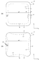
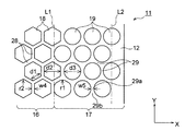
まず、本実施の形態による液体充填ノズル用多孔板の構成について説明する。図1〜図4は、本実施の形態による液体充填ノズル用多孔板の一例を示す図である。このうち図1(a)(b)は、それぞれ本実施の形態による液体充填ノズル用多孔板11の全体平面図であり、図2は、図1に示す液体充填ノズル用多孔板11の部分拡大平面図である。図3は、図1に示す液体充填ノズル用多孔板11のIII−III線における部分拡大断面図であり、図4は、変形例による液体充填ノズル用多孔板11の部分拡大平面図である。
First, the structure of the porous plate for liquid filling nozzles according to the present embodiment will be described. 1-4 is a figure which shows an example of the porous board for liquid filling nozzles by this Embodiment. 1 (a) and 1 (b) are plan views of the entire
図1〜図3に示すように、液体充填ノズル用多孔板11(以下、多孔板11ともいう)は、メッシュ状かつ平板状の金属基板12を備えている。
As shown in FIGS. 1 to 3, the
図1(a)に示すように、金属基板12は、略矩形形状であり、より具体的には角部が丸い正方形形状である。金属基板12の外形をなす直交する2辺は、それぞれ図1(a)のX方向とY方向とに沿って延びている。
As shown in FIG. 1A, the
金属基板12には、略全域にわたり多数の貫通孔18、19(図2参照)が配置されている。金属基板12の平面方向中央側には、開口率の高い第1貫通孔領域16が形成され、金属基板12の平面方向周縁側には、開口率の低い第2貫通孔領域17が形成されている。ここで開口率とは、第1貫通孔領域16(第2貫通孔領域17)全体に占める開口部分(貫通孔18、19)の面積をいう。
In the
第1貫通孔領域16には、その全体にわたり複数の第1貫通孔18(図2参照)が規則的に配列されている。また、第2貫通孔領域17には、複数の第2貫通孔19(図2参照)が規則的に配列されている。なお、第1貫通孔領域16と第2貫通孔領域17との間の境界L1は、第2貫通孔領域17のうち、最も内側に位置する第2貫通孔19を連続的に結んだものである(図2参照)。
In the first through-
図1(a)において、第2貫通孔領域17の幅w2は、金属基板12の外周に沿って略同一となっている。第2貫通孔領域17は、金属基板12の辺から金属基板12の幅w1の10%以上30%以下の領域に設けられることが好ましい(0.1w1≦w2≦0.3w1)。一般に、金属基板12の外周には応力が集中しやすい傾向がある。このため、第2貫通孔領域17を、金属基板12の外周部分の上記範囲に設けることにより、多孔板11の開口率を維持しつつ、多孔板11内の応力集中しやすい箇所の強度を重点的に高めることができる。
In FIG. 1A, the width w <b> 2 of the second through
図1(b)は、変形例による多孔板11を示している。図1(b)において、第2貫通孔領域17は、金属基板12の辺の中心部近傍で最も広く、金属基板12の辺の端部に向かうにつれて徐々に狭くなっている。この場合、金属基板12の辺の中心における第2貫通孔領域17の幅w3は、金属基板12の幅w1の10%以上30%以下の領域とすることが好ましい(0.1w1≦w3≦0.3w1)。上述したように、金属基板12の外周には応力が集中しやすく、更に金属基板12の辺の中心にいくにつれて、より応力が集中しやすい傾向がある。このため、第2貫通孔領域17は、金属基板12の辺の中心部でより幅を広くしている。具体的には、第2貫通孔領域17は、金属基板12の全てが第1貫通孔領域16であると仮定した場合に最大応力が加わる箇所(点P1に対応する箇所)の応力値の50%以上となる範囲に設けることが好ましい。これにより、多孔板11内における応力集中箇所の強度をより効果的に高めることができる。
FIG. 1B shows a
次に、図2を参照して第1貫通孔18および第2貫通孔19の構成について説明する。
Next, the configuration of the first through
図2に示すように、各第1貫通孔18の形状は、正六角形形状であり、互いにほぼ同一の大きさを有している。複数の第1貫通孔18は、いわゆるハニカム状に配置されている。すなわち、1つの第1貫通孔18の周囲には、第1貫通孔18の各辺に隣接して6個の第1貫通孔18が配置されている。第1貫通孔18をハニカム状に配置したことにより、第1貫通孔領域16の開口率を高く維持しつつ、第1貫通孔領域16全体の強度を高めることができる。
As shown in FIG. 2, the shape of each first through-
互いに隣接する第1貫通孔18同士の間には、直線状の第1メッシュ線28が形成されている。この第1メッシュ線28の幅w4は、第1貫通孔18の各辺の長さd1の10%以上50%以下とすることが好ましい。第1メッシュ線28の幅w4は、充填対象とする液体の粘度、充填速度等を考慮して適宜設定することができ、例えば、0.1mm以上0.5mm以下、好ましくは、0.15mm以上0.3mm以下である。第1メッシュ線28の幅w4を上記範囲とすることにより、多孔板11の開口率を維持しつつ、多孔板11内の強度を高めることができる。なお、第1貫通孔18の形状は、正六角形のほか、正方形や正三角形等の多角形形状としても良い。
A linear
各第2貫通孔19の形状は、角部が丸められた正六角形形状であり、互いにほぼ同一の大きさを有している。第2貫通孔19の形状は、第1貫通孔18を構成する正六角形の6つの角部を互いに均一に丸めた形状からなる。第2貫通孔19の対向する辺同士の距離d3は、第1貫通孔18の対向する辺同士の距離d2と互いに同一である。また、距離d2、d3は、充填対象とする液体の粘度、充填速度等を考慮して適宜設定することができ、例えば、0.3mm以上2.5mm以下、好ましくは、0.5mm以上1.5mm以下である。
The shape of each second through
複数の第2貫通孔19は、ハニカム状に配置されている。すなわち、1つの第2貫通孔19の周囲には、第2貫通孔19の各辺に隣接して6個の第2貫通孔19が配置されている。これにより第2貫通孔領域17の開口率を高く維持しつつ、第2貫通孔領域17の強度を高めることができる。
The plurality of second through
互いに隣接する第2貫通孔19同士の間には、第2メッシュ線29が形成されている。この第2メッシュ線29の幅は、その長手方向中心部29a(幅w5)で最も狭く、長手方向端部29bに向けて徐々に広くなっている。第2メッシュ線29の長手方向中心部29aの幅w5は、第1メッシュ線28の幅w4と互いに略同一である。
A
第2貫通孔19の角部の曲率半径r1は、第1貫通孔18を構成する多角形の辺の長さd1の20%以上とすることが好ましい(0.2d1≦r1)。これにより、長手方向端部29bにおける第2メッシュ線29の幅を太くすることができ、第2貫通孔領域17の強度を高めることができる。なお、第1貫通孔18の角部も同様に丸められていても良く、この場合、第2貫通孔19の角部の曲率半径r1は、第1貫通孔18の角部の曲率半径r2よりも大きい。
The radius of curvature r1 of the corner of the second through
第1貫通孔18の形状が、正方形や正三角形等の多角形形状である場合、第2貫通孔19の形状は、当該正方形や正三角形等の角部を丸めた形状からなる。第1貫通孔18同士の配置および第2貫通孔19同士の配置は、ハニカム状に限らず、格子状、千鳥状等のパターンとしてもよい。
When the shape of the 1st through-
なお、図2において、直線L2は、後述する環状スペーサ21の内周縁の位置を示している(図7参照)。
In addition, in FIG. 2, the straight line L2 has shown the position of the inner periphery of the cyclic |
図3の断面図に示すように、第1貫通孔18および第2貫通孔19は、それぞれ金属基板12を厚み方向(金属基板12の平面に直交する方向、Z方向)に貫通している。また、第1貫通孔18および第2貫通孔19は、それぞれ金属基板12を両面からエッチングすることにより形成される。このため、金属基板12の内壁には、第1貫通孔18および第2貫通孔19の中心に向かって周状に突出する凸部Tが形成されている。これにより、液体の充填停止時に多孔板11によって液体をより効果的に保持することができる。
As shown in the cross-sectional view of FIG. 3, the first through
このように、金属基板12の中央側に、開口率の高い第1貫通孔領域16を配置し、金属基板12の周縁側に、第1貫通孔領域16よりも開口率の低い第2貫通孔領域17を配置している。これにより、第2貫通孔領域17の強度を相対的に高め、多孔板11内において応力集中しやすい箇所の強度を高めることができる。一方、第1貫通孔領域16の開口率が相対的に高く維持されているので、液体を充填する際に充填の生産性が大きく低下することはない。
As described above, the first through-
図4は、多孔板11の変形例を示している。図4において、図1〜図3に示す形態と異なり、各第2貫通孔19の形状は円形状となっている。この場合、長手方向端部29bにおける第2メッシュ線29の幅をより太くすることができるので、第2貫通孔領域17の強度を更に高めることができる。なお、円形状からなる第2貫通孔19の直径d3は、第1貫通孔18の対向する辺同士の距離d2と互いに同一である。
FIG. 4 shows a modification of the
B.液体充填ノズル用積層板
次に、本実施の形態による液体充填ノズル用積層板の構成について説明する。図5および図6は、本実施の形態による液体充填ノズル用積層板の一例を示す説明図である。図5は、本実施の形態による液体充填ノズル用積層板10の全体平面図であり、図6は、図5に示す液体充填ノズル用積層板10のVI−VI線における部分拡大断面図である。
B. Liquid filling nozzles laminates Next, the configuration of the liquid filling nozzle laminates according to the present embodiment. 5 and 6 are explanatory views showing an example of a liquid-filled nozzle laminate according to the present embodiment. FIG. 5 is an overall plan view of the liquid-filled
図5および図6に示すように、液体充填ノズル用積層板10は、上述した多孔板11と、多孔板11に積層された環状スペーサ21とを備えている。このうち環状スペーサ21は、枠体22と、枠体22によって取り囲まれた開口部23とからなる。液体充填ノズル用積層板10において、多孔板11の周縁に位置する第2貫通孔19は、環状スペーサ21の枠体22と重なる領域にも形成されている。
As shown in FIGS. 5 and 6, the liquid-filled
図5に示すように、環状スペーサ21は、角部が丸い正方形であり、これらの外形をなす直交する2辺は、図5のX方向とY方向とに沿って延びている。多孔板11と環状スペーサ21とは、ほぼ同一の大きさを有し、それぞれの外形が一致するよう積層されている。一方、多孔板11の第2貫通孔領域17は、環状スペーサ21によって覆われる領域と、環状スペーサ21よりも内側に位置する領域とに分離されている。
As shown in FIG. 5, the
図6の断面図に示すように、本実施の形態において、多孔板11を2枚、貫通孔18、19が重なるように積層しているため、凸部Tは連結された各貫通孔18、19の内側に2ヶ所設けられている。
As shown in the cross-sectional view of FIG. 6, in the present embodiment, since the two
図7(a)および図7(b)は、それぞれ図5に示す液体充填ノズル用積層板10のVIIA部の部分拡大平面図と、VIIA部を液体充填ノズル用積層板10の外側(図5(a)のVIIB方向)から見た側面図である。図7(a)において、網掛けで示す領域は、多孔板11と環状スペーサ21の枠体22とが平面視で重なる領域である。L2は、環状スペーサ21の内周縁の位置を示す。また、枠体22(環状スペーサ21)の外形L3の外側には第2貫通孔19のパターンは存在しないが、説明のために図示している。
FIG. 7A and FIG. 7B are respectively a partially enlarged plan view of the VIIA part of the liquid-filled
貫通孔18、19のパターンは、多孔板11のうち、環状スペーサ21の枠体22と重なる領域(以下、枠体領域14という)と、環状スペーサ21の開口部23と重なる領域(以下、開口領域15という)とに、一様に形成されている。この場合、第2貫通孔19が多孔板11の枠体領域14にも形成され、多孔板11と環状スペーサ21とを積層した際に、第2貫通孔19が枠体22と重なるよう構成されている。そのため、従来の貫通孔が枠体領域14に形成されない場合のように、開口領域15の外縁部に位置する貫通孔18、19を枠体22の形状に沿って形成する必要がない。したがって、多孔板11をエッチングにより作製しても、これらの貫通孔18、19が設計よりも小さく形成されたり、貫通しなかったりすることがなく、流れ抵抗の小さな液体充填ノズル用積層板とすることができる。
The patterns of the through
本実施の形態による多孔板11の金属基板12の材質としては、例えば、オーステナイト系、フェライト系、マルテンサイト系のステンレス鋼、チタン、チタン合金、ニッケル、ニッケル合金等が挙げられる。
Examples of the material of the
また、環状スペーサ21の材質としては、オーステナイト系、フェライト系、マルテンサイト系のステンレス鋼、チタン、チタン合金、ニッケル、ニッケル合金等が挙げられる。
Examples of the material of the
多孔板11の厚みは、例えば、0.1mm以上1.0mm以下、好ましくは、0.2mm以上0.6mm以下である。また、環状スペーサ21の厚みは、例えば、0.1mm以上1.0mm以下、好ましくは、0.3mm以上0.6mm以下である。
The thickness of the
多孔板11および環状スペーサ21の大きさは、使用する液体充填ノズルの形状に応じて、例えば、一辺の長さが30mm以上80mm以下とすることができ、形状は、正方形に限定されず、使用する液体充填ノズルの形状に応じて、他の矩形、多角形、円形、楕円形等であってもよい。
The size of the
図5および図6においては、多孔板11が2枚積層され、さらにこの上下に環状スペーサ21が1枚ずつ積層されているが、本実施の形態の液体充填ノズル用積層板10はこれに限定されず、環状スペーサ21は、1枚あるいは3枚以上の多孔板11の上下に積層されていてもよく、また、多孔板11の上側あるいは下側の一方にのみ積層されていてもよく、さらに多孔板11の間に積層されていてもよい。
5 and 6, two
次に、多孔板11と環状スペーサ21の枠体22とが重なる部分について説明する。図7(a)に示すように、液体充填ノズル用積層板10は、環状スペーサ21の枠体22の幅に、多孔板11の第2貫通孔19が入るように構成されている。すなわち、枠体22の幅w6は、第2貫通孔19の対向する辺同士の距離d3よりも大きく、多孔板11と環状スペーサ21とは、枠体22の幅に第2貫通孔19が入るよう積層されている。
Next, a portion where the
このように、本実施の形態による液体充填ノズル用積層板10は、環状スペーサ21の枠体22の幅に、多孔板11の第2貫通孔19が入るよう構成されているため、多孔板11の第2貫通孔19の周囲の金属基板12を環状スペーサ21の枠体22に接合させることができる。したがって、多孔板11と環状スペーサ21の接合強度を大きくすることができ、より耐久性に優れた液体充填ノズル用積層板とすることができる。なお、枠体が矩形状の場合には、各辺でそれぞれ貫通孔が少なくとも1つ以上含まれるように形成することが強度の点で好ましい。
Thus, since the
環状スペーサ21の枠体22の幅w6は、使用する液体充填ノズル60(図9参照)の形状に応じて、例えば、0.6mm以上3.0mm以下とすることができる。
The width w6 of the
C.液体充填ノズル用積層板の製造方法
次に、本実施の形態に係る液体充填ノズル用積層板の製造方法について説明する。
C. Method for Producing Liquid Filled Nozzle Laminate Next, a method for producing a liquid filled nozzle laminate according to this embodiment will be described.
本実施の形態においては、平面内に多孔板11が複数設けられた多孔板シート30と、平面内に環状スペーサ21が複数設けられた環状スペーサシート40とを積層し、この積層体を、多孔板11および環状スペーサ21ごとに個片化して、液体充填ノズル用積層板10を作製する。
In the present embodiment, a
すなわち、まず、図8(a)に示すように、平板状の金属基板シート10Aを準備する。この金属基板シート10Aは、後述のように、平板状の金属基材に、環状スペーサ21の開口部23が複数設けられた環状スペーサシート40と接合し、その後、開口部23ごとに切断することにより、複数の液体充填ノズル用積層板10を多面付けして作製することが可能な大きさを有している。この金属基板シート10Aの材質は、上述の金属基板12と同じである。
That is, first, as shown in FIG. 8A, a flat
次に、図8(b)に示すように、金属基板シート10Aに複数の第1貫通孔18および複数の第2貫通孔19を形成し、多孔板シート30を作製する。多孔板シート30は多孔板11の多面付け体であり、第1貫通孔18および第2貫通孔19は、多孔板シート30の外周を除く全面に形成されている。この場合、第1貫通孔18は、各多孔板11の中央に対応する領域(第1貫通孔領域16)に形成され、第2貫通孔19は、各多孔板11の周縁に対応する領域(第2貫通孔領域17)に形成される。
Next, as shown in FIG. 8B, a plurality of first through
第1貫通孔18および第2貫通孔19は、金属基板シート10Aに対して、表裏からウエットエッチングまたはドライエッチングを施すことにより形成される。この際のエッチング液は、使用する金属基板シート10Aの材質に応じて適宜選択することができ、例えば、金属基板シート10Aとしてステンレス鋼を用いる場合、通常、塩化第二鉄水溶液を使用し、スプレーエッチングにて行うことができる。
The first through
図8(b)に示すように、多孔板シート30の外周には、多孔板シート30および環状スペーサ21を積層する際に用いる位置合わせ用孔部33が形成されていてもよい。ここで、位置合わせ用孔部33は、多孔板シート30の4隅と外周の4辺とに複数設けられている。
As shown in FIG. 8B, an
次に、図8(c)に模式的に示すように、多孔板シート30を2枚積層し、接合する。この接合は、焼結接合、拡散接合、アーク溶接、抵抗溶接、ロウ付け等により行うことができる。
Next, as schematically shown in FIG. 8C, two
続いて、図8(d)に示すように、環状スペーサ21の多面付け体である環状スペーサシート40を準備し、多孔板シート30の表面および裏面に積層しかつ接合することにより、液体充填ノズル用積層板シート50を得る。環状スペーサシート40は、平面内に環状スペーサ21が複数設けられた環状スペーサ21の多面付け体であり、枠体連結部41に環状スペーサ21の開口部23が複数設けられている。また、多孔板シート30に位置合わせ用孔部33が形成されている場合には、環状スペーサシート40にも、多孔板シート30と積層した際に重なる位置に位置合わせ用孔部33が形成される。
Subsequently, as shown in FIG. 8 (d), an
多孔板シート30と環状スペーサシート40との接合は、上述の多孔板シート30同士の接合と、同様の方法により行うことができる。ここで焼結接合や拡散接合のように高温雰囲気下で長時間かけて接合する工程では、熱変形(特に伸びる変形)が発生しやすい。そこで位置合わせ用孔部33を各辺の中央付近に長円形状で設けるか、もしくは環状スペーサシート40の位置合わせ用孔部33よりも多孔板シート30の位置合わせ用孔部33の方が大きくなるよう形成することで熱変形の影響を抑えて積層することができる。
The
次に、図8(e)に示すように、このようにして作製された多孔板シート30と環状スペーサシート40の積層体を、ワイヤー放電カット等により、環状スペーサシート40の開口部23ごとに切断する。開口部23は、それぞれ環状スペーサ21に対応するため、これにより、多孔板シート30と環状スペーサシート40との積層体を、環状スペーサ21ごとに個片化することができる。このようにして、図5〜図7に示す液体充填ノズル用積層板10を得ることができる。なお、図8(c)、(d)、(e)においては、積層体の層構成が分かり易いよう多孔板11と環状スペーサ21とを分けて図示しているが、実際はこれらは互いに接合されている。
Next, as shown in FIG.8 (e), the laminated body of the porous plate sheet |
本実施の形態による液体充填ノズル用積層板10は、上述のように作製されるため、多孔板11の第2貫通孔19を、環状スペーサ21の枠体22と重なる領域にも形成することができる。そのため、従来の貫通孔が枠体22と重なる領域に形成されない場合のように、多孔板11の開口領域15端部の貫通孔を、枠体22の形状に沿って形成する必要がなく、耐久性に優れ、流れ抵抗の小さな液体充填ノズル用積層板10とすることができる。
Since the liquid-filled
また、第2貫通孔19を、多孔板11の開口領域15の端部まで設けることができるため、開口率が高く、流れ抵抗が小さな液体充填ノズル用積層板10を得ることができる。
Moreover, since the 2nd through-
図8(c)、(d)においては、2枚の多孔板シート30を積層し、さらにこの表裏に環状スペーサ21を積層する場合を示したが、本実施の形態の液体充填ノズル用積層板の製造方法はこれに限定されない。環状スペーサ21は、1枚あるいは3枚以上の多孔板シート30の表裏に積層してもよく、また、多孔板シート30の積層体の表側または裏側の一方にのみ積層してもよく、さらに多孔板シート30同士の間に積層してもよい。また、液体充填ノズル用積層板10を製造する場合、上記に限らず、多孔板11と環状スペーサ21とを個々に作製し、互いに積層するようにしても良い。
8 (c) and 8 (d) show a case where two
D.液体充填ノズル
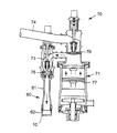
次に、本実施の形態による液体充填ノズル用積層板10を有する液体充填ノズル60の一実施形態について説明する。図9は、液体充填ノズル60および液体充填装置70の一例を示す説明図である。
D. Liquid Filling Nozzle Next, an embodiment of the
図9に示すように、液体充填ノズル60は、筒状ノズル本体61と、筒状ノズル本体61の先端に設けられた吐出口62を有している。本実施の形態による液体充填ノズル用積層板10は、固定部材により、液体充填ノズル60の吐出口62近傍、特に吐出側先端に装着される。
As shown in FIG. 9, the
E.液体充填装置
次に、本実施の形態による液体充填ノズル用積層板10を有する液体充填装置70の一実施形態について説明する。本実施の形態による液体充填装置70は、液体充填ノズル60と、定量シリンダ71と、図示しないタンクとを備えている。液体充填ノズル60と定量シリンダ71とは接続配管73により接続され、また定量シリンダ71とタンクとは、供給管74により接続されている。接続配管73と供給管74とには、それぞれ流出逆止弁75と流入逆止弁76とが設けられている。
E. Liquid filling apparatus will now be described an embodiment of a
定量シリンダ71の内部には、ピストン77が上下動可能に設けられている。ピストン77を下方へ移動させると、流入逆止弁76が開き、タンクの液体が、供給管74を通って定量シリンダ71へと供給される。また、ピストン77を上方へ移動させると、流出逆止弁75が開き、定量シリンダ71へ供給された液体が、接続配管73を通って液体充填ノズル60に送り込まれ、図示しない容器へと充填される。
A
また、本実施の形態による液体充填装置により液体が充填される対象となる容器の形状、材質には特に制限はなく、例えば、種々の形状の紙製容器、樹脂製容器、ガラス製容器、金属製容器等を用いることができる。 Moreover, there is no restriction | limiting in particular in the shape and material of the container used as the object filled with the liquid by the liquid filling apparatus by this Embodiment, For example, paper containers of various shapes, resin containers, glass containers, metal A container or the like can be used.
このような液体充填装置70を使用する際、液体充填ノズル用積層板10によって液体が整流され、図示しない容器へ送り込まれる。この際、液体充填ノズル用積層板10の多孔板11には、高圧の液体によって繰り返し圧力が加わり、多孔板11のうち、とりわけ周縁部に応力が集中する。
When such a
これに対して本実施の形態によれば、多孔板11の金属基板12の中央側に、複数の第1貫通孔18が規則的に配列され、金属基板12の周縁側には、複数の第2貫通孔19が規則的に配列されている。この場合、各第1貫通孔18の形状は、多角形形状であり、各第2貫通孔19の形状は、第1貫通孔18を構成する多角形の角部を丸めた形状であるか、又は円形状となっている。このように、多孔板11のうち、応力が集中しやすい箇所である周縁部の強度を確保しつつ、多孔板11全体としての開口率を高く維持している。これにより、液体充填装置70を長期間使用した後であっても、多孔板11に変形や損傷が生じることを防止することができる。また、多孔板11の開口率が大きく低下することがないので、液体充填装置70による充填の生産性が低下するおそれもない。
On the other hand, according to the present embodiment, a plurality of first through
上記実施の形態に開示されている複数の構成要素を必要に応じて適宜組合せることも可能である。あるいは、上記実施の形態に示される全構成要素から幾つかの構成要素を削除してもよい。 A plurality of constituent elements disclosed in the above-described embodiment can be appropriately combined as necessary. Or you may delete a some component from all the components shown by the said embodiment.
10 液体充填ノズル用積層板
11 液体充填ノズル用多孔板
12 金属基板
16 第1貫通孔領域
17 第2貫通孔領域
18 第1貫通孔
19 第2貫通孔
21 環状スペーサ
22 枠体
23 開口部
28 第1メッシュ線
29 第2メッシュ線
70 液体充填装置
DESCRIPTION OF
Claims (7)
平板状の金属基板を備え、
前記金属基板の中央側には、複数の第1貫通孔が規則的に配列され、
前記金属基板の周縁側には、複数の第2貫通孔が規則的に配列され、
各第1貫通孔の形状は、多角形形状であり、
各第2貫通孔の形状は、前記第1貫通孔を構成する多角形の角部を丸めた形状であるか、又は円形状であることを特徴とする液体充填ノズル用多孔板。 A perforated plate for a liquid filling nozzle,
It has a flat metal substrate,
A plurality of first through holes are regularly arranged on the center side of the metal substrate,
A plurality of second through holes are regularly arranged on the peripheral side of the metal substrate,
The shape of each first through hole is a polygonal shape,
The shape of each second through-hole is a shape obtained by rounding the corners of the polygon that constitutes the first through-hole, or a circular shape.
前記液体充填ノズル用多孔板に積層され、枠体と開口部とを有する環状スペーサとを備えたことを特徴とする液体充填ノズル用積層板。 A perforated plate for a liquid filling nozzle according to any one of claims 1 to 5,
A laminated plate for a liquid filling nozzle, comprising: an annular spacer having a frame and an opening laminated on the porous plate for a liquid filling nozzle.
前記液体充填ノズルは、筒状ノズル本体と、筒状ノズル本体の先端に設けられた吐出口を有し、前記吐出口近傍には、請求項6に記載の液体充填ノズル用積層板が装着されていることを特徴とする液体充填装置。 A liquid filling apparatus having a liquid filling nozzle, a metering cylinder, and a connection pipe connecting the liquid filling nozzle and the metering cylinder,
The liquid filling nozzle has a cylindrical nozzle body and a discharge port provided at a tip of the cylindrical nozzle body, and the laminated plate for a liquid filling nozzle according to claim 6 is mounted in the vicinity of the discharge port. A liquid filling apparatus characterized by comprising:
Priority Applications (1)
| Application Number | Priority Date | Filing Date | Title |
|---|---|---|---|
| JP2016098077A JP6786868B2 (en) | 2016-05-16 | 2016-05-16 | Perforated plate for liquid filling nozzle, laminated plate for liquid filling nozzle and liquid filling device |
Applications Claiming Priority (1)
| Application Number | Priority Date | Filing Date | Title |
|---|---|---|---|
| JP2016098077A JP6786868B2 (en) | 2016-05-16 | 2016-05-16 | Perforated plate for liquid filling nozzle, laminated plate for liquid filling nozzle and liquid filling device |
Publications (2)
| Publication Number | Publication Date |
|---|---|
| JP2017206267A true JP2017206267A (en) | 2017-11-24 |
| JP6786868B2 JP6786868B2 (en) | 2020-11-18 |
Family
ID=60416198
Family Applications (1)
| Application Number | Title | Priority Date | Filing Date |
|---|---|---|---|
| JP2016098077A Expired - Fee Related JP6786868B2 (en) | 2016-05-16 | 2016-05-16 | Perforated plate for liquid filling nozzle, laminated plate for liquid filling nozzle and liquid filling device |
Country Status (1)
| Country | Link |
|---|---|
| JP (1) | JP6786868B2 (en) |
Cited By (1)
| Publication number | Priority date | Publication date | Assignee | Title |
|---|---|---|---|---|
| CN116238741A (en) * | 2023-04-28 | 2023-06-09 | 帕克奇科技(杭州)有限公司 | Intelligent injector filling system and working method |
Citations (5)
| Publication number | Priority date | Publication date | Assignee | Title |
|---|---|---|---|---|
| JPH0999914A (en) * | 1995-10-05 | 1997-04-15 | Shikoku Kakoki Co Ltd | Filling nozzle |
| JP2005280810A (en) * | 2004-03-30 | 2005-10-13 | Mitsubishi Heavy Ind Ltd | Liquid-filling nozzle and liquid-filling device |
| JP2008536680A (en) * | 2005-04-19 | 2008-09-11 | エバーグリーン・パッケージング・インターナショナル・ベスローテン・フエンノートシャップ | Fluid discharge nozzle |
| JP2013094721A (en) * | 2011-10-31 | 2013-05-20 | Sumitomo Chemical Co Ltd | Honeycomb structure |
| JP2015160626A (en) * | 2014-02-27 | 2015-09-07 | 大日本印刷株式会社 | Porous plate for liquid filling nozzle and liquid filling device |
-
2016
- 2016-05-16 JP JP2016098077A patent/JP6786868B2/en not_active Expired - Fee Related
Patent Citations (5)
| Publication number | Priority date | Publication date | Assignee | Title |
|---|---|---|---|---|
| JPH0999914A (en) * | 1995-10-05 | 1997-04-15 | Shikoku Kakoki Co Ltd | Filling nozzle |
| JP2005280810A (en) * | 2004-03-30 | 2005-10-13 | Mitsubishi Heavy Ind Ltd | Liquid-filling nozzle and liquid-filling device |
| JP2008536680A (en) * | 2005-04-19 | 2008-09-11 | エバーグリーン・パッケージング・インターナショナル・ベスローテン・フエンノートシャップ | Fluid discharge nozzle |
| JP2013094721A (en) * | 2011-10-31 | 2013-05-20 | Sumitomo Chemical Co Ltd | Honeycomb structure |
| JP2015160626A (en) * | 2014-02-27 | 2015-09-07 | 大日本印刷株式会社 | Porous plate for liquid filling nozzle and liquid filling device |
Cited By (2)
| Publication number | Priority date | Publication date | Assignee | Title |
|---|---|---|---|---|
| CN116238741A (en) * | 2023-04-28 | 2023-06-09 | 帕克奇科技(杭州)有限公司 | Intelligent injector filling system and working method |
| CN116238741B (en) * | 2023-04-28 | 2023-08-04 | 帕克奇科技(杭州)有限公司 | Intelligent injector filling system and working method |
Also Published As
| Publication number | Publication date |
|---|---|
| JP6786868B2 (en) | 2020-11-18 |
Similar Documents
| Publication | Publication Date | Title |
|---|---|---|
| US8793877B2 (en) | Apparatus for manufacturing truss structure using multi-point pins, method of manufacturing truss structure using the same, truss core sandwich panel having the truss structure, method of manufacturing the truss core sandwich panel | |
| KR101207472B1 (en) | Sandwich plate with sandwich-core using pyramidal truss-structure, and its manufacturing method | |
| EP2456618B1 (en) | Formed core sandwich structures | |
| US11879798B2 (en) | Perforated support layer that facilitates static and dynamic bending | |
| JP2011174689A (en) | Method of manufacturing plate type heat exchanger and the plate type heat exchanger | |
| KR102438952B1 (en) | Folding plate and its manufacturing method | |
| KR20190045725A (en) | Composite panel for sound absoption and sound insulation | |
| EP3034226A1 (en) | Method for manufacturing a sandwich panel | |
| JP2017206267A (en) | Perforated plate for liquid charging nozzle, laminated sheet for liquid charging nozzle, and liquid charging device | |
| JP2017206268A (en) | Perforated plate for liquid charging nozzle, laminated sheet for liquid charging nozzle, and liquid charging device | |
| JP6471458B2 (en) | Laminated plate for liquid filling nozzle, method for producing the same, and liquid filling device | |
| US8555501B2 (en) | Method of manufacturing a blade | |
| US20140170374A1 (en) | Core of Sheet Structural Material and Assembly Process | |
| JP5941846B2 (en) | Plate material having concavo-convex part, vehicle panel and laminated structure using the same | |
| JP2006137029A (en) | Panel structural material | |
| JP2016084146A (en) | Laminated plate for liquid filling nozzle, method for producing the same, and liquid filling device | |
| KR101530880B1 (en) | A Sandwich plate comprising truss-structure and A manufacturing method of the same | |
| CN103551444B (en) | Manufacture the method for hollow structure | |
| JPWO2012098787A1 (en) | Plate material having concavo-convex part, vehicle panel and laminated structure using the same | |
| JP6079410B2 (en) | Plate heat exchanger | |
| JP2014126258A (en) | Heat exchanger | |
| JP2012154594A (en) | Plate heat exchanger and method for manufacturing the same | |
| JP6085878B2 (en) | Metal plate processing method and metal net | |
| CN104139277A (en) | Manufacturing method of small-sized hollow closed part | |
| JP6650679B2 (en) | Vaporizing humidifier |
Legal Events
| Date | Code | Title | Description |
|---|---|---|---|
| A621 | Written request for application examination |
Free format text: JAPANESE INTERMEDIATE CODE: A621 Effective date: 20190327 |
|
| A977 | Report on retrieval |
Free format text: JAPANESE INTERMEDIATE CODE: A971007 Effective date: 20200114 |
|
| A131 | Notification of reasons for refusal |
Free format text: JAPANESE INTERMEDIATE CODE: A131 Effective date: 20200218 |
|
| A521 | Request for written amendment filed |
Free format text: JAPANESE INTERMEDIATE CODE: A523 Effective date: 20200420 |
|
| TRDD | Decision of grant or rejection written | ||
| A01 | Written decision to grant a patent or to grant a registration (utility model) |
Free format text: JAPANESE INTERMEDIATE CODE: A01 Effective date: 20200929 |
|
| A61 | First payment of annual fees (during grant procedure) |
Free format text: JAPANESE INTERMEDIATE CODE: A61 Effective date: 20201012 |
|
| R150 | Certificate of patent or registration of utility model |
Ref document number: 6786868 Country of ref document: JP Free format text: JAPANESE INTERMEDIATE CODE: R150 |
|
| LAPS | Cancellation because of no payment of annual fees |