JP2017206331A - Sheet discharge device and image formation apparatus having the same - Google Patents
Sheet discharge device and image formation apparatus having the same Download PDFInfo
- Publication number
- JP2017206331A JP2017206331A JP2016098391A JP2016098391A JP2017206331A JP 2017206331 A JP2017206331 A JP 2017206331A JP 2016098391 A JP2016098391 A JP 2016098391A JP 2016098391 A JP2016098391 A JP 2016098391A JP 2017206331 A JP2017206331 A JP 2017206331A
- Authority
- JP
- Japan
- Prior art keywords
- sheet
- discharge
- width direction
- paper
- roller pair
- Prior art date
- Legal status (The legal status is an assumption and is not a legal conclusion. Google has not performed a legal analysis and makes no representation as to the accuracy of the status listed.)
- Pending
Links
Images


Landscapes
- Feeding Of Articles By Means Other Than Belts Or Rollers (AREA)
- Separation, Sorting, Adjustment, Or Bending Of Sheets To Be Conveyed (AREA)
Abstract
【課題】シートの幅方向端部に生じる上向きのカールを効果的に矯正可能なシート排出装置及びそれを備えた画像形成装置を提供する。
【解決手段】シート排出装置は、シート排出口と、搬送ガイドと、排出ローラー対と、カール矯正部材と、を備える。搬送ガイドは、シート排出口にシートを案内する。排出ローラー対は、シート排出口の近傍に複数設けられる。カール矯正部材は、複数の排出ローラー対のうちシート幅方向の最も外側に配置された排出ローラー対から排出ローラー対を通過するシートの幅方向両端縁までの間に配置され、シートを上方から押圧して上向きのカールを矯正する。カール矯正部材は、排出ローラー対のニップ部よりも下方まで略垂直に突出してシートの上面に接触する板状の押圧片を有する。押圧片は、シート排出方向の上流側から下流側に向かってシート幅方向の外側に傾斜するように配置されている。
【選択図】図4A sheet discharge device and an image forming apparatus including the sheet discharge device capable of effectively correcting upward curling generated at the end portion in the width direction of the sheet are provided.
A sheet discharge device includes a sheet discharge port, a conveyance guide, a discharge roller pair, and a curl correction member. The conveyance guide guides the sheet to the sheet discharge port. A plurality of discharge roller pairs are provided in the vicinity of the sheet discharge port. The curl correction member is arranged between the discharge roller pair arranged on the outermost side in the sheet width direction from the plurality of discharge roller pairs to both edges in the width direction of the sheet passing through the discharge roller pair, and presses the sheet from above. And correct the upward curl. The curl correction member has a plate-like pressing piece that protrudes substantially perpendicularly below the nip portion of the discharge roller pair and contacts the upper surface of the sheet. The pressing piece is disposed so as to be inclined outward in the sheet width direction from the upstream side in the sheet discharge direction toward the downstream side.
[Selection] Figure 4
Description
本発明は、複写機、プリンター、ファクシミリ等の画像形成装置に用いられる、シート状の用紙や原稿を排出するシート排出装置及びそれを備えた画像形成装置に関するものである。 The present invention relates to a sheet discharging apparatus that discharges sheet-like paper or a document used in an image forming apparatus such as a copying machine, a printer, and a facsimile machine, and an image forming apparatus including the sheet discharging apparatus.
電子写真方式を用いた画像形成装置では、感光体ドラム等の像担持体上に形成した静電潜像にトナーを付与してトナー像を形成し、トナー像を用紙等のシート状の記録媒体に転写した後、定着装置(定着部)によって用紙上のトナー像を定着させている。 In an image forming apparatus using an electrophotographic system, a toner image is formed by applying toner to an electrostatic latent image formed on an image carrier such as a photosensitive drum, and the toner image is formed into a sheet-like recording medium such as paper. Then, the toner image on the paper is fixed by a fixing device (fixing unit).
このような画像形成装置においては、定着装置によって加熱、加圧された用紙は、条件によっては大きくカール(巻きぐせ)を生じることがある。このように用紙が局所的にカールすると、用紙排出口を塞ぎ、排出トレイ上へ排出される用紙の整列性や積載性を著しく損なう上、先に積載されていた用紙が排出方向に押し出されて排出トレイから落下するおそれもあった。 In such an image forming apparatus, the paper heated and pressed by the fixing device may be largely curled (rolled) depending on conditions. When the paper is curled locally in this way, the paper discharge port is blocked, and the alignment and stackability of the paper discharged onto the discharge tray are significantly impaired, and the previously loaded paper is pushed out in the discharge direction. There was also a risk of falling from the discharge tray.
そこで、用紙のカールを矯正する方法が種々提案されており、例えば特許文献1には、排出ローラー対のニップ部からシート搬送方向の上流側に延在しており、シートと接触して押圧することによりシートにコシを付ける腰付け部材を配置したシート搬送装置が開示されている。
Therefore, various methods for correcting the curl of the paper have been proposed. For example,
特許文献1の構成では、複数の排出ローラー対の間に腰付け部材を配置することにより、用紙を幅方向に沿って波打ち形状として用紙にコシを付けるものである。そのため、用紙の幅方向端部に生じた上方向のカールを効果的に矯正できないという問題点があった。
In the configuration of
本発明は、上記問題点に鑑み、シートの幅方向端部に生じる上向きのカールを効果的に矯正可能なシート排出装置及びそれを備えた画像形成装置を提供することを目的とする。 SUMMARY An advantage of some aspects of the invention is that it provides a sheet discharge device that can effectively correct upward curling that occurs at an end portion in the width direction of a sheet, and an image forming apparatus including the sheet discharge device.
上記目的を達成するために本発明の第1の構成は、シート排出口と、搬送ガイドと、排出ローラー対と、カール矯正部材と、を備え、排出トレイ上にシートを順次排出して積載するシート排出装置である。シート排出口は、シートが排出される。搬送ガイドは、シートの上面に対向する上搬送ガイドと、シートの下面に対向する下搬送ガイドとで構成され、シート排出口にシートを案内する。排出ローラー対は、シート排出口の近傍に複数設けられる。カール矯正部材は、複数の排出ローラー対のうちシート幅方向の最も外側に配置された排出ローラー対から排出ローラー対を通過するシートの幅方向両端縁までの間に配置され、シートを上方から押圧して上向きのカールを矯正する。カール矯正部材は、排出ローラー対のニップ部よりも下方まで略垂直に突出してシートの上面に接触する板状の押圧片を有する。押圧片は、シート排出方向の上流側から下流側に向かってシート幅方向の外側に傾斜するように配置されている。 In order to achieve the above object, a first configuration of the present invention includes a sheet discharge port, a conveyance guide, a discharge roller pair, and a curl correction member, and sequentially discharges and stacks sheets on a discharge tray. A sheet discharge device. The sheet is discharged from the sheet discharge port. The conveyance guide includes an upper conveyance guide that faces the upper surface of the sheet and a lower conveyance guide that faces the lower surface of the sheet, and guides the sheet to the sheet discharge port. A plurality of discharge roller pairs are provided in the vicinity of the sheet discharge port. The curl correction member is arranged between the discharge roller pair arranged on the outermost side in the sheet width direction from the plurality of discharge roller pairs to both edges in the width direction of the sheet passing through the discharge roller pair, and presses the sheet from above. And correct the upward curl. The curl correction member has a plate-like pressing piece that protrudes substantially perpendicularly below the nip portion of the discharge roller pair and contacts the upper surface of the sheet. The pressing piece is disposed so as to be inclined outward in the sheet width direction from the upstream side in the sheet discharge direction toward the downstream side.
本発明の第1の構成によれば、シート排出方向に対し上流側から下流側に向かってシート幅方向の外側に傾斜する押圧片により、シートが排出されていくにつれて押圧片の接触位置がシートの幅方向外側に移動する。これにより、シートの幅方向両端部が押圧片によって内側から外側に向かって押し広げられつつ下向きに押圧されるため、シートの幅方向両端部に発生する上カールを効果的に矯正することができる。 According to the first configuration of the present invention, the contact position of the pressing piece is set as the sheet is discharged by the pressing piece that is inclined outward in the sheet width direction from the upstream side to the downstream side with respect to the sheet discharging direction. Move outward in the width direction. As a result, both end portions in the width direction of the sheet are pressed downward while being spread from the inside toward the outside by the pressing pieces, so that it is possible to effectively correct the upper curl generated at both ends in the width direction of the sheet. .
以下、図面を参照しながら本発明の実施形態について説明する。図1は、本発明の一実施形態に係る用紙排出装置30(図2参照)が搭載される画像形成装置100の内部構造を示す側面断面図である。図1に示すように、画像形成装置(例えばモノクロプリンター)100内には、帯電、露光、現像及び転写の各工程によりモノクロ画像を形成する画像形成部Pが配設されている。画像形成部Pには、感光体ドラム5の回転方向(図1の時計回り方向)に沿って、帯電ユニット4、露光ユニット(レーザー走査ユニット等)7、現像ユニット8、転写ローラー14、クリーニング装置19、及び除電装置(図示せず)が配設されている。
Hereinafter, embodiments of the present invention will be described with reference to the drawings. FIG. 1 is a side sectional view showing an internal structure of an
画像形成動作を行う場合、帯電ユニット4により時計回り方向に回転する感光体ドラム5が一様に帯電され、原稿画像データに基づく露光ユニット7からのレーザービームにより感光体ドラム5上に静電潜像が形成され、現像ユニット8により静電潜像に現像剤(以下、トナーという)が付着されてトナー像が形成される。
When the image forming operation is performed, the
この現像ユニット8へのトナーの供給はトナーコンテナ9から行われる。なお、画像データはパーソナルコンピューター(図示せず)等から送信される。また、感光体ドラム5の表面の残留電荷を除去する除電装置(図示せず)がクリーニング装置19の下流側に設けられている。
The toner is supplied to the developing
上記のようにトナー像が形成された感光体ドラム5に向けて、用紙が給紙カセット10から用紙搬送路12及びレジストローラー対13を経由して搬送され、転写ローラー14(画像転写部)により感光体ドラム5の表面に形成されたトナー像が用紙に転写される。トナー像が転写された用紙は感光体ドラム5から分離され、定着装置15に搬送されてトナー像が定着される。
The sheet is conveyed from the
定着装置15及び搬送ローラー対23を通過した用紙は、用紙搬送路16により画像形成装置100の上部に搬送され、用紙の片面のみに画像を形成する場合(片面印字時)は、用紙排出装置30(図2参照)の排出ローラー対17を介して排出トレイ18に排出される。
The paper that has passed through the
一方、用紙の両面に画像を形成する場合(両面印字時)は、用紙の後端が用紙搬送路16の分岐部20を通過した後に排出ローラー対17を逆回転させて搬送方向を反転させる。これにより、用紙は分岐部20から反転搬送路21に振り分けられ、画像面を反転させた状態でレジストローラー対13に再搬送される。そして、感光体ドラム5上に形成された次のトナー像が、転写ローラー14によって用紙の画像が形成されていない面に転写される。トナー像が転写された用紙は、定着装置15に搬送されてトナー像が定着された後、排出ローラー対17を介して排出トレイ18に排出される。
On the other hand, when images are formed on both sides of the paper (during double-sided printing), the
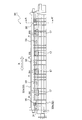
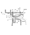
図2は、画像形成装置100に搭載される用紙排出装置30を用紙排出方向下流側(図1の左側)から見た正面図であり、図3は、カール矯正部材35の支持部37を含む用紙排出装置30の側面断面図(図2のAA′矢視断面図)である。用紙排出装置30は、用紙排出口31と、用紙排出口31に用紙を案内する上搬送ガイド32a及び下搬送ガイド32bから成る搬送ガイド32と、排出ローラー対17と、コルゲーション部材33と、カール矯正部材35と、を有する。
2 is a front view of the
排出ローラー対17は、用紙排出口31の上流側直近に、用紙幅方向(図2の矢印X方向)において略均等に4対配置されており、用紙搬送路11から搬送された用紙を排出トレイ18(図1参照)に排出する。各排出ローラー対17は、駆動モーター(図示せず)により正逆回転可能なゴム製の排出ローラー17aと、排出ローラー17aに従動して回転する樹脂製の排出コロ17b(いずれも図3参照)とで構成されている。
Four pairs of
各排出ローラー対17の間には、用紙排出口31から排出される用紙の上面を押圧するコルゲーション部材33が配置されている。コルゲーション部材33は、上搬送ガイド32aに上下方向に移動可能に支持されており、圧縮バネ(図示せず)によって下向きに付勢されている。コルゲーション部材33の下端部33aは排出ローラー対17のニップ部Nよりも下方に位置している。
A
用紙排出口31から排出される用紙は、排出ローラー対17のニップ部Nに挟持されるとともに、コルゲーション部材33の下端部33aによりニップ部Nよりも下方に押圧される。その結果、用紙は排出方向から見て波打ち形状に撓み、コシを付けられた状態で排出トレイ18上に排出される。これにより、用紙の先端が自重により下方に垂れ下がった状態で排出され、先端が排出トレイ18の上面に突っかかって丸まった状態で積載されてしまう不具合を防止することができる。
The paper discharged from the
また、用紙幅方向(図2の左右方向)の最も外側に位置する排出ローラー対17よりも外側にはカール矯正部材35が配置されている。カール矯正部材35は、用紙の幅方向両端部に発生する上向きのカール(上カール)を矯正する。
Further, a
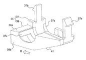
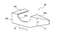
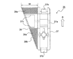
図4は、カール矯正部材35を用紙幅方向の外側から見た斜視図であり、図5は、カール矯正部材35を構成する支持部37、図6は、カール矯正部材35を構成する押圧部39の斜視図である。なお、図4〜図6は用紙排出口31の一端側(図2の右端)に配置されるカール矯正部材35について示しているが、用紙排出口31の他端側(図2の左端)に配置されるカール矯正部材35についても左右対称である以外は全く同様の構成である。カール矯正部材35は、上搬送ガイド32aに取り付けられる支持部37と、支持部37に固定される押圧部39とで構成される(図5、図6参照)。
4 is a perspective view of the
支持部37は樹脂製であり、本体部37aと、本体部37aから上向きに突出する2本の係合爪37bと、本体部37aから水平方向に突出する支持片37cと、を有する。本体部37aには排出ローラー17aの回転軸17a1(図3参照)との干渉を防ぐための円弧状の第1切り欠き部40a(図5参照)が形成されている。係合爪37bは、上搬送ガイド32aに形成された係合孔50(図3参照)に係合する。支持片37cは、押圧部39の固定片39aが接着固定される。支持片37cは、排出ローラー17aの回転軸17a1との干渉を防ぐために用紙排出方向(矢印B方向)において2つに分割されている(図5、図6参照)。
The
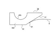
押圧部39はゴム等の弾性材料で形成されており、支持部37の支持片37cに接着固定される固定片39aと、接着部39aの一端から垂直下向きに延在する押圧片39bとを有する。押圧片39bには、用紙排出方向に対し上流側から下流側(図6の矢印B方向)に向かって高さ(固定片39aからの突出量d)が大きくなる傾斜部41が形成されており、傾斜部41の下流側には突出量dが最大となる略水平な突出部42が形成されている。また、押圧片39bには、排出ローラー17aの回転軸17a1との干渉を防ぐための円弧状の第2切り欠き部40bが形成されている。
The
図7は、カール矯正部材35を上方から見た平面図であり、図8は、用紙排出口31の上面31aに装着されたカール矯正部材35を用紙排出方向の上流側から見た図である。図7に示すように、押圧片39bは用紙排出方向(矢印B方向)に対し上流側から下流側(図7の下から上、図8の紙面手前側から奥側)に向かって用紙幅方向の外側に傾斜するように配置されている。また、押圧片39bの下端部(傾斜部41を除く水平部分)は、排出ローラー対17のニップ部N(図3参照)よりも所定量(ここでは5mm)下方に突出しており、用紙排出方向の上流側から下流側に亘ってニップ部Nと重なる位置に配置されている。
7 is a plan view of the
次に、カール矯正部材35によって用紙の幅方向両端部に発生する上向きのカールが矯正される原理について説明する。図9は、用紙Sの先端S1が接触した押圧片39bの側面図であり、図10は、用紙Sの先端S1が接触した押圧片39bを用紙排出方向上流側から見た斜視図である。用紙搬送路16を搬送されてきた用紙Sの先端S1は、カール矯正部材35の押圧片39bに形成された傾斜部41に接触する。そして、用紙Sは押圧片39bに引っ掛かることなく傾斜部41に沿って搬送方向下流側へ円滑に搬送される。
Next, the principle of correcting the upward curl generated at both ends in the width direction of the paper by the
ここで、図7に示したように、押圧片39bは用紙排出方向(矢印B方向)に対し上流側から下流側に向かって用紙幅方向の外側に傾斜している。その結果、用紙Sが排出されていくにつれて、押圧片39bの接触位置が用紙Sの幅方向外側に移動する。これにより、用紙Sの幅方向両端部が押圧片39bによって内側から外側に向かって押し広げられつつ下向きに押圧されるため、用紙Sの幅方向両端部に発生する上カールを効果的に矯正することができる。
Here, as shown in FIG. 7, the
カール矯正部材35は、用紙幅方向の最も外側に位置する排出ローラー対17の外側から用紙の幅方向両端部までの間において、用紙のカール部分に対向する位置に配置される。具体的には、例えばA4サイズの用紙の場合、用紙幅は297mmであり、用紙の幅方向両端部は用紙のセンターから148.5mmの位置にある。また、上カールの発生する位置は用紙の幅方向両端部から30mm程度である。そこで、カール矯正部材35の押圧片39bを、排出方向上流側の端部(図7の下端部)が用紙のセンターから118.5mmの位置となるように配置すればよい。
The
また、図7に示す押圧片39bの下流側端部の幅W(上流側端部から下流側端部までの用紙の接触幅)を30mm以上とすることで、カール部分の全域が押圧片39bに確実に接触するため、カール矯正効果がより向上する。
Further, by setting the width W of the downstream end portion of the
さらに、押圧部39が上端縁を支点として用紙幅方向に弾性変形可能であるため、図10に示すように用紙Sの先端が接触したとき押圧片39bが用紙幅方向(図10の矢印方向)に撓む。これにより、用紙Sが押圧片39bに接触したときの衝撃が緩和され、用紙Sの先端部のめくれが発生することなく上カールを矯正することができる。
Further, since the
その他本発明は、上記実施形態に限定されず、本発明の趣旨を逸脱しない範囲で種々の変更が可能である。例えば、上記実施形態では、支持部37の係合爪37bが係合する係合孔50を上搬送ガイド32aの用紙幅方向の両端部に2箇所ずつ(用紙幅方向に1箇所ずつ)設けているが、係合孔50を複数種の用紙サイズの両端縁近傍に対向する用紙幅方向の複数箇所に形成しておけば、排出される用紙のサイズに応じてカール矯正部材35を付け替えることで、複数種の用紙に発生する上カールを矯正することができる。
In addition, this invention is not limited to the said embodiment, A various change is possible in the range which does not deviate from the meaning of this invention. For example, in the above-described embodiment, the engagement holes 50 with which the
また、本発明は図1に示したようなモノクロプリンターに限らず、カラープリンター、モノクロ及びカラー複写機、デジタル複合機、或いはファクシミリ等、他のタイプの画像形成装置や、画像形成装置に連結される用紙後処理装置にも適用できるのはもちろんである。 The present invention is not limited to the monochrome printer as shown in FIG. 1, but is connected to other types of image forming apparatuses such as color printers, monochrome and color copiers, digital multifunction peripherals, facsimiles, and the like, and image forming apparatuses. Of course, the present invention can also be applied to a paper post-processing apparatus.
本発明は、シート状の用紙や原稿を排出するシート排出装置に利用可能である。本発明の利用により、シートの幅方向端部に生じる上向きのカールを効果的に矯正可能なシート排出装置及びそれを備えた画像形成装置を提供することができる。 The present invention can be used in a sheet discharge device that discharges sheet-like paper or a document. By utilizing the present invention, it is possible to provide a sheet discharge device capable of effectively correcting upward curling generated at the end in the width direction of the sheet, and an image forming apparatus including the sheet discharge device.
15 定着装置
16 用紙搬送路(シート搬送路)
17 排出ローラー対
17a 排出ローラー
17b 排出コロ
18 排出トレイ
30 用紙排出装置(シート排出装置)
31 用紙排出口(シート排出口)
32 搬送ガイド
32a 上搬送ガイド
32b 下搬送ガイド
33 コルゲーション部材
35 カール矯正部材
37 支持部
37a 本体部
37b 係合爪
37c 支持片
39 押圧部
39a 固定片
39b 押圧片
41 傾斜部
42 突出部
100 画像形成装置
P 画像形成部
15
17
31 Paper outlet (sheet outlet)
32
Claims (7)
前記シートの上面に対向する上搬送ガイドと、前記シートの下面に対向する下搬送ガイドとで構成され、前記シート排出口にシートを案内する搬送ガイドと、
前記シート排出口の近傍に設けられた複数の排出ローラー対と、
を備え、排出トレイ上にシートを順次排出して積載するシート排出装置において、
前記排出ローラー対のうちシート幅方向の最も外側に配置された前記排出ローラー対から前記排出ローラー対を通過する前記シートの幅方向両端縁までの間に、前記シートを上方から押圧して上向きのカールを矯正するカール矯正部材が設けられており、
前記カール矯正部材は、前記排出ローラー対のニップ部よりも下方まで略垂直に突出して前記シートの上面に接触する板状の押圧片を有し、前記押圧片は、シート排出方向の上流側から下流側に向かってシート幅方向の外側に傾斜するように配置されていることを特徴とするシート排出装置。 A sheet discharge port through which the sheet is discharged;
A conveyance guide configured to include an upper conveyance guide opposed to the upper surface of the sheet and a lower conveyance guide opposed to the lower surface of the sheet, and to guide the sheet to the sheet discharge port;
A plurality of discharge roller pairs provided in the vicinity of the sheet discharge port;
In a sheet discharge device that sequentially discharges and stacks sheets on a discharge tray,
The sheet is pressed upward from above between the discharge roller pair arranged on the outermost side in the sheet width direction from the discharge roller pair to both ends in the width direction of the sheet passing through the discharge roller pair. A curl correction member that corrects curl is provided,
The curl correction member has a plate-like pressing piece that protrudes substantially vertically below the nip portion of the discharge roller pair and contacts the upper surface of the sheet, and the pressing piece is from the upstream side in the sheet discharging direction. A sheet discharging apparatus, wherein the sheet discharging apparatus is disposed so as to be inclined outward in the sheet width direction toward the downstream side.
Priority Applications (1)
| Application Number | Priority Date | Filing Date | Title |
|---|---|---|---|
| JP2016098391A JP2017206331A (en) | 2016-05-17 | 2016-05-17 | Sheet discharge device and image formation apparatus having the same |
Applications Claiming Priority (1)
| Application Number | Priority Date | Filing Date | Title |
|---|---|---|---|
| JP2016098391A JP2017206331A (en) | 2016-05-17 | 2016-05-17 | Sheet discharge device and image formation apparatus having the same |
Publications (1)
| Publication Number | Publication Date |
|---|---|
| JP2017206331A true JP2017206331A (en) | 2017-11-24 |
Family
ID=60416231
Family Applications (1)
| Application Number | Title | Priority Date | Filing Date |
|---|---|---|---|
| JP2016098391A Pending JP2017206331A (en) | 2016-05-17 | 2016-05-17 | Sheet discharge device and image formation apparatus having the same |
Country Status (1)
| Country | Link |
|---|---|
| JP (1) | JP2017206331A (en) |
-
2016
- 2016-05-17 JP JP2016098391A patent/JP2017206331A/en active Pending
Similar Documents
| Publication | Publication Date | Title |
|---|---|---|
| US10981738B2 (en) | Sheet feeding apparatus and image forming apparatus | |
| JP5306025B2 (en) | Sheet conveying apparatus and electrophotographic apparatus | |
| CN104803219B (en) | Paper feed and image processing system | |
| JP5823454B2 (en) | Paper feeding device and image forming apparatus | |
| JP6572819B2 (en) | Sheet stacking tray, sheet post-processing apparatus including the same, and image forming apparatus | |
| US9483007B2 (en) | Image forming apparatus | |
| JP5401887B2 (en) | Image forming apparatus | |
| JP6021865B2 (en) | Sheet discharging apparatus and image forming apparatus having the same | |
| US10358312B2 (en) | Sheet processing apparatus and image forming apparatus | |
| CN109748132B (en) | Sheet discharge device and image forming apparatus provided with the same | |
| US9857741B2 (en) | Image forming apparatus including main ribs respectively corresponding to sheets of plural sizes and sub-rib lower than main rib | |
| JP6204307B2 (en) | Image forming apparatus | |
| JP2017206331A (en) | Sheet discharge device and image formation apparatus having the same | |
| JP2001226016A (en) | Image forming device | |
| JP2007106524A (en) | Sheet delivery mechanism and image forming device equipped with it | |
| JP7512059B2 (en) | Sheet feeding device and image forming apparatus | |
| JP7815381B2 (en) | Sheet ejection device and image forming apparatus | |
| JPH05134563A (en) | Paper guide device | |
| JP2022112556A (en) | Sheet ejection device and image forming apparatus provided with the same | |
| JP2007217156A (en) | Sheet delivery mechanism and image forming device equipped with it | |
| JP4037296B2 (en) | Document feeder | |
| JP4569907B2 (en) | Medium conveying apparatus and image forming apparatus | |
| JP6303807B2 (en) | Fixing apparatus and image forming apparatus | |
| JP6380354B2 (en) | Image forming apparatus | |
| JP2009292631A (en) | Paper sheet conveying device and image forming device |