JP2017206902A - Cover thickness measurement device of reinforcement - Google Patents
Cover thickness measurement device of reinforcement Download PDFInfo
- Publication number
- JP2017206902A JP2017206902A JP2016101088A JP2016101088A JP2017206902A JP 2017206902 A JP2017206902 A JP 2017206902A JP 2016101088 A JP2016101088 A JP 2016101088A JP 2016101088 A JP2016101088 A JP 2016101088A JP 2017206902 A JP2017206902 A JP 2017206902A
- Authority
- JP
- Japan
- Prior art keywords
- cover thickness
- distance
- rod
- reference plate
- reinforcing bar
- Prior art date
- Legal status (The legal status is an assumption and is not a legal conclusion. Google has not performed a legal analysis and makes no representation as to the accuracy of the status listed.)
- Pending
Links
Images

Landscapes
- Conveying And Assembling Of Building Elements In Situ (AREA)
- Length Measuring Devices By Optical Means (AREA)
Abstract
Description
本発明は、鉄筋と型枠の間に形成されるコンクリートの厚さに相当する鉄筋のかぶり厚をコンクリート打設前に計測する鉄筋のかぶり厚計測装置に関する。 The present invention relates to a rebar cover thickness measuring apparatus that measures the cover thickness of a rebar corresponding to the thickness of concrete formed between the rebar and a formwork before placing the concrete.
従来、鉄筋と型枠の間に形成されるコンクリートの厚さに相当する鉄筋のかぶり厚を、コンクリート打設前に計測する装置として、両面反射鏡を挟んで相対する位置に2つのレーザー変位計が設置されている変位計本体を備えたものが知られている(例えば、特許文献1参照。)。
この装置は、変位計本体を型枠に沿って移動させる過程で、一方のレーザー変位計が型枠表面との距離を連続的に計測したデータと、他方のレーザー変位計が鉄筋表面との距離を連続的に計測したデータを取得し、それらデータを加算して鉄筋のかぶり厚を計測するようになっている。
Conventionally, as a device for measuring the cover thickness of a reinforcing bar corresponding to the thickness of the concrete formed between the reinforcing bar and the formwork before placing the concrete, two laser displacement meters are located at opposite positions with a double-sided reflector in between. The thing provided with the displacement meter main body in which is installed is known (for example, refer to patent documents 1).
This device is a process in which the displacement gauge body is moved along the mold, and one laser displacement gauge continuously measures the distance from the mold surface, and the other laser displacement gauge is the distance from the rebar surface. The data which measured continuously is acquired, and those data are added and the cover thickness of a reinforcing bar is measured.
しかしながら、上記特許文献1の装置は、他方のレーザー変位計が鉄筋表面との距離を連続的に計測したデータにおける極小点に対応する箇所をその鉄筋表面における最も型枠に近い箇所であるとして、「鉄筋のかぶり厚」を計測するようになっているので、任意の鉄筋1本のかぶり厚を計測するには不向きな装置であった。
これは、鉄筋表面が曲面であり、その鉄筋表面における最も型枠に近い箇所との距離をレーザー変位計でピンポイントに計測することは困難であるため、型枠に沿って鉄筋を連続的に計測するしかなかったことによる。
つまり、この装置で任意の鉄筋のかぶり厚を計測するには、鉄筋を連続的に計測する必要があり、操作が煩雑である。また、2つのレーザー変位計を使用するため、コストが高いという課題がある。
However, in the apparatus of Patent Document 1, the position corresponding to the minimum point in the data obtained by continuously measuring the distance between the other laser displacement meter and the rebar surface is the position closest to the formwork on the rebar surface. Since “rebar cover thickness” is to be measured, the apparatus is not suitable for measuring the cover thickness of an arbitrary reinforcing bar.
This is because the surface of the reinforcing bar is a curved surface, and it is difficult to pinpoint the distance from the point closest to the mold on the surface of the reinforcing bar with a laser displacement meter. Because there was no choice but to measure.
That is, in order to measure the cover thickness of an arbitrary reinforcing bar with this apparatus, it is necessary to continuously measure the reinforcing bar, and the operation is complicated. Moreover, since two laser displacement meters are used, there is a problem that the cost is high.
本発明の目的は、任意の鉄筋のかぶり厚を容易に計測することができる鉄筋のかぶり厚計測装置を提供することである。 An object of the present invention is to provide a rebar cover thickness measuring apparatus capable of easily measuring a cover thickness of an arbitrary rebar.
上記目的を達成するため、この発明は、
レーザー光を使用して鉄筋と型枠の間に形成されるコンクリートの厚さに相当する鉄筋のかぶり厚を計測する鉄筋のかぶり厚計測装置であって、
伸縮可能な棒状部材と、
前記棒状部材の基端部側に取り付けられたレーザー距離計と、
前記棒状部材の先端部に取り付けられ、前記棒状部材に対し垂直な基準板と、前記基準板に対し垂直に設けられた当接板とを有し、前記鉄筋と前記型枠の間に挿し入れられる計測点当接部材と、
前記当接板に対し45°の角度を成すとともに、前記基準板に対し45°の角度を成して前記基準板に並ぶ位置であって、前記基準板と前記当接板とが交差する線と鏡面とが同一面上にある配置で、前記鏡面を前記レーザー距離計側に向けて前記計測点当接部材に固定された鏡と、
を備え、
前記レーザー距離計は、前記基準板に向けてレーザー光を照射する位置と、前記鏡面に向けてレーザー光を照射する位置とに切り替え可能に取り付けられているようにした。
In order to achieve the above object, the present invention
A rebar cover thickness measuring device that uses a laser beam to measure the rebar cover thickness equivalent to the thickness of the concrete formed between the rebar and the formwork,
An extendable rod-shaped member;
A laser rangefinder attached to the base end side of the rod-shaped member;
A reference plate that is attached to the tip of the rod-shaped member and is perpendicular to the rod-shaped member, and a contact plate that is provided perpendicular to the reference plate, and is inserted between the reinforcing bar and the formwork A measuring point contact member
A line that forms an angle of 45 ° with the contact plate and is aligned with the reference plate at an angle of 45 ° with the reference plate and intersects the reference plate and the contact plate And a mirror fixed on the measurement point abutting member with the mirror surface facing the laser distance meter side in an arrangement where the mirror surface is on the same plane,
With
The laser distance meter is attached so as to be switchable between a position for irradiating laser light toward the reference plate and a position for irradiating laser light toward the mirror surface.
かかる構成の鉄筋のかぶり厚計測装置であれば、計測対象の鉄筋が配筋されている箇所に応じて棒状部材の長さを調整し、鉄筋と型枠の間に計測点当接部材を挿し入れることができる。
そして、計測点当接部材の当接板が型枠と平行になるように、計測対象の鉄筋に計測点当接部材(当接板)を当接させた状態で、鏡の鏡面に向けてレーザー光を照射する位置(第1の位置)と、基準板に向けてレーザー光を照射する位置(第2の位置)とにレーザー距離計の配置を切り替えて、それぞれの配置でレーザー距離計による測距を行うことができる。このとき、計測点当接部材に鏡が固定されている面を型枠に向けて、計測対象の鉄筋に計測点当接部材を当接させている。
この測距を行った後、鏡でレーザー光を90°曲げた光路に対応する型枠までの距離(第1の位置で計測した値)から基準板までの距離(第2の位置で計測した値)を減算すれば、鉄筋と型枠の間の距離に相当する鉄筋のかぶり厚が得られる。
このように、鉄筋のかぶり厚計測装置を用いれば、計測対象となった任意の鉄筋のかぶり厚を容易に計測することができる。
In the reinforcing bar cover thickness measuring apparatus having such a configuration, the length of the bar-shaped member is adjusted according to the location where the reinforcing bar to be measured is arranged, and the measurement point contact member is inserted between the reinforcing bar and the formwork. Can be put.
Then, with the measurement point contact member (contact plate) in contact with the reinforcing bar to be measured so that the contact plate of the measurement point contact member is parallel to the mold, it faces the mirror surface of the mirror The laser distance meter is switched between the position where the laser light is irradiated (first position) and the position where the laser light is irradiated toward the reference plate (second position). Distance measurement can be performed. At this time, the surface on which the mirror is fixed to the measurement point contact member faces the mold, and the measurement point contact member is brought into contact with the rebar to be measured.
After performing this distance measurement, the distance from the distance (value measured at the first position) to the mold corresponding to the optical path obtained by bending the laser light by 90 ° with a mirror to the reference plate (measured at the second position). If the value is subtracted, the cover thickness of the reinforcing bar corresponding to the distance between the reinforcing bar and the formwork is obtained.
In this way, by using the reinforcing bar cover thickness measuring apparatus, it is possible to easily measure the cover thickness of an arbitrary reinforcing bar as a measurement target.
また、望ましくは、
前記計測点当接部材は、前記棒状部材と直交する方向に移動可能に取り付けられているようにする。
例えば、レーザー距離計の機種毎にレーザー光を出射する出射口の位置が異なるので、棒状部材の基端部側に取り付けたレーザー距離計に応じて、計測点当接部材の配置を切り替えるようにする。
こうして計測点当接部材の基準板や、計測点当接部材に固定されている鏡の配置を切り替えるように調整すれば、レーザー距離計が適切に、基準板に向けてレーザー光を照射したり、鏡の鏡面に向けてレーザー光を照射したりすることが可能になる。
Also, preferably
The measurement point contact member is attached so as to be movable in a direction orthogonal to the rod-shaped member.
For example, since the position of the exit from which laser light is emitted differs depending on the model of the laser distance meter, the arrangement of the measurement point contact member is switched according to the laser distance meter attached to the base end side of the rod-shaped member. To do.
By adjusting the reference plate of the measurement point contact member and the arrangement of the mirror fixed to the measurement point contact member in this way, the laser rangefinder can properly irradiate the reference plate with laser light. It becomes possible to irradiate laser light toward the mirror surface of the mirror.
また、望ましくは、
前記当接板に固設された磁石を備えるようにする。
計測点当接部材の当接板に磁石が固設されていれば、計測対象の鉄筋に当接板を当接させた際、磁石の磁力で当接板を鉄筋にくっつけて仮止めできるので、鉄筋のかぶり厚計測装置の計測姿勢を安定させることができる。
Also, preferably
A magnet fixed to the contact plate is provided.
If a magnet is fixed to the contact plate of the measurement point contact member, when the contact plate is brought into contact with the reinforcing bar to be measured, the contact plate can be temporarily attached to the reinforcing bar by the magnet's magnetic force. The measurement posture of the rebar cover thickness measuring device can be stabilized.
本発明によれば、任意の鉄筋のかぶり厚を容易に計測することができる。 According to the present invention, the cover thickness of any reinforcing bar can be easily measured.
以下、図面を参照して、本発明に係る鉄筋のかぶり厚計測装置の実施形態について詳細に説明する。但し、以下に述べる実施形態には、本発明を実施するために技術的に好ましい種々の限定が付されているが、本発明の範囲を以下の実施形態及び図示例に限定するものではない。 DESCRIPTION OF EMBODIMENTS Hereinafter, embodiments of a reinforcing bar cover thickness measuring apparatus according to the present invention will be described in detail with reference to the drawings. However, the embodiments described below are given various technically preferable limitations for carrying out the present invention, but the scope of the present invention is not limited to the following embodiments and illustrated examples.
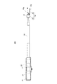
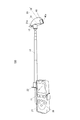
図1は、本実施形態の鉄筋のかぶり厚計測装置100を示す側面図である。図2、図3は、本実施形態の鉄筋のかぶり厚計測装置100を示す斜視図である。
鉄筋のかぶり厚計測装置100は、鉄筋Rと型枠Wの間に形成されるコンクリートの厚さに相当する鉄筋のかぶり厚を計測するのに用いる装置である。
FIG. 1 is a side view showing a reinforcing bar cover
The reinforcing bar cover
本実施形態の鉄筋のかぶり厚計測装置100(以下、かぶり厚計測装置100という)は、図1〜図3に示すように、伸縮可能な棒状部材10と、棒状部材10の基端部11側に取り付けられたレーザー距離計20と、棒状部材10の先端部12に取り付けられた計測点当接部材30と、計測点当接部材30に固定された鏡40等を備えて構成されている。
As shown in FIGS. 1 to 3, a reinforcing bar cover thickness measuring device 100 (hereinafter referred to as a cover thickness measuring device 100) according to the present embodiment includes an extendable rod-
棒状部材10は、複数の節を有している伸縮式の棒状部材であり、例えば、指し棒・指示棒などと称されて一般的に知られている部材である。
この棒状部材10を収縮させた状態で、かぶり厚計測装置100の全長は約450mmになり、棒状部材10を伸長させた状態で、かぶり厚計測装置100の全長は約1500mmになる。つまり、かぶり厚計測装置100は、約450mm〜約1500mmの範囲で長さ調整可能になっている。
この棒状部材10の基端部11に、レーザー距離計20を保持するホルダー21が配設されている。
The rod-
When the rod-
A
ホルダー21には、図3に示すように、長穴22aが形成されている保持片22が設けられている。このホルダー21の保持片22に棒状部材10が取り付けられるようにして、棒状部材10の基端部11にレーザー距離計20が取り付けられている。
保持片22は、ホルダー21の側面に垂直に立設されており、この保持片22の長穴22aに沿って棒状部材10がスライド移動可能にホルダー21に取り付けられている。なお、保持片22に対し棒状部材10は垂直に配されている。
As shown in FIG. 3, the
The
レーザー距離計20はホルダー21に交換可能に取り付けられており、棒状部材10の基端部11に取り付けるレーザー距離計20をユーザーが所望するレーザー距離計20に付け替えて使用することができる。
そして、保持片22の長穴22aに沿って棒状部材10をスライド移動させることで、レーザー距離計20の配置を相対的に棒状部材10と直交する方向に切り替えることが可能になっている。
こうして、レーザー距離計20は、後述する鏡40の鏡面40aに向けてレーザー光を照射する第1の位置と、後述する基準板31に向けてレーザー光を照射する第2の位置とに切り替え可能とされている。
The
Then, the rod-
In this way, the
計測点当接部材30は、棒状部材10に対し垂直な基準板31と、基準板31に対し垂直に設けられた当接板32とを有している。この基準板31に棒状部材10が取り付けられるようにして、棒状部材10の先端部12に計測点当接部材30が取り付けられている。
具体的には、図2に示すように、基準板31には長穴31aが形成されており、その長穴31aに沿って計測点当接部材30はスライド移動可能に棒状部材10に取り付けられている。
つまり、計測点当接部材30は、棒状部材10と直交する方向に移動可能であって、その固定位置を変更可能に取り付けられている。
例えば、レーザー距離計20の機種毎に、レーザー光を出射する出射口の位置が異なるので、ホルダー21に取り付けたレーザー距離計20に応じて、後述する鏡40の位置を調整するように、計測点当接部材30の配置を切り替えることが可能になっている。
The measurement
Specifically, as shown in FIG. 2, a
That is, the measurement
For example, since the position of the exit from which the laser beam is emitted differs depending on the model of the
また、計測点当接部材30の当接板32における、後述する鏡40が固定されている面とは反対側の面は、計測対象の鉄筋Rに当接させる当接面32aになっている。
In addition, the surface of the
鏡40は、当接板32に対し45°の角度を成すとともに、基準板31に対し45°の角度を成しており、その鏡面40aをレーザー距離計20側に向けた姿勢で、計測点当接部材30における基準板31に並ぶ位置に固定されている。
例えば、鉄板などの金属板に折り曲げ加工を施して計測点当接部材30が形成されている場合、基準板31と当接板32は90°の角度を成すように折り曲げられており、また基準板31に並ぶ金属片の一部が当接板32に対し45°の角度を成すように折り曲げられ、そこに鏡40が接着されるなどして固定されている。
特に、この鏡40は、基準板31と当接板32とが交差する線と鏡面40aとが同一面上にある配置で計測点当接部材30に固定されている。
The
For example, when the measurement
In particular, the
また、図3に示すように、計測点当接部材30の当接板32には、磁石50が固設されている。
磁石50は、当接面32aが平坦面となるように、当接板32に埋め込まれるように固設されている。なお、磁石50の磁力にもよるが、当接板32における鏡40が固定されている面に磁石50を固設してもよい。
このように当接板32に磁石50が固設されていれば、計測対象の鉄筋Rに当接板32を当接させた際、磁石50の磁力で当接板32を鉄筋Rにくっつけて仮止めできるので、かぶり厚計測装置100の計測姿勢を安定させることができる。
本実施形態では、5つの磁石50を略T字状に並べて固設している。こうすることで、縦方向の鉄筋Rに対しても、横方向の鉄筋Rに対しても、当接板32を好適に磁力で仮止めできる。
Further, as shown in FIG. 3, a
The
If the
In the present embodiment, five
次に、かぶり厚計測装置100を使用した、鉄筋のかぶり厚の計測方法について説明する。
Next, a method for measuring the cover thickness of the reinforcing bar using the cover
まず、計測対象の鉄筋Rが配筋されている箇所に応じて、棒状部材10の長さを調整する。
次いで、鉄筋Rと型枠Wの間に計測点当接部材30を挿し入れ、計測対象の鉄筋Rに当接板32の当接面32aを当接させる。
このとき、当接板32が型枠Wと平行になり、基準板31が型枠Wと垂直になるように、棒状部材10の向きを調整する。
First, the length of the rod-shaped
Next, the measurement
At this time, the orientation of the rod-shaped
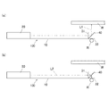
次いで、図4(a)に示すように、鏡40の鏡面40aに向けてレーザー光を照射する第1の位置に配したレーザー距離計20による測距を行い、鏡40でレーザー光を90°曲げた光路に対応する型枠Wまでの距離L1を計測する。
次いで、図4(b)に示すように、基準板31に向けてレーザー光を照射する第2の位置にレーザー距離計20の配置を切り替え、そのレーザー距離計20による測距を行い、基準板31までの距離L2を計測する。
そして、鏡40でレーザー光を90°曲げた光路に対応する型枠Wまでの距離L1から基準板31までの距離L2を減算する。
こうして距離L1の値から距離L2の値を減算して得られる寸法が、鉄筋Rと型枠Wの間の距離であり、この距離が鉄筋のかぶり厚である。
これは、計測点当接部材30に固定されている鏡40が、当接板32に対し45°の角度を成すとともに、基準板31に対し45°の角度を成しているので、図4(b)に示すように、レーザー光が鏡40(鏡面40a)に当たったポイントから基準板31までの寸法と、そのポイントから鉄筋Rまでの寸法が等しいことによる。
Next, as shown in FIG. 4A, distance measurement is performed by the
Next, as shown in FIG. 4B, the arrangement of the
Then, the distance L2 to the
The dimension obtained by subtracting the value of the distance L2 from the value of the distance L1 is the distance between the reinforcing bar R and the formwork W, and this distance is the cover thickness of the reinforcing bar.
This is because the
以上のように、本実施形態のかぶり厚計測装置100によれば、当接板32が型枠Wと平行になるように、計測対象の鉄筋Rに当接板32の当接面32aを当接させた状態で、鏡40の鏡面40aに向けてレーザー光を照射する第1の位置と、基準板31に向けてレーザー光を照射する第2の位置とにレーザー距離計20の配置を切り替えて、それぞれの配置でレーザー距離計20による測距を行った後、第1の位置で計測した距離L1の値から第2の位置で計測した距離L2の値を減算するようにして、鉄筋のかぶり厚を計測することができる。
このように、本実施形態のかぶり厚計測装置100を用いれば、計測対象となった任意の鉄筋Rのかぶり厚を容易に計測することができる。
As described above, according to the cover
Thus, if the cover
また、かぶり厚計測装置100を使用して、上述した手法による計測を複数回行って得られたかぶり厚の最小値を採用するようにすれば、より正確に鉄筋のかぶり厚を計測することができる。
こうすることで、より確実に当接板32が型枠Wと平行になった状態で、かぶり厚を計測することが可能になる。
Moreover, if the minimum value of the cover thickness obtained by performing the measurement by the above-described method a plurality of times using the cover
By doing so, it is possible to measure the cover thickness in a state where the
また、保持片22の長穴22aに沿って棒状部材10をスライド移動させるようにして、レーザー距離計20の配置を棒状部材10と直交する方向に切り替えて、レーザー距離計20が、鏡40の鏡面40aに向けてレーザー光を照射する第1の位置と、基準板31に向けてレーザー光を照射する第2の位置とに切り替えることに限らず、例えば、保持片22を僅かに撓ませるようにしてホルダー21に取り付けられているレーザー距離計20の向きを微調整し、レーザー距離計20から鏡面40aに向けてレーザー光を照射したり基準板31に向けてレーザー光を照射したりするようにしてもよい。
例えば、レーザー距離計20と鏡40との距離が1000mm以上離れている計測を行う場合や、0.1mm単位の誤差が問題にならない箇所の計測を行う場合には、このようにレーザー距離計20の向きを微調整して、鏡40でレーザー光を90°曲げた光路に対応する型枠Wまでの距離L1と、基準板31までの距離L2を計測して、鉄筋のかぶり厚を計測するようにしてもよい。
In addition, the rod-shaped
For example, in the case of performing measurement where the distance between the
なお、本発明の適用は上述した実施形態に限定されることなく、本発明の趣旨を逸脱しない範囲で適宜変更可能である。 The application of the present invention is not limited to the above-described embodiment, and can be appropriately changed without departing from the spirit of the present invention.
10 棒状部材
11 基端部
12 先端部
20 レーザー距離計
21 ホルダー
22 保持片
22a 長穴
30 計測点当接部材
31 基準板
31a 長穴
32 当接板
32a 当接面
40 鏡
40a 鏡面
50 磁石
100 鉄筋のかぶり厚計測装置
R 鉄筋
W 型枠
L1、L2 距離
DESCRIPTION OF
Claims (3)
伸縮可能な棒状部材と、
前記棒状部材の基端部側に取り付けられたレーザー距離計と、
前記棒状部材の先端部に取り付けられ、前記棒状部材に対し垂直な基準板と、前記基準板に対し垂直に設けられた当接板とを有し、前記鉄筋と前記型枠の間に挿し入れられる計測点当接部材と、
前記当接板に対し45°の角度を成すとともに、前記基準板に対し45°の角度を成して前記基準板に並ぶ位置であって、前記基準板と前記当接板とが交差する線と鏡面とが同一面上にある配置で、前記鏡面を前記レーザー距離計側に向けて前記計測点当接部材に固定された鏡と、
を備え、
前記レーザー距離計は、前記基準板に向けてレーザー光を照射する位置と、前記鏡面に向けてレーザー光を照射する位置とに切り替え可能に取り付けられていることを特徴とする鉄筋のかぶり厚計測装置。 A rebar cover thickness measuring device for measuring the rebar cover thickness corresponding to the thickness of the concrete formed between the rebar and the formwork,
An extendable rod-shaped member;
A laser rangefinder attached to the base end side of the rod-shaped member;
A reference plate that is attached to the tip of the rod-shaped member and is perpendicular to the rod-shaped member, and a contact plate that is provided perpendicular to the reference plate, and is inserted between the reinforcing bar and the formwork A measuring point contact member
A line that forms an angle of 45 ° with the contact plate and is aligned with the reference plate at an angle of 45 ° with the reference plate and intersects the reference plate and the contact plate And a mirror fixed on the measurement point abutting member with the mirror surface facing the laser distance meter side in an arrangement where the mirror surface is on the same plane,
With
The laser distance meter is mounted so as to be switchable between a position for irradiating laser light toward the reference plate and a position for irradiating laser light toward the mirror surface. apparatus.
Priority Applications (1)
| Application Number | Priority Date | Filing Date | Title |
|---|---|---|---|
| JP2016101088A JP2017206902A (en) | 2016-05-20 | 2016-05-20 | Cover thickness measurement device of reinforcement |
Applications Claiming Priority (1)
| Application Number | Priority Date | Filing Date | Title |
|---|---|---|---|
| JP2016101088A JP2017206902A (en) | 2016-05-20 | 2016-05-20 | Cover thickness measurement device of reinforcement |
Publications (1)
| Publication Number | Publication Date |
|---|---|
| JP2017206902A true JP2017206902A (en) | 2017-11-24 |
Family
ID=60414864
Family Applications (1)
| Application Number | Title | Priority Date | Filing Date |
|---|---|---|---|
| JP2016101088A Pending JP2017206902A (en) | 2016-05-20 | 2016-05-20 | Cover thickness measurement device of reinforcement |
Country Status (1)
| Country | Link |
|---|---|
| JP (1) | JP2017206902A (en) |
Cited By (2)
| Publication number | Priority date | Publication date | Assignee | Title |
|---|---|---|---|---|
| CN112502359A (en) * | 2020-12-15 | 2021-03-16 | 中铁大桥局第九工程有限公司 | Device for detecting position of reinforcing steel bar in reinforced concrete construction |
| CN115507796A (en) * | 2022-09-14 | 2022-12-23 | 保利长大工程有限公司 | Detector for measuring thickness of protective layer between steel bar and template |
-
2016
- 2016-05-20 JP JP2016101088A patent/JP2017206902A/en active Pending
Cited By (3)
| Publication number | Priority date | Publication date | Assignee | Title |
|---|---|---|---|---|
| CN112502359A (en) * | 2020-12-15 | 2021-03-16 | 中铁大桥局第九工程有限公司 | Device for detecting position of reinforcing steel bar in reinforced concrete construction |
| CN115507796A (en) * | 2022-09-14 | 2022-12-23 | 保利长大工程有限公司 | Detector for measuring thickness of protective layer between steel bar and template |
| CN115507796B (en) * | 2022-09-14 | 2023-06-27 | 保利长大工程有限公司 | Detector for measuring thickness of protective layer between reinforcing steel bar and template |
Similar Documents
| Publication | Publication Date | Title |
|---|---|---|
| JP2011081014A (en) | Measuring probe used for coordinate measuring machine | |
| JP6401050B2 (en) | Rail wear measuring instrument | |
| JP2013160762A5 (en) | ||
| JP2017042876A (en) | Movable type punch | |
| KR20110009323U (en) | Length measuring device | |
| JP6936951B2 (en) | Bending angle measuring device | |
| JP6409041B2 (en) | Level | |
| US2542030A (en) | Magnetically supported indicating bore gauge | |
| CN104439769A (en) | Robot welding perpendicularity measuring mechanism and measuring method | |
| US1737764A (en) | Combined micrometer caliper and depth gauge | |
| JP2013072830A (en) | Bend pipe measurement jig | |
| KR20150000401U (en) | Marking Tool Providing Horizontality Alignment Function and Length Measurement | |
| KR200479321Y1 (en) | Measuring device for large length member | |
| KR102149842B1 (en) | Complex level gauge | |
| US1379116A (en) | Pin-caliper | |
| KR101607202B1 (en) | Multifunction measuring device | |
| JP2006234427A (en) | Flatness measuring method and instrument | |
| JP2005321393A (en) | Marking/tracing instrument | |
| KR101030743B1 (en) | Linear distance measuring device of curved surface part | |
| KR101961992B1 (en) | Apparatus and method to measure diameter of structure | |
| JP2022091495A (en) | Caliper gauge | |
| KR200403983Y1 (en) | target for measurement pipe laying length | |
| JP2014154855A5 (en) | ||
| JP2015215324A (en) | External diameter micrometer guide ring | |
| JP2007147331A (en) | Straightness measurement method and apparatus |