JP2017207194A - 合成樹脂管継手の漏出防止構造 - Google Patents
合成樹脂管継手の漏出防止構造 Download PDFInfo
- Publication number
- JP2017207194A JP2017207194A JP2016197024A JP2016197024A JP2017207194A JP 2017207194 A JP2017207194 A JP 2017207194A JP 2016197024 A JP2016197024 A JP 2016197024A JP 2016197024 A JP2016197024 A JP 2016197024A JP 2017207194 A JP2017207194 A JP 2017207194A
- Authority
- JP
- Japan
- Prior art keywords
- synthetic resin
- ferrule
- general formula
- fitting
- resin pipe
- Prior art date
- Legal status (The legal status is an assumption and is not a legal conclusion. Google has not performed a legal analysis and makes no representation as to the accuracy of the status listed.)
- Granted
Links
Images


Classifications
-
- F—MECHANICAL ENGINEERING; LIGHTING; HEATING; WEAPONS; BLASTING
- F16—ENGINEERING ELEMENTS AND UNITS; GENERAL MEASURES FOR PRODUCING AND MAINTAINING EFFECTIVE FUNCTIONING OF MACHINES OR INSTALLATIONS; THERMAL INSULATION IN GENERAL
- F16L—PIPES; JOINTS OR FITTINGS FOR PIPES; SUPPORTS FOR PIPES, CABLES OR PROTECTIVE TUBING; MEANS FOR THERMAL INSULATION IN GENERAL
- F16L19/00—Joints in which sealing surfaces are pressed together by means of a member, e.g. a swivel nut, screwed on, or into, one of the joint parts
- F16L19/02—Pipe ends provided with collars or flanges, integral with the pipe or not, pressed together by a screwed member
-
- F—MECHANICAL ENGINEERING; LIGHTING; HEATING; WEAPONS; BLASTING
- F16—ENGINEERING ELEMENTS AND UNITS; GENERAL MEASURES FOR PRODUCING AND MAINTAINING EFFECTIVE FUNCTIONING OF MACHINES OR INSTALLATIONS; THERMAL INSULATION IN GENERAL
- F16L—PIPES; JOINTS OR FITTINGS FOR PIPES; SUPPORTS FOR PIPES, CABLES OR PROTECTIVE TUBING; MEANS FOR THERMAL INSULATION IN GENERAL
- F16L19/00—Joints in which sealing surfaces are pressed together by means of a member, e.g. a swivel nut, screwed on, or into, one of the joint parts
- F16L19/005—Joints in which sealing surfaces are pressed together by means of a member, e.g. a swivel nut, screwed on, or into, one of the joint parts comprising locking means for the threaded member
-
- F—MECHANICAL ENGINEERING; LIGHTING; HEATING; WEAPONS; BLASTING
- F16—ENGINEERING ELEMENTS AND UNITS; GENERAL MEASURES FOR PRODUCING AND MAINTAINING EFFECTIVE FUNCTIONING OF MACHINES OR INSTALLATIONS; THERMAL INSULATION IN GENERAL
- F16L—PIPES; JOINTS OR FITTINGS FOR PIPES; SUPPORTS FOR PIPES, CABLES OR PROTECTIVE TUBING; MEANS FOR THERMAL INSULATION IN GENERAL
- F16L19/00—Joints in which sealing surfaces are pressed together by means of a member, e.g. a swivel nut, screwed on, or into, one of the joint parts
- F16L19/02—Pipe ends provided with collars or flanges, integral with the pipe or not, pressed together by a screwed member
- F16L19/0212—Pipe ends provided with collars or flanges, integral with the pipe or not, pressed together by a screwed member using specially adapted sealing means
-
- F—MECHANICAL ENGINEERING; LIGHTING; HEATING; WEAPONS; BLASTING
- F16—ENGINEERING ELEMENTS AND UNITS; GENERAL MEASURES FOR PRODUCING AND MAINTAINING EFFECTIVE FUNCTIONING OF MACHINES OR INSTALLATIONS; THERMAL INSULATION IN GENERAL
- F16L—PIPES; JOINTS OR FITTINGS FOR PIPES; SUPPORTS FOR PIPES, CABLES OR PROTECTIVE TUBING; MEANS FOR THERMAL INSULATION IN GENERAL
- F16L19/00—Joints in which sealing surfaces are pressed together by means of a member, e.g. a swivel nut, screwed on, or into, one of the joint parts
- F16L19/06—Joints in which sealing surfaces are pressed together by means of a member, e.g. a swivel nut, screwed on, or into, one of the joint parts in which radial clamping is obtained by wedging action on non-deformed pipe ends
-
- F—MECHANICAL ENGINEERING; LIGHTING; HEATING; WEAPONS; BLASTING
- F16—ENGINEERING ELEMENTS AND UNITS; GENERAL MEASURES FOR PRODUCING AND MAINTAINING EFFECTIVE FUNCTIONING OF MACHINES OR INSTALLATIONS; THERMAL INSULATION IN GENERAL
- F16L—PIPES; JOINTS OR FITTINGS FOR PIPES; SUPPORTS FOR PIPES, CABLES OR PROTECTIVE TUBING; MEANS FOR THERMAL INSULATION IN GENERAL
- F16L47/00—Connecting arrangements or other fittings specially adapted to be made of plastics or to be used with pipes made of plastics
- F16L47/04—Connecting arrangements or other fittings specially adapted to be made of plastics or to be used with pipes made of plastics with a swivel nut or collar engaging the pipe
- F16L47/041—Connecting arrangements or other fittings specially adapted to be made of plastics or to be used with pipes made of plastics with a swivel nut or collar engaging the pipe the plastic pipe end being flared either before or during the making of the connection
-
- H—ELECTRICITY
- H10—SEMICONDUCTOR DEVICES; ELECTRIC SOLID-STATE DEVICES NOT OTHERWISE PROVIDED FOR
- H10P—GENERIC PROCESSES OR APPARATUS FOR THE MANUFACTURE OR TREATMENT OF DEVICES COVERED BY CLASS H10
- H10P72/00—Handling or holding of wafers, substrates or devices during manufacture or treatment thereof
- H10P72/04—Apparatus for manufacture or treatment
- H10P72/0402—Apparatus for fluid treatment
- H10P72/0406—Apparatus for fluid treatment for cleaning followed by drying, rinsing, stripping, blasting or the like
- H10P72/0411—Apparatus for fluid treatment for cleaning followed by drying, rinsing, stripping, blasting or the like for wet cleaning or washing
-
- H—ELECTRICITY
- H10—SEMICONDUCTOR DEVICES; ELECTRIC SOLID-STATE DEVICES NOT OTHERWISE PROVIDED FOR
- H10P—GENERIC PROCESSES OR APPARATUS FOR THE MANUFACTURE OR TREATMENT OF DEVICES COVERED BY CLASS H10
- H10P95/00—Generic processes or apparatus for manufacture or treatments not covered by the other groups of this subclass
-
- H—ELECTRICITY
- H10—SEMICONDUCTOR DEVICES; ELECTRIC SOLID-STATE DEVICES NOT OTHERWISE PROVIDED FOR
- H10W—GENERIC PACKAGES, INTERCONNECTIONS, CONNECTORS OR OTHER CONSTRUCTIONAL DETAILS OF DEVICES COVERED BY CLASS H10
- H10W72/00—Interconnections or connectors in packages
Landscapes
- Engineering & Computer Science (AREA)
- General Engineering & Computer Science (AREA)
- Mechanical Engineering (AREA)
- Branch Pipes, Bends, And The Like (AREA)
- Joints With Pressure Members (AREA)
- Rigid Pipes And Flexible Pipes (AREA)
Abstract
Description
0.3≦L3/L2≦0.7
2≦A2≦6
0.1≦T3/T2≦0.5
0.8≦T1/L1≦1.2
30≦A1≦60
0.2≦L5/L4≦0.6
0.5≦W2/W1≦0.9
10≦A3≦25
(第1実施形態)
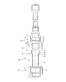
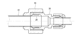
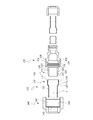
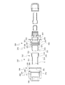
図1は、本発明の第1実施形態による合成樹脂管継手構造を示す分解図であり、図2は、図1の組立図であり、図3は、図1でフェルールの部分拡大図であって、第1実施形態の継手構造は、フェルール20とフィッティング30のラウンド部27、32による合成樹脂管継手の漏出防止構造に関する。第1実施形態の継手構造は、合成樹脂管10、フェルール20、フィッティング30、ナット40等で構成され得る。
0.8≦T1/L1≦1.2
30≦A1≦60
図4は、本発明の第2実施形態による合成樹脂管継手構造を示す分解図であり、図5は、図4の組立図であり、図6は、図4でフェルールの部分拡大図であり、図7は、図5で合成樹脂管、フェルール、フィッティングの締結部分の拡大図であって、第2実施形態の継手構造は、フィッティング130の突起部136による合成樹脂管継手の漏出防止構造に関する。
0.3≦L3/L2≦0.7
2≦A2≦6
0.1≦T3/T2≦0.5
図8は、本発明の第3実施形態による合成樹脂管継手構造を示す分解図であり、図9は、図8の組立図であり、図10は、図8でリングの詳細図であって、第3実施形態の継手構造は、フィッティング230とリング250の鋸歯状部238、254による合成樹脂管継手のナット離脱防止構造に関し、また、フェルール220とフィッティング230のラウンド部227、232による合成樹脂管継手の漏出防止構造に関する。
0.2≦L5/L4≦0.6
0.5≦W2/W1≦0.9
10≦A3≦25
図11は、本発明の第4実施形態による合成樹脂管継手構造を示す分解図であり、図12は、図11の組立図であって、第4実施形態の継手構造は、フィッティング330とリング350の鋸歯状部338、354による合成樹脂管継手のナット離脱防止構造に関し、また、フィッティング330の突起部336による合成樹脂管継手の漏出防止構造に関する。
11、111、211、311 本体部
12、112、212、312 拡管部
13、113、213、313 内部
14、114、214、314 第1テーパー部
15、115、215、315 最大直径部
16、116、216、316 第2テーパー部
17、217 均一直径部
20、120、220、320 フェルール
21、121、221、321 第1テーパー部
22、122、222、322 境界部
23、123、223、323 第2テーパー部
24、224 均一直径部
25、125、225、325 係止部
26、126、226、326 拡径部
27、127、227、327 ラウンド部
30、130、230、330 フィッティング
31、131、231、331 管収容部
32、132、232、332 ラウンド部
33、233 均一直径部
34、134、234、334 テーパー部
35、135、235、335 ねじ部
136、336 突起部
237、337 縁部
238、338 鋸歯状部
40、140、240、340 ナット
41、141、241、341 フィッティング収容部
42、142、242、342 ねじ部
43、143、243、343 内部側面のエッジ部
244、344 ピン収容部
250、350 リング
251、351 本体部
252 側面溝
253 ピン収容部
254、354 鋸歯状部
255 第1傾斜部
256 第2傾斜部
257 係止部
258 鋸歯固定部
259、359 ピン
Claims (12)
- 末端部にテーパー部を具備する合成樹脂管と;
合成樹脂管の末端部に挿入され、合成樹脂管のテーパー部に対応するテーパー部を具備するフェルールと;
合成樹脂管とフェルールを収容し、合成樹脂管のテーパー部に対応するテーパー部及び該テーパー部に形成される突起部を具備するフィッティングと;
フィッティングと締結されるナットと;を含む合成樹脂管継手の漏出防止構造。 - 下記一般式3を満たす、請求項1に記載の合成樹脂管継手の漏出防止構造:
[一般式3]
0.3≦L3/L2≦0.7
前記式中、L2は、フェルールの全体長さ、L3は、フェルールのテーパー部の傾斜面の長さである。 - 下記一般式4を満たす、請求項1又は2に記載の合成樹脂管継手の漏出防止構造:
[一般式4]
2≦A2≦6
前記式中、A2は、フェルールのテーパー部の傾斜面及びフェルールの中心軸と平行な面が成す角度である。 - 下記一般式5を満たす、請求項1〜3のいずれかに記載の合成樹脂管継手の漏出防止構造:
[一般式5]
0.1≦T3/T2≦0.5
前記式中、T2は、合成樹脂管の厚さ、T3は、フィッティングの突起部の厚さである。 - フェルールの末端部に形成され、円弧面で構成されるラウンド部と;フィッティングの内部に形成され、フェルールのラウンド部に対応するラウンド部と;をさらに具備する、請求項1に記載の合成樹脂管継手の漏出防止構造。
- 下記一般式1を満たす、請求項5に記載の合成樹脂管継手の漏出防止構造:
[一般式1]
0.8≦T1/L1≦1.2
前記式中、T1は、フェルールのラウンド部の垂直方向の最大厚さであり、L1は、フェルールのラウンド部の水平方向の最大長さである。 - 下記一般式2を満たす、請求項5又は6に記載の合成樹脂管継手の漏出防止構造:
[一般式2]
30≦A1≦60
前記式中、A1は、フェルールのラウンド部の円弧面の中央での接線及びフェルールの中心軸が成す角度である。 - フィッティングの外周面に突設される縁部と;縁部の側面に形成される鋸歯状部と;ナットに締結され、フィッティングの鋸歯状部とかみ合う鋸歯状部を側面に有するリングと;をさらに具備する、請求項1〜7のいずれかに記載の合成樹脂管継手の漏出防止構造。
- リングの鋸歯状部は、リング側面と傾斜を成す板形態で構成される第1傾斜部と;第1傾斜部と連結される第2傾斜部と;第2傾斜部とリング側面を連結する係止部と;を具備する、請求項8に記載の合成樹脂管継手の漏出防止構造。
- 下記一般式6を満たす、請求項9に記載の合成樹脂管継手の漏出防止構造:
[一般式6]
0.2≦L5/L4≦0.6
前記式中、L4は、リングの鋸歯状部の全体長さ、L5は、第2傾斜部の長さである。 - 下記一般式7を満たす、請求項9又は10に記載の合成樹脂管継手の漏出防止構造:
[一般式7]
0.5≦W2/W1≦0.9
前記式中、W1は、第1傾斜部の幅、W2は、第2傾斜部の幅である。 - 下記一般式8を満たす、請求項9〜11のいずれかに記載の合成樹脂管継手の漏出防止構造:
[一般式8]
10≦A3≦25
前記式中、A3は、第1傾斜部とリング側面が成す角度である。
Applications Claiming Priority (2)
| Application Number | Priority Date | Filing Date | Title |
|---|---|---|---|
| KR1020160059563A KR101808705B1 (ko) | 2016-05-16 | 2016-05-16 | 합성수지관 이음부의 누출 방지구조 |
| KR10-2016-0059563 | 2016-05-16 |
Publications (2)
| Publication Number | Publication Date |
|---|---|
| JP2017207194A true JP2017207194A (ja) | 2017-11-24 |
| JP6322251B2 JP6322251B2 (ja) | 2018-05-09 |
Family
ID=60296972
Family Applications (1)
| Application Number | Title | Priority Date | Filing Date |
|---|---|---|---|
| JP2016197024A Expired - Fee Related JP6322251B2 (ja) | 2016-05-16 | 2016-10-05 | 合成樹脂管継手の漏出防止構造 |
Country Status (3)
| Country | Link |
|---|---|
| US (1) | US10563797B2 (ja) |
| JP (1) | JP6322251B2 (ja) |
| KR (1) | KR101808705B1 (ja) |
Families Citing this family (2)
| Publication number | Priority date | Publication date | Assignee | Title |
|---|---|---|---|---|
| KR102135898B1 (ko) * | 2018-08-10 | 2020-07-21 | 주식회사유한훌로텍 | 합성수지관 이음부의 너트 풀림 방지구조 |
| TWI786596B (zh) * | 2020-04-17 | 2022-12-11 | 美商恩特葛瑞斯股份有限公司 | 靜電釋放緩和裝置及具有靜電釋放緩和裝置之流體迴路 |
Citations (9)
| Publication number | Priority date | Publication date | Assignee | Title |
|---|---|---|---|---|
| US4940260A (en) * | 1989-01-23 | 1990-07-10 | Terrain Sdp, S.A. | Fluid conduit coupling device |
| JPH02117494U (ja) * | 1988-10-26 | 1990-09-20 | ||
| US5188398A (en) * | 1992-01-02 | 1993-02-23 | General Electric Company | Redundantly locked fluid coupling |
| JPH0742883A (ja) * | 1993-08-04 | 1995-02-10 | Mirai Ind Co Ltd | 合成樹脂管の接続装置、その合成樹脂管の端部の加工方法及び加工用治具 |
| JP2003254475A (ja) * | 2002-03-05 | 2003-09-10 | Taiheiyo Seiko Kk | フレア管継手 |
| JP2004176760A (ja) * | 2002-11-25 | 2004-06-24 | Smc Corp | 管継手 |
| JP2009063090A (ja) * | 2007-09-06 | 2009-03-26 | Daikin Ind Ltd | フレア式管接続構造、弁、フレア式管継手及び冷凍装置 |
| JP2010127371A (ja) * | 2008-11-27 | 2010-06-10 | Nippon Pillar Packing Co Ltd | 樹脂管継手 |
| WO2015033997A1 (ja) * | 2013-09-06 | 2015-03-12 | 新日鐵住金株式会社 | 鋼管用ねじ継手 |
Family Cites Families (26)
| Publication number | Priority date | Publication date | Assignee | Title |
|---|---|---|---|---|
| USRE23586E (en) * | 1952-11-18 | Mechanical connecting means | ||
| US3294141A (en) * | 1965-10-20 | 1966-12-27 | Eugene B Schotthoefer | Shaft mounting adjustment nut means |
| US3608933A (en) * | 1969-08-22 | 1971-09-28 | Bowen Tools Inc | Lock ring assembly for locking threaded shouldered joints |
| CH636414A5 (de) * | 1978-10-20 | 1983-05-31 | Bbc Brown Boveri & Cie | Verschraubungssicherung. |
| JPH02117494A (ja) | 1988-10-26 | 1990-05-01 | Takashi Adachi | 垂直離着陸航空機 |
| US5388871A (en) * | 1992-05-22 | 1995-02-14 | Kakizaki Manufacturing Co., Ltd. | Fittings with box nuts |
| US5498043A (en) * | 1995-01-25 | 1996-03-12 | Plastic Specialties And Technologies, Inc. | Hose fitting having ferrule anti-rotation ratchet teeth |
| JP3044612B2 (ja) * | 1997-09-19 | 2000-05-22 | 日本ピラー工業株式会社 | 継手用締付部材の合成樹脂製締付規制具 |
| JP2949576B2 (ja) * | 1998-02-02 | 1999-09-13 | 日本ピラー工業株式会社 | 樹脂製管継手 |
| JP2961532B1 (ja) * | 1998-03-27 | 1999-10-12 | 日本ピラー工業株式会社 | 継手用締付部材の合成樹脂製締付規制具 |
| JP2000234692A (ja) * | 1999-02-17 | 2000-08-29 | Onda Seisakusho:Kk | 継手用ロックリング |
| ATE290183T1 (de) * | 1999-12-29 | 2005-03-15 | Entegris Inc | Bauteil- gegen-bauteil- dichtungsverfahren |
| US6688651B2 (en) * | 2002-02-21 | 2004-02-10 | Dmt Co., Ltd. | Device for locking cap nut for coupling |
| TW200427504A (en) * | 2003-05-16 | 2004-12-16 | Nippon Pillar Packing | Tube device, and piping system including the tube device |
| FR2857080B1 (fr) * | 2003-07-01 | 2007-04-13 | J P B Systeme | Dispositif de verrouillage et raccord de canalisation ainsi equipe |
| US6971683B2 (en) * | 2003-07-23 | 2005-12-06 | Flowell Corporation | Joint for tubings |
| US7530602B2 (en) * | 2005-01-17 | 2009-05-12 | Nippon Pillar Packing Co., Ltd. | Double-pipe joint |
| JP4445987B2 (ja) * | 2007-09-06 | 2010-04-07 | 日本ピラー工業株式会社 | 流体機器と継手との接続構造 |
| WO2010064519A1 (ja) * | 2008-12-01 | 2010-06-10 | 日本ピラー工業株式会社 | 樹脂管継手 |
| DE102011106696A1 (de) * | 2011-07-06 | 2013-01-10 | Labomatic Instruments Ag | Schraubelement zum Befestigen einer Leitung an einem Gegenstück |
| WO2013043367A1 (en) * | 2011-09-20 | 2013-03-28 | Micro-Coax, Inc. | Locking connector |
| JP5930396B2 (ja) | 2011-11-16 | 2016-06-08 | 日立金属株式会社 | 管継手 |
| JP5873833B2 (ja) * | 2013-05-08 | 2016-03-01 | 日本ピラー工業株式会社 | 管接続装置 |
| JP5871855B2 (ja) * | 2013-05-08 | 2016-03-01 | 日本ピラー工業株式会社 | インナーリング |
| JP6240455B2 (ja) * | 2013-10-01 | 2017-11-29 | 日本ピラー工業株式会社 | 合成樹脂製管継手 |
| JP5883907B1 (ja) * | 2014-09-30 | 2016-03-15 | 日本ピラー工業株式会社 | 樹脂製管継手 |
-
2016
- 2016-05-16 KR KR1020160059563A patent/KR101808705B1/ko active Active
- 2016-10-05 JP JP2016197024A patent/JP6322251B2/ja not_active Expired - Fee Related
- 2016-10-06 US US15/286,568 patent/US10563797B2/en active Active
Patent Citations (9)
| Publication number | Priority date | Publication date | Assignee | Title |
|---|---|---|---|---|
| JPH02117494U (ja) * | 1988-10-26 | 1990-09-20 | ||
| US4940260A (en) * | 1989-01-23 | 1990-07-10 | Terrain Sdp, S.A. | Fluid conduit coupling device |
| US5188398A (en) * | 1992-01-02 | 1993-02-23 | General Electric Company | Redundantly locked fluid coupling |
| JPH0742883A (ja) * | 1993-08-04 | 1995-02-10 | Mirai Ind Co Ltd | 合成樹脂管の接続装置、その合成樹脂管の端部の加工方法及び加工用治具 |
| JP2003254475A (ja) * | 2002-03-05 | 2003-09-10 | Taiheiyo Seiko Kk | フレア管継手 |
| JP2004176760A (ja) * | 2002-11-25 | 2004-06-24 | Smc Corp | 管継手 |
| JP2009063090A (ja) * | 2007-09-06 | 2009-03-26 | Daikin Ind Ltd | フレア式管接続構造、弁、フレア式管継手及び冷凍装置 |
| JP2010127371A (ja) * | 2008-11-27 | 2010-06-10 | Nippon Pillar Packing Co Ltd | 樹脂管継手 |
| WO2015033997A1 (ja) * | 2013-09-06 | 2015-03-12 | 新日鐵住金株式会社 | 鋼管用ねじ継手 |
Also Published As
| Publication number | Publication date |
|---|---|
| KR101808705B1 (ko) | 2017-12-15 |
| US10563797B2 (en) | 2020-02-18 |
| US20170328499A1 (en) | 2017-11-16 |
| KR20170129324A (ko) | 2017-11-27 |
| JP6322251B2 (ja) | 2018-05-09 |
Similar Documents
| Publication | Publication Date | Title |
|---|---|---|
| CN104121434B (zh) | 防止管件与管接头松脱的管接头 | |
| JP6322251B2 (ja) | 合成樹脂管継手の漏出防止構造 | |
| KR101808719B1 (ko) | 합성수지관 이음부의 너트 풀림 방지구조 | |
| KR200452915Y1 (ko) | 배관 연결부재 | |
| CA2970107C (en) | Flexible pipe loop | |
| JP7182454B2 (ja) | 変換部材、およびそれを備えた継手 | |
| KR101808723B1 (ko) | 합성수지관 이음부의 누출 방지구조 | |
| KR102865890B1 (ko) | 관 이음매 | |
| KR102135898B1 (ko) | 합성수지관 이음부의 너트 풀림 방지구조 | |
| KR102622037B1 (ko) | 배관 연결구 | |
| JP7245636B2 (ja) | スリーブ、およびそれを備えた継手 | |
| CN112032447A (zh) | 一种能够适应地质沉降的管道承插口结构 | |
| CN101936431B (zh) | 连接管及具有该连接管的连接管组件 | |
| KR200482068Y1 (ko) | 튜브의 체결구조 | |
| CN206861095U (zh) | 硬质管接驳结构 | |
| JP2022153644A (ja) | 空調設備用ドレン管の接続構造、及び配管構造 | |
| KR102679638B1 (ko) | 합성수지관 이음부의 너트 풀림 방지구조 | |
| TWI717060B (zh) | 防止管件與管接頭鬆脫之管接頭及其固定環 | |
| JP4210669B2 (ja) | 集積パネルと流体デバイスとの接続構造 | |
| JP2006316806A (ja) | 流体機器どうしの接続構造 | |
| JP2005027769A (ja) | スプリンクラー用フレキユニット | |
| JP4411304B2 (ja) | 集積パネルと流体デバイスとの接続構造 | |
| CN223938949U (zh) | 一种可活动的管接头 | |
| TWI920916B (zh) | 一種複合管材密封及縮徑結構 | |
| JP7308727B2 (ja) | 流路継手構造 |
Legal Events
| Date | Code | Title | Description |
|---|---|---|---|
| A131 | Notification of reasons for refusal |
Free format text: JAPANESE INTERMEDIATE CODE: A131 Effective date: 20171128 |
|
| A521 | Request for written amendment filed |
Free format text: JAPANESE INTERMEDIATE CODE: A523 Effective date: 20180226 |
|
| TRDD | Decision of grant or rejection written | ||
| A01 | Written decision to grant a patent or to grant a registration (utility model) |
Free format text: JAPANESE INTERMEDIATE CODE: A01 Effective date: 20180327 |
|
| A61 | First payment of annual fees (during grant procedure) |
Free format text: JAPANESE INTERMEDIATE CODE: A61 Effective date: 20180406 |
|
| R150 | Certificate of patent or registration of utility model |
Ref document number: 6322251 Country of ref document: JP Free format text: JAPANESE INTERMEDIATE CODE: R150 |
|
| R250 | Receipt of annual fees |
Free format text: JAPANESE INTERMEDIATE CODE: R250 |
|
| R250 | Receipt of annual fees |
Free format text: JAPANESE INTERMEDIATE CODE: R250 |
|
| R250 | Receipt of annual fees |
Free format text: JAPANESE INTERMEDIATE CODE: R250 |
|
| LAPS | Cancellation because of no payment of annual fees |