JP2017207688A - projector - Google Patents
projector Download PDFInfo
- Publication number
- JP2017207688A JP2017207688A JP2016101155A JP2016101155A JP2017207688A JP 2017207688 A JP2017207688 A JP 2017207688A JP 2016101155 A JP2016101155 A JP 2016101155A JP 2016101155 A JP2016101155 A JP 2016101155A JP 2017207688 A JP2017207688 A JP 2017207688A
- Authority
- JP
- Japan
- Prior art keywords
- projector
- light
- main body
- optical system
- light emitted
- Prior art date
- Legal status (The legal status is an assumption and is not a legal conclusion. Google has not performed a legal analysis and makes no representation as to the accuracy of the status listed.)
- Pending
Links
- 230000003287 optical effect Effects 0.000 claims abstract description 150
- 238000000926 separation method Methods 0.000 claims description 21
- 238000005192 partition Methods 0.000 description 21
- 238000010586 diagram Methods 0.000 description 13
- 238000003384 imaging method Methods 0.000 description 13
- 230000006870 function Effects 0.000 description 5
- 239000004973 liquid crystal related substance Substances 0.000 description 5
- 230000000694 effects Effects 0.000 description 4
- 238000005286 illumination Methods 0.000 description 4
- 230000007246 mechanism Effects 0.000 description 3
- 239000000725 suspension Substances 0.000 description 3
- 238000006243 chemical reaction Methods 0.000 description 2
- 238000003780 insertion Methods 0.000 description 2
- 230000037431 insertion Effects 0.000 description 2
- 239000011159 matrix material Substances 0.000 description 2
- 238000000034 method Methods 0.000 description 2
- 230000010287 polarization Effects 0.000 description 2
- 238000013459 approach Methods 0.000 description 1
- 238000005452 bending Methods 0.000 description 1
- 230000008901 benefit Effects 0.000 description 1
- 230000008859 change Effects 0.000 description 1
- 230000000295 complement effect Effects 0.000 description 1
- 238000001816 cooling Methods 0.000 description 1
- 230000008878 coupling Effects 0.000 description 1
- 238000010168 coupling process Methods 0.000 description 1
- 238000005859 coupling reaction Methods 0.000 description 1
- 238000001514 detection method Methods 0.000 description 1
- QSHDDOUJBYECFT-UHFFFAOYSA-N mercury Chemical compound [Hg] QSHDDOUJBYECFT-UHFFFAOYSA-N 0.000 description 1
- 229910052753 mercury Inorganic materials 0.000 description 1
- 229910001507 metal halide Inorganic materials 0.000 description 1
- 150000005309 metal halides Chemical class 0.000 description 1
- 229910044991 metal oxide Inorganic materials 0.000 description 1
- 150000004706 metal oxides Chemical class 0.000 description 1
- 230000004048 modification Effects 0.000 description 1
- 238000012986 modification Methods 0.000 description 1
- 230000000149 penetrating effect Effects 0.000 description 1
- 230000008569 process Effects 0.000 description 1
- 238000012545 processing Methods 0.000 description 1
- 239000004065 semiconductor Substances 0.000 description 1
- 230000002194 synthesizing effect Effects 0.000 description 1
- 229920003002 synthetic resin Polymers 0.000 description 1
- 239000000057 synthetic resin Substances 0.000 description 1
- 238000002834 transmittance Methods 0.000 description 1
Images


Landscapes
- Projection Apparatus (AREA)
- Transforming Electric Information Into Light Information (AREA)
Abstract
【課題】より開放感を有する環境でユーザーが画像を観察することができるプロジェクターを提供する。
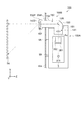
【解決手段】プロジェクター1は、光源および光源から射出された光を変調する光変調装置を備える本体部1Aと、本体部1Aから突出し、本体部1Aから射出された光を投写する投写光学装置1Bと、を備える。投写光学装置1Bは、複数のレンズと、複数のレンズを収納するレンズ筐体5と、を備え、レンズ筐体5は、本体部1Aから射出された光の光軸に交差する第1方向(Z方向)において、本体部1Aから離間する第3収納部53を有し、第3収納部53は、複数のレンズのうち最も光射出側に配置される射出側レンズ431を収納する。
【選択図】図2To provide a projector that allows a user to observe an image in an environment having a more open feeling.
A projector includes a light source and a main body portion that includes a light modulation device that modulates light emitted from the light source, and a projection optical device that projects from the main body portion and projects light emitted from the main body portion. And comprising. The projection optical apparatus 1B includes a plurality of lenses and a lens housing 5 that houses the plurality of lenses. The lens housing 5 intersects the optical axis of the light emitted from the main body 1A (first direction ( In the Z direction), the third storage portion 53 is spaced apart from the main body portion 1A, and the third storage portion 53 stores the exit side lens 431 arranged on the most light exit side among the plurality of lenses.
[Selection] Figure 2
Description
本発明は、プロジェクターに関する。 The present invention relates to a projector.
従来、光源と、光源から射出された光を画像情報に応じて変調する光変調装置と、光変調装置にて変調された光を投写面に投写する投写光学装置と、を備えたプロジェクターが知られている。また、このプロジェクターを支持する装置を用いてホールや会議室等の天井等にプロジェクターを設置してホール内や会議室内の投写面に画像を投写できるように構成されたプロジェクターが提案されている(例えば、特許文献1参照)。 2. Description of the Related Art Conventionally, a projector including a light source, a light modulation device that modulates light emitted from the light source according to image information, and a projection optical device that projects light modulated by the light modulation device onto a projection surface is known. It has been. In addition, there has been proposed a projector configured to install a projector on a ceiling or the like of a hall or a conference room using an apparatus that supports the projector and project an image on a projection surface in the hall or the conference room ( For example, see Patent Document 1).
特許文献1に記載のプロジェクターは、筐体の底面部にL字状の挿入凹部を有する複数の突出部が並設されている。プロジェクターは、この挿入凹部に固定金具の板状部が挿入されて固定金具に支持され、この固定金具を介して天井に吊り下げられる。そして、プロジェクターは、天井の下方に配置された投写面に画像を投写する。
In the projector described in
しかしながら、特許文献1に記載のプロジェクターは、天井に吊り下げられた状態で、投写面が配置されたホール内や会議室内で画像を観察するユーザーに圧迫感を与えることや、室内の美観を損ねる恐れがある。特に、高輝度化や高解像度化の画像の投写のために大型化するプロジェクターにおいては、その圧迫感や美観の損失は顕著なものとなる。
However, the projector described in
本発明は、上述の課題の少なくとも一部を解決するためになされたものであり、以下の形態または適用例として実現することが可能である。 SUMMARY An advantage of some aspects of the invention is to solve at least a part of the problems described above, and the invention can be implemented as the following forms or application examples.
[適用例1]本適用例に係るプロジェクターは、画像を投写面に投写するプロジェクターであって、光源および前記光源から射出された光を変調する光変調装置を備える本体部と、前記本体部から突出し、前記本体部から射出された光を投写する投写光学装置と、を備え、前記投写光学装置は、複数のレンズと、前記複数のレンズを収納するレンズ筐体と、を備え、前記レンズ筐体は、前記本体部から射出された光の光軸に交差する第1方向において、前記本体部から離間する離間部を有し、前記離間部は、前記複数のレンズのうち最も光射出側に配置される射出側レンズを収納することを特徴とする。 Application Example 1 A projector according to this application example is a projector that projects an image on a projection surface, and includes a main body unit including a light source and a light modulation device that modulates light emitted from the light source, and the main body unit. A projection optical device that projects light emitted from the main body, and the projection optical device includes a plurality of lenses and a lens housing that houses the plurality of lenses. The body has a separation portion that is separated from the main body portion in a first direction intersecting the optical axis of the light emitted from the main body portion, and the separation portion is located closest to the light emission side among the plurality of lenses. The exit side lens to be arranged is housed.
この構成によれば、投写光学装置は、射出側レンズを収納する離間部が本体部から離間して配設されている。これによって、本体部と離間部との間に仕切り部材を配置してプロジェクターを設置し、射出側レンズから投写面に画像を投写することができる。例えば、天井や室内の壁、あるいは天井や壁に並設される板状の部材等を仕切り部材として用いることで、仕切り部材によって仕切られた一方の空間(第1空間)に離間部を配置し、他方の空間(第2空間、天井裏や壁の内側等)に本体部を配置することができる。すなわち、プロジェクターは、投写面が配置された第1空間で画像を観察するユーザーに、本体部を視認させずに画像を投写することが可能となる。よって、ユーザーに圧迫感を与えることや、室内(第1空間)の美観の損失を抑えて設置され、より開放感を有する環境でユーザーが画像を観察することができるプロジェクターの提供が可能となる。特に、高輝度化や高解像度化の画像の投写のために大型化するプロジェクターにおいて顕著な効果を奏する。 According to this configuration, in the projection optical apparatus, the separation portion that houses the exit side lens is disposed away from the main body portion. Accordingly, the partition member is disposed between the main body portion and the separation portion, the projector is installed, and an image can be projected from the exit side lens onto the projection surface. For example, by using a ceiling or an indoor wall, or a plate-like member arranged in parallel to the ceiling or wall as a partition member, the separation portion is arranged in one space (first space) partitioned by the partition member. The main body can be arranged in the other space (second space, ceiling, inside wall, etc.). That is, the projector can project an image without allowing the user who observes the image in the first space where the projection surface is arranged to visually recognize the main body. Therefore, it is possible to provide a projector that gives a feeling of pressure to the user and that can be installed with reduced loss of aesthetics in the room (first space) and allows the user to observe images in a more open environment. . In particular, the present invention has a remarkable effect in a projector that increases in size for projecting an image with high brightness or high resolution.
[適用例2]上記適用例に係るプロジェクターにおいて、前記投写光学装置は、前記本体部から射出された光を屈折させる第1光学系と、前記第1光学系から射出された光を前記第1方向側に反射する第1反射部、および前記第1方向側に進行した光を前記本体部が射出する光の方向とは反対側となる第2方向側に反射する第2反射部を有する第2光学系と、前記射出側レンズを有し、前記第2光学系から射出された光を屈折させる第3光学系と、を備え、前記離間部は、前記第3光学系を収納することが好ましい。 Application Example 2 In the projector according to the application example described above, the projection optical device includes a first optical system that refracts light emitted from the main body, and the light emitted from the first optical system. A first reflecting portion that reflects toward the direction side, and a second reflecting portion that reflects the light traveling toward the first direction side toward the second direction side opposite to the direction of the light emitted from the main body portion. A second optical system, and a third optical system that includes the exit-side lens and refracts the light emitted from the second optical system, and the separation unit houses the third optical system. preferable.
この構成によれば、投写光学装置は、上述した光学系を備えているので、本体部から射出された光を屈曲させ、本体部が射出する光の方向とは反対側に配置された投写面に拡大した画像の投写が可能となる。また、本体部と離間部との間に仕切り部材を配置することで、本体部および投写光学装置の一部をユーザーに視認させずに画像の投写が可能となる。
したがって、ユーザーに圧迫感を与えることや、室内(第1空間)の美観の損失を抑えて設置され、本体部が射出する光の方向とは反対側に画像を投写するプロジェクターの提供が可能となる。
According to this configuration, since the projection optical apparatus includes the above-described optical system, the projection surface is arranged on the side opposite to the direction of the light emitted from the main body unit by bending the light emitted from the main body unit. It is possible to project an enlarged image. In addition, by arranging a partition member between the main body and the separation portion, it is possible to project an image without allowing the user to visually recognize a part of the main body and the projection optical device.
Therefore, it is possible to provide a projector that gives a feeling of pressure to the user and that is installed with reduced loss of aesthetics in the room (first space) and projects an image on the side opposite to the direction of light emitted from the main body. Become.
[適用例3]上記適用例に係るプロジェクターにおいて、前記投写光学装置は、前記本体部から射出された光を屈折させる第1光学系と、前記第1光学系から射出された光を前記第1方向側に反射する反射部と、前記射出側レンズを有し、前記反射部で反射した光を屈折させる第2光学系と、を備えることが好ましい。 Application Example 3 In the projector according to the application example described above, the projection optical apparatus includes a first optical system that refracts light emitted from the main body, and light emitted from the first optical system. It is preferable to include a reflecting portion that reflects to the direction side and a second optical system that includes the exit-side lens and refracts light reflected by the reflecting portion.
この構成によれば、投写光学装置は、上述した光学系を備えているので、本体部から射出された光を屈曲させ、本体部が射出する光の方向に交差する方向に配置された投写面に拡大した画像の投写が可能となる。また、本体部と離間部との間に仕切り部材を配置することで、本体部および投写光学装置の一部をユーザーに視認させずに画像の投写が可能となる。
したがって、ユーザーに圧迫感を与えることや、室内(第1空間)の美観の損失を抑えて設置され、本体部が射出する光の方向に交差する方向側に画像を投写するプロジェクターの提供が可能となる。
According to this configuration, since the projection optical apparatus includes the above-described optical system, the projection surface is arranged in a direction that bends the light emitted from the main body and intersects the direction of the light emitted from the main body. It is possible to project an enlarged image. In addition, by arranging a partition member between the main body and the separation portion, it is possible to project an image without allowing the user to visually recognize a part of the main body and the projection optical device.
Therefore, it is possible to provide a projector that gives a feeling of pressure to the user and projects an image on the direction side that intersects the direction of the light emitted from the main unit while suppressing loss of aesthetics in the room (first space). It becomes.
[適用例4]上記適用例に係るプロジェクターにおいて、前記投写光学装置は、前記射出側レンズを含むレンズ群を備え、前記レンズ群は、入射された光を広角化して射出する広角化レンズ群であることが好ましい。 Application Example 4 In the projector according to the application example described above, the projection optical device includes a lens group including the exit side lens, and the lens group is a wide angle lens group that widens and emits incident light. Preferably there is.
この構成によれば、投写面に近い位置から拡大投写するプロジェクターを提供することが可能となる。これによって、投写面に対し、画像を観察するユーザーより近い位置に配置されるプロジェクターを構成することが可能となる。よって、本体部および投写光学装置の一部をユーザーに視認さないことにより、ユーザーがプロジェクターの位置を認識しにくい構成であっても、プロジェクターと投写面との間に例えばユーザーが侵入してプロジェクターからの光が遮られることを回避することが可能となる。よって、ユーザーが画像を観察する位置の自由度を高めたプロジェクターの提供が可能となる。 According to this configuration, it is possible to provide a projector that performs enlarged projection from a position close to the projection surface. Accordingly, it is possible to configure a projector that is disposed at a position closer to the projection plane than the user who observes the image. Therefore, even if the user cannot easily recognize the position of the projector by not viewing the main body and the projection optical device by the user, for example, the user may intrude between the projector and the projection surface. It is possible to avoid the light from being blocked. Therefore, it is possible to provide a projector that increases the degree of freedom of the position where the user observes the image.
[適用例5]上記適用例に係るプロジェクターにおいて、当該プロジェクターは、前記離間部に配置され、受光した光に応じた信号を出力する受光部と、前記受光部の出力に応じて当該プロジェクターの動作を制御する制御部と、を備えることが好ましい。 Application Example 5 In the projector according to the application example described above, the projector is disposed in the separation unit and outputs a signal corresponding to received light, and the operation of the projector according to the output of the light receiving unit. It is preferable to include a control unit that controls
この構成によれば、仕切り部材を用いて、離間部が第1空間に配置され、本体部が第2空間に配置されるように、プロジェクターが設置された場合、受光部は、第1空間に配置される。すなわち、プロジェクターは、本体部が仕切り部材によって隠されるように設置された場合であっても、受光部による光の検出、例えば、ユーザーのリモコン操作による光信号を受信することや、第1空間の明るさの検出等が可能となる。そして、プロジェクターは、上述した制御部を備えているので、例えば、ユーザーのリモコン操作に応じた動作や、第1空間の明るさに応じた画像の投写等が可能となる。よって、ユーザーに圧迫感を与えることを抑えて設置され、使い勝手や画像の視認性を向上させたプロジェクターの提供が可能となる。 According to this configuration, when the projector is installed using the partition member such that the separating portion is disposed in the first space and the main body portion is disposed in the second space, the light receiving portion is disposed in the first space. Be placed. That is, even when the projector is installed such that the main body is hidden by the partition member, the light detection by the light receiving unit, for example, receiving a light signal by a user's remote control operation, Brightness can be detected. Since the projector includes the above-described control unit, for example, an operation according to a user's remote control operation, an image projection according to the brightness of the first space, and the like can be performed. Therefore, it is possible to provide a projector that is installed while suppressing the user's feeling of pressure and has improved usability and image visibility.
(第1実施形態)
以下、本実施形態に係るプロジェクターについて、図面を参照して説明する。
本実施形態のプロジェクターは、光源から射出された光を画像情報に応じて変調し、変調した光をスクリーン等の投写面に拡大投写する。また、本実施形態のプロジェクターは、机上等に載置された状態や、天井や壁部に支持具を介して設置される状態が可能に構成されている。
(First embodiment)
Hereinafter, the projector according to the present embodiment will be described with reference to the drawings.
The projector according to the present embodiment modulates light emitted from a light source according to image information, and enlarges and projects the modulated light onto a projection surface such as a screen. In addition, the projector according to the present embodiment is configured to be able to be placed on a desk or the like, or installed on a ceiling or a wall through a support tool.
〔プロジェクターの主な構成〕
図1は、本実施形態のプロジェクター1の主な構成を説明するための模式図である。また、図1は、プロジェクター1の使用形態の一例を示す模式図であり、机上Taに載置された状態(据え置き状態)を示す図である。図2は、プロジェクター1の他の使用形態の一例を示す模式図であり、支持具Mtを介して天井Ceに設置された状態(天吊り状態)を示す図である。
プロジェクター1は、図1に示すように、光学ユニット3を有する本体部1A、および本体部1Aから突出する投写光学装置1Bを備えている。
[Main components of the projector]
FIG. 1 is a schematic diagram for explaining a main configuration of a
As shown in FIG. 1, the
本体部1Aは、後で詳細に説明するが、光源311および光変調装置351等を備え、光源311から射出された光を画像情報に応じて変調し、投写光学装置1Bに射出する。
投写光学装置1Bは、後で詳細に説明するが、複数のレンズを備え、本体部1Aから射集された光をスクリーン等の投写面Sc(図2参照)に投写する。
As will be described in detail later, the
As will be described in detail later, the projection
プロジェクター1は、図2に示すように、天吊り状態において、据え置き状態の姿勢(据え置き姿勢)から上下が反転された姿勢(天吊り姿勢)となる。そして、プロジェクター1は、天吊り状態において、天井Ceに並設された板状の仕切り部材Paが用いられることによって、本体部1Aおよび投写光学装置1Bの一部を隠すことができるように構成されている。なお、説明の便宜上、本体部1Aから射出された光の方向を+X方向(前方)、X方向に直交し、天吊り姿勢のプロジェクター1において、鉛直方向の上方を+Z方向、投写面Scに対向する側から見たプロジェクター1の右方を+Y方向として記載する。
As shown in FIG. 2, the
〔本体部の構成〕
図3は、本体部1Aの主な構成を示す模式図である。
本体部1Aは、図3に示すように、外装筐体2、外装筐体2内に収納される制御部6、光学ユニット3、および投写光学装置1Bに配置されるリモコン受光部7を備えている。また、図示は省略するが、本体部1Aは、光学ユニット3の光源装置31や制御部6等に電力を供給する電源装置、および光学ユニット3や電源装置を冷却する冷却装置を備える。
[Configuration of the main unit]
FIG. 3 is a schematic diagram showing a main configuration of the
As shown in FIG. 3, the
外装筐体2は、合成樹脂製の部材が複数組み合わされて構成されており、図1、図2に示すように、前側(+X側)を形成する前面部2F、後側(−X側)を形成する背面部2B、天吊り姿勢において、上側(+Z側)、下側(−Z側)をそれぞれ形成する上面部2U、下面部2D等を有している。
The exterior housing 2 is configured by combining a plurality of synthetic resin members. As shown in FIGS. 1 and 2, the
前面部2Fには、図1に示すように、窪み部21が設けられている。窪み部21には、上下方向の略中央に、前後方向に貫通する貫通孔(図示省略)が形成されている。投写光学装置1Bは、一部(後述する第2収納部52の一部)が窪み部21に挿入され、一部(後述する第1収納部51の円筒部511、図1参照)が貫通孔に挿通されて、本体部1Aに装着される。
As shown in FIG. 1, the front surface portion 2 </ b> F is provided with a
上面部2Uには、据え置き状態(図1参照)で机上等に当接し、プロジェクター1を支持する脚部2Uf、および天吊り状態(図2参照)で支持具Mtが結合される結合部(図示省略)が設けられている。なお、図示は省略するが、外装筐体2には、外気を取り込む吸気口や、外装筐体2内部の温まった空気を外部に排気する排気口等が設けられている。
The
制御部6は、CPU(Central Processing Unit)やROM(Read Only Memory)、RAM(Random Access Memory)等を備え、コンピューターとして機能するものであり、プロジェクター1の動作の制御、例えば、画像の投写に関わる制御等を行う。
The control unit 6 includes a central processing unit (CPU), a read only memory (ROM), a random access memory (RAM), and the like, and functions as a computer. The control unit 6 controls the operation of the
光学ユニット3は、制御部6による制御の下、光源装置31から射出された光を光学的に処理し、投写光学装置1Bに射出する。
光学ユニット3は、図3に示すように、光源装置31に加え、インテグレーター照明光学系32、色分離光学系33、リレー光学系34、光学装置35、およびこれらの光学部品を光路上の所定位置に配置する光学部品用筐体37を備える。
The
As shown in FIG. 3, in addition to the
光源装置31は、超高圧水銀ランプやメタルハライドランプ等からなる放電型の光源311、およびリフレクター312等を備える。光源装置31は、光源311から射出された光をリフレクター312にて反射し、インテグレーター照明光学系32に向けて射出する。
The
インテグレーター照明光学系32は、第1レンズアレイ321、第2レンズアレイ322、偏光変換素子323、および重畳レンズ324を備える。
第1レンズアレイ321は、小レンズがマトリックス状に配列された構成を有しており、光源装置31から射出された光を複数の部分光に分割する。第2レンズアレイ322は、第1レンズアレイ321と略同様の構成を有しており、重畳レンズ324と共に、部分光を光変調装置351の表面に略重畳させる。偏光変換素子323は、第2レンズアレイ322から射出されたランダム光を光変調装置で利用可能な略1種類の偏光光に揃える機能を有している。
The integrator illumination
The
色分離光学系33は、2枚のダイクロイックミラー331,332、および反射ミラー333を備え、インテグレーター照明光学系32から射出された光を赤色光(以下「R光」という)、緑色光(以下「G光」という)、青色光(以下「B光」という)の3色の色光に分離する機能を有する。
The color separation optical system 33 includes two
リレー光学系34は、入射側レンズ341、リレーレンズ343、および反射ミラー342,344を備え、色分離光学系33で分離されたR光をR光用の光変調装置351まで導く機能を有する。なお、光学ユニット3は、リレー光学系34がR光を導く構成としているが、これに限らず、例えば、B光を導く構成としてもよい。
The relay
光学装置35は、各色光用に設けられた光変調装置351(R光用の光変調装置を351R、G光用の光変調装置を351G、B光用の光変調装置を351Bとする)、および色合成光学装置としてのクロスダイクロイックプリズム352を備える。
光変調装置351は、透過型の液晶パネル、液晶パネルの光入射側に配置された入射側偏光板、および液晶パネルの光射出側に配置された射出側偏光板を備える。
光変調装置351は、図示しない複数の微小画素がマトリックス状に形成された矩形状の画像形成領域を有する。各画素が画像情報に応じた光透過率に設定され、画像形成領域内には、表示画像が形成される。そして、各色光は、光変調装置351にて変調された後、クロスダイクロイックプリズム352に射出される。
The
The
The
クロスダイクロイックプリズム352は、4つの直角プリズムを貼り合わせた平面視略正方形状をなし、直角プリズム同士を貼り合わせた界面には、2つの誘電体多層膜が形成されている。クロスダイクロイックプリズム352は、誘電体多層膜が光変調装置351R,351Bにて変調されたR光およびB光を反射し、光変調装置351Gにて変調されたG光を透過して、3色の変調光を合成する。
The cross
リモコン受光部7は、受光部に相当し、プロジェクター1を遠隔操作するためのリモートコントローラー(リモコン、図示省略)から発せられる光信号(赤外線による操作信号)を受光し、受光した光に応じた信号を制御部6に出力する。
リモコン受光部7は、図1、図2に示すように、投写光学装置1Bの後述するレンズ筐体5内に配置され、図示しないケーブルを介して制御部6に接続されている。制御部6は、リモコン受光部7の出力に応じてプロジェクター1の動作を制御する。
The remote control
As shown in FIGS. 1 and 2, the remote control
〔投写光学装置の構成〕
投写光学装置1Bは、本体部1Aに着脱可能に構成され、クロスダイクロイックプリズム352にて合成された光を、プロジェクター1の後側(−X側)に配置された投写面Scに拡大投写する。
投写光学装置1Bは、図1、図2に示すように、第1光学系41、第2光学系42、および第3光学系43と、これらの光学系を収納するレンズ筐体5とを備え、概略U字状に形成されている。
投写光学装置1Bは、図1に示すように、クロスダイクロイックプリズム352から射出された光が第1光学系41に入射し、第3光学系43が外装筐体2(下面部2D)の−Z側に位置するように配置される。
[Configuration of projection optical device]
The projection
As shown in FIGS. 1 and 2, the projection
As shown in FIG. 1, in the projection
第1光学系41は、複数のレンズを有し(図1では1つのレンズを示す)、クロスダイクロイックプリズム352から射出された光を屈折させる。
第2光学系42は、第1反射部としての反射ミラー421、および第2反射部としての反射ミラー422を有している。
反射ミラー421は、第1光学系41の前方(+X側)に配置され、第1光学系41から射出された光を−Z側に反射する。−Z方向は、本体部1Aから射出された光の光軸Axに交差する方向(本実施形態では、直交する方向)であり、第1方向に相当する。
The first
The second
The
反射ミラー422は、−Z側に進行した光を本体部1Aが射出する光の方向(+X方向)とは反対側となる−X側に反射する。−X方向は、第2方向に相当する。なお、第2光学系42は、反射ミラー421,422に加え、レンズを有する構成であってもよい。
The
第3光学系43は、複数のレンズを有し(図1では1つのレンズ(後述する射出側レンズ431)を示す)、第2光学系42から射出された光を屈折させる。第3光学系43は、複数のレンズのうち最も光射出側に配置される射出側レンズ431を備える。そして、第3光学系43は、射出側レンズ431を含む広角化レンズ群を備える。広角化レンズ群は、第2光学系42から射出された光を広角化し、X方向に直交する投写面Sc(図2参照)に対して−Z向きにあおり投写を行う。すなわち、投写光学装置1Bは、図2に示すように、プロジェクター1の後側(−X側)で上下方向(Z方向)において本体部1Aの下方(−Z方向)に配置された投写面Scに画像を投写する。また、投写光学装置1Bは、投写面Scに近い位置での拡大投写が可能で、プロジェクター1は、投写光学装置1Bが装着されることで、短焦点プロジェクターとして機能する。
The third
レンズ筐体5は、図1に示すように、第1光学系41を収納する第1収納部51、第2光学系42を収納する第2収納部52、および第3光学系43を収納する第3収納部53を有している。
第1収納部51は、図1に示すように、光入射側に円筒部511を有し、この円筒部511が前述した窪み部21の貫通孔から挿入される。そして、この円筒部511の外周には、円周方向に断続的に設けられた複数の突起(図示省略)が形成されている。投写光学装置1Bは、この複数の突起が本体部1Aに設けられた着脱機構(図示省略)に係合して本体部1Aに装着される。また、投写光学装置1Bは、着脱機構が操作されて、複数の突起と着脱機構との係合が解除されて本体部1Aからの取り外しが可能となる。
As shown in FIG. 1, the
As shown in FIG. 1, the
第2収納部52は、図1に示すように、Z方向に沿って延出し、反射ミラー421,422それぞれの反射面とは反対側に設けられた傾斜壁部521,522を有している。
反射ミラー421の外側に設けられた傾斜壁部521は、図1に示すように、机上Taから遠ざかる程、第1光学系41から遠ざかるように傾斜している。反射ミラー422の外側に設けられた傾斜壁部522は、図1に示すように、机上Taから遠ざかる程、第3光学系43に近づくように傾斜している。
As shown in FIG. 1, the
As shown in FIG. 1, the
傾斜壁部522には、開口部が設けられており、この開口部は、フィルター部材7Fによって閉塞されている。フィルター部材7Fは、赤外線を透過し、可視光をカットする板状の部材であり、リモコン受光部7は、このフィルター部材7Fの内側に配置されている。すなわち、リモコン受光部7は、リモコンから発せられ、フィルター部材7Fを透過した赤外線による光信号を受信する。また、リモコン受光部7は、天吊り状態(図2参照)で指向特性の中心軸が下方斜め(+X方向と−Z方向との間)に沿うように配置されている。
The
第3収納部53は、反射ミラー422の−X側に設けられ、X方向に沿って延出している。第3収納部53および第2収納部52の反射ミラー422を収納する部位(以下、「先端側収納部5P」という)は、Z方向、すなわち第1方向において、本体部1Aと離間して配置され、離間部に相当する。リモコン受光部7は、先端側収納部5P内に配置されている。ここで、先端側収納部5Pと本体部1Aとが離間しているとは、図2に示すように、先端側収納部5Pと本体部1Aとの間に板状の仕切り部材Paが配置可能な距離で離間していることをいう。
The
このように、投写光学装置1Bは、概略U字状に形成され、Z方向において、先端側収納部5Pが本体部1Aと離間して本体部1Aに装着される。
そして、プロジェクター1は、図2に示すように、天井Ceに設置され、先端側収納部5Pと本体部1Aとの間に仕切り部材Paが配置された状態では、先端側収納部5Pが仕切り部材Paの下方の空間(第1空間10S)に位置し、本体部1Aおよび第1収納部51と、第2収納部52の一部とが仕切り部材Paの上方の空間(第2空間20S)に位置して配置される。
第1空間10Sには、投写面Scが配置されるので、ユーザー(投写面Scに投写される画像の観察者)も第1空間10Sで画像を観察する。すなわち、プロジェクター1は、第2空間20Sに位置する本体部1A等がユーザーから見えないように配置される。
As described above, the projection
As shown in FIG. 2, the
Since the projection plane Sc is arranged in the
なお、仕切り部材Paは、図2に示すように、第2収納部52の+X側に位置する第1部材Pa1、および第2収納部52の−X側に位置する第2部材Pa2を有している。そして、第1部材Pa1と第2部材Pa2との間には第2収納部52が配置可能な開口部Pahが設けられている。また、第2部材Pa2は、天井Ceに沿う方向にスライド可能に構成されており、プロジェクター1の天井Ceへの取り付け、取り外しは、この第2部材Pa2がスライドされて行われる。
As shown in FIG. 2, the partition member Pa includes a first member Pa <b> 1 located on the + X side of the
また、リモコン受光部7は、先端側収納部5Pに配置されているので、第1空間10Sに位置する。さらに、リモコン受光部7は、傾斜壁部522内で指向特性の中心軸が下方斜めに沿うように配置されているので、第3収納部53の下方や、投写面Scから離れた位置で発せられるリモコンの光信号を受信することができる。
Moreover, since the remote control light-receiving
以上説明したように、本実施形態によれば、以下の効果を得ることができる。
(1)投写光学装置1Bは、射出側レンズ431を収納する先端側収納部5P(離間部)が本体部1Aから離間して配設されている。これによって、天吊り状態で仕切り部材Paを用いることによって、本体部1Aおよび投写光学装置1Bの一部を隠すことができる。よって、ユーザーに圧迫感を与えることや、室内(第1空間10S)の美観の損失を抑えて設置され、より開放感を有する環境でユーザーが画像を観察することができるプロジェクター1の提供が可能となる。特に、高輝度化や高解像度化の画像の投写のために大型化するプロジェクターにおいて顕著な効果を奏する。
As described above, according to the present embodiment, the following effects can be obtained.
(1) In the projection
(2)投写光学装置1Bは、概略U字状に配置された第1光学系41〜第3光学系43を備えているので、本体部1Aから射出された光を屈曲させ、本体部1Aが射出する光の方向とは反対側に配置された投写面Scに拡大した画像の投写が可能となる。
また、投写光学装置1Bは、第3光学系43が入射する光を広角化させるレンズを有しているので、投写面Scに近い位置からの拡大投写が可能となる。
また、投写面Scに対し、画像を観察するユーザーより近い位置に配置されるプロジェクター1を構成することが可能となる。よって、本体部1Aおよび投写光学装置1Bの一部をユーザーに視認さないことにより、ユーザーがプロジェクター1の位置を認識しにくい構成であっても、プロジェクター1と投写面Scとの間にユーザーが侵入してプロジェクター1からの光が遮られることを回避することが可能となる。よって、ユーザーが画像を観察する位置の自由度を高めたプロジェクターの提供が可能となる。
また、プロジェクター1は、投写光学装置1Bが概略U字状に形成されているので、前後方向(X方向)の小型化が可能となる。
(2) Since the projection
In addition, since the projection
In addition, it is possible to configure the
Further, since the projection
(3)プロジェクター1は、外装筐体2の窪み部21に第2収納部52の一部が挿入されるように構成されている。これによって、前後方向(X方向)におけるプロジェクター1のさらなる小型化が可能となる。また、本体部1Aと投写光学装置1Bとが一体化されたプロジェクター1として視認させることが可能なので、プロジェクター1の外観の向上が可能となる。
(3) The
(4)プロジェクター1は、リモコン受光部7が先端側収納部5P内に配置されている。これによって、本体部1Aが仕切り部材Paによって隠されるように設置された場合であっても、ユーザーのリモコン操作による光信号を受信することができる。よって、ユーザーに圧迫感を与えることを抑えて設置され、使い勝手が良好なプロジェクター1の提供が可能となる。
さらに、リモコン受光部7は、天吊り状態において、指向特性の中心軸が下方斜めに沿うように配置されているので、ユーザーの様々な位置からのリモコン操作による光信号を受光することが可能となる。
(4) In the
Furthermore, since the remote control
(第2実施形態)
以下、第2実施形態に係るプロジェクター100について、図面を参照して説明する。以下の説明では、第1実施形態と同様の構成要素には、同一符号を付し、その詳細な説明は省略または簡略化する。
図4は、本実施形態のプロジェクター100の主な構成を説明するための模式図であり、プロジェクター100の使用形態の一例を示す図である。具体的に、図4は、支持具Mtを介して室内の壁部Waに支持された状態(壁掛け状態)を示す図である。
本実施形態のプロジェクター100は、図4に示すように、第1実施形態の投写光学装置1Bとは異なる投写光学装置100Bを備える。また、本実施形態のプロジェクター100の本体部100Aは、受光部としてリモコン受光部7(図4では図示省略)に加え、撮像部107をさらに備えている。
(Second Embodiment)
Hereinafter, the
FIG. 4 is a schematic diagram for explaining a main configuration of the
As shown in FIG. 4, the
本実施形態のプロジェクター100は、図4に示すように、室内の壁部Waの裏側に本体部100Aが固定され、壁部Waに設けられた開口部Wahから投写光学装置100Bの一部が突出して設置できるように構成されている。そして、プロジェクター100は、壁部Waに対向する位置に配置された投写面Scに画像を投写する。なお、説明の便宜上、X方向、Y方向およびZ方向については、本実施形態の本体部100Aと第1実施形態の本体部1Aとが対応するように記載する。すわなち、本体部100Aから射出された光の方向を+X方向、壁部Waから投写面Scに向かう方向を−Z方向、投写面Scに対向する側から見たプロジェクター1の右側を+Y側として記載する。
As shown in FIG. 4, in the
投写光学装置100Bは、図4に示すように、第1光学系141、反射部としての反射ミラー14R、および第2光学系142と、これらの光学系を収納するレンズ筐体150とを備える。
第1光学系141は、複数のレンズを有し(図4では1つのレンズを示す)、クロスダイクロイックプリズム352から射出された光を屈折させる。
As shown in FIG. 4, the projection
The first
反射ミラー14Rは、第1光学系141の+X側に配置され、第1光学系141から射出された光を−Z側に反射する。−Z方向は、第1実施形態と同様に、本体部100Aから射出された光の光軸Axに交差する方向(本実施形態では、直交する方向)であり、第1方向に相当する。
The
第2光学系142は、複数のレンズ(図4では1つのレンズ(射出側レンズ1422)を示す)を備え、反射ミラー14Rで反射した光を屈折させる。
第2光学系142は、複数のレンズのうち最も光射出側に配置される射出側レンズ1422を備え、反射ミラー14Rで反射された光を広角化して−X向きにあおり投写を行う。すなわち、投写光学装置100Bは、図4に示すように、プロジェクター100の−Z側に配置され、Z方向に直交する投写面Scに画像を投写する。また、投写光学装置100Bは、投写面Scに近い位置での拡大投写が可能で、プロジェクター100は、投写光学装置100Bが装着されることで、短焦点プロジェクターとして機能する。
The second optical system 142 includes a plurality of lenses (showing one lens (exit-side lens 1422) in FIG. 4), and refracts the light reflected by the reflecting
The second optical system 142 includes an exit-
レンズ筐体150は、図4に示すように、第1光学系141を収納する第1収納部151と、反射ミラー14Rおよび第2光学系142を収納する第2収納部152とを有している。
第2収納部152は、図4に示すように、Z方向に沿って延出しており、射出側レンズ1422を収納する先端側収納部150Pを有している。
先端側収納部150Pは、Z方向、すなわち第1方向において、本体部100Aと離間して配置され、離間部に相当する。
As shown in FIG. 4, the
As shown in FIG. 4, the second storage portion 152 extends along the Z direction and has a distal end
The distal end
撮像部107は、例えば、CCD(Charge Coupled Device)やCMOS(Complementary Metal Oxide Semiconductor)等の撮像素子(図示省略)を備え、図4に示すように、先端側収納部150P内の射出側レンズ1422の−X側に配置される。
撮像部107は、被写体としての投写面Scを撮影し、撮影した画像に応じた情報を制御部6に出力する。制御部6は、撮像部107の出力に基づいて、画像の調整や変更等を行う。例えば、撮像部107は、投写面Scに投写された台形状に歪んだ画像の撮影や、投写面Sc上で操作された指示具(例えば、電子ペン等)から発せられる赤外光を検出する。制御部6は、撮像部107の出力に基づいて、台形状に歪んだ画像の調整や、画像情報に指示具の軌跡が重畳された重畳画像を投写面Scに投写させる指示等を行う。
なお、図4では図示しないリモコン受光部7は、先端側収納部150P内に配置されている。
The
The
Note that the remote control light receiving unit 7 (not shown in FIG. 4) is disposed in the distal end
このように、投写光学装置100Bは、概略L字状に形成され、射出側レンズ1422および撮像部107を収納する先端側収納部150Pが、Z方向において、本体部100Aと離間して本体部100Aに装着される。
そして、プロジェクター100は、図4に示すように、本体部100Aが支持具Mtを介して壁部Waの裏側に固定され、開口部Wahから先端側収納部150Pが壁部Waの表側に突出して配置される。
壁部Waの表側の空間には、投写面Scが配置されるので、プロジェクター100は、ユーザー(投写面Scに投写される画像の観察者)から本体部100Aが見えないように配置される。
撮像部107は、先端側収納部150P内に配置されているので、プロジェクター100が壁部Waに設置された状態でも、投写面Scの撮影が可能となる。
As described above, the projection
In the
Since the projection surface Sc is disposed in the space on the front side of the wall Wa, the
Since the
以上説明したように、本実施形態によれば、以下の効果を得ることができる。
(1)投写光学装置100Bは、射出側レンズ1422を収納する先端側収納部150P(離間部)が本体部100Aから離間して配設されている。これによって、壁掛け状態において、本体部100Aおよび投写光学装置100Bの一部を隠すことができる。よって、ユーザーに圧迫感を与えることや、室内の美観の損失を抑えて設置され、より開放感を有する環境でユーザーが画像を観察することができるプロジェクター100の提供が可能となる。
As described above, according to the present embodiment, the following effects can be obtained.
(1) In the projection
(2)投写光学装置100Bは、概略L字状に配置された光学系を備えているので、本体部100Aから射出された光を屈曲させ、本体部100Aが射出する光の方向に交差する方向に配置された投写面Scに拡大した画像の投写が可能となる。
また、投写光学装置100Bは、第2光学系142が入射する光を広角化させるレンズを有しているので、投写面Scに近い位置からの拡大投写が可能となる。
(2) Since the projection
Further, since the projection
(3)プロジェクター100は、先端側収納部150P内に配置された撮像部107を備えているので、本体部100Aが壁部Waによって隠されるように設置された場合であっても、投写面Scを撮影し、この撮影した情報に基づいて、画像の調整や変更等を行うことができる。
(3) Since the
(変形例)
なお、前記実施形態は、以下のように変更してもよい。
第1実施形態では、プロジェクター1の天吊り状態として本体部1Aが天井Ceの表面に取り付けられる態様を例示したが、本体部1Aが天井Ceの裏面に取り付けられ、天井Ceが先端側収納部5Pと本体部1Aとの間に配置される仕切り部材として構成される態様であってもよい。
また、第1実施形態のプロジェクター1が壁部Waに設置される態様であってもよい。この構成の場合、壁部Waや壁部Waに並設される仕切り部材を用いて本体部1Aを隠し、床や床に並設される部材を投写面とする投写が可能となる。
(Modification)
In addition, you may change the said embodiment as follows.
In the first embodiment, the mode in which the
Moreover, the aspect by which the
第2実施形態では、プロジェクター100の壁掛け状態として本体部100Aが壁部Waの裏面に取り付けられる態様を例示したが、本体部100Aが壁部Waの表面に取り付けられ、先端側収納部150Pと本体部100Aとの間に仕切り部材を配置する態様であってもよい。
また、第2実施形態のプロジェクター100が天井Ceに設置される態様であってもよい。この構成の場合、天井Ceや天井Ceに並設される仕切り部材を用いて本体部100Aを隠し、床や床に並設される部材を投写面とする投写が可能となる。
In the second embodiment, an example in which the
Further, the
プロジェクター1,100を据え置き姿勢で配置し、床面や床面に並設される部材を仕切り部材とし本体部1A,100Aを隠す態様であってもよい。
また、前述したプロジェクター1,100の姿勢以外の姿勢でプロジェクター1,100を配置し、仕切り部材を用いて本体部1A,100Aを隠す態様であってもよい。
The
Moreover, the aspect which arrange | positions the projector 1100 with attitude | positions other than the attitude | position of the projector 1100 mentioned above, and hides the main-
第1実施形態のプロジェクター1が受光部としての撮像部107を備える構成であってもよい。
前記実施形態では、受光部としてリモコン受光部7、撮像部107を例示したが、受光する光に応じた信号を出力する素子であればこれに限らない。例えば、受光部として他に照度を検出する照度センサー等を例示することができる。この構成によれば、プロジェクター1,100は、室内(第1空間10S)の明るさに応じた画像の投写が可能となるので、ユーザーにより鮮明な画像を提供することが可能となる。
The
In the above embodiment, the remote control
前記実施形態のプロジェクター1は、光変調装置351として透過型の液晶パネルを用いているが、反射型の液晶パネルを利用したものであってもよい。
また、前記実施形態の光変調装置351は、R光、G光、およびB光に対応する3つの光変調装置を用いるいわゆる3板方式を採用しているが、これに限らず、単板方式を採用してもよく、あるいは、2つまたは4つ以上の光変調装置を備えるプロジェクターにも適用できる。
また、光変調装置としてマイクロミラー型の光変調装置、例えば、DMD(Digital Micromirror Device)等を利用したものであってもよい。
In the
In addition, the
Further, a micromirror type light modulation device such as a DMD (Digital Micromirror Device) may be used as the light modulation device.
前記実施形態の光源装置31は、放電型の光源311を採用しているが、その他の方式の光源や発光ダイオード、レーザー等の固体光源で構成してもよい。
The
1,100…プロジェクター、1A,100A…本体部、1B,100B…投写光学装置、2…外装筐体、3…光学ユニット、5,150…レンズ筐体、5P,150P…先端側収納部(離間部)、6…制御部、7…リモコン受光部(受光部)、31…光源装置、41,141…第1光学系、42,142…第2光学系、43…第3光学系、107…撮像部(受光部)、311…光源、351,351B,351G,351R…光変調装置、421…反射ミラー(第1反射部)、422…反射ミラー(第2反射部)、431,1422…射出側レンズ、14R…反射ミラー(反射部)、Ax…光軸、Sc…投写面。 DESCRIPTION OF SYMBOLS 1,100 ... Projector, 1A, 100A ... Main-body part, 1B, 100B ... Projection optical apparatus, 2 ... Exterior housing, 3 ... Optical unit, 5,150 ... Lens housing, 5P, 150P ... Front end side storage part (separation) Part), 6 ... control part, 7 ... remote control light receiving part (light receiving part), 31 ... light source device, 41, 141 ... first optical system, 42, 142 ... second optical system, 43 ... third optical system, 107 ... Imaging unit (light receiving unit), 311... Light source, 351, 351B, 351G, 351R... Light modulation device, 421... Reflection mirror (first reflection unit), 422 ... reflection mirror (second reflection unit), 431, 1422. Side lens, 14R: reflection mirror (reflection part), Ax: optical axis, Sc: projection plane.
Claims (5)
光源および前記光源から射出された光を変調する光変調装置を備える本体部と、
前記本体部から突出し、前記本体部から射出された光を投写する投写光学装置と、
を備え、
前記投写光学装置は、
複数のレンズと、
前記複数のレンズを収納するレンズ筐体と、
を備え、
前記レンズ筐体は、前記本体部から射出された光の光軸に交差する第1方向において、前記本体部から離間する離間部を有し、
前記離間部は、前記複数のレンズのうち最も光射出側に配置される射出側レンズを収納することを特徴とするプロジェクター。 A projector that projects an image onto a projection surface,
A main body comprising a light source and a light modulation device that modulates light emitted from the light source;
A projection optical device that projects from the main body and projects light emitted from the main body;
With
The projection optical device includes:
Multiple lenses,
A lens housing that houses the plurality of lenses;
With
The lens housing has a separation portion that is separated from the main body portion in a first direction intersecting an optical axis of light emitted from the main body portion,
The said separation | spacing part accommodates the emission side lens arrange | positioned at the light emission side most among these lenses.
前記投写光学装置は、
前記本体部から射出された光を屈折させる第1光学系と、
前記第1光学系から射出された光を前記第1方向側に反射する第1反射部、および前記第1方向側に進行した光を前記本体部が射出する光の方向とは反対側となる第2方向側に反射する第2反射部を有する第2光学系と、
前記射出側レンズを有し、前記第2光学系から射出された光を屈折させる第3光学系と、
を備え、
前記離間部は、前記第3光学系を収納することを特徴とするプロジェクター。 The projector according to claim 1,
The projection optical device includes:
A first optical system for refracting light emitted from the main body,
A first reflecting portion that reflects light emitted from the first optical system toward the first direction side, and a light that travels toward the first direction side is opposite to the direction of light emitted from the main body portion. A second optical system having a second reflecting portion that reflects toward the second direction;
A third optical system having the exit side lens and refracting light emitted from the second optical system;
With
The projector is characterized in that the separation unit houses the third optical system.
前記投写光学装置は、
前記本体部から射出された光を屈折させる第1光学系と、
前記第1光学系から射出された光を前記第1方向側に反射する反射部と、
前記射出側レンズを有し、前記反射部で反射した光を屈折させる第2光学系と、
を備えることを特徴とするプロジェクター。 The projector according to claim 1,
The projection optical device includes:
A first optical system for refracting light emitted from the main body,
A reflecting portion that reflects the light emitted from the first optical system toward the first direction;
A second optical system having the exit lens and refracting the light reflected by the reflecting portion;
A projector comprising:
前記投写光学装置は、前記射出側レンズを含むレンズ群を備え、
前記レンズ群は、入射された光を広角化して射出する広角化レンズ群であることを特徴とするプロジェクター。 It is a projector as described in any one of Claims 1-3, Comprising:
The projection optical apparatus includes a lens group including the exit side lens,
The projector is characterized in that the lens group is a wide-angle lens group that widens and emits incident light.
当該プロジェクターは、
前記離間部に配置され、受光した光に応じた信号を出力する受光部と、
前記受光部の出力に応じて当該プロジェクターの動作を制御する制御部と、
を備えることを特徴とするプロジェクター。 It is a projector as described in any one of Claims 1-4, Comprising:
The projector is
A light receiving portion that is disposed in the separation portion and outputs a signal corresponding to the received light;
A control unit for controlling the operation of the projector according to the output of the light receiving unit;
A projector comprising:
Priority Applications (1)
| Application Number | Priority Date | Filing Date | Title |
|---|---|---|---|
| JP2016101155A JP2017207688A (en) | 2016-05-20 | 2016-05-20 | projector |
Applications Claiming Priority (1)
| Application Number | Priority Date | Filing Date | Title |
|---|---|---|---|
| JP2016101155A JP2017207688A (en) | 2016-05-20 | 2016-05-20 | projector |
Publications (1)
| Publication Number | Publication Date |
|---|---|
| JP2017207688A true JP2017207688A (en) | 2017-11-24 |
Family
ID=60417077
Family Applications (1)
| Application Number | Title | Priority Date | Filing Date |
|---|---|---|---|
| JP2016101155A Pending JP2017207688A (en) | 2016-05-20 | 2016-05-20 | projector |
Country Status (1)
| Country | Link |
|---|---|
| JP (1) | JP2017207688A (en) |
Cited By (5)
| Publication number | Priority date | Publication date | Assignee | Title |
|---|---|---|---|---|
| CN112740104A (en) * | 2018-09-21 | 2021-04-30 | 富士胶片株式会社 | Projection device and projection lens |
| CN113534581A (en) * | 2020-04-22 | 2021-10-22 | 精工爱普生株式会社 | Projection optics and projectors |
| WO2022009665A1 (en) * | 2020-07-07 | 2022-01-13 | ソニーセミコンダクタソリューションズ株式会社 | Image display device and control method |
| JP2023094241A (en) * | 2021-12-23 | 2023-07-05 | 富士フイルム株式会社 | Projection lens and projection device |
| WO2024224924A1 (en) * | 2023-04-24 | 2024-10-31 | 富士フイルム株式会社 | Projection device, control method, and control program |
-
2016
- 2016-05-20 JP JP2016101155A patent/JP2017207688A/en active Pending
Cited By (9)
| Publication number | Priority date | Publication date | Assignee | Title |
|---|---|---|---|---|
| CN112740104A (en) * | 2018-09-21 | 2021-04-30 | 富士胶片株式会社 | Projection device and projection lens |
| US11698576B2 (en) | 2018-09-21 | 2023-07-11 | Fujifilm Corporation | Projection device having rotation lock mechanism and projection lens having rotation lock mechanism |
| CN113534581A (en) * | 2020-04-22 | 2021-10-22 | 精工爱普生株式会社 | Projection optics and projectors |
| JP2021173814A (en) * | 2020-04-22 | 2021-11-01 | セイコーエプソン株式会社 | Projection optics and projectors |
| JP7476643B2 (en) | 2020-04-22 | 2024-05-01 | セイコーエプソン株式会社 | Projection optical device and projector |
| WO2022009665A1 (en) * | 2020-07-07 | 2022-01-13 | ソニーセミコンダクタソリューションズ株式会社 | Image display device and control method |
| JP2023094241A (en) * | 2021-12-23 | 2023-07-05 | 富士フイルム株式会社 | Projection lens and projection device |
| JP7761473B2 (en) | 2021-12-23 | 2025-10-28 | 富士フイルム株式会社 | Projection lens and projection device |
| WO2024224924A1 (en) * | 2023-04-24 | 2024-10-31 | 富士フイルム株式会社 | Projection device, control method, and control program |
Similar Documents
| Publication | Publication Date | Title |
|---|---|---|
| US9667924B2 (en) | Projection-type image display device | |
| US8585217B2 (en) | Bidirectional projector | |
| JP6628940B2 (en) | projector | |
| WO2014171134A1 (en) | Projection-type video display apparatus | |
| JP2017207688A (en) | projector | |
| JP6921231B2 (en) | projector | |
| US20220308695A1 (en) | Detection apparatus, detection method, and spatial projection apparatus | |
| US9632400B2 (en) | Projector having an exterior enclosure and a receiver disposed in a swelling portion of the exterior enclosure | |
| US11323672B2 (en) | Control method for projector and projector | |
| US12265235B2 (en) | Detection apparatus, detection method, and spatial projection apparatus | |
| US20050254020A1 (en) | Optical engine apparatus | |
| CN111586378A (en) | Projector and control method of projector | |
| US11531255B2 (en) | Projector, projection optical device, and method of controlling projector | |
| CN100403785C (en) | Projection system and projector | |
| JP4650256B2 (en) | Information presentation system | |
| JP2009229509A (en) | Optical device and optical system | |
| JP2011227300A (en) | Projection type video display device | |
| JP2009210855A (en) | Housing for optical component and projector | |
| US20160119614A1 (en) | Display apparatus, display control method and computer readable recording medium recording program thereon | |
| TW201826781A (en) | Projecting unit and projecting device using the same | |
| US11843902B2 (en) | Image forming medium changing device, spatial projection apparatus, spatial projection system, and spatial projection method | |
| JP7533143B2 (en) | Projection Optical Device | |
| JP2010032932A (en) | Projector | |
| JP2013122492A (en) | Projection type image display device, projection type video display system, and screen | |
| US12504681B2 (en) | Spatial projection apparatus, spatial projection system, and spatial projection method |
Legal Events
| Date | Code | Title | Description |
|---|---|---|---|
| RD05 | Notification of revocation of power of attorney |
Free format text: JAPANESE INTERMEDIATE CODE: A7425 Effective date: 20180907 |
|
| RD03 | Notification of appointment of power of attorney |
Free format text: JAPANESE INTERMEDIATE CODE: A7423 Effective date: 20181120 |