JP2017209779A - 偏心した2つの円柱が連なって形成された楕円状偏心体の製造方法 - Google Patents
偏心した2つの円柱が連なって形成された楕円状偏心体の製造方法 Download PDFInfo
- Publication number
- JP2017209779A JP2017209779A JP2016209327A JP2016209327A JP2017209779A JP 2017209779 A JP2017209779 A JP 2017209779A JP 2016209327 A JP2016209327 A JP 2016209327A JP 2016209327 A JP2016209327 A JP 2016209327A JP 2017209779 A JP2017209779 A JP 2017209779A
- Authority
- JP
- Japan
- Prior art keywords
- cylinder
- cutting tool
- coordinate
- workpiece
- eccentric body
- Prior art date
- Legal status (The legal status is an assumption and is not a legal conclusion. Google has not performed a legal analysis and makes no representation as to the accuracy of the status listed.)
- Granted
Links
Images





Landscapes
- Turning (AREA)
Abstract
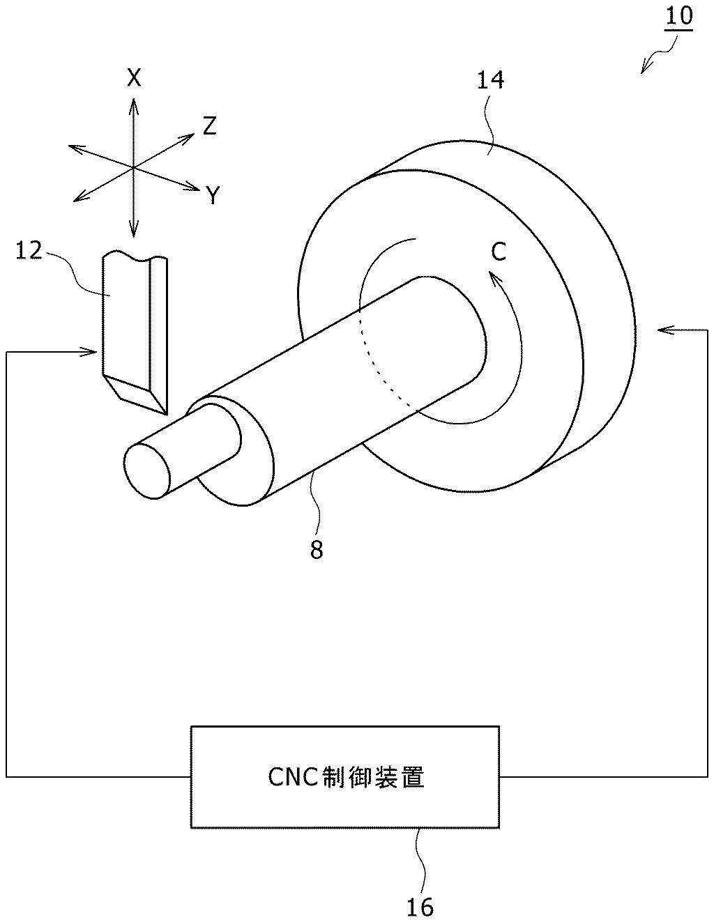
【解決手段】回転しながら切削加工される被工作物8に対し、回転により描かれる円の径方向に移動可能な切削工具12を用いて所定の半径rを有する2つの円柱を所定の中心点から夫々異なる位置に偏心させて形成する偏心体の製造方法であって、回転に同期させて切削工具12を径方向に移動させつつ、中心点からの距離がdとなる位置に偏心された第1の円柱20を形成する第1の工程と、回転に同期させて切削工具12を径方向に移動させつつ、第1の円柱20と対称となる位置であり中心点からの距離がdとなる位置に偏心された第2の円柱22を形成する第2の工程と、を備える。
【選択図】図1
Description
Claims (3)
- 回転しながら切削加工される被工作物に対し、前記回転により描かれる円の径方向に移動可能な切削工具を用いて所定の半径rを有する2つの円柱を所定の中心点から夫々異なる位置に偏心させて形成する偏心体の製造方法であって、
前記回転に同期させて前記切削工具を径方向に移動させつつ、前記中心点からの距離がdとなる位置に偏心された第1の円柱を形成する第1の工程と、
前記回転に同期させて前記切削工具を径方向に移動させつつ、前記第1の円柱と対称となる位置であり前記中心点からの距離がdとなる位置に偏心された第2の円柱を形成する第2の工程と、
を備えることを特徴とする偏心体の製造方法。 - 請求項1に記載の偏心体の製造方法において、
前記第1の工程は、前記被工作物の回転角をθとした場合に、−cosθ×d+rの計算式に基づいてX座標を算出し、sinθ×dの計算式に基づいてY座標を算出して求められたXY座標の位置に前記切削工具を移動させて切削して前記第1の円柱を形成し、
前記第2の工程は、cosθ×d+rの計算式に基づいてX座標を算出し、−sinθ×dの計算式に基づいてY座標を算出して求められたXY座標の位置に前記切削工具を移動させて切削して前記第2の円柱を形成することを特徴とする偏心体の製造方法。 - 請求項1に記載の偏心体の製造方法において、
前記第1の工程は、前記被工作物の回転角をθとした場合に、Y座標を0とし、数1に基づいてX座標を算出して求められたXY座標の位置に前記切削工具を移動させて切削して前記第1の円柱を形成し、
前記第2の工程は、Y座標を0とし、数2に基づいてX座標を算出して求められたXY座標の位置に前記切削工具を移動させて切削して前記第2の円柱を形成することを特徴とする偏心体の製造方法。
Applications Claiming Priority (2)
| Application Number | Priority Date | Filing Date | Title |
|---|---|---|---|
| JP2016099518 | 2016-05-18 | ||
| JP2016099518 | 2016-05-18 |
Publications (2)
| Publication Number | Publication Date |
|---|---|
| JP6139768B1 JP6139768B1 (ja) | 2017-05-31 |
| JP2017209779A true JP2017209779A (ja) | 2017-11-30 |
Family
ID=58794492
Family Applications (1)
| Application Number | Title | Priority Date | Filing Date |
|---|---|---|---|
| JP2016209327A Active JP6139768B1 (ja) | 2016-05-18 | 2016-10-26 | 偏心した2つの円柱が連なって形成された楕円状偏心体の製造方法 |
Country Status (1)
| Country | Link |
|---|---|
| JP (1) | JP6139768B1 (ja) |
Cited By (2)
| Publication number | Priority date | Publication date | Assignee | Title |
|---|---|---|---|---|
| CN109158616A (zh) * | 2018-08-20 | 2019-01-08 | 河南科技大学 | 一种等体积切除率中凸变椭圆活塞加工方法 |
| JP7309094B1 (ja) * | 2022-02-03 | 2023-07-14 | 三菱電機株式会社 | 制御装置、及びこれを備えた工作機械 |
Citations (3)
| Publication number | Priority date | Publication date | Assignee | Title |
|---|---|---|---|---|
| JPS5494185A (en) * | 1978-01-10 | 1979-07-25 | Ishikawajima Harima Heavy Ind Co Ltd | Universal machine tool |
| JPS62107901A (ja) * | 1985-11-01 | 1987-05-19 | Yaskawa Electric Mfg Co Ltd | 特殊断面形状切削機能付nc旋盤 |
| JP2003266202A (ja) * | 2002-03-20 | 2003-09-24 | Komatsu Machinery Corp | クランクシャフトの旋削加工装置及びその旋削加工方法 |
-
2016
- 2016-10-26 JP JP2016209327A patent/JP6139768B1/ja active Active
Patent Citations (3)
| Publication number | Priority date | Publication date | Assignee | Title |
|---|---|---|---|---|
| JPS5494185A (en) * | 1978-01-10 | 1979-07-25 | Ishikawajima Harima Heavy Ind Co Ltd | Universal machine tool |
| JPS62107901A (ja) * | 1985-11-01 | 1987-05-19 | Yaskawa Electric Mfg Co Ltd | 特殊断面形状切削機能付nc旋盤 |
| JP2003266202A (ja) * | 2002-03-20 | 2003-09-24 | Komatsu Machinery Corp | クランクシャフトの旋削加工装置及びその旋削加工方法 |
Cited By (6)
| Publication number | Priority date | Publication date | Assignee | Title |
|---|---|---|---|---|
| CN109158616A (zh) * | 2018-08-20 | 2019-01-08 | 河南科技大学 | 一种等体积切除率中凸变椭圆活塞加工方法 |
| CN109158616B (zh) * | 2018-08-20 | 2020-01-07 | 河南科技大学 | 一种等体积切除率中凸变椭圆活塞加工方法 |
| JP7309094B1 (ja) * | 2022-02-03 | 2023-07-14 | 三菱電機株式会社 | 制御装置、及びこれを備えた工作機械 |
| WO2023148870A1 (ja) * | 2022-02-03 | 2023-08-10 | 三菱電機株式会社 | 制御装置、及びこれを備えた工作機械 |
| DE112022005097T5 (de) | 2022-02-03 | 2024-08-29 | Dmg Mori Co., Ltd. | Steuerungsvorrichtung und Werkzeugmaschine die diese umfasst |
| DE112022005097B4 (de) * | 2022-02-03 | 2025-09-11 | Dmg Mori Co., Ltd. | Steuerungsvorrichtung und Werkzeugmaschine die diese umfasst |
Also Published As
| Publication number | Publication date |
|---|---|
| JP6139768B1 (ja) | 2017-05-31 |
Similar Documents
| Publication | Publication Date | Title |
|---|---|---|
| CA2537155C (en) | Grinding machine with concentricity correction | |
| US10569348B2 (en) | Groove-forming method, control device for machine tool and tool path generating device | |
| JP6128640B2 (ja) | 傘歯車の歯切り加工方法および装置 | |
| KR0167626B1 (ko) | 원통형상 가공장치 | |
| KR101903507B1 (ko) | 톱니형 소재의 미세 기계가공을 위한 방법 및 장치, 그리고 상기 장치를 제어하는 프로그램 | |
| JPS59124544A (ja) | 数値制御装置の加工方式 | |
| JP5957872B2 (ja) | 加工方法および加工装置 | |
| CN109434219A (zh) | 一种四轴侧刃铣齿方法 | |
| US11933638B2 (en) | Method for detecting phase on gear, method for producing gear, method for detecting position on edge of workpiece, and machine tool for detecting phase on gear | |
| US20220009016A1 (en) | Gear machining apparatus and machining condition determination device | |
| CN105268999A (zh) | 数控车床随动车削非圆异形截面的加工方法 | |
| EP2868411B1 (en) | Control device for machine tool and machine tool | |
| JP6139768B1 (ja) | 偏心した2つの円柱が連なって形成された楕円状偏心体の製造方法 | |
| JP6469209B2 (ja) | 工具経路生成方法及び工具経路生成装置 | |
| EP3231553B1 (en) | Cutting method for inner circumferential face or outer circumferential face of work | |
| CN102059418B (zh) | 一种圆柱齿轮全闭环数控加工系统及加工方法 | |
| KR101200171B1 (ko) | 5축 cνc 가공기계를 이용한 드럼 캠의 황삭가공을 위한 후처리방법 | |
| JP6871675B2 (ja) | 歯車加工装置及び歯車加工方法 | |
| Tan | Face gearing with a conical involute pinion: Part 2—The face gear: Meshing with the pinion, tooth geometry and generation | |
| JP2018130781A (ja) | Nc旋盤及びこれを用いた切削加工方法 | |
| CN105828990A (zh) | 多轴自动车床 | |
| JP2002137119A (ja) | マシニングセンタによる歯車の加工方法 | |
| Zhang et al. | A CNC program module based on polar coordinate system | |
| KR20240147538A (ko) | 기어 가공 장치 | |
| Fišer et al. | Radial Cam Grinder with a Camera Inspection |
Legal Events
| Date | Code | Title | Description |
|---|---|---|---|
| A521 | Request for written amendment filed |
Free format text: JAPANESE INTERMEDIATE CODE: A523 Effective date: 20170414 |
|
| TRDD | Decision of grant or rejection written | ||
| A01 | Written decision to grant a patent or to grant a registration (utility model) |
Free format text: JAPANESE INTERMEDIATE CODE: A01 Effective date: 20170425 |
|
| A61 | First payment of annual fees (during grant procedure) |
Free format text: JAPANESE INTERMEDIATE CODE: A61 Effective date: 20170427 |
|
| R150 | Certificate of patent or registration of utility model |
Ref document number: 6139768 Country of ref document: JP Free format text: JAPANESE INTERMEDIATE CODE: R150 |
|
| R250 | Receipt of annual fees |
Free format text: JAPANESE INTERMEDIATE CODE: R250 |
|
| R250 | Receipt of annual fees |
Free format text: JAPANESE INTERMEDIATE CODE: R250 |
|
| R250 | Receipt of annual fees |
Free format text: JAPANESE INTERMEDIATE CODE: R250 |