JP2017209902A - Filament winding device - Google Patents
Filament winding device Download PDFInfo
- Publication number
- JP2017209902A JP2017209902A JP2016105533A JP2016105533A JP2017209902A JP 2017209902 A JP2017209902 A JP 2017209902A JP 2016105533 A JP2016105533 A JP 2016105533A JP 2016105533 A JP2016105533 A JP 2016105533A JP 2017209902 A JP2017209902 A JP 2017209902A
- Authority
- JP
- Japan
- Prior art keywords
- fiber bundle
- liner
- fiber
- width
- pins
- Prior art date
- Legal status (The legal status is an assumption and is not a legal conclusion. Google has not performed a legal analysis and makes no representation as to the accuracy of the status listed.)
- Pending
Links
Images


Landscapes
- Guides For Winding Or Rewinding, Or Guides For Filamentary Materials (AREA)
- Pressure Vessels And Lids Thereof (AREA)
- Moulding By Coating Moulds (AREA)
Abstract
【課題】繊維束の幅を調整することができるフィラメントワインディング装置を提供する。
【解決手段】本発明に係るフィラメントワインディング装置1は、繊維束Wをライナー2へ巻回するガイド部を備え、ガイド部は、ガイド部の出口から見て繊維束Wの搬送方向の上流における繊維束Wの幅方向端部に設けられ且つ該幅方向に移動可能な複数のピン20を有し、複数のピン20は、繊維束Wの幅方向に移動することによりピン20同士の間隔を調整する。
【選択図】図2A filament winding apparatus capable of adjusting the width of a fiber bundle is provided.
A filament winding apparatus 1 according to the present invention includes a guide portion for winding a fiber bundle W around a liner 2, and the guide portion is a fiber upstream in the conveying direction of the fiber bundle W as viewed from the outlet of the guide portion. It has a plurality of pins 20 provided at the end in the width direction of the bundle W and movable in the width direction, and the plurality of pins 20 adjusts the distance between the pins 20 by moving in the width direction of the fiber bundle W. To do.
[Selection] Figure 2
Description
本発明は、フィラメントワインディング装置に関する。 The present invention relates to a filament winding apparatus.
従来、ライナーの外周面に補強用繊維を巻き付けていくフィラメントワインディング装置が知られている。このようなフィラメントワインディング装置は、ボビンから補強用繊維を引出しつつ該補強用繊維をライナーの外周面に巻き付ける。なお、ボビンから引出された補強用繊維は、複数個のガイド部を介してライナーへ案内される。なお、ライナーは、略円筒状の胴体部と、該胴体部の両端部を閉鎖する略半球状のドーム部とを有する密閉円筒状の容器である。 2. Description of the Related Art Conventionally, a filament winding apparatus that winds reinforcing fibers around an outer peripheral surface of a liner is known. Such a filament winding apparatus winds the reinforcing fiber around the outer peripheral surface of the liner while drawing the reinforcing fiber from the bobbin. The reinforcing fiber drawn out from the bobbin is guided to the liner through a plurality of guide portions. The liner is a sealed cylindrical container having a substantially cylindrical body portion and a substantially hemispherical dome portion that closes both ends of the body portion.
上記フィラメントワインディング装置において、補強用繊維の束(以下、繊維束とも称する)をライナーに巻回したときに、繊維束の幅方向の不均一な厚みによる段差でボイドが発生するという課題がある。この課題を解決することを意図して、例えば下記特許文献1では、ガイド部の下流において、繊維の幅を規制する櫛部材を設けている。この櫛部材を設けることによって、ガイド部を介して供給される複数の繊維束のそれぞれは、櫛部材を通り、その間隔が一定にされた後、ライナーへ案内される。下記特許文献1によれば、繊維束の間の隙間や重なりが発生するのを防止して、製品の品質を安定させることができる、とされている。
In the filament winding apparatus, when a bundle of reinforcing fibers (hereinafter also referred to as a fiber bundle) is wound around a liner, there is a problem that a void is generated at a step due to an uneven thickness in the width direction of the fiber bundle. In order to solve this problem, for example, in
上記櫛部材では、繊維束間の間隔を一定にすることは可能であるものの、繊維同士の位置を任意に決めることができないため、繊維束の幅を制御することができなかった。 In the above comb member, although the interval between the fiber bundles can be made constant, the position of the fibers cannot be arbitrarily determined, and thus the width of the fiber bundle cannot be controlled.
本発明はこのような課題に鑑みてなされたものであり、その目的は、繊維束の幅を調整することができるフィラメントワインディング装置を提供することにある。 This invention is made | formed in view of such a subject, The objective is to provide the filament winding apparatus which can adjust the width | variety of a fiber bundle.
上記課題を解決するために本発明に係るフィラメントワインディング装置は、ライナーの外周に繊維束を巻回して高圧タンクを製造するフィラメントワインディング装置において、前記繊維束を前記ライナーへ巻回するガイド部を備え、前記ガイド部は、前記ガイド部の出口から見て前記繊維束の搬送方向の上流における前記繊維束の幅方向端部に設けられ且つ該幅方向に移動可能な複数のピンを有し、前記複数のピンは、前記繊維束の幅方向に移動することにより前記ピン同士の間隔を調整する。 In order to solve the above problems, a filament winding apparatus according to the present invention is a filament winding apparatus that manufactures a high-pressure tank by winding a fiber bundle around an outer periphery of a liner, and includes a guide unit that winds the fiber bundle around the liner. The guide portion has a plurality of pins that are provided at an end portion in the width direction of the fiber bundle upstream of the conveyance direction of the fiber bundle as viewed from the exit of the guide portion and are movable in the width direction, The plurality of pins adjusts the interval between the pins by moving in the width direction of the fiber bundle.
本発明では、ライナーへ繊維束を案内するガイド部に、繊維束の幅方向端部に配置されて該幅方向に移動可能な複数のピンを設け、当該ピン同士の間隔を調整する。このような構成を備えることによって、繊維同士の位置を定めることができるようになり、繊維束の幅を調整することができる。 In this invention, the guide part which guides a fiber bundle to a liner is provided with a plurality of pins arranged at the end in the width direction of the fiber bundle and movable in the width direction, and the interval between the pins is adjusted. By providing such a configuration, the positions of the fibers can be determined, and the width of the fiber bundle can be adjusted.
本発明によれば、繊維束の幅を調整することができるフィラメントワインディング装置を提供することができる。 ADVANTAGE OF THE INVENTION According to this invention, the filament winding apparatus which can adjust the width | variety of a fiber bundle can be provided.
以下添付図面を参照しながら本発明の実施形態について説明する。尚、以下の好ましい実施形態の説明は、例示に過ぎず、本発明、その適用物或いはその用途を制限することを意図するものではない。 Embodiments of the present invention will be described below with reference to the accompanying drawings. It should be noted that the following description of the preferred embodiment is merely an example, and is not intended to limit the present invention, its application, or its use.
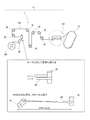
図1は、本発明の実施形態におけるフィラメントワインディング装置1(以下、「FW装置1」という)の構成図である。なお、図1には、FW装置1の構成要素ではないが、成形製品の形状を形作るライナー2も図示されている。
FIG. 1 is a configuration diagram of a filament winding apparatus 1 (hereinafter referred to as “
FW装置1は、繊維束W(例えば予め樹脂が含浸されたカーボン繊維等)を搬送するための繊維搬送経路部11を備え、繊維搬送経路部11は、繊維束Wをセットし巻出しを行う巻出部90と、繊維束Wを上流(巻出部90側)から下流側(ライナー2側)に搬送するための複数のローラRと、巻き出された繊維束Wを揃えてライナー2に案内するアイクチ案内部10とを備える。
The
巻出部90から巻き出された繊維束Wは、いくつものローラR等を経由し、アイクチ案内部10を通り、ライナー2に巻き付けられる。ライナー2は、その長手軸周りに回転駆動され、このライナー2の回転駆動によって繊維束Wに張力が与えられ、その張力の下で、繊維束Wがライナー2に緊密に巻きつけられることになる。
The fiber bundle W unwound from the
繊維束Wが搬送される繊維搬送経路部11は、以下の構成を備える。具体的には、図1に示すように、ローラRに対して繊維束Wが直角に掛かるようにローラRが配置されている。
The fiber conveyance path |
また、ローラRの角度を90°回転させる際は、ローラR間の距離が250mm以上となるように、ローラRが配置されている。 Further, when the angle of the roller R is rotated by 90 °, the roller R is arranged so that the distance between the rollers R is 250 mm or more.
上記のように配置されたローラRにより繊維束Wが下流側に搬送されることで、繊維束Wの幅が太い状態(繊維束Wの幅を維持した状態)でアイクチ案内部10に繊維束Wが案内される(図2の符号Bエリア参照)。アイクチ案内部10は、複数の繊維束Wを幅方向に揃えてライナー2に案内する機能を有し、ライナー2の外形に沿って移動する移動機構等を有する。アイクチ案内部10の構成については、図2を参照しながら後述する。
The fiber bundle W is conveyed to the downstream side by the roller R arranged as described above, so that the fiber bundle W is fed to the
なお、ライナー2は、成形製品の形状を形作る芯材となるもので、例えば高圧タンクを成形する場合は、タンクの内径に対応する筒である。ライナー2は、長手軸が回転可能に支持され、回転駆動機構によって長手軸周りに回転される。アイクチ案内部10によって幅方向に並べて揃えられた複数の繊維束Wは、その端部がライナー2に固定され、そのライナー2が回転駆動されることで、繊維束Wがライナー2の長手軸方向に並んでその外周に巻き取られる。所定の巻き数で繊維束Wがライナー2に巻き付けられ、製品の形状が作られると、その後硬化処理が行われ、エポキシ樹脂が硬化して、繊維強化樹脂複合製品が成形される。
The
続いて、図1に示した複数のローラRを経由して搬送される繊維束Wを揃えてライナー2に巻き付けるアイクチ案内部10の構成について説明する。図2は、アイクチ案内部10の構成を示す概略斜視図である。なお、ローラRやピン20等の駆動は、図示しない制御部により制御される。
Next, the configuration of the
アイクチ案内部10は、アイクチ案内部10の出口からみて繊維束Wの搬送方向の上流において、繊維束Wの幅方向(繊維束Wの搬送方向に垂直な方向)端部に移動可能に配置される複数のピン20を備える(図2の符号Cエリア参照)。ピン20同士の間隔を調整することにより、繊維同士の位置を定めることができ、繊維束Wの幅(繊維間ピッチ)を調整することができる。本実施形態では、4本のピン20が繊維束Wの幅方向両側に配置されるが、この例に限定されず、繊維間ピッチを調整可能であれば、適宜その本数を変更することができる。
The
またアイクチ案内部10は、繊維束WをS字に掛け摩擦により繊維間ピッチを保持するためのローラRを複数備える(図2の符号Dエリア参照)。図2の符号Dエリア近傍に配置される2本のローラRのうち、上流側(図2では左側)のローラを前ローラRd1、下流側のローラを後ローラRd2と呼ぶことにすると、繊維束Wは、前ローラRd1の下側外周、後ローラRd2の上側外周にそれぞれ接触し(すなわちS字に掛けられて)、下流側に搬送される。
The
またアイクチ案内部10は、繊維の位置を保持するため、ローラRを回転させて繊維束WをS字に掛けるローラRを複数備える(図2の符号Eエリア参照)。図2の符号Eエリア近傍に配置される3本のローラRのうち、上流側のローラを前ローラRe1、中央側のローラを中央ローラRe2、下流側のローラを後ローラRe3と呼ぶことにすると、繊維束Wは、前ローラRe1の下側外周、中央ローラRe2の上側外周、後ローラRe3の下側外周にそれぞれ接触し(すなわち、S字に掛けられて)、下流側のライナー2(図1参照)に案内される。
Further, the
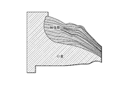
ところで、繊維束Wが、ライナーの端部に設けられた口金の周辺に巻回される場合において、下地となるヘリカル層よりも中心軸側に近い位置へと繊維束が積層される場合、補強層の一部はその厚み方向に蛇行する(図3参照)。これは下地となるヘリカル層の厚みの不均一性が転写されるためであり、蛇行した層は十分な強度を発揮することができない。その結果、タンク容器のドーム部において設計上の強度とならないおそれがある。 By the way, when the fiber bundle W is wound around the base provided at the end portion of the liner, the fiber bundle is laminated to a position closer to the central axis side than the helical layer serving as a base. A part of the layer meanders in the thickness direction (see FIG. 3). This is because nonuniformity of the thickness of the underlying helical layer is transferred, and the meandering layer cannot exhibit sufficient strength. As a result, the design strength may not be achieved in the dome portion of the tank container.
そこで、本発明者らは、上記のような層の蛇行を抑制して強度を向上させるための研究を行った。具体的には、本発明者らは、図4に示すように、巻位置、繊維束、角度をそれぞれノミナル値から公差最大と公差最小の3条件に変化させて、繊維歪の発生量について検証した。 Therefore, the present inventors conducted research for improving the strength by suppressing the meandering of the layer as described above. Specifically, as shown in FIG. 4, the inventors changed the winding position, fiber bundle, and angle from the nominal value to three conditions of maximum tolerance and minimum tolerance, respectively, and verified the amount of fiber strain generated. did.
図4(A)は、1層目における、巻位置、繊維束、角度をそれぞれノミナル値から公差最大と公差最小の3条件に変化させたときの繊維歪を示すグラフである。図4(B)は、2層目における、位置、繊維束、角度をそれぞれノミナル値から公差最大と公差最小の3条件に変化させたときの繊維歪を示すグラフである。 FIG. 4A is a graph showing fiber strain when the winding position, fiber bundle, and angle in the first layer are each changed from the nominal value to three conditions of maximum tolerance and minimum tolerance. FIG. 4B is a graph showing the fiber strain when the position, fiber bundle, and angle in the second layer are changed from the nominal value to the three conditions of maximum tolerance and minimum tolerance.
図4(A)に示すように、1層目における繊維束の太さ(幅)が強度に大きく寄与すること、すなわち、繊維束の幅を広くすると繊維歪を低減できるという知見を本発明者らは見出した。言い換えれば、繊維束の幅を調整できれば、図3を参照して説明したようなドーム部(口金周辺等)に積層される繊維束の厚みの不均一性が解消され、強度を向上できるという知見を本発明者らは見出した。 As shown in FIG. 4A, the present inventors have found that the thickness (width) of the fiber bundle in the first layer greatly contributes to strength, that is, the fiber strain can be reduced by increasing the width of the fiber bundle. Found. In other words, if the width of the fiber bundle can be adjusted, the knowledge that the unevenness of the thickness of the fiber bundle laminated on the dome (such as the periphery of the base) as described with reference to FIG. The present inventors have found out.
上記本発明者らが見出した知見に基づき、本実施形態では以下のように繊維束Wを案内する。すなわち、本実施形態のFW装置1では、繊維束Wの幅を維持した状態でアイクチ案内部10に繊維束Wが案内され、またアイクチ案内部10からライナー2に向けて、繊維束Wの太さを維持した状態で繊維束Wがライナー2に案内される。これにより、FW装置1から供給される繊維束Wは、その幅が維持された状態でライナー2の外周に積層されるので、繊維束の太さに起因して発生する繊維歪を低減することができる。つまり、従来において問題となっていた、ドーム部(口金周辺)に積層される繊維束の厚みの不均一性により、補強層の一部に蛇行(図3参照)が生じることが抑制される。その結果、例えばドーム部において設計通りの強度を確保するために設計上の数値以上に繊維を積層することがなくなるため、繊維層の厚みが軽減される。これにより、FW装置1を用いて作製される高圧タンクの軽量化を図りつつ、強度を向上させることができる。
Based on the knowledge found by the inventors, the present embodiment guides the fiber bundle W as follows. That is, in the
アイクチ案内部10による繊維束Wの幅(繊維間ピッチ)を調整した結果、ライナー2のドーム部2bには、以下のように繊維が巻回されることが好ましい。この詳細について図5を参照しながら説明する。
As a result of adjusting the width (interfiber pitch) of the fiber bundle W by the ikuchi guide
ライナー2は、図5に示すように、略円筒状の胴体部2aと、当該胴体部2aの両端に設けられるドーム部2bとを有し、ドーム部2bの頂上には口金3が設けられる。
As shown in FIG. 5, the
ライナー2の外周には次のように繊維束が巻回される。具体的には、口金3の最も細くなる部位(図5に示す首部)から、巻付け位置が首部より繊維束幅以上に離れた層(以下、「首部離間層」と称する)であり、且つ次に巻きつけられる層が、首部離間層より首部に近い位置に巻かれる場合、首部離間層の繊維束の幅が胴体部2aの1/2倍以上の太さを保持している。これにより、首部離間層の次に巻かれる層の厚み方向(図3における上下方向)の蛇行を低減することができる。このため、CFRP層の強度を向上させ、余剰な繊維を巻付ける必要がなくなる結果、高圧タンクの軽量化を実現することができる。
A fiber bundle is wound around the outer periphery of the
以上、具体例を参照しつつ本発明の実施形態について説明した。しかし、本発明はこれらの具体例に限定されるものではない。すなわち、これら具体例に、当業者が適宜設計変更を加えたものも、本発明の特徴を備えている限り、本発明の範囲に包含される。前述した各具体例が備える各要素およびその配置、材料、条件、形状、サイズなどは、例示したものに限定されるわけではなく適宜変更することができる。 The embodiments of the present invention have been described above with reference to specific examples. However, the present invention is not limited to these specific examples. In other words, those specific examples that have been appropriately modified by those skilled in the art are also included in the scope of the present invention as long as they have the characteristics of the present invention. Each element included in each of the specific examples described above and their arrangement, material, condition, shape, size, and the like are not limited to those illustrated, and can be appropriately changed.
1:フィラメントワインディング装置
2:ライナー
2a:胴体部
2b:ドーム部
3:口金
10:アイクチ案内部(ガイド部)
11:繊維搬送経路部
20:ピン
90:巻出部
R:ローラ
W:繊維束
1: Filament winding device 2:
11: Fiber conveyance path part 20: Pin 90: Unwinding part R: Roller W: Fiber bundle
Claims (1)
前記繊維束を前記ライナーへ巻回するガイド部を備え、
前記ガイド部は、前記ガイド部の出口から見て前記繊維束の搬送方向の上流における前記繊維束の幅方向端部に設けられ且つ該幅方向に移動可能な複数のピンを有し、
前記複数のピンは、前記繊維束の幅方向に移動することにより前記ピン同士の間隔を調整することを特徴とするフィラメントワインディング装置。 In a filament winding apparatus for manufacturing a high-pressure tank by winding a fiber bundle around the outer periphery of a liner,
A guide portion for winding the fiber bundle around the liner;
The guide portion has a plurality of pins provided at an end in the width direction of the fiber bundle upstream of the fiber bundle in the conveyance direction when viewed from the outlet of the guide portion and movable in the width direction;
The filament winding apparatus according to claim 1, wherein the plurality of pins are moved in the width direction of the fiber bundle to adjust intervals between the pins.
Priority Applications (1)
| Application Number | Priority Date | Filing Date | Title |
|---|---|---|---|
| JP2016105533A JP2017209902A (en) | 2016-05-26 | 2016-05-26 | Filament winding device |
Applications Claiming Priority (1)
| Application Number | Priority Date | Filing Date | Title |
|---|---|---|---|
| JP2016105533A JP2017209902A (en) | 2016-05-26 | 2016-05-26 | Filament winding device |
Publications (1)
| Publication Number | Publication Date |
|---|---|
| JP2017209902A true JP2017209902A (en) | 2017-11-30 |
Family
ID=60474721
Family Applications (1)
| Application Number | Title | Priority Date | Filing Date |
|---|---|---|---|
| JP2016105533A Pending JP2017209902A (en) | 2016-05-26 | 2016-05-26 | Filament winding device |
Country Status (1)
| Country | Link |
|---|---|
| JP (1) | JP2017209902A (en) |
Cited By (2)
| Publication number | Priority date | Publication date | Assignee | Title |
|---|---|---|---|---|
| JP2022130133A (en) * | 2021-02-25 | 2022-09-06 | 株式会社Subaru | Tape arrangement mechanism |
| JP2024093044A (en) * | 2022-12-27 | 2024-07-09 | 本田技研工業株式会社 | Filament winding device and filament winding method |
Citations (3)
| Publication number | Priority date | Publication date | Assignee | Title |
|---|---|---|---|---|
| JPH04312837A (en) * | 1991-04-12 | 1992-11-04 | Fuji Heavy Ind Ltd | Head for filament winding molding equipment |
| JPH0977370A (en) * | 1995-09-07 | 1997-03-25 | Hitachi Chem Co Ltd | Width adjusting device for fibers pulled and arranged in one direction |
| JP2011093276A (en) * | 2009-11-02 | 2011-05-12 | Toyota Motor Corp | Filament winding system, system of manufacturing pressure vessel, and method of manufacturing pressure vessel |
-
2016
- 2016-05-26 JP JP2016105533A patent/JP2017209902A/en active Pending
Patent Citations (3)
| Publication number | Priority date | Publication date | Assignee | Title |
|---|---|---|---|---|
| JPH04312837A (en) * | 1991-04-12 | 1992-11-04 | Fuji Heavy Ind Ltd | Head for filament winding molding equipment |
| JPH0977370A (en) * | 1995-09-07 | 1997-03-25 | Hitachi Chem Co Ltd | Width adjusting device for fibers pulled and arranged in one direction |
| JP2011093276A (en) * | 2009-11-02 | 2011-05-12 | Toyota Motor Corp | Filament winding system, system of manufacturing pressure vessel, and method of manufacturing pressure vessel |
Cited By (5)
| Publication number | Priority date | Publication date | Assignee | Title |
|---|---|---|---|---|
| JP2022130133A (en) * | 2021-02-25 | 2022-09-06 | 株式会社Subaru | Tape arrangement mechanism |
| JP7595484B2 (en) | 2021-02-25 | 2024-12-06 | 株式会社Subaru | Tape arrangement mechanism |
| JP2024093044A (en) * | 2022-12-27 | 2024-07-09 | 本田技研工業株式会社 | Filament winding device and filament winding method |
| JP7788370B2 (en) | 2022-12-27 | 2025-12-18 | 本田技研工業株式会社 | Filament winding device and filament winding method |
| US12605907B2 (en) | 2022-12-27 | 2026-04-21 | Honda Motor Co., Ltd. | Filament winding device and filament winding method |
Similar Documents
| Publication | Publication Date | Title |
|---|---|---|
| US10232548B2 (en) | Manufacturing method of tank | |
| US7905442B2 (en) | Filament winding apparatus | |
| US7942359B2 (en) | Carbon fiber package and process for producing the same | |
| JP4983950B2 (en) | Fiber bundle traversing device, fiber bundle package manufacturing apparatus and manufacturing method | |
| JP6423303B2 (en) | Manufacturing apparatus and manufacturing method for fiber reinforced thermoplastic resin tape | |
| CN104736325A (en) | Hoop winding device, wire winding device and manufacturing method of tank | |
| JP2016010904A (en) | Fiber structure molding equipment | |
| JP6801620B2 (en) | How to manufacture high pressure tank | |
| JP2016166617A (en) | High-pressure tank and manufacturing method of high-pressure tank | |
| JP2017209902A (en) | Filament winding device | |
| KR102713686B1 (en) | Apparatus of manufacturing continuous fiber reinforced thermoplastic composite | |
| JP2019072895A (en) | Filament winding device | |
| WO2016009735A1 (en) | Manufacturing device and manufacturing method for fiber-reinforced thermoplastic resin tape | |
| JP4449673B2 (en) | Fiber bundle winding device, fiber bundle package manufacturing apparatus, and fiber bundle package manufacturing method | |
| JP2017177660A (en) | Cylindrical manufacturing apparatus and manufacturing method thereof | |
| JP2010089954A (en) | Thread passage guide device | |
| KR20210144127A (en) | Creel device for unwinding | |
| KR102394598B1 (en) | Fiber winding apparatus | |
| JP2005225644A (en) | Traverse guide device for winder and method for manufacturing winder and carbon fiber bundle package | |
| JP7355768B2 (en) | filament winding device | |
| JP2005088536A (en) | Fiber reinforced composite material manufacturing apparatus, manufacturing method and pressure vessel | |
| JP6702223B2 (en) | Filament winding equipment | |
| JP6519454B2 (en) | Filament winding device | |
| JP6662314B2 (en) | Fiber feeder | |
| KR102699753B1 (en) | Unwinding creel device |
Legal Events
| Date | Code | Title | Description |
|---|---|---|---|
| A621 | Written request for application examination |
Free format text: JAPANESE INTERMEDIATE CODE: A621 Effective date: 20190122 |
|
| A977 | Report on retrieval |
Free format text: JAPANESE INTERMEDIATE CODE: A971007 Effective date: 20191226 |
|
| A131 | Notification of reasons for refusal |
Free format text: JAPANESE INTERMEDIATE CODE: A131 Effective date: 20200131 |
|
| A02 | Decision of refusal |
Free format text: JAPANESE INTERMEDIATE CODE: A02 Effective date: 20200803 |