「第1実施形態」
本発明に係る第1実施形態を図1〜図5に基づいて説明する。なお、以下においては、説明の便宜上、図面における上側を「上」とし、図面における下側を「下」として説明する。
“First Embodiment”
1st Embodiment which concerns on this invention is described based on FIGS. In the following, for convenience of explanation, the upper side in the drawing is referred to as “upper” and the lower side in the drawing is referred to as “lower”.
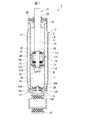
第1実施形態の緩衝器1は、図1に示すように、いわゆる複筒型の油圧緩衝器であり、作動液体としての油液(図示略)が封入されたシリンダ2を有している。シリンダ2は、円筒状の金属製の内筒3と、この内筒3よりも大径で内筒3を覆うように同心状に設けられた有底円筒状の外筒4とを有しており、内筒3と外筒4との間にリザーバ室6が形成されている。
As shown in FIG. 1, the shock absorber 1 of the first embodiment is a so-called double cylinder type hydraulic shock absorber, and includes a cylinder 2 in which an oil liquid (not shown) as a working liquid is enclosed. The cylinder 2 has a cylindrical metal inner cylinder 3 and a bottomed cylindrical outer cylinder 4 that is concentrically provided so as to cover the inner cylinder 3 with a larger diameter than the inner cylinder 3. A reservoir chamber 6 is formed between the inner cylinder 3 and the outer cylinder 4.
外筒4は、円筒状の金属製の胴部材11と、胴部材11の下部を閉塞する金属製の底部材12とからなっている。底部材12には、胴部材11とは反対側となる外側に取付アイ13が固定されている。
The outer cylinder 4 includes a cylindrical metal body member 11 and a metal bottom member 12 that closes a lower portion of the body member 11. A mounting eye 13 is fixed to the bottom member 12 on the outer side opposite to the body member 11.
緩衝器1は、シリンダ2の内筒3内に摺動可能に嵌装されたピストン16を備えている。内筒3内に設けられたこのピストン16は、内筒3内をピストン16の軸方向の一側にある上室17と、ピストン16の軸方向の他側にある下室18とに区画している。内筒3内の上室17および下室18内には作動流体としての油液が封入され、内筒3と外筒4との間のリザーバ室6内には作動流体としての油液とガスとが封入されている。
The shock absorber 1 includes a piston 16 slidably fitted in the inner cylinder 3 of the cylinder 2. The piston 16 provided in the inner cylinder 3 divides the inside of the inner cylinder 3 into an upper chamber 17 on one side in the axial direction of the piston 16 and a lower chamber 18 on the other side in the axial direction of the piston 16. ing. Oil liquid as working fluid is sealed in the upper chamber 17 and the lower chamber 18 in the inner cylinder 3, and oil liquid and gas as working fluid are placed in the reservoir chamber 6 between the inner cylinder 3 and the outer cylinder 4. And are enclosed.
緩衝器1は、一端側がシリンダ2の内筒3内に配置されてピストン16に接続されると共に他端側がシリンダ2の外部に延出される金属製のピストンロッド21を備えている。ピストン16およびピストンロッド21は一体に移動する。ピストンロッド21がシリンダ2からの突出量を増やす伸び行程において、ピストン16は上室17側へ移動することになり、ピストンロッド21がシリンダ2からの突出量を減らす縮み行程において、ピストン16は下室18側へ移動することになる。
The shock absorber 1 includes a metal piston rod 21 having one end side disposed in the inner cylinder 3 of the cylinder 2 and connected to the piston 16, and the other end side extending to the outside of the cylinder 2. The piston 16 and the piston rod 21 move together. In the expansion stroke in which the piston rod 21 increases the amount of protrusion from the cylinder 2, the piston 16 moves to the upper chamber 17 side. In the contraction stroke in which the piston rod 21 decreases the amount of protrusion from the cylinder 2, the piston 16 moves downward. It moves to the chamber 18 side.
内筒3および外筒4の上端開口側には、ロッドガイド22が嵌合されており、外筒4にはロッドガイド22よりもシリンダ2の外部側である上側にシール部材23が装着されている。ロッドガイド22およびシール部材23は、いずれも環状をなしている。ピストンロッド21は、これらロッドガイド22およびシール部材23のそれぞれの内側に摺動可能に挿通されており、これらロッドガイド22およびシール部材23を介してシリンダ2の外部に延出されている。上室17は、内筒3内のピストン16とロッドガイド22との間に形成されている。
A rod guide 22 is fitted to the upper end opening side of the inner cylinder 3 and the outer cylinder 4, and a seal member 23 is attached to the outer cylinder 4 on the upper side, which is the outer side of the cylinder 2, relative to the rod guide 22. Yes. Both the rod guide 22 and the seal member 23 are annular. The piston rod 21 is slidably inserted inside the rod guide 22 and the seal member 23, and extends outside the cylinder 2 via the rod guide 22 and the seal member 23. The upper chamber 17 is formed between the piston 16 in the inner cylinder 3 and the rod guide 22.
ここで、ロッドガイド22は、ピストンロッド21を、その径方向移動を規制しつつ軸方向移動可能に支持して、このピストンロッド21の移動を案内する。シール部材23は、その外周部で外筒4に密着し、その内周部で、軸方向に移動するピストンロッド21の外周部に摺接して、内筒3内の油液と、外筒4内のリザーバ室6の高圧ガスおよび油液とが外部に漏洩するのを防止する。
Here, the rod guide 22 supports the piston rod 21 so as to be movable in the axial direction while restricting its radial movement, and guides the movement of the piston rod 21. The seal member 23 is in close contact with the outer cylinder 4 at the outer peripheral portion thereof, and is in sliding contact with the outer peripheral portion of the piston rod 21 that moves in the axial direction at the inner peripheral portion thereof. This prevents the high-pressure gas and oil liquid in the inner reservoir chamber 6 from leaking to the outside.
ロッドガイド22は、その外周部が、下部よりも上部が大径となる段差状をなしており、小径の下部において内筒3の上端の内周部に嵌合し大径の上部において外筒4の上部の内周部に嵌合する。外筒4の底部材12上には、下室18とリザーバ室6とを画成するベースバルブ25が設置されており、このベースバルブ25に内筒3の下端の内周部が嵌合されている。外筒4の上端部は、径方向内方に加締められて加締部26とされ、この加締部26とロッドガイド22とがシール部材23を挟持している。下室18は、内筒3内のピストン16とベースバルブ25との間に形成されている。
The rod guide 22 has a step shape in which the outer peripheral portion has a larger diameter at the upper portion than the lower portion. The rod guide 22 is fitted to the inner peripheral portion at the upper end of the inner tube 3 at the lower portion of the small diameter, and the outer tube at the upper portion of the large diameter. 4 is fitted to the inner periphery of the upper part. A base valve 25 that defines a lower chamber 18 and a reservoir chamber 6 is installed on the bottom member 12 of the outer cylinder 4, and the inner peripheral portion of the lower end of the inner cylinder 3 is fitted to the base valve 25. ing. The upper end portion of the outer cylinder 4 is caulked inward in the radial direction to form a caulking portion 26, and the caulking portion 26 and the rod guide 22 sandwich the seal member 23. The lower chamber 18 is formed between the piston 16 in the inner cylinder 3 and the base valve 25.
ピストンロッド21は、主軸部31と、これより小径の取付軸部32とを有しており、主軸部31の取付軸部32側の端部は、軸直交方向に広がる軸段部33となっている。取付軸部32は、シリンダ2内に配置されており、その主軸部31とは反対側の端部にオネジ34が形成されている。取付軸部32には、ピストン16が、オネジ34に螺合された金属製のナット35により締結されている。言い換えれば、ピストンロッド21がピストン16にナット35により締結されている。
The piston rod 21 has a main shaft portion 31 and a mounting shaft portion 32 having a smaller diameter than the main shaft portion 31, and an end portion of the main shaft portion 31 on the mounting shaft portion 32 side is a shaft step portion 33 that extends in the direction perpendicular to the axis. ing. The attachment shaft portion 32 is disposed in the cylinder 2, and a male screw 34 is formed at the end opposite to the main shaft portion 31. The piston 16 is fastened to the mounting shaft portion 32 by a metal nut 35 screwed into the male screw 34. In other words, the piston rod 21 is fastened to the piston 16 by the nut 35.
緩衝器1は、例えばピストンロッド21のシリンダ2からの突出部分が上部に配置されて車体により支持され、シリンダ2側の取付アイ13が下部に配置されて車輪側に連結される。これとは逆に、シリンダ2側が車体により支持され、ピストンロッド21が車輪側に連結されるようにしても良い。車輪が走行に伴って振動すると該振動に伴ってシリンダ2とピストンロッド21との位置が相対的に変化するが、上記変化はピストン16に形成された流路の流体抵抗により抑制される。
In the shock absorber 1, for example, a protruding portion of the piston rod 21 from the cylinder 2 is arranged at the upper part and supported by the vehicle body, and the mounting eye 13 on the cylinder 2 side is arranged at the lower part and connected to the wheel side. On the contrary, the cylinder 2 side may be supported by the vehicle body, and the piston rod 21 may be connected to the wheel side. When the wheels vibrate as the vehicle travels, the positions of the cylinder 2 and the piston rod 21 change relatively with the vibrations, but the change is suppressed by the fluid resistance of the flow path formed in the piston 16.
図2に示すように、ピストン16は、軸方向の軸段部33側から順に、規制部材37と、当接ディスク38と、小径ディスク39と、複数枚の単体ディスクが積層されて構成されるディスクバルブ40と、ピストン本体41と、複数枚の単体ディスクが積層されて構成されるディスクバルブ42と、複数枚の単体ディスクが積層されて構成される小径ディスク43と、を有している。これら規制部材37、当接ディスク38、小径ディスク39、ディスクバルブ40、ピストン本体41、ディスクバルブ42および小径ディスク43は、いずれも金属製である。また、ピストン16は、ピストン本体41の外周面に装着されて、内筒3の内周面に摺接する円環帯状の合成樹脂製の摺接部材44を有している。
As shown in FIG. 2, the piston 16 is configured by stacking a regulating member 37, a contact disk 38, a small-diameter disk 39, and a plurality of single disks in order from the axial step 33 side in the axial direction. It has a disk valve 40, a piston body 41, a disk valve 42 formed by stacking a plurality of single disks, and a small diameter disk 43 formed by stacking a plurality of single disks. The restriction member 37, the contact disk 38, the small diameter disk 39, the disk valve 40, the piston body 41, the disk valve 42, and the small diameter disk 43 are all made of metal. The piston 16 has an annular belt-shaped synthetic resin sliding contact member 44 attached to the outer peripheral surface of the piston main body 41 and in sliding contact with the inner peripheral surface of the inner cylinder 3.
規制部材37は、円環状をなしており、取付軸部32が内周側に嵌合される。規制部材37は、外径が軸段部33の外径よりも大径となっている。規制部材37は、いずれも薄板からなる当接ディスク38、小径ディスク39、ディスクバルブ40を構成する単体ディスク、ディスクバルブ42を構成する単体ディスクおよび小径ディスク43を構成する単体ディスクよりも厚さが厚く高剛性となっている。
The restricting member 37 has an annular shape, and the attachment shaft portion 32 is fitted on the inner peripheral side. The regulating member 37 has an outer diameter larger than the outer diameter of the shaft step portion 33. The restricting member 37 is thinner than the contact disk 38, the small diameter disk 39, the single disk constituting the disk valve 40, the single disk constituting the disk valve 42, and the single disk constituting the small diameter disk 43. It is thick and highly rigid.
当接ディスク38は、円環状をなして取付軸部32を内周側に嵌合させている。当接ディスク38は、外径が規制部材37の外径よりも大径となっている。小径ディスク39は、円環状をなして取付軸部32を内周側に嵌合させている。小径ディスク39は、外径が規制部材37の外径よりも小径となっている。
The contact disk 38 has an annular shape, and the mounting shaft portion 32 is fitted on the inner peripheral side. The contact disk 38 has an outer diameter larger than the outer diameter of the regulating member 37. The small-diameter disk 39 has an annular shape, and the attachment shaft portion 32 is fitted on the inner peripheral side. The small diameter disk 39 has an outer diameter smaller than the outer diameter of the regulating member 37.
ディスクバルブ40は、これを構成する単体ディスクがいずれも円環状をなして取付軸部32を内周側に嵌合させている。ディスクバルブ40は、軸方向のピストン本体41側ほど外径が大径となっている。ディスクバルブ40は、軸方向のピストン本体41側の端部の外径である最大外径が当接ディスク38の外径よりも大径となっており、軸方向の小径ディスク39側の端部の外径である最小外径が小径ディスク39の外径よりも大径となっている。
In the disk valve 40, all the single disks constituting the disk valve 40 have an annular shape, and the mounting shaft portion 32 is fitted on the inner peripheral side. The disk valve 40 has a larger outer diameter toward the piston body 41 in the axial direction. The disc valve 40 has a maximum outer diameter, which is the outer diameter of the end portion on the piston body 41 side in the axial direction, larger than the outer diameter of the contact disc 38, and the end portion on the small diameter disc 39 side in the axial direction. The minimum outer diameter, which is the outer diameter, is larger than the outer diameter of the small-diameter disk 39.
ピストン本体41は、その径方向の中央に、ピストンロッド21の取付軸部32を嵌合させる嵌合孔50が軸方向に貫通するように形成されて円環状をなしている。また、ピストン本体41には、径方向の嵌合孔50よりも外側にて軸方向に延在する直線状の通路51と、径方向の嵌合孔50よりも外側にて軸方向に延在する直線状の通路52とが形成されている。通路51はピストン本体41にその周方向に等間隔で複数カ所(図面は断面とした関係上一カ所のみ図示)形成されており、通路52もピストン本体41にその周方向に等間隔で複数カ所(図面は断面とした関係上一カ所のみ図示)形成されている。通路51と通路52とはピストン本体41の周方向に交互に配置されている。
The piston main body 41 is formed in an annular shape at the center in the radial direction so that a fitting hole 50 for fitting the mounting shaft portion 32 of the piston rod 21 penetrates in the axial direction. The piston body 41 has a linear passage 51 extending in the axial direction outside the radial fitting hole 50 and an axial direction extending outside the radial fitting hole 50. And a straight passage 52 is formed. A plurality of passages 51 are formed at equal intervals in the circumferential direction of the piston body 41 (only one is shown in the drawing because of the cross-sectional view), and a plurality of passages 52 are also formed at equal intervals in the circumferential direction of the piston body 41. (The drawing shows only one place because of its cross-section). The passages 51 and the passages 52 are alternately arranged in the circumferential direction of the piston body 41.
また、ピストン本体41には、軸方向のディスクバルブ40側の端部で複数の通路51を連通させるようにピストン本体41の全周にわたって環状をなす環状通路53と、軸方向のディスクバルブ42側の端部で複数の通路52を繋ぐようにピストン本体41の全周にわたって環状をなす環状通路54とが形成されている。
In addition, the piston body 41 has an annular passage 53 that forms a ring over the entire circumference of the piston body 41 so that a plurality of passages 51 communicate with each other at the end on the axial disk valve 40 side, and an axial disk valve 42 side. An annular passage 54 that forms a ring over the entire circumference of the piston body 41 is formed so as to connect the plurality of passages 52 at the end of the piston body 41.
環状通路53が形成されることで、ピストン本体41の軸方向のディスクバルブ40側の端部には、ピストン本体41の径方向において環状通路53よりも内側の環状のクランプシート56と環状通路53よりも外側の環状の当接シート57とがいずれもピストン本体41の軸方向に突出して形成されている。言い換えれば、ピストン本体41のディスクバルブ40側には、環状の当接シート57と、当接シート57の径方向内側の環状のクランプシート56とが軸方向に突設されている。複数の通路52は、ディスクバルブ40側の開口部が、ディスクバルブ42側の開口部よりも径方向外側に位置しており、当接シート57よりも径方向外側に開口している。
By forming the annular passage 53, the annular clamp seat 56 and the annular passage 53 inside the annular passage 53 in the radial direction of the piston main body 41 are provided at the end of the piston body 41 in the axial direction on the disk valve 40 side. The outer annular contact sheet 57 is formed so as to protrude in the axial direction of the piston main body 41. In other words, on the disk valve 40 side of the piston body 41, an annular contact sheet 57 and an annular clamp sheet 56 radially inward of the contact sheet 57 project in the axial direction. In the plurality of passages 52, the opening on the disk valve 40 side is located on the radially outer side than the opening on the disk valve 42 side, and is opened on the radially outer side than the contact sheet 57.
ディスクバルブ40は、軸方向のピストン本体41側の端部の外径である最大外径が当接シート57のディスクバルブ40側の端面の外径とほぼ同径となっている。よって、ディスクバルブ40は、クランプシート56および当接シート57に着座可能に載置されている。ディスクバルブ40は、当接シート57に対しては離着座可能となっている。当接ディスク38は、ディスクバルブ40の当接シート57からの離座時の所定以上の変形をこれに当接して規制する。ディスクバルブ40には、当接シート57に当接した状態でも上室17と環状通路53とを連通させる固定オリフィス58が形成されている。
The disk valve 40 has a maximum outer diameter, which is the outer diameter of the end portion on the piston body 41 side in the axial direction, substantially the same as the outer diameter of the end surface of the contact sheet 57 on the disk valve 40 side. Therefore, the disc valve 40 is placed so as to be seated on the clamp seat 56 and the contact seat 57. The disc valve 40 can be separated from and seated on the contact seat 57. The abutting disk 38 restricts the deformation beyond a predetermined amount when the disk valve 40 is separated from the abutting seat 57 by abutting against the abutting disk 57. The disk valve 40 is formed with a fixed orifice 58 that allows the upper chamber 17 and the annular passage 53 to communicate with each other even in a state of contact with the contact sheet 57.
環状通路54が形成されることで、ピストン本体41の軸方向のディスクバルブ42側の端部には、ピストン本体41の径方向において環状通路54よりも内側のクランプシート61と環状通路54よりも外側の当接シート62とがいずれもピストン本体41の軸方向に突出して設けられている。言い換えれば、ピストン本体41のディスクバルブ42側には、環状の当接シート62と、当接シート62の径方向内側の環状のクランプシート61とが軸方向に突設されている。
By forming the annular passage 54, the end of the piston main body 41 on the disk valve 42 side in the axial direction is more than the clamp seat 61 and the annular passage 54 inside the annular passage 54 in the radial direction of the piston main body 41. Both outer contact sheets 62 are provided so as to protrude in the axial direction of the piston body 41. In other words, on the disk valve 42 side of the piston body 41, an annular contact sheet 62 and an annular clamp sheet 61 radially inward of the contact sheet 62 project in the axial direction.
ディスクバルブ42は、これを構成する単体ディスクがいずれも円環状をなして取付軸部32を内周側に嵌合させている。ディスクバルブ42は、軸方向のピストン本体41側ほど外径が大径となっている。ディスクバルブ42は、軸方向のピストン本体41側の端部の外径である最大外径が当接シート62のディスクバルブ42側の端面の外径より若干大径となっており、クランプシート61および当接シート62に着座可能に載置されている。ディスクバルブ42は、当接シート62に対しては離着座可能となっている。ディスクバルブ42には、当接シート62に当接した状態でも環状通路54をディスクバルブ42よりも外側に連通させる固定オリフィス63が形成されている。小径ディスク43は、これを構成する単体ディスクがいずれも円環状をなして取付軸部32を内周側に嵌合させている。小径ディスク43は、外径がディスクバルブ42の小径ディスク43側の端部の外径である最小外径よりも小径となっている。
In the disk valve 42, any single disk constituting the disk valve 42 has an annular shape, and the mounting shaft portion 32 is fitted to the inner peripheral side. The disk valve 42 has a larger outer diameter toward the piston body 41 in the axial direction. The disc valve 42 has a maximum outer diameter, which is the outer diameter of the end portion on the piston body 41 side in the axial direction, slightly larger than the outer diameter of the end surface of the contact sheet 62 on the disc valve 42 side. And it is mounted on the contact sheet 62 so as to be seated. The disc valve 42 can be separated from and seated on the contact sheet 62. The disk valve 42 is formed with a fixed orifice 63 that allows the annular passage 54 to communicate with the outer side of the disk valve 42 even when the disk valve 42 is in contact with the contact sheet 62. In the small-diameter disk 43, each of the single disks constituting the disk 43 has an annular shape, and the mounting shaft portion 32 is fitted on the inner peripheral side. The small diameter disk 43 has an outer diameter smaller than the minimum outer diameter which is the outer diameter of the end of the disk valve 42 on the small diameter disk 43 side.
ピストン本体41には、その外周部に、軸方向のディスクバルブ40側に偏って装着ベース部65が形成されており、この装着ベース部65に摺接部材44が装着されている。ピストン本体41の外周部には、装着ベース部65よりも軸方向のディスクバルブ42側に装着ベース部65よりも小径の嵌合部66が形成されている。嵌合部66は、円筒状の外周嵌合面67と外周嵌合面67から径方向内方に凹む円環状のシール溝68とを有している。嵌合部66は、ピストン本体41における軸方向のクランプシート61および当接シート62側に設けられており、外周嵌合面67がピストン本体41における径方向の当接シート62よりも外周側に設けられている。複数の通路51は、ディスクバルブ40とは反対側の開口部が、ディスクバルブ40側の開口部よりも径方向外側に位置しており、当接シート62よりも径方向外側にある装着ベース部65と嵌合部66との間位置に開口している。
A mounting base portion 65 is formed on the outer periphery of the piston main body 41 so as to be biased toward the disk valve 40 in the axial direction, and the sliding contact member 44 is mounted on the mounting base portion 65. A fitting portion 66 having a smaller diameter than the mounting base portion 65 is formed on the outer peripheral portion of the piston main body 41 on the disk valve 42 side in the axial direction from the mounting base portion 65. The fitting portion 66 includes a cylindrical outer peripheral fitting surface 67 and an annular seal groove 68 that is recessed radially inward from the outer peripheral fitting surface 67. The fitting portion 66 is provided on the side of the clamp body 61 and the contact sheet 62 in the axial direction in the piston main body 41, and the outer peripheral fitting surface 67 is on the outer peripheral side of the radial contact sheet 62 in the piston main body 41. Is provided. The plurality of passages 51 have an opening on the side opposite to the disc valve 40 positioned on the radially outer side than the opening on the disc valve 40 side, and a mounting base portion located on the radially outer side with respect to the contact sheet 62 An opening is provided between 65 and the fitting portion 66.
ピストン16は、さらに、軸方向の軸段部33側から順に、バルブ本体71と、ガイドディスク72およびディスクバルブ73と、複数枚の単体ディスクが積層されて構成される支持ディスク74と、付勢ディスク78(付勢手段)と、当接ディスク75と、規制部材76とを有している。これらバルブ本体71、ガイドディスク72、ディスクバルブ73、支持ディスク74、付勢ディスク78、当接ディスク75および規制部材76は、いずれも金属製である。規制部材76は、いずれも薄板からなるガイドディスク72、ディスクバルブ73、支持ディスク74を構成する単体ディスク、付勢ディスク78および当接ディスク75よりも厚さが厚く高剛性となっている。付勢ディスク78は、ガイドディスク72、ディスクバルブ73、支持ディスク74を構成する単体ディスクおよび当接ディスク75よりも厚さが薄く低剛性となっている。
The piston 16 further includes a valve body 71, a guide disk 72 and a disk valve 73, a support disk 74 formed by laminating a plurality of single disks, and an urging force in order from the axial step 33 side in the axial direction. A disk 78 (biasing means), a contact disk 75, and a regulating member 76 are provided. The valve main body 71, the guide disk 72, the disk valve 73, the support disk 74, the urging disk 78, the contact disk 75, and the regulating member 76 are all made of metal. The restricting member 76 is thicker and has higher rigidity than the guide disk 72, the disk valve 73, and the single disk constituting the support disk 74, the biasing disk 78, and the contact disk 75, all of which are thin plates. The biasing disk 78 is thinner and less rigid than the single disk and the contact disk 75 constituting the guide disk 72, the disk valve 73, and the support disk 74.
また、ピストン16は、ピストン本体41とバルブ本体71との間に介装されるゴム製のシール部材77を有している。
The piston 16 has a rubber seal member 77 interposed between the piston main body 41 and the valve main body 71.
バルブ本体71は、円筒状の筒部81と、筒部81の軸方向一端の径方向内側に設けられた底部82とを有する有底筒状をなしている。底部82は、筒部81の軸直交方向に広がって設けられている。筒部81と底部82との間には、内角位置にR面取り83が設けられている。R面取り83は、底部82側ほど小径となっており、筒部81と底部82とを滑らかに繋いでいる。
The valve main body 71 has a bottomed cylindrical shape having a cylindrical cylindrical portion 81 and a bottom portion 82 provided on the radially inner side of one axial end of the cylindrical portion 81. The bottom portion 82 is provided so as to expand in the direction perpendicular to the axis of the cylindrical portion 81. Between the cylinder part 81 and the bottom part 82, an R chamfer 83 is provided at the inner corner position. The R chamfer 83 has a smaller diameter toward the bottom portion 82 side, and smoothly connects the tubular portion 81 and the bottom portion 82.
バルブ本体71には、その径方向の中央である底部82の中央に、ピストンロッド21の取付軸部32を嵌合させる嵌合孔85が軸方向に貫通するように形成されている。また、底部82には、径方向の嵌合孔85よりも外側且つR面取り83よりも内側にて底部82の内部を軸方向に貫通する複数の通路86が軸方向の筒部81側に形成されている。複数の通路86は底部82に周方向に等間隔で形成されている。複数の通路86は、ピストン本体41側となる軸方向の筒部81側の開口位置に筒部81側ほど大径となるテーパ部87が設けられており、軸方向の筒部81とは反対側が軸方向位置によらず一定内径の一定内径部88となっている。底部82には、軸方向の筒部81とは反対側に、複数の通路86を連通させるようにバルブ本体71の全周にわたって環状をなす環状通路91が形成されている。
A fitting hole 85 for fitting the mounting shaft portion 32 of the piston rod 21 is formed in the valve main body 71 at the center of the bottom portion 82 which is the center in the radial direction so as to penetrate in the axial direction. In addition, a plurality of passages 86 are formed on the bottom portion 82 on the side of the tubular portion 81 in the axial direction so as to penetrate the inside of the bottom portion 82 in the axial direction outside the radial fitting hole 85 and inside the R chamfer 83. Has been. The plurality of passages 86 are formed in the bottom portion 82 at equal intervals in the circumferential direction. The plurality of passages 86 are provided with a tapered portion 87 whose diameter increases toward the cylindrical portion 81 side at the opening position on the axial cylindrical portion 81 side on the piston body 41 side, and is opposite to the axial cylindrical portion 81. The side is a constant inner diameter portion 88 having a constant inner diameter regardless of the axial position. An annular passage 91 is formed in the bottom portion 82 on the opposite side to the cylindrical portion 81 in the axial direction so as to form a ring over the entire circumference of the valve main body 71 so as to communicate the plurality of passages 86.
環状通路91が形成されることで、バルブ本体71の軸方向のピストン本体41とは反対側の端部には、バルブ本体71の径方向において環状通路91よりも内側の環状のクランプシート92と環状通路91よりも外側の環状の外側シート93とがいずれもバルブ本体71の軸方向に突出して形成されている。言い換えれば、バルブ本体71には、ピストン本体41とは反対側に、環状の外側シート93と、外側シート93の径方向内側の環状のクランプシート92とが軸方向に突設されている。
By forming the annular passage 91, an annular clamp seat 92 inside the annular passage 91 in the radial direction of the valve body 71 is formed at the end of the valve body 71 opposite to the piston body 41 in the axial direction. An annular outer sheet 93 outside the annular passage 91 is formed so as to protrude in the axial direction of the valve body 71. In other words, on the valve body 71, an annular outer sheet 93 and an annular clamp sheet 92 radially inward of the outer sheet 93 protrude in the axial direction on the side opposite to the piston body 41.
図3は、図2に対し、ピストン16およびピストンロッド21を上下反転し部分的に拡大した図である。図3に示すように、クランプシート92は突出方向先端のシート面201がバルブ本体71の中心軸に対して直交する平坦面となっている。同様に、外側シート93は突出方向先端のシート面202がバルブ本体71の中心軸に対して直交する平坦面となっている。シート面201およびシート面202は、いずれも外周および内周が同心円となる円環状となっている。そして、バルブ本体71の軸方向において、シート面202がシート面201よりも外側に配置されている。つまり、バルブ本体71の軸方向において、外側シート93はクランプシート92よりもバルブ本体71からの突出量が大きくなっている。
FIG. 3 is a partially enlarged view of FIG. 2 with the piston 16 and the piston rod 21 turned upside down. As shown in FIG. 3, the clamp seat 92 is a flat surface in which the seat surface 201 at the tip in the protruding direction is orthogonal to the central axis of the valve body 71. Similarly, the outer seat 93 is a flat surface in which the seat surface 202 at the front end in the protruding direction is orthogonal to the central axis of the valve body 71. Each of the sheet surface 201 and the sheet surface 202 has an annular shape in which the outer periphery and the inner periphery are concentric circles. The seat surface 202 is disposed outside the seat surface 201 in the axial direction of the valve body 71. That is, in the axial direction of the valve body 71, the outer sheet 93 has a larger protruding amount from the valve body 71 than the clamp sheet 92.
バルブ本体71には、外側シート93の外周側に、外側シート93をバルブ本体71の径方向の外側で囲むように環状の拘束突起211が軸方向に突設されている。拘束突起211は、バルブ本体71の軸方向において外側シート93よりもバルブ本体71からの突出量が大きくなっている。拘束突起211は、バルブ本体71の周方向の全周にわたって連続的に形成されており、外側シート93と中心軸が一致する円環状となっている。
On the valve body 71, an annular restraining projection 211 is projected in the axial direction so as to surround the outer sheet 93 on the outer peripheral side of the valve body 71 in the radial direction. The restraining protrusion 211 has a larger protruding amount from the valve body 71 than the outer seat 93 in the axial direction of the valve body 71. The restraining protrusion 211 is continuously formed over the entire circumference in the circumferential direction of the valve body 71 and has an annular shape in which the central axis coincides with the outer seat 93.
バルブ本体71には、その径方向における拘束突起211と外側シート93との間に、バルブ本体71の軸方向において外側シート93のシート面202よりも凹む環状の凹部212が形成されている。凹部212も、バルブ本体71の周方向の全周にわたって連続的に形成されており、外側シート93および拘束突起211と中心軸が一致する円環状をなしている。
In the valve body 71, an annular recess 212 that is recessed from the seat surface 202 of the outer sheet 93 in the axial direction of the valve body 71 is formed between the restraining projection 211 in the radial direction and the outer sheet 93. The recess 212 is also formed continuously over the entire circumference in the circumferential direction of the valve body 71 and has an annular shape whose center axis coincides with the outer seat 93 and the restraining projection 211.
凹部212と拘束突起211とは、拘束突起211の突出方向の先端側ほど大径となるテーパ面213で繋がっている。つまり、テーパ面213は、凹部212および拘束突起211の両方を構成している。拘束突起211の突出先端側の先端面214は、バルブ本体71の中心軸に対して直交する平坦面となっており、外周および内周が同心円となる円環状となっている。バルブ本体71の軸方向において、先端面214は、シート面202よりも外側に配置されている。
The recess 212 and the restraining protrusion 211 are connected by a tapered surface 213 having a larger diameter toward the distal end side in the protruding direction of the restraining protrusion 211. That is, the tapered surface 213 constitutes both the concave portion 212 and the restricting projection 211. The front end surface 214 on the protruding front end side of the restricting projection 211 is a flat surface orthogonal to the central axis of the valve body 71 and has an annular shape in which the outer periphery and the inner periphery are concentric circles. In the axial direction of the valve body 71, the distal end surface 214 is disposed outside the seat surface 202.
図2に示すように、バルブ本体71には、筒部81の底部82とは反対側の外周部に底部82から離れるほど小径となるテーパ部95が設けられており、底部82の外周部に、筒部81から離れるほど小径となるテーパ部96が設けられている。テーパ部96は小径側の一部が拘束突起211を形成している。バルブ本体71は、底部82が、ディスクバルブ42の当接シート62からの離座時の所定以上の変形をこれに当接して規制する。
As shown in FIG. 2, the valve main body 71 is provided with a tapered portion 95 having a diameter that decreases as the distance from the bottom portion 82 increases on the outer peripheral portion opposite to the bottom portion 82 of the cylindrical portion 81. A tapered portion 96 having a smaller diameter as the distance from the cylindrical portion 81 increases. A part of the tapered portion 96 on the small diameter side forms a constraining protrusion 211. In the valve main body 71, the bottom portion 82 abuts on and regulates a predetermined deformation or more when the disc valve 42 is separated from the contact sheet 62.
ガイドディスク72は、環状をなして取付軸部32を内周側に嵌合させている。ガイドディスク72には、外周部に周方向に間隔をあけて複数の切欠101が形成されている。ガイドディスク72は、最大外径が、クランプシート92のガイドディスク72側の端面の外径よりも大径で、外側シート93のディスクバルブ73側の端面の内径よりも小径となっている。支持ディスク74は、これを構成する単体ディスクがいずれも円環状をなして取付軸部32を内周側に嵌合させている。支持ディスク74は、これを構成する単体ディスクの外径がガイドディスク72の最大外径よりも大径となっている。
The guide disk 72 has an annular shape, and the mounting shaft portion 32 is fitted on the inner peripheral side. In the guide disk 72, a plurality of notches 101 are formed in the outer peripheral portion at intervals in the circumferential direction. The maximum outer diameter of the guide disk 72 is larger than the outer diameter of the end face of the clamp sheet 92 on the guide disk 72 side, and smaller than the inner diameter of the end face of the outer sheet 93 on the disk valve 73 side. In the support disk 74, any single disk constituting the support disk 74 has an annular shape, and the mounting shaft portion 32 is fitted to the inner peripheral side. In the support disk 74, the outer diameter of the single disk constituting the support disk 74 is larger than the maximum outer diameter of the guide disk 72.
付勢ディスク78は、板状であり、図4に示すように、円環状をなして取付軸部32を内周側に嵌合させるベース板部231と、ベース板部231の周方向の等間隔位置から径方向外方に、図3に示すように径方向外側ほど軸方向一側に位置するように傾斜して延出する複数具体的には三カ所の脚板部232と、すべての脚板部232のそれぞれのベース板部とは反対の先端側からベース板部231の径方向においてベース板部231から離れる方向に延出する当接板部233と、を有している。
As shown in FIG. 4, the urging disk 78 has a plate shape, and has a base plate portion 231 that forms an annular shape and fits the mounting shaft portion 32 on the inner peripheral side, and the circumferential direction of the base plate portion 231. As shown in FIG. 3, a plurality of leg plate portions 232 extending in an inclined manner so that the outer side in the radial direction is located on one side in the axial direction as shown in FIG. And a contact plate portion 233 extending in a radial direction of the base plate portion 231 in a direction away from the base plate portion 231 from a tip side opposite to each base plate portion of the portion 232.
三カ所の脚板部232は、それぞれベース板部231からその径方向外方に延出するほどベース板部231の円周方向における幅が狭くなるように等脚台形状に形成されている。三カ所の当接板部233も、それぞれ対応する脚板部232からベース板部231の径方向外方に延出するほどベース板部231の円周方向における幅が狭くなるように半円状に形成されている。付勢ディスク78は、外力が加わらない自然状態にあるとき、三カ所の当接板部233がベース板部231と平行をなし、これらに対して三カ所の脚板部232が傾斜する。ベース板部231の外径は、支持ディスク74の外径よりも大径であり、三カ所の当接板部233の外接円の直径は、ディスクバルブ73の外径よりも若干小径となっている。
The three leg plate portions 232 are formed in an isosceles trapezoidal shape so that the width in the circumferential direction of the base plate portion 231 becomes narrower as it extends outward from the base plate portion 231 in the radial direction. The three contact plate portions 233 are also semicircular so that the width in the circumferential direction of the base plate portion 231 becomes narrower as it extends from the corresponding leg plate portion 232 outward in the radial direction of the base plate portion 231. Is formed. When the urging disc 78 is in a natural state where no external force is applied, the three contact plate portions 233 are parallel to the base plate portion 231, and the three leg plate portions 232 are inclined with respect to these. The outer diameter of the base plate portion 231 is larger than the outer diameter of the support disk 74, and the diameter of the circumscribed circle of the three contact plate portions 233 is slightly smaller than the outer diameter of the disc valve 73. Yes.
図2に示すように、当接ディスク75は、円環状をなして取付軸部32を内周側に嵌合させている。当接ディスク75は、外径が支持ディスク74の外径よりも大径であり、付勢ディスク78の三カ所の当接板部233の外接円の直径よりも若干小径になっている。規制部材76は、円環状をなして取付軸部32を内周側に嵌合させており、外径が支持ディスク74の外径よりも大径且つ当接ディスク75の外径よりも小径となっている。
As shown in FIG. 2, the contact disk 75 has an annular shape, and the attachment shaft portion 32 is fitted to the inner peripheral side. The contact disk 75 has an outer diameter larger than the outer diameter of the support disk 74 and is slightly smaller than the diameter of the circumscribed circle of the three contact plate portions 233 of the biasing disk 78. The restricting member 76 has an annular shape, and the mounting shaft portion 32 is fitted to the inner peripheral side, and the outer diameter is larger than the outer diameter of the support disk 74 and smaller than the outer diameter of the contact disk 75. It has become.
ディスクバルブ73は、変形しない自然状態にあるとき平板状であり、図2に示すようにピストン16に組み付けられた状態でテーパ状に弾性変形する。ディスクバルブ73は、外周および内周が同心円となる円環状をなしている。図3に示すように、ディスクバルブ73は、その内径が、ガイドディスク72の最大外径よりも若干大径であって支持ディスク74の外径よりも小径となっており、その外径が、バルブ本体71の外側シート93のシート面202の外径よりも大径であって拘束突起211の先端面214の内径よりも小径となっている。
The disk valve 73 has a flat plate shape when it is in a natural state where it does not deform, and elastically deforms into a taper shape when assembled to the piston 16 as shown in FIG. The disk valve 73 has an annular shape in which the outer periphery and the inner periphery are concentric circles. As shown in FIG. 3, the disc valve 73 has an inner diameter that is slightly larger than the maximum outer diameter of the guide disc 72 and smaller than the outer diameter of the support disc 74. The outer diameter of the outer seat 93 of the valve body 71 is larger than the outer diameter of the seat surface 202 and smaller than the inner diameter of the distal end surface 214 of the restraining projection 211.
ディスクバルブ73は、軸方向一側の一側面が外側シート93に離着座可能に載置されており、軸方向逆側の他側面が支持ディスク74の外周側かつ軸方向のディスクバルブ73側の内側シート241に当接可能に載置されている。内側シート241は、その外径が、外側シート93のシート面202の内径よりも小径となっており、ディスクバルブ73は、外周側が外側シート93に当接し、内周側が内側シート241に当接する。付勢ディスク78は、弾性変形しつつ複数の当接板部233においてディスクバルブ73の外周側に当接する。高剛性の規制部材76に当接する当接ディスク75は、ディスクバルブ73の外側シート93からの離座時の所定以上の変形を付勢ディスク78の当接板部233に当接して規制する。
The disk valve 73 is mounted so that one side surface in the axial direction can be attached to and detached from the outer seat 93, and the other side surface on the opposite side in the axial direction is on the outer peripheral side of the support disk 74 and on the disk valve 73 side in the axial direction. The inner sheet 241 is placed so as to be able to come into contact therewith. The outer diameter of the inner seat 241 is smaller than the inner diameter of the seat surface 202 of the outer seat 93, and the disc valve 73 abuts the outer seat 93 on the outer peripheral side and the inner seat 241 on the inner peripheral side. . The urging disc 78 abuts on the outer peripheral side of the disc valve 73 at the plurality of abutting plate portions 233 while being elastically deformed. The abutting disk 75 that abuts on the high-rigidity regulating member 76 abuts against the abutting plate portion 233 of the urging disk 78 to regulate deformation beyond a predetermined level when the disk valve 73 is separated from the outer seat 93.
ピストン16をピストンロッド21に組み付ける場合、ピストンロッド21を、その取付軸部32が図2に示す主軸部31よりも上側に位置する姿勢で鉛直に配置する。そして、このピストンロッド21に、取付軸部32をそれぞれの内側に挿通させながら、規制部材37と、当接ディスク38と、小径ディスク39と、ディスクバルブ40と、摺接部材44およびシール部材77が設けられたピストン本体41と、ディスクバルブ42と、小径ディスク43と、バルブ本体71と、ガイドディスク72とを、この順に、軸段部33に重ねる。その際に、予めシール溝68にシール部材77が配置された状態のピストン本体41の嵌合部66にバルブ本体71の筒部81を嵌合させる。この状態で、規制部材37、当接ディスク38、小径ディスク39、ディスクバルブ40、ピストン本体41、ディスクバルブ42、小径ディスク43、バルブ本体71およびガイドディスク72は、取付軸部32によってピストンロッド21に対しその径方向に移動不可に拘束される。
When assembling the piston 16 to the piston rod 21, the piston rod 21 is vertically arranged in a posture in which the mounting shaft portion 32 is located above the main shaft portion 31 shown in FIG. 2. Then, while the mounting shaft portions 32 are inserted into the piston rods 21 respectively, the regulating member 37, the contact disk 38, the small diameter disk 39, the disk valve 40, the sliding contact member 44, and the seal member 77. The piston main body 41, the disk valve 42, the small diameter disk 43, the valve main body 71, and the guide disk 72 are stacked on the shaft step portion 33 in this order. At that time, the cylinder portion 81 of the valve main body 71 is fitted to the fitting portion 66 of the piston main body 41 in a state where the seal member 77 is previously disposed in the seal groove 68. In this state, the regulating member 37, the contact disk 38, the small diameter disk 39, the disk valve 40, the piston main body 41, the disk valve 42, the small diameter disk 43, the valve main body 71 and the guide disk 72 are connected to the piston rod 21 by the mounting shaft portion 32. However, it is restrained so as not to move in the radial direction.
次に、ピストンロッド21の取付軸部32を内側に挿通させながら、ディスクバルブ73をバルブ本体71に重ねる。このとき、ディスクバルブ73は、変形せず平板状の自然状態にある。ディスクバルブ73は、自然状態での外径が、外側シート93のシート面202の外径よりも大径であり、バルブ本体71の軸方向おけるシート面202の高さ位置でのテーパ面213の内径と同等になっている。言い換えれば、ディスクバルブ73は、自然状態での外径が、テーパ面213の最大内径よりも小径で、テーパ面213の最小内径よりも大径となっている。ディスクバルブ73は、自然状態での内径が、ガイドディスク72の最大外径よりも若干大径となっている。
Next, the disc valve 73 is overlaid on the valve body 71 while the mounting shaft portion 32 of the piston rod 21 is inserted inside. At this time, the disc valve 73 is not deformed and is in a flat plate-like natural state. The disc valve 73 has a natural outer diameter larger than the outer diameter of the seat surface 202 of the outer seat 93, and the tapered surface 213 at the height position of the seat surface 202 in the axial direction of the valve body 71. It is equivalent to the inner diameter. In other words, the disk valve 73 has a natural outer diameter smaller than the maximum inner diameter of the tapered surface 213 and larger than the minimum inner diameter of the tapered surface 213. The disc valve 73 has an inner diameter in a natural state slightly larger than the maximum outer diameter of the guide disc 72.
バルブ本体71の軸方向おけるクランプシート92のシート面201と外側シート93のシート面202との距離は、ガイドディスク72の厚さと同等になっている。また、バルブ本体71の軸方向おける外側シート93のシート面202と拘束突起211の先端面214との距離は、自然状態にあるディスクバルブ73の厚さの1/2以上となっている。
The distance between the sheet surface 201 of the clamp sheet 92 and the sheet surface 202 of the outer sheet 93 in the axial direction of the valve body 71 is equal to the thickness of the guide disk 72. Further, the distance between the seat surface 202 of the outer sheet 93 and the front end surface 214 of the restraining projection 211 in the axial direction of the valve body 71 is ½ or more of the thickness of the disk valve 73 in the natural state.
自然状態にあるディスクバルブ73は、上記したように、その外径が、バルブ本体71の軸方向おけるシート面202の高さ位置のテーパ面213の内径と同等になっている。このため、ディスクバルブ73は、外側シート93のシート面202に載置されると、拘束突起211の内側に嵌合する。この状態で、ディスクバルブ73は、拘束突起211によって外周が拘束されてバルブ本体71に対する径方向の移動が規制される。すなわち、拘束突起211がディスクバルブ73の外周を拘束して、これを径方向に位置決めする。ディスクバルブ73は、バルブ本体71に対する径方向の移動が規制されたピストンロッド21に対しても、その径方向に移動不可に拘束され、ピストンロッド21に対する径方向の移動が規制されたガイドディスク72に対しても、その径方向に移動不可に拘束される。
As described above, the outer diameter of the disk valve 73 in the natural state is equal to the inner diameter of the tapered surface 213 at the height position of the seat surface 202 in the axial direction of the valve body 71. For this reason, when the disc valve 73 is placed on the seat surface 202 of the outer seat 93, it fits inside the restraining protrusion 211. In this state, the outer periphery of the disc valve 73 is restrained by the restraining protrusion 211 and the radial movement with respect to the valve body 71 is restricted. That is, the restraining protrusion 211 restrains the outer periphery of the disk valve 73 and positions it in the radial direction. The disc valve 73 is restrained so as not to move in the radial direction even with respect to the piston rod 21 in which the radial movement with respect to the valve body 71 is restricted, and the guide disc 72 in which the radial movement with respect to the piston rod 21 is restricted. Also, it is restrained so as not to move in the radial direction.
ここで、ガイドディスク72の厚さは、バルブ本体71の軸方向おけるクランプシート92のシート面201と外側シート93のシート面202との距離と同等になっているため、ディスクバルブ73をシート面202に重ねただけでは、ガイドディスク72がディスクバルブ73の内周側に嵌合することは基本的になく、嵌合しても微小長さとなる。このため、ピストンロッド21に嵌合されたガイドディスク72によるディスクバルブ73の径方向の移動の規制は基本的になく、あっても極僅かであって拘束力は不十分となる。よって、拘束突起211がなければ、ディスクバルブ73は、バルブ本体71の径方向に拘束されなくなってしまうが、拘束突起211があることによって、バルブ本体71の径方向に拘束される。
Here, since the thickness of the guide disk 72 is equal to the distance between the seat surface 201 of the clamp seat 92 and the seat surface 202 of the outer seat 93 in the axial direction of the valve body 71, the disc valve 73 is placed on the seat surface. The guide disc 72 is basically not fitted to the inner peripheral side of the disc valve 73 only by being overlaid on the 202, and even if fitted, the guide disc 72 has a very small length. For this reason, there is basically no restriction on the radial movement of the disc valve 73 by the guide disc 72 fitted to the piston rod 21, and if any, the restraint force is insufficient. Therefore, the disk valve 73 is not restrained in the radial direction of the valve body 71 without the restraining protrusion 211, but is restrained in the radial direction of the valve body 71 by the presence of the restraining protrusion 211.
このようにバルブ本体71に重ねられたディスクバルブ73に、取付軸部32をそれぞれの内側に挿通させながら、図3に示す支持ディスク74と、付勢ディスク78と、当接ディスク75と、規制部材76とを、この順に、重ねる。このとき、付勢ディスク78は、ベース板部231において支持ディスク74に重ねられ、ベース板部231からベース板部231の軸方向においてディスクバルブ73に近づくように複数の脚板部232が延出する。これら支持ディスク74、付勢ディスク78、当接ディスク75および規制部材76は取付軸部32によってピストンロッド21に対しその径方向の移動が規制されて拘束される。
As shown in FIG. 3, the support disc 74, the biasing disc 78, the contact disc 75, and the regulation disc shown in FIG. The member 76 is overlapped in this order. At this time, the urging disc 78 is superimposed on the support disc 74 in the base plate portion 231, and the plurality of leg plate portions 232 extend from the base plate portion 231 so as to approach the disc valve 73 in the axial direction of the base plate portion 231. . The support disk 74, the biasing disk 78, the contact disk 75, and the regulating member 76 are restrained by the mounting shaft portion 32 by restricting the movement of the piston rod 21 in the radial direction.
このように部品を配置した状態で、規制部材76よりも突出する取付軸部32のオネジ34にナット35を螺合させる。これにより、図2に示すように、規制部材37と、当接ディスク38と、小径ディスク39と、ディスクバルブ40と、ピストン本体41と、ディスクバルブ42と、小径ディスク43と、バルブ本体71と、ガイドディスク72と、支持ディスク74と、付勢ディスク78と、当接ディスク75と、規制部材76とは、それぞれ内周側または全部がピストンロッド21の軸段部33とナット35とに挟持されて軸方向にクランプされ、これらに軸力が加わる。その際に、ディスクバルブ73は、軸方向にクランプされることはない。ナット35は、汎用の六角ナットである。
With the components arranged in this way, the nut 35 is screwed onto the male screw 34 of the mounting shaft portion 32 that protrudes beyond the regulating member 76. Thereby, as shown in FIG. 2, the regulating member 37, the contact disk 38, the small diameter disk 39, the disk valve 40, the piston body 41, the disk valve 42, the small diameter disk 43, the valve body 71, The guide disk 72, the support disk 74, the biasing disk 78, the contact disk 75, and the regulating member 76 are respectively sandwiched between the shaft step portion 33 and the nut 35 of the piston rod 21 on the inner peripheral side or all of them. Are clamped in the axial direction, and an axial force is applied to them. At that time, the disc valve 73 is not clamped in the axial direction. The nut 35 is a general-purpose hex nut.
ここで、ナット35およびピストンロッド21によるピストン16のクランプ前に、内側にガイドディスク72を入り込ませていなかったディスクバルブ73は、クランプ後には、内周側が支持ディスク74のディスクバルブ73側かつ外周側の内側シート241に当接して内側シート241に押圧されることになり、外周側の軸方向移動が外側シート93で規制されていることからテーパ状に弾性変形しながら、その内側にガイドディスク72を入り込ませる状態となる。よって、上記のようにピストン16に軸力が加わった状態で、ディスクバルブ73は、内側にあるガイドディスク72で内周側が拘束されて径方向の移動が規制された状態となる。
Here, before clamping the piston 16 with the nut 35 and the piston rod 21, the disc valve 73 in which the guide disc 72 has not been inserted inside has the inner peripheral side on the disc valve 73 side of the support disc 74 and the outer periphery after clamping. The inner side sheet 241 comes into contact with the inner side sheet 241 and is pressed by the inner side sheet 241. Since the axial movement on the outer peripheral side is restricted by the outer side sheet 93, it is elastically deformed in a tapered shape, and the guide disk is placed inside it. 72 enters. Therefore, in the state where the axial force is applied to the piston 16 as described above, the disc valve 73 is in a state where the inner peripheral side is restrained by the guide disc 72 on the inner side and the movement in the radial direction is restricted.
また、ピストン16に軸力が加わった状態で、付勢ディスク78は、内周側のベース板部231において軸方向にクランプされてバルブ本体71に対する軸方向の移動が規制された状態となる。また、この状態で、付勢ディスク78は、すべての当接板部233がディスクバルブ73の軸方向の内側シート241側の面の外周側に当接して、すべての脚板部232が弾性変形する。これにより、付勢ディスク78は、ディスクバルブ73の軸方向の内側シート241側の面の外周側に当接して、この外周側を外側シート93に向けて付勢するプリロードを発生させる。
Further, with the axial force applied to the piston 16, the urging disk 78 is clamped in the axial direction at the base plate portion 231 on the inner peripheral side, and the axial movement with respect to the valve body 71 is restricted. In this state, in the urging disc 78, all the contact plate portions 233 are in contact with the outer peripheral side of the surface of the disc valve 73 on the inner seat 241 side in the axial direction, and all the leg plate portions 232 are elastically deformed. . As a result, the urging disc 78 abuts on the outer peripheral side of the surface of the disc valve 73 on the inner seat 241 side in the axial direction and generates a preload that urges the outer peripheral side toward the outer seat 93.
このようにしてピストンロッド21に取り付けられた状態のピストン16は、その支持ディスク74の内側シート241と外側シート93との軸方向の最小距離が、ディスクバルブ73の軸方向厚さよりも短くなっている。このため、ディスクバルブ73は、上記のように変形しながらの内側シート241と外側シート93とに当接する。これにより、ディスクバルブ73は、その環状通路91側と下室18側とに圧力差がないとき、内周側が自身の弾性変形により生じるセット荷重をもって全周にわたって内側シート241に当接し、外周側が自身の弾性変形と付勢ディスク78の弾性変形とにより生じるセット荷重をもって全周にわたって外側シート93に当接する。これにより、環状通路91と下室18との連通を遮断する。
In the piston 16 attached to the piston rod 21 in this way, the minimum axial distance between the inner seat 241 and the outer seat 93 of the support disc 74 is shorter than the axial thickness of the disc valve 73. Yes. For this reason, the disc valve 73 contacts the inner sheet 241 and the outer sheet 93 while being deformed as described above. Thus, when there is no pressure difference between the annular passage 91 side and the lower chamber 18 side, the disk valve 73 abuts the inner seat 241 over the entire circumference with a set load caused by its own elastic deformation, and the outer circumference side It abuts against the outer sheet 93 over the entire circumference with a set load generated by its own elastic deformation and the elastic deformation of the biasing disk 78. Thereby, the communication between the annular passage 91 and the lower chamber 18 is blocked.
この状態から環状通路91の圧力がセット荷重分を超えて下室18の圧力よりも高くなると、ディスクバルブ73は、支持ディスク74の内側シート241を支点に撓んで外周側が付勢ディスク78を弾性変形させながら外側シート93から離れて開弁し、環状通路91と下室18とを連通させる。ディスクバルブ73は、このように環状通路91の油液の圧力を受けて開弁して減衰力を発生させる。その際に、ディスクバルブ73は、内周側が全周にわたって支持ディスク74の内側シート241に当接した状態のまま、内周縁部が、切欠101が周方向に断続的に複数形成されたガイドディスク72の外周部に案内されて径方向移動が抑制されながら支持ディスク74から離れる方向に移動する。
From this state, when the pressure in the annular passage 91 exceeds the set load and becomes higher than the pressure in the lower chamber 18, the disk valve 73 bends with the inner sheet 241 of the support disk 74 as a fulcrum, and the outer peripheral side elastically biases the biasing disk 78. The valve is opened away from the outer seat 93 while being deformed, and the annular passage 91 and the lower chamber 18 are communicated. In this way, the disc valve 73 receives the pressure of the oil liquid in the annular passage 91 and opens to generate a damping force. At that time, the disc valve 73 is a guide disc in which a plurality of notches 101 are intermittently formed in the circumferential direction while the inner circumferential side is in contact with the inner sheet 241 of the support disc 74 over the entire circumference. It moves to the direction away from the support disk 74, being guided by the outer periphery of 72 and suppressing radial movement.
ディスクバルブ73は、このように、その内周側が、両面側からクランプされずに片面側のみ支持ディスク74に支持される単純支持構造となっている。
As described above, the disk valve 73 has a simple support structure in which the inner peripheral side is supported by the support disk 74 only on one side without being clamped from both sides.
図2に示すように、ピストンロッド21に取り付けられた状態のピストン16は、ピストン本体41の当接シート62よりも外周側に円筒状の外周嵌合面67を有する嵌合部66と、バルブ本体71の円筒状の内周嵌合面107を有する筒部81とがシール部材77を介して嵌合されている。このとき、嵌合部66の外周嵌合面67と筒部81の内周嵌合面107とが軸方向位置を重ね合わせて径方向に対向しており、嵌合部66のシール溝68の軸方向の全長を筒部81の内周嵌合面107が軸方向に横断している。
As shown in FIG. 2, the piston 16 attached to the piston rod 21 includes a fitting portion 66 having a cylindrical outer peripheral fitting surface 67 on the outer peripheral side of the contact sheet 62 of the piston main body 41, and a valve. A cylindrical portion 81 having a cylindrical inner peripheral fitting surface 107 of the main body 71 is fitted through a seal member 77. At this time, the outer peripheral fitting surface 67 of the fitting portion 66 and the inner peripheral fitting surface 107 of the cylindrical portion 81 are opposed to each other in the radial direction with the axial position overlapped, and the seal groove 68 of the fitting portion 66 is The inner peripheral fitting surface 107 of the cylindrical portion 81 crosses the entire length in the axial direction in the axial direction.
ここで、筒部81の内周嵌合面107の内径は、嵌合部66の外周嵌合面67の外径よりも大きく、よって、筒部81と嵌合部66とが径方向に隙間をもって嵌合可能となっている。また、内周嵌合面107の内径は、シール溝68に配置されたシール部材77の筒部81への嵌合前の外径よりも小さくなっており、よって、シール溝68に配置されたシール部材77は外径が縮径した状態で筒部81に嵌合する。これにより、嵌合部66と筒部81とは、シール部材77を介して液密的に嵌合する。その結果、ピストン本体41とバルブ本体71との間の内部の中間通路108が、嵌合部66と筒部81との嵌合のための隙間を介して下室18に連通してしまうことを規制する。
Here, the inner diameter of the inner peripheral fitting surface 107 of the cylindrical portion 81 is larger than the outer diameter of the outer peripheral fitting surface 67 of the fitting portion 66, so that there is a gap between the cylindrical portion 81 and the fitting portion 66 in the radial direction. Can be fitted. Further, the inner diameter of the inner peripheral fitting surface 107 is smaller than the outer diameter of the seal member 77 disposed in the seal groove 68 before being fitted to the cylindrical portion 81, and thus is disposed in the seal groove 68. The seal member 77 is fitted into the cylindrical portion 81 with the outer diameter reduced. Thereby, the fitting part 66 and the cylinder part 81 are liquid-tightly fitted via the seal member 77. As a result, the internal intermediate passage 108 between the piston main body 41 and the valve main body 71 communicates with the lower chamber 18 through a gap for fitting between the fitting portion 66 and the cylindrical portion 81. regulate.
また、ピストンロッド21に取り付けられた状態のピストン16は、そのバルブ本体71の筒部81が、ピストン本体41の装着ベース部65から軸方向に離間しており、筒部81のテーパ部95は複数の通路51の方向に向いている。
Further, the piston 16 attached to the piston rod 21 has a cylindrical portion 81 of the valve main body 71 that is spaced apart from the mounting base portion 65 of the piston main body 41 in the axial direction, and a tapered portion 95 of the cylindrical portion 81 is It faces the direction of the plurality of passages 51.
ピストン本体41の複数の通路51は、ピストン本体41の軸線方向における上室17側が径方向内側に、軸線方向における下室18側が径方向外側に、それぞれ開口している。そして、これらの通路51の上室17側を結ぶように環状通路53が形成されている。環状通路53の径方向両側のクランプシート56および当接シート57と、環状通路53を閉塞するようにクランプシート56および当接シート57に着座可能に載置されたディスクバルブ40とが減衰力発生機構111を構成している。減衰力発生機構111は、ピストン本体41の軸方向の一端側である上室17側に配置されて、ピストンロッド21に取り付けられている。
The plurality of passages 51 of the piston main body 41 are opened such that the upper chamber 17 side in the axial direction of the piston main body 41 is radially inward and the lower chamber 18 side in the axial direction is radially outward. An annular passage 53 is formed so as to connect the upper chamber 17 side of these passages 51. Damping force is generated by the clamp sheet 56 and the contact sheet 57 on both sides in the radial direction of the annular passage 53 and the disc valve 40 mounted on the clamp sheet 56 and the contact sheet 57 so as to close the annular passage 53. A mechanism 111 is configured. The damping force generation mechanism 111 is disposed on the upper chamber 17 side that is one end side in the axial direction of the piston main body 41 and is attached to the piston rod 21.
減衰力発生機構111は、上室17から環状通路53および複数の通路51を介する下室18側への油液の流れに対しては閉状態を維持する一方、下室18から複数の通路51および環状通路53を介する上室17側への油液の流れに対して開くものであり、よって、複数の通路51および環状通路53は、ピストンロッド21およびピストン16が縮み側に移動するときに油液が通過する縮み側の通路となっている。つまり、複数の通路51および環状通路53は、縮み行程でのピストン16の摺動により、下室18から上室17に向けて油液が流れ出す縮側通路117(通路)となっている。縮側通路117はピストン本体41の内部を軸方向に貫通している。そして、縮側通路117に対して設けられた減衰力発生機構111は、縮側通路117の油液の流れを抑制して減衰力を発生させる縮み側の減衰力発生機構となっている。
The damping force generation mechanism 111 maintains a closed state with respect to the flow of oil from the upper chamber 17 to the lower chamber 18 via the annular passage 53 and the plurality of passages 51, while the plurality of passages 51 from the lower chamber 18. And the flow of the oil liquid to the upper chamber 17 side through the annular passage 53, and therefore, the plurality of passages 51 and the annular passage 53 are used when the piston rod 21 and the piston 16 move to the contraction side. It is a contraction-side passage through which the oil passes. That is, the plurality of passages 51 and the annular passage 53 serve as a contraction-side passage 117 (passage) through which the oil liquid flows from the lower chamber 18 toward the upper chamber 17 by sliding of the piston 16 in the contraction stroke. The compression side passage 117 penetrates the inside of the piston main body 41 in the axial direction. The damping force generation mechanism 111 provided for the contraction side passage 117 is a contraction side damping force generation mechanism that generates a damping force by suppressing the flow of oil in the contraction side passage 117.
ピストン本体41の複数の通路52は、ピストン本体41の軸線方向における上室17側が径方向外側に、軸線方向における中間通路108側が径方向内側に、それぞれ開口している。そして、これらの通路52の中間通路108側を結ぶように環状通路54が形成されている。また、バルブ本体71の複数の通路86は中間通路108内に開口しており、バルブ本体71の複数の通路86を繋ぐ環状通路91は下室18側に配置されている。
The plurality of passages 52 of the piston main body 41 are opened such that the upper chamber 17 side in the axial direction of the piston main body 41 is radially outward, and the intermediate passage 108 side in the axial direction is radially inner. An annular passage 54 is formed so as to connect the intermediate passage 108 side of these passages 52. The plurality of passages 86 of the valve body 71 are opened in the intermediate passage 108, and the annular passage 91 connecting the plurality of passages 86 of the valve body 71 is disposed on the lower chamber 18 side.
環状通路54の径方向両側のクランプシート61および当接シート62と、環状通路54を閉塞するようにクランプシート61および当接シート62に着座可能に載置されたディスクバルブ42とが減衰バルブ113を構成しており、クランプシート61および当接シート62を含むピストン本体41がこの減衰バルブ113の本体部分となっている。減衰バルブ113は、ピストン本体41の軸方向の他端側である中間通路108側に配置されてピストンロッド21に取り付けられている。
A damping valve 113 includes a clamp sheet 61 and a contact sheet 62 on both radial sides of the annular passage 54, and a disc valve 42 mounted on the clamp sheet 61 and the contact sheet 62 so as to close the annular passage 54. The piston main body 41 including the clamp sheet 61 and the contact sheet 62 is a main body portion of the damping valve 113. The damping valve 113 is disposed on the intermediate passage 108 side which is the other end side in the axial direction of the piston body 41 and is attached to the piston rod 21.
環状通路91の径方向外側の外側シート93と、環状通路91を閉塞するように外側シート93に着座可能に載置されたディスクバルブ73と、環状通路91を閉塞するようにディスクバルブ73を着座させる支持ディスク74と、ディスクバルブ73を付勢する付勢ディスク78とが減衰バルブ114を構成しており、外側シート93を含むバルブ本体71がこの減衰バルブ114の本体部分となっている。減衰バルブ114は、バルブ本体71の軸方向のピストン本体41とは反対側である下室18側に配置されてピストンロッド21に取り付けられている。
An outer seat 93 radially outside the annular passage 91, a disc valve 73 slidably mounted on the outer seat 93 so as to close the annular passage 91, and a disc valve 73 seated so as to close the annular passage 91. The supporting disk 74 to be urged and the urging disk 78 for urging the disk valve 73 constitute the damping valve 114, and the valve main body 71 including the outer seat 93 is a main body portion of the damping valve 114. The damping valve 114 is disposed on the lower chamber 18 side opposite to the piston main body 41 in the axial direction of the valve main body 71 and is attached to the piston rod 21.
そして、減衰バルブ113および減衰バルブ114が、減衰力発生機構115を構成している。
The damping valve 113 and the damping valve 114 constitute a damping force generation mechanism 115.
減衰力発生機構115の減衰バルブ113は、中間通路108から環状通路54および複数の通路52を介する上室17側への油液の流れに対しては閉状態を維持する一方、上室17から複数の通路52および環状通路54を介する中間通路108側への油液の流れに対して開くものである。減衰バルブ114は、中間通路108から複数の通路86および環状通路91を介する下室18側への油液の流れに対して開くものである。よって、複数の通路52、環状通路54、中間通路108、複数の通路86および環状通路91は、ピストンロッド21およびピストン16が伸び側に移動するときに油液が通過する伸び側の通路となっている。つまり、複数の通路52、環状通路54、中間通路108、複数の通路86および環状通路91は、伸び行程でのピストン16の摺動により、上室17から下室18に向けて油液が流れ出す伸側通路118(通路)となっている。伸側通路118はピストン本体41およびバルブ本体71の内部を軸方向に貫通している。バルブ本体71の環状の外側シート93は、伸側通路118の一端開口を囲んでいる。そして、伸側通路118に対して設けられた減衰力発生機構115は、伸側通路118の油液の流れを抑制して減衰力を発生させる伸び側の減衰力発生機構となっている。
The damping valve 113 of the damping force generating mechanism 115 maintains a closed state with respect to the flow of the oil liquid from the intermediate passage 108 to the upper chamber 17 side via the annular passage 54 and the plurality of passages 52, while from the upper chamber 17. It opens with respect to the flow of the oil to the intermediate passage 108 side via the plurality of passages 52 and the annular passage 54. The damping valve 114 opens with respect to the flow of oil from the intermediate passage 108 to the lower chamber 18 via the plurality of passages 86 and the annular passage 91. Therefore, the plurality of passages 52, the annular passage 54, the intermediate passage 108, the plurality of passages 86, and the annular passage 91 become an extension side passage through which the oil liquid passes when the piston rod 21 and the piston 16 move to the extension side. ing. That is, in the plurality of passages 52, the annular passage 54, the intermediate passage 108, the plurality of passages 86, and the annular passage 91, the oil liquid flows out from the upper chamber 17 toward the lower chamber 18 by the sliding of the piston 16 in the extension stroke. It is an extension side passage 118 (passage). The extension side passage 118 passes through the inside of the piston main body 41 and the valve main body 71 in the axial direction. An annular outer seat 93 of the valve body 71 surrounds one end opening of the extension side passage 118. The damping force generation mechanism 115 provided for the extension side passage 118 is an extension side damping force generation mechanism that generates a damping force by suppressing the flow of the oil liquid in the extension side passage 118.
複数の縮側通路117および伸側通路118は、いずれも、ピストン16の内筒3内での摺動により作動流体である油液が流れ出す通路であり、これら縮側通路117および伸側通路118の一部である伸側通路118に、伸側通路118の油液の流れを抑制して減衰力を発生させる減衰力発生機構115が設けられている。減衰力発生機構111,115を構成するピストン本体41には、伸側通路118の一部である複数の通路51および環状通路53が内部を軸方向に貫通して形成されており、減衰力発生機構115を構成するバルブ本体71には、伸側通路118の一部である複数の通路86および環状通路91が内部を軸方向に貫通して形成されている。上室17の油液が下室18に向けて流れ出す伸側通路118に減衰バルブ113と減衰バルブ114とが直列に設けられている。
The plurality of contraction-side passages 117 and the extension-side passages 118 are all passages through which oil, which is a working fluid, flows by sliding within the inner cylinder 3 of the piston 16, and these contraction-side passages 117 and extension-side passages 118. A damping force generation mechanism 115 that suppresses the flow of the oil liquid in the extension side passage 118 and generates a damping force is provided in the extension side passage 118 that is a part of the extension side passage 118. A plurality of passages 51 and an annular passage 53 that are part of the extension side passage 118 are formed in the piston main body 41 constituting the damping force generation mechanisms 111 and 115 so as to penetrate the inside in the axial direction. The valve body 71 constituting the mechanism 115 is formed with a plurality of passages 86 and an annular passage 91 which are a part of the extension side passage 118 so as to penetrate the inside in the axial direction. A damping valve 113 and a damping valve 114 are provided in series in the extension side passage 118 through which the oil in the upper chamber 17 flows toward the lower chamber 18.
図1に示すように、外筒4の底部材12と内筒3との間には、上記したベースバルブ25が設けられている。このベースバルブ25は、下室18とリザーバ室6とを仕切るベースバルブ部材131と、このベースバルブ部材131の下側つまりリザーバ室6側に設けられた減衰バルブ132と、ベースバルブ部材131の上側つまり下室18側に設けられたサクションバルブ133と、ベースバルブ部材131に減衰バルブ132およびサクションバルブ133を取り付ける取付ピン134とを有している。
As shown in FIG. 1, the above-described base valve 25 is provided between the bottom member 12 of the outer cylinder 4 and the inner cylinder 3. The base valve 25 includes a base valve member 131 that partitions the lower chamber 18 and the reservoir chamber 6, a damping valve 132 provided on the lower side of the base valve member 131, that is, the reservoir chamber 6 side, and an upper side of the base valve member 131. That is, it has a suction valve 133 provided on the lower chamber 18 side and a mounting pin 134 for attaching the damping valve 132 and the suction valve 133 to the base valve member 131.
ベースバルブ部材131は、円環状をなしており、内周側に取付ピン134が嵌合されている。ベースバルブ部材131には、下室18とリザーバ室6との間で油液を流通させる複数の通路135と、これら通路135の径方向の外側にて、下室18とリザーバ室6との間で油液を流通させる複数の通路136とが形成されている。リザーバ室6側の減衰バルブ132は、下室18から通路135を介するリザーバ室6への油液の流れを許容する一方でリザーバ室6から下室18への通路135を介する油液の流れを抑制する。サクションバルブ133は、リザーバ室6から通路136を介する下室18への油液の流れを許容する一方で下室18からリザーバ室6への通路136を介する油液の流れを抑制する。
The base valve member 131 has an annular shape, and a mounting pin 134 is fitted on the inner peripheral side. The base valve member 131 includes a plurality of passages 135 through which oil is circulated between the lower chamber 18 and the reservoir chamber 6 and between the lower chamber 18 and the reservoir chamber 6 outside the passage 135 in the radial direction. And a plurality of passages 136 through which the oil liquid is circulated. The damping valve 132 on the reservoir chamber 6 side allows the flow of oil from the lower chamber 18 to the reservoir chamber 6 through the passage 135, while allowing the flow of oil from the reservoir chamber 6 to the lower chamber 18 through the passage 135. Suppress. The suction valve 133 allows the flow of oil from the reservoir chamber 6 to the lower chamber 18 via the passage 136, while suppressing the flow of oil from the lower chamber 18 to the reservoir chamber 6 through the passage 136.
減衰バルブ132は、緩衝器1の縮み行程において開弁して下室18からリザーバ室6に油液を流すとともに減衰力を発生させる。サクションバルブ133は、緩衝器1の伸び行程において開弁してリザーバ室6から下室18内に油液を流す。なお、サクションバルブ133は、主としてピストンロッド21の内筒3からの伸び出しにより生じる液の不足分を補うようにリザーバ室6から下室18に実質的に減衰力を発生させることなく液を流す機能を果たす。
The damping valve 132 opens in the contraction stroke of the shock absorber 1 to flow the oil from the lower chamber 18 to the reservoir chamber 6 and generate a damping force. The suction valve 133 is opened during the expansion stroke of the shock absorber 1 to flow oil from the reservoir chamber 6 into the lower chamber 18. The suction valve 133 allows the liquid to flow from the reservoir chamber 6 to the lower chamber 18 without substantially generating a damping force so as to compensate for the shortage of the liquid mainly caused by the extension of the piston rod 21 from the inner cylinder 3. Fulfills the function.
第1実施形態の緩衝器1において、伸び行程では、ピストン16の移動により上室17の圧力が高くなるとともに下室18の圧力が低くなり、上室17の油液が、伸側通路118を介して下室18側に流れようとする。ピストン16の移動速度であるピストン速度が極低速のとき、上室17の油液は、伸側通路118を構成する複数の通路52および環状通路54から、減衰バルブ113を構成するディスクバルブ42を当接シート62に当接させた状態のまま、ディスクバルブ42に形成された固定オリフィス63を流れ、伸側通路118を構成する中間通路108、複数の通路86および環状通路91を流れて、減衰バルブ114を構成するディスクバルブ73を外側シート93から離間させながらディスクバルブ73と外側シート93との隙間を介して下室18に流れる。これにより、減衰バルブ114のディスクバルブ73および外側シート93が伸側通路118の油液の流れを抑制してバルブ特性の減衰力を発生させる。このとき、ディスクバルブ73は、支持ディスク74の外周側の内側シート241を支点に撓んで外周側が、自身のバネ力および付勢ディスク78のバネ力に抗して変形して外側シート93から離れ、その際に、内周側が全周にわたって支持ディスク74の内側シート241に当接した状態のまま、内周縁部が、ガイドディスク72の外周部に案内されて径方向移動が抑制されながら支持ディスク74から離れる方向に移動する。
In the shock absorber 1 of the first embodiment, in the expansion stroke, the pressure of the upper chamber 17 is increased and the pressure of the lower chamber 18 is decreased due to the movement of the piston 16, and the oil in the upper chamber 17 passes through the expansion side passage 118. Through the lower chamber 18 side. When the piston speed, which is the moving speed of the piston 16, is extremely low, the oil in the upper chamber 17 passes through the plurality of passages 52 constituting the extension side passage 118 and the annular passage 54 to the disk valve 42 constituting the damping valve 113. While being in contact with the contact sheet 62, it flows through the fixed orifice 63 formed in the disc valve 42, and flows through the intermediate passage 108, the plurality of passages 86, and the annular passage 91 constituting the expansion side passage 118, and is attenuated. The disc valve 73 constituting the valve 114 flows into the lower chamber 18 through a gap between the disc valve 73 and the outer seat 93 while being separated from the outer seat 93. As a result, the disc valve 73 and the outer seat 93 of the damping valve 114 suppress the flow of the oil liquid in the extension side passage 118 and generate a damping force of the valve characteristic. At this time, the disk valve 73 is bent with the inner sheet 241 on the outer peripheral side of the support disk 74 as a fulcrum, and the outer peripheral side is deformed against its own spring force and the spring force of the biasing disk 78 and is separated from the outer sheet 93. At that time, the inner peripheral side is in contact with the inner sheet 241 of the support disk 74 over the entire periphery, and the inner peripheral edge is guided to the outer peripheral part of the guide disk 72, and the radial movement is suppressed, while the support disk is suppressed. Move away from 74.
また、ピストン速度が上記よりも速くなると、上室17の油液は、複数の通路52および環状通路54から減衰バルブ113を構成するディスクバルブ42を当接シート62から離間させながら、ディスクバルブ42と当接シート62との隙間を介して中間通路108に流れ、中間通路108、複数の通路86および環状通路91を介して、減衰バルブ114を構成するディスクバルブ73を外側シート93から離間させながら、ディスクバルブ73と外側シート93との隙間を介して下室18に流れる。これにより、減衰バルブ113のディスクバルブ42および当接シート62と、減衰バルブ114のディスクバルブ73および外側シート93とが伸側通路118の油液の流れを抑制してバルブ特性の減衰力を発生させる。
Further, when the piston speed becomes higher than the above, the oil liquid in the upper chamber 17 causes the disc valve 42 constituting the damping valve 113 to be separated from the contact sheet 62 while separating the disc valve 42 from the plurality of passages 52 and the annular passage 54. The disc valve 73 constituting the damping valve 114 is separated from the outer seat 93 via the intermediate passage 108, the plurality of passages 86 and the annular passage 91. Then, it flows into the lower chamber 18 through a gap between the disc valve 73 and the outer seat 93. As a result, the disc valve 42 and the contact seat 62 of the damping valve 113 and the disc valve 73 and the outer seat 93 of the damping valve 114 suppress the flow of the oil liquid in the expansion side passage 118 and generate a damping force of the valve characteristics. Let
縮み行程では、ピストン16の移動により下室18の圧力が高くなるとともに上室17の圧力が低くなり、下室18の油液が、縮側通路117を介して上室17側に流れる。ピストン速度が低速のとき、下室18の油液は、縮側通路117から、減衰力発生機構111を構成するディスクバルブ40を当接シート57に当接させた状態のまま、ディスクバルブ40に形成された固定オリフィス58を介して上室17側に流れ、減衰力発生機構111の固定オリフィス58が縮側通路117の油液の流れを抑制してオリフィス特性の減衰力を発生させる。また、ピストン速度が上昇すると、下室18から縮側通路117に導入された油液が、ディスクバルブ40を開きながらディスクバルブ40と当接シート57との間を通って上室17に流れ、減衰力発生機構111のディスクバルブ40および当接シート57が縮側通路117の油液の流れを抑制してバルブ特性の減衰力を発生させる。
In the contraction stroke, the pressure of the lower chamber 18 increases and the pressure of the upper chamber 17 decreases due to the movement of the piston 16, and the oil in the lower chamber 18 flows to the upper chamber 17 side via the contraction side passage 117. When the piston speed is low, the oil in the lower chamber 18 is transferred from the contraction side passage 117 to the disc valve 40 while the disc valve 40 constituting the damping force generation mechanism 111 is in contact with the contact seat 57. The fixed orifice 58 flows through the formed fixed orifice 58 to the upper chamber 17 side, and the fixed orifice 58 of the damping force generation mechanism 111 suppresses the flow of the oil liquid in the contraction side passage 117 and generates a damping force having an orifice characteristic. Further, when the piston speed is increased, the oil introduced from the lower chamber 18 into the compression side passage 117 flows into the upper chamber 17 through the space between the disc valve 40 and the contact seat 57 while opening the disc valve 40, The disc valve 40 and the contact sheet 57 of the damping force generation mechanism 111 suppress the flow of the oil liquid in the contraction side passage 117 and generate the damping force of the valve characteristic.
上記した特許文献1には、伸側行程および縮側行程のどちらでも開く内外周単純支持のディスクバルブを用いた緩衝器が記載されている。このディスクバルブは、減衰力特性を容易にチューニングすることができない。
Patent Document 1 described above describes a shock absorber using a disk valve that is simply supported on the inner and outer circumferences that opens in both the expansion side stroke and the contraction side stroke. This disc valve cannot easily tune the damping force characteristic.
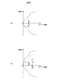
これに対して、第1実施形態の緩衝器1は、ディスクバルブ73の内側シート241側に、ディスクバルブ73の外周側を外側シート93に向けて付勢する付勢ディスク78が設けられているため、付勢ディスク78を設けない場合と比べて、減衰力をハードにすることができる。また、付勢ディスク78を剛性が異なりバネ特性が異なるものに変更することで、減衰力特性をさらに変更することができる。したがって、減衰力特性を容易にチューニングすることができる。例えば、伸側と縮側とで同じディスクバルブ73を用いた場合、付勢ディスク78を設けなければ、図5(a)に示すように伸圧比が同じとなり(A=B)、伸側のディスクバルブ73のみに付勢ディスク78を設けることで、図5(b)に示すように伸側の減衰力を縮側の減衰力もハードにするように伸圧比をチューニングすることができる(A’>A=B)。
On the other hand, the shock absorber 1 of the first embodiment is provided with a biasing disc 78 that biases the outer peripheral side of the disc valve 73 toward the outer seat 93 on the inner seat 241 side of the disc valve 73. Therefore, the damping force can be made harder than in the case where the urging disk 78 is not provided. Moreover, the damping force characteristic can be further changed by changing the biasing disk 78 to one having a different rigidity and a different spring characteristic. Therefore, the damping force characteristic can be easily tuned. For example, when the same disk valve 73 is used for the expansion side and the contraction side, if the urging disk 78 is not provided, the pressure expansion ratio is the same as shown in FIG. By providing the urging disk 78 only in the disk valve 73, the expansion ratio can be tuned so that the expansion side damping force and the compression side damping force are hard as shown in FIG. 5B (A '). > A = B).
また、ディスクバルブ73の外周側を外側シート93に向けて付勢する部材として、内周側がクランプされる板状の付勢ディスク78を用いるため、コスト増を抑制しつつ、付勢ディスク78により安定したバネ力でディスクバルブ73を付勢することができる。
Further, since the plate-shaped biasing disk 78 whose inner peripheral side is clamped is used as a member for biasing the outer peripheral side of the disk valve 73 toward the outer seat 93, the biasing disk 78 suppresses an increase in cost. The disc valve 73 can be biased with a stable spring force.
ここで、第1実施形態において、上記とは逆に、バルブ本体71の筒部81に内周嵌合面107から径方向外方に凹む環状のシール溝を形成し、このシール溝にシール部材を配置して、これらにピストン本体41のシール溝のない嵌合部66を嵌合させても良い。
Here, in the first embodiment, conversely to the above, an annular seal groove that is recessed radially outward from the inner peripheral fitting surface 107 is formed in the cylindrical portion 81 of the valve body 71, and a seal member is formed in the seal groove. And a fitting portion 66 without a seal groove of the piston main body 41 may be fitted thereto.
「第2実施形態」
次に、第2実施形態を主に図6に基づいて第1実施形態との相違部分を中心に説明する。なお、第1実施形態と共通する部位については、同一称呼、同一の符号で表す。
“Second Embodiment”
Next, the second embodiment will be described mainly based on FIG. 6 with a focus on the differences from the first embodiment. In addition, about the site | part which is common in 1st Embodiment, it represents with the same name and the same code | symbol.
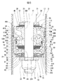
図6に示すように、第2実施形態では、ピストン16Aが第1実施形態のピストン16とは一部異なっている。ピストン16Aは、第1実施形態のピストン本体41をほぼ二分割した形状のいずれも金属製のピストン本体41Aとピストン本体41Bとを有している。つまり、ピストン16Aは、ピストン本体41Aと、ピストン本体41Bと、第1実施形態と同様のバルブ本体71とを有している。
As shown in FIG. 6, in the second embodiment, the piston 16A is partially different from the piston 16 of the first embodiment. The piston 16 </ b> A has a piston main body 41 </ b> A and a piston main body 41 </ b> B, both of which are substantially divided into two parts of the piston main body 41 of the first embodiment. That is, the piston 16A has a piston body 41A, a piston body 41B, and a valve body 71 similar to that of the first embodiment.
ピストン16Aは、いずれも第1実施形態と同様の規制部材37、当接ディスク38、小径ディスク39およびディスクバルブ40を有しており、ディスクバルブ40にピストン本体41Aが重ねられ、ピストン本体41Aのディスクバルブ40とは反対側にピストン本体41Bが重ねられている。
The piston 16A has the same regulating member 37, contact disk 38, small-diameter disk 39 and disk valve 40 as in the first embodiment. The piston body 41A is superimposed on the disk valve 40, and the piston body 41A A piston main body 41 </ b> B is superimposed on the side opposite to the disc valve 40.
ピストン本体41Aは、その径方向の中央に、ピストンロッド21の取付軸部32を嵌合させる嵌合孔50Aが軸方向に貫通するように形成されて円環状をなしている。また、ピストン本体41Aには、径方向の嵌合孔50Aよりも外側にて軸方向に延在する屈曲形状の通路51Aと、径方向の嵌合孔50Aよりも外側にて軸方向に延在する屈曲形状の通路52Aとが形成されている。図6では断面とした関係上一カ所のみ図示しているが、通路51Aおよび通路52Aは、いずれもピストン本体41Aに周方向に複数カ所形成されており、ピストン本体41Aの周方向に交互に配置されている。
The piston main body 41A is formed in an annular shape at the center in the radial direction so that a fitting hole 50A for fitting the mounting shaft portion 32 of the piston rod 21 penetrates in the axial direction. The piston main body 41A has a bent passage 51A extending in the axial direction outside the radial fitting hole 50A, and extends in the axial direction outside the radial fitting hole 50A. A bent-shaped passage 52A is formed. In FIG. 6, only one location is shown because of the cross section, but the passage 51A and the passage 52A are both formed in the piston body 41A in the circumferential direction and are alternately arranged in the circumferential direction of the piston body 41A. Has been.
また、ピストン本体41Aには、軸方向のディスクバルブ40側の端部に、複数の通路51Aを連通させる第1実施形態と同様の環状通路53と、その径方向内側のクランプシート56と、環状通路53の径方向外側の当接シート57とが形成されている。複数の通路52Aは、ディスクバルブ40側の開口部が、ディスクバルブ40とは反対側の開口部よりも径方向外側に位置しており、当接シート57よりも径方向外側に開口している。
Further, the piston body 41A has an annular passage 53 similar to that of the first embodiment in which a plurality of passages 51A are communicated with an end on the disk valve 40 side in the axial direction, a radially inner clamp sheet 56, and an annular shape. A contact sheet 57 radially outside the passage 53 is formed. In the plurality of passages 52A, the opening on the disk valve 40 side is located on the radially outer side than the opening on the side opposite to the disk valve 40, and is opened on the radially outer side than the contact sheet 57. .
また、ピストン本体41Aには、軸方向のディスクバルブ40とは反対側の端部で複数の通路52Aを繋ぐようにピストン本体41Aの全周にわたって環状をなす環状通路54Aが形成されている。環状通路54Aが形成されることで、ピストン本体41Aの軸方向のディスクバルブ40とは反対側の端部には、ピストン本体41Aの径方向において環状通路54Aよりも内側の内側当接部61Aと環状通路54Aよりも外側の外側当接部62Aとがいずれもピストン本体41Aの軸方向に突出して設けられている。複数の通路51Aは、ディスクバルブ40とは反対側の開口部が、ディスクバルブ40側の開口部よりも径方向外側に位置しており、外側当接部62Aよりも径方向外側に開口している。
The piston main body 41A is formed with an annular passage 54A that forms a ring over the entire circumference of the piston main body 41A so as to connect the plurality of passages 52A at the end opposite to the axial disk valve 40. By forming the annular passage 54A, an inner contact portion 61A on the inner side of the annular passage 54A in the radial direction of the piston main body 41A is formed at the end of the piston main body 41A opposite to the disk valve 40 in the axial direction. Both outer contact portions 62A outside the annular passage 54A are provided so as to protrude in the axial direction of the piston main body 41A. In the plurality of passages 51A, the opening on the side opposite to the disk valve 40 is located on the radially outer side than the opening on the disk valve 40 side, and is opened on the radially outer side than the outer contact part 62A. Yes.
ピストン本体41Aは、焼結により成形されるものであり、軸方向の中央に対して両側が同じ形状となっており、表裏の区別がない。つまり、軸方向のいずれの向きでもピストンロッド21に取り付けることができる。
The piston main body 41A is formed by sintering and has the same shape on both sides with respect to the center in the axial direction, so there is no distinction between the front and back sides. That is, it can be attached to the piston rod 21 in any axial direction.
ピストン本体41Bは、その径方向の中央に、ピストンロッド21の取付軸部32を嵌合させる嵌合孔50Bが軸方向に貫通するように形成されて円環状をなしている。また、ピストン本体41Bには、径方向の嵌合孔50Bよりも外側にて軸方向に延在する複数の通路51Bが周方向に等間隔で形成されている。
The piston main body 41B is formed in an annular shape at the center in the radial direction so that a fitting hole 50B for fitting the mounting shaft portion 32 of the piston rod 21 penetrates in the axial direction. The piston main body 41B is formed with a plurality of passages 51B extending in the axial direction outside the radial fitting holes 50B at equal intervals in the circumferential direction.
また、ピストン本体41Bには、軸方向のピストン本体41A側の端部で複数の通路51Bを繋ぐようにピストン本体41Bの全周にわたって環状をなす環状通路53Bが形成されている。環状通路53Bが形成されることで、ピストン本体41Bの軸方向のピストン本体41A側の端部には、ピストン本体41Bの径方向において環状通路53Bよりも内側の内側当接部56Bと環状通路53Bよりも外側の外側当接部57Bとが設けられている。
The piston main body 41B is formed with an annular passage 53B that forms a ring over the entire circumference of the piston main body 41B so as to connect the plurality of passages 51B at the end of the piston main body 41A in the axial direction. By forming the annular passage 53B, the inner abutting portion 56B and the annular passage 53B on the inner side of the annular passage 53B in the radial direction of the piston main body 41B are disposed at the end of the piston body 41B on the piston body 41A side in the axial direction. An outer abutting portion 57B is provided on the outer side.
また、ピストン本体41Bには、軸方向のピストン本体41Aとは反対側の端部に、複数の通路51Bを連通させる第1実施形態と同様の環状通路54と、その径方向内側のクランプシート61と、環状通路54の径方向外側の当接シート62とが形成されている。
Further, the piston body 41B has an annular passage 54 similar to that of the first embodiment in which a plurality of passages 51B are communicated with an end portion opposite to the axial piston body 41A, and a radially inner clamp sheet 61. And an abutting sheet 62 on the radially outer side of the annular passage 54 is formed.
ピストン本体41Aには、その外周部に、摺接部材44が装着される第1実施形態と同様の装着ベース部65が形成されており、ピストン本体41Bには、その外周部に、外周嵌合面67と外周嵌合面67から径方向内方に凹むシール溝68とを有する第1実施形態と同様の嵌合部66が形成されている。嵌合部66は、その外周嵌合面67がピストン本体41Bの径方向における当接シート62よりも外周側に設けられている。嵌合部66のシール溝68には、第1実施形態と同様のシール部材77が配置されている。
The piston main body 41A is formed with a mounting base portion 65 similar to that of the first embodiment in which the sliding contact member 44 is mounted on the outer peripheral portion thereof, and the piston main body 41B has an outer peripheral fitting on the outer peripheral portion thereof. A fitting portion 66 similar to that of the first embodiment having the surface 67 and a seal groove 68 that is recessed radially inward from the outer peripheral fitting surface 67 is formed. As for the fitting part 66, the outer periphery fitting surface 67 is provided in the outer peripheral side rather than the contact sheet 62 in the radial direction of piston main body 41B. A seal member 77 similar to that of the first embodiment is disposed in the seal groove 68 of the fitting portion 66.
ピストン16Aは、いずれも第1実施形態と同様のディスクバルブ42、小径ディスク43、バルブ本体71、ガイドディスク72、ディスクバルブ73、支持ディスク74、付勢ディスク78、当接ディスク75および規制部材76を有している。
The piston 16A has the same disc valve 42, small diameter disc 43, valve main body 71, guide disc 72, disc valve 73, support disc 74, biasing disc 78, contact disc 75, and restricting member 76 as in the first embodiment. have.
ピストン16Aをピストンロッド21に組み付ける場合、ピストンロッド21には、取付軸部32をそれぞれの内側に挿通させた状態で、規制部材37と、当接ディスク38と、小径ディスク39と、ディスクバルブ40と、摺接部材44が設けられたピストン本体41Aと、シール部材77が設けられたピストン本体41Bと、ディスクバルブ42と、小径ディスク43と、バルブ本体71と、ガイドディスク72とが、この順に、軸段部33に重ねられる。その際に、ピストン本体41Aおよびピストン本体41Bは、内側当接部61Aと内側当接部56Bとを全周にわたって当接させ、外側当接部62Aと外側当接部57Bとを全周にわたって当接させることになる。この状態で、環状通路54Aと環状通路53Bとが連通する。また、この状態で、予めシール溝68にシール部材77が配置された状態のピストン本体41Bの嵌合部66にバルブ本体71の筒部81を嵌合させる。
When the piston 16 </ b> A is assembled to the piston rod 21, the regulating member 37, the contact disk 38, the small diameter disk 39, and the disk valve 40 are inserted into the piston rod 21 with the attachment shaft portions 32 inserted into the piston rod 21. The piston main body 41A provided with the sliding contact member 44, the piston main body 41B provided with the seal member 77, the disk valve 42, the small diameter disk 43, the valve main body 71, and the guide disk 72 in this order. The shaft step 33 is overlaid. At that time, the piston main body 41A and the piston main body 41B abut the inner abutting portion 61A and the inner abutting portion 56B over the entire circumference, and contact the outer abutting portion 62A and the outer abutting portion 57B over the entire circumference. Will be in contact. In this state, the annular passage 54A and the annular passage 53B communicate with each other. In this state, the cylinder portion 81 of the valve main body 71 is fitted to the fitting portion 66 of the piston main body 41B in a state where the seal member 77 is previously disposed in the seal groove 68.
また、取付軸部32を内側に挿通させた状態で、ディスクバルブ73がバルブ本体71の外側シート93に重ねられる。さらに、取付軸部32をそれぞれの内側に挿通させた状態で、支持ディスク74、付勢ディスク78、当接ディスク75、規制部材76が、ガイドディスク72およびディスクバルブ73に、この順に、重ねられる。
In addition, the disc valve 73 is overlaid on the outer sheet 93 of the valve body 71 with the mounting shaft portion 32 inserted inward. Further, the support disk 74, the biasing disk 78, the contact disk 75, and the regulating member 76 are stacked on the guide disk 72 and the disk valve 73 in this order with the mounting shaft portion 32 inserted inside each of them. .
このように部品が配置された状態で、規制部材76よりも突出する取付軸部32のオネジ34にナット35が螺合される。これにより、規制部材37と、当接ディスク38と、小径ディスク39と、ディスクバルブ40と、摺接部材44が設けられたピストン本体41Aと、シール部材77が設けられたピストン本体41Bと、ディスクバルブ42と、小径ディスク43と、バルブ本体71と、ガイドディスク72と、支持ディスク74と、付勢ディスク78と、当接ディスク75と、規制部材76とは、それぞれ内周側または全部がピストンロッド21の軸段部33とナット35とに挟持されて軸方向にクランプされる。その際に、ディスクバルブ73は、軸方向にクランプされることはなく、支持ディスク74の内側シート241に当接し、支持ディスク74で押圧されて弾性変形して、その内側にガイドディスク72を嵌合させる。
With the components arranged in this manner, the nut 35 is screwed onto the male screw 34 of the mounting shaft portion 32 that protrudes beyond the regulating member 76. Accordingly, the regulating member 37, the contact disk 38, the small diameter disk 39, the disk valve 40, the piston body 41A provided with the sliding contact member 44, the piston body 41B provided with the seal member 77, the disk The valve 42, the small-diameter disk 43, the valve main body 71, the guide disk 72, the support disk 74, the biasing disk 78, the abutting disk 75, and the regulating member 76 are respectively pistons on the inner peripheral side. It is clamped in the axial direction by being sandwiched between the shaft step portion 33 and the nut 35 of the rod 21. At this time, the disc valve 73 is not clamped in the axial direction, but abuts against the inner sheet 241 of the support disc 74 and is elastically deformed by being pressed by the support disc 74, and the guide disc 72 is fitted inside thereof. Combine.
このように軸方向にクランプされることで、ピストン本体41Aおよびピストン本体41Bは、内側当接部61Aと内側当接部56Bとが全周にわたって隙間なく密着し、外側当接部62Aと外側当接部57Bとが全周にわたって隙間なく密着することになる。言い換えれば、内側当接部61Aと内側当接部56Bとの間が全周にわたって密封され、外側当接部62Aと外側当接部57Bとの間が全周にわたって密封される。つまり、ピストン本体41Aおよびピストン本体41Bの環状通路54A,53Bからの油液の漏れが規制される。
By being clamped in the axial direction in this way, the piston main body 41A and the piston main body 41B have the inner contact portion 61A and the inner contact portion 56B in close contact with each other without any gap, and the outer contact portion 62A and the outer contact portion 62B. The contact portion 57B is in close contact with the entire circumference without any gap. In other words, the space between the inner contact portion 61A and the inner contact portion 56B is sealed over the entire periphery, and the space between the outer contact portion 62A and the outer contact portion 57B is sealed over the entire periphery. That is, the leakage of the oil from the annular passages 54A and 53B of the piston main body 41A and the piston main body 41B is restricted.
このようにしてピストンロッド21に取り付けられた状態のピストン16Aは、嵌合部66と筒部81とが、シール部材77を介して液密的に嵌合し、嵌合部66と筒部81との隙間を介して、ピストン本体41Bとバルブ本体71との間の中間通路108が下室18に連通するのを規制する。また、バルブ本体71の筒部81のテーパ部95がピストン本体41Aの複数の通路51Aの方向に向いている。
In the piston 16 </ b> A attached to the piston rod 21 in this way, the fitting portion 66 and the cylindrical portion 81 are fluid-tightly fitted via the seal member 77, and the fitting portion 66 and the cylindrical portion 81 are fitted. The intermediate passage 108 between the piston main body 41 </ b> B and the valve main body 71 is restricted from communicating with the lower chamber 18 through the clearance. Moreover, the taper part 95 of the cylinder part 81 of the valve body 71 faces the direction of the plurality of passages 51A of the piston body 41A.
ピストン本体41Aの複数の通路51Aおよび環状通路53が、ピストンロッド21およびピストン16が縮み側に移動するときに油液が通過する縮側通路117Aとなっており、この縮側通路117Aに減衰力発生機構111が設けられている。
The plurality of passages 51A and the annular passage 53 of the piston main body 41A constitute a contraction-side passage 117A through which the oil liquid passes when the piston rod 21 and the piston 16 move to the contraction side. A damping force is applied to the contraction-side passage 117A. A generation mechanism 111 is provided.
複数の通路52A、環状通路54A、環状通路53B、複数の通路51B、環状通路54、中間通路108、複数の通路86および環状通路91が、ピストンロッド21およびピストン16が伸び側に移動するときに油液が通過する伸側通路118A(通路)となっており、この伸側通路118Aに減衰力発生機構115が設けられている。
When the plurality of passages 52A, the annular passage 54A, the annular passage 53B, the plurality of passages 51B, the annular passage 54, the intermediate passage 108, the plurality of passages 86, and the annular passage 91 move to the expansion side. It is an extension side passage 118A (passage) through which the oil liquid passes, and a damping force generation mechanism 115 is provided in the extension side passage 118A.
ピストン本体41Aには、伸側通路118Aの一部である複数の通路52Aおよび環状通路54Aがその内部を軸方向に貫通して形成されており、ピストン本体41Bには、伸側通路118Aの一部である環状通路53B、複数の通路51B、環状通路54がその内部を軸方向に貫通して形成されている。
The piston body 41A is formed with a plurality of passages 52A and an annular passage 54A that are part of the extension side passage 118A in the axial direction, and the piston body 41B has one of the extension side passages 118A. An annular passage 53B, a plurality of passages 51B, and an annular passage 54, which are parts, are formed so as to penetrate the inside thereof in the axial direction.
第2実施形態においても 伸び行程では、ピストン速度が極低速のとき、上室17の油液は、伸側通路118Aを構成する複数の通路52A、環状通路54A、環状通路53B、複数の通路51Bおよび環状通路54から、減衰バルブ113を構成するディスクバルブ42を当接シート62に当接させた状態のまま、ディスクバルブ42に形成された固定オリフィス63および伸側通路118Aを構成する中間通路108、複数の通路86および環状通路91を流れ、減衰バルブ114を構成するディスクバルブ73を自身のバネ力および付勢ディスク78のバネ力に抗して外側シート93から離間させながらディスクバルブ73と外側シート93との隙間を介して下室18に流れる。これにより、減衰バルブ114のディスクバルブ73および外側シート93が伸側通路118Aの油液の流れを抑制してバルブ特性の減衰力を発生させる。
Also in the second embodiment, in the extension stroke, when the piston speed is extremely low, the oil liquid in the upper chamber 17 causes the plurality of passages 52A, the annular passages 54A, the annular passages 53B, and the plurality of passages 51B constituting the extension side passage 118A. The annular passage 54 and the intermediate passage 108 constituting the fixed orifice 63 and the extension side passage 118A formed in the disc valve 42 while the disc valve 42 constituting the damping valve 113 is kept in contact with the contact seat 62. The disc valve 73 that flows through the plurality of passages 86 and the annular passage 91 and separates from the outer seat 93 while keeping the disc valve 73 constituting the damping valve 114 away from the outer seat 93 against its own spring force and the spring force of the biasing disc 78. It flows into the lower chamber 18 through a gap with the sheet 93. As a result, the disc valve 73 and the outer seat 93 of the damping valve 114 suppress the flow of the oil liquid in the extension side passage 118A and generate a damping force of the valve characteristic.
また、ピストン速度が上記よりも速くなると、上室17の油液は、複数の通路52A、環状通路54A、環状通路53B、複数の通路51Bおよび環状通路54から、減衰バルブ113を構成するディスクバルブ42を当接シート62から離間させながら、ディスクバルブ42と当接シート62との隙間を介して中間通路108に流れ、中間通路108、複数の通路86および環状通路91から、減衰バルブ114を構成するディスクバルブ73を自身のバネ力および付勢ディスク78のバネ力に抗して外側シート93から離間させながらディスクバルブ73と外側シート93との隙間を介して下室18に流れる。これにより、減衰バルブ113のディスクバルブ42および当接シート62と減衰バルブ114のディスクバルブ73および外側シート93が伸側通路118Aの油液の流れを抑制してバルブ特性の減衰力を発生させる。
Further, when the piston speed becomes faster than the above, the fluid in the upper chamber 17 causes the disk valve constituting the damping valve 113 from the plurality of passages 52A, the annular passage 54A, the annular passage 53B, the plurality of passages 51B, and the annular passage 54. 42 is separated from the contact sheet 62 and flows into the intermediate passage 108 through the gap between the disc valve 42 and the contact sheet 62, and the damping valve 114 is constituted by the intermediate passage 108, the plurality of passages 86 and the annular passage 91. The disc valve 73 to flow flows into the lower chamber 18 through a gap between the disc valve 73 and the outer seat 93 while being separated from the outer seat 93 against the spring force of the own disc and the biasing disc 78. As a result, the disc valve 42 and the abutting seat 62 of the damping valve 113 and the disc valve 73 and the outer seat 93 of the damping valve 114 suppress the flow of the oil liquid in the extension side passage 118A to generate a damping force of the valve characteristics.
縮み行程では、下室18の油液が、縮側通路117Aを介して上室17側に流れる。ピストン速度が低速のとき、下室18の油液は、縮側通路117Aから減衰力発生機構111を構成するディスクバルブ40を当接シート57に当接させた状態のまま、ディスクバルブ40に形成された固定オリフィス58を介して上室17側に流れ、減衰力発生機構111の固定オリフィス58が縮側通路117Aの油液の流れを抑制してオリフィス特性の減衰力を発生させる。また、ピストン速度が上昇すると、下室18から縮側通路117Aに導入された油液が、ディスクバルブ40を開きながらディスクバルブ40と当接シート57との間を通って上室17に流れ、減衰力発生機構111のディスクバルブ40および当接シート57が縮側通路117Aの油液の流れを抑制してバルブ特性の減衰力を発生させる。
In the contraction stroke, the oil in the lower chamber 18 flows to the upper chamber 17 side through the contraction side passage 117A. When the piston speed is low, the oil in the lower chamber 18 is formed in the disc valve 40 while the disc valve 40 constituting the damping force generation mechanism 111 is in contact with the contact seat 57 from the contraction side passage 117A. The fixed orifice 58 of the damping force generation mechanism 111 suppresses the flow of the oil liquid in the contraction side passage 117A and generates the damping force of the orifice characteristic. Further, when the piston speed is increased, the oil introduced from the lower chamber 18 into the contraction side passage 117A flows into the upper chamber 17 through the space between the disc valve 40 and the contact seat 57 while opening the disc valve 40, The disc valve 40 and the contact sheet 57 of the damping force generation mechanism 111 suppress the flow of the oil liquid in the contraction side passage 117A and generate a damping force of the valve characteristic.
第2実施形態においては、第1実施形態と同様の効果を奏することができ、加えて、一のピストン本体41Bを、通路51Bの断面積がこれとは異なる他のピストン本体41Bに交換するのみで、減衰バルブ114による減衰力特性を変更することができ、ピストン本体41Aは減衰力特性の変更時も共用できる。
In the second embodiment, the same effects as those of the first embodiment can be obtained. In addition, one piston main body 41B is simply replaced with another piston main body 41B having a different cross-sectional area of the passage 51B. Thus, the damping force characteristic by the damping valve 114 can be changed, and the piston body 41A can be shared when the damping force characteristic is changed.
「第3実施形態」
次に、第3実施形態を主に図7に基づいて第1,第2実施形態との相違部分を中心に説明する。なお、第1,第2実施形態と共通する部位については、同一称呼、同一の符号で表す。
“Third Embodiment”
Next, the third embodiment will be described mainly on the basis of FIG. 7, focusing on the differences from the first and second embodiments. In addition, about the site | part which is common in 1st, 2nd embodiment, it represents with the same name and the same code | symbol.
図7に示すように、第3実施形態のピストン16Cは、バルブ本体71Cを有している。バルブ本体71Cには、その径方向の中央に、ピストンロッド21の取付軸部32を嵌合させる嵌合孔85Cが軸方向に貫通するように形成されている。バルブ本体71Cは、ピストンロッド21の取付軸部32に嵌合されて軸段部33に当接している。バルブ本体71Cには、嵌合孔85Cよりも径方向外側に、軸方向に貫通する複数の通路86Cが形成されている。複数の通路86Cは、バルブ本体71Cにその周方向に等間隔で形成されている。バルブ本体71Cには、軸方向の軸段部33とは反対側に、複数の通路86Cを連通させるようにバルブ本体71Cの全周にわたって環状をなす環状通路91Cが形成されている。
As shown in FIG. 7, the piston 16C of the third embodiment has a valve body 71C. A fitting hole 85C for fitting the mounting shaft portion 32 of the piston rod 21 is formed in the valve body 71C in the radial direction so as to penetrate in the axial direction. The valve main body 71 </ b> C is fitted to the mounting shaft portion 32 of the piston rod 21 and is in contact with the shaft step portion 33. The valve body 71C is formed with a plurality of passages 86C penetrating in the axial direction on the radially outer side than the fitting hole 85C. The plurality of passages 86C are formed in the valve body 71C at equal intervals in the circumferential direction. In the valve main body 71C, an annular passage 91C is formed on the opposite side of the shaft step portion 33 in the axial direction so as to form a ring over the entire circumference of the valve main body 71C so as to communicate the plurality of passages 86C.
環状通路91Cが形成されることで、バルブ本体71Cの軸方向の軸段部33とは反対側の端部に、第1実施形態と同様のクランプシート92および外側シート93が形成されている。また、バルブ本体71Cには、外側シート93の外周側に、第1実施形態と同様の拘束突起211が形成されており、拘束突起211と外側シート93との間に、第1実施形態と同様の凹部212が形成されている。
By forming the annular passage 91C, a clamp sheet 92 and an outer sheet 93 similar to those of the first embodiment are formed at the end of the valve body 71C opposite to the axial step 33 in the axial direction. Further, the valve main body 71 </ b> C is formed with a restraining projection 211 similar to that of the first embodiment on the outer peripheral side of the outer seat 93, and between the restraining projection 211 and the outer seat 93, similarly to the first embodiment. The recess 212 is formed.
ピストン16Cには、第1実施形態と同様のガイドディスク72がバルブ本体71Cのクランプシート92に当接して設けられており、第1実施形態と同様の支持ディスク74がガイドディスク72に当接して設けられている。また、ピストン16Cには、第1実施形態と同様の付勢ディスク78がベース板部231において支持ディスク74に当接して設けられており、第1実施形態と同様の当接ディスク75が付勢ディスク78のベース板部231に当接して設けられている。また、ピストン16Cには、第1実施形態と同様のディスクバルブ73が、支持ディスク74とバルブ本体71Cとの間で、ガイドディスク72の径方向外側に配置されている。
The piston 16C is provided with a guide disk 72 similar to that of the first embodiment in contact with the clamp sheet 92 of the valve body 71C, and a support disk 74 similar to that of the first embodiment is in contact with the guide disk 72. Is provided. The piston 16C is provided with an urging disk 78 similar to that of the first embodiment in contact with the support disk 74 at the base plate portion 231, and the urging disk 75 similar to that of the first embodiment is urged. It is provided in contact with the base plate portion 231 of the disk 78. In addition, a disk valve 73 similar to that of the first embodiment is disposed on the piston 16C between the support disk 74 and the valve body 71C on the radially outer side of the guide disk 72.
第3実施形態においても、ディスクバルブ73は、変形しない自然状態にあるとき平板状であり、図8に示すようにピストン16Cに組み付けられた状態でテーパ状に弾性変形する。また、ピストン16Cに組み付けられた状態で、付勢ディスク78は、内周側のベース板部231において軸方向にクランプされ、すべての脚板部232が弾性変形して、すべての当接板部233がディスクバルブ73の外周側に当接する。これにより、付勢ディスク78は、ディスクバルブ73の軸方向の内側シート241側の面の外周側に当接して、この外周側を外側シート93に向けて付勢する。第3実施形態においても、ディスクバルブ73は、その内周側が、両面側からクランプされずに片面側のみ支持ディスク74に支持される単純支持構造となっている。
Also in the third embodiment, the disk valve 73 has a flat plate shape when in a natural state where it does not deform, and elastically deforms in a tapered shape in a state assembled to the piston 16C as shown in FIG. Further, the biasing disc 78 is clamped in the axial direction at the base plate portion 231 on the inner peripheral side in a state assembled to the piston 16C, and all the leg plate portions 232 are elastically deformed, so that all the contact plate portions 233 are fixed. Comes into contact with the outer peripheral side of the disk valve 73. As a result, the urging disc 78 abuts on the outer peripheral side of the surface on the inner seat 241 side in the axial direction of the disc valve 73 and urges the outer peripheral side toward the outer seat 93. Also in the third embodiment, the disk valve 73 has a simple support structure in which the inner peripheral side is supported by the support disk 74 only on one side without being clamped from both sides.
ピストン16Cは、当接ディスク75に当接する小径ディスク300と、小径ディスク300に当接し小径ディスク300とは反対側に径方向に延びる通路溝301が形成された通路形成部材302と、底部304および筒部305を有する有底筒状をなして底部304で通路形成部材302に当接し筒部305でバルブ本体71Cに嵌合するケース部材306と、バルブ本体71Cとケース部材306の筒部305との間をシールするシール部材308とを有している。ピストンロッド21の取付軸部32には、通路形成部材302の通路溝301に連通する通路穴310が形成されている。通路穴310および通路溝301で、バルブ本体71Cとケース部材306との間の室311が下室18に常時連通する。
The piston 16C includes a small-diameter disk 300 that abuts against the abutting disk 75, a passage-forming member 302 that is in contact with the small-diameter disk 300 and has a passage groove 301 that extends in the radial direction on the opposite side of the small-diameter disk 300, A case member 306 which has a bottomed cylindrical shape having a cylindrical portion 305 and abuts against the passage forming member 302 at the bottom portion 304 and fits to the valve main body 71C at the cylindrical portion 305; And a seal member 308 for sealing between the two. A passage hole 310 communicating with the passage groove 301 of the passage forming member 302 is formed in the mounting shaft portion 32 of the piston rod 21. Through the passage hole 310 and the passage groove 301, the chamber 311 between the valve main body 71 </ b> C and the case member 306 always communicates with the lower chamber 18.
ケース部材306の底部304には、いずれも第1実施形態と同様の規制部材37、当接ディスク38、小径ディスク39およびディスクバルブ40がこの順に重ねられ、ディスクバルブ40に、第2実施形態と同様のピストン本体41A、第1実施形態と同様のディスクバルブ42、第1実施形態と同様の小径ディスク43、当接ディスク313および第1実施形態と同様の規制部材76がこの順に重ねられている。そして、ピストンロッド21の取付軸部32の規制部材76よりも突出するオネジ34にナット35が螺合されている。ディスクバルブ42は、ピストン本体41Aの内側当接部61Aおよび外側当接部62Aに当接して環状通路54Aおよび通路52Aを閉塞する。
On the bottom 304 of the case member 306, the same restricting member 37, contact disk 38, small-diameter disk 39 and disk valve 40 are stacked in this order as in the first embodiment, and the disk valve 40 is overlapped with the second embodiment. A similar piston main body 41A, a disk valve 42 similar to the first embodiment, a small diameter disk 43 similar to the first embodiment, a contact disk 313, and a regulating member 76 similar to the first embodiment are stacked in this order. . A nut 35 is screwed onto the male screw 34 that protrudes beyond the regulating member 76 of the mounting shaft portion 32 of the piston rod 21. The disk valve 42 contacts the inner contact portion 61A and the outer contact portion 62A of the piston body 41A to close the annular passage 54A and the passage 52A.
ピストン16Cをピストンロッド21に組み付ける場合、ピストンロッド21には、バルブ本体71Cと、ガイドディスク72とが、この順に、軸段部33に重ねられ、ディスクバルブ73がバルブ本体71Cの外側シート93にさらに重ねられる。加えて、支持ディスク74、付勢ディスク78、当接ディスク75、小径ディスク300、通路形成部材302が、ディスクバルブ73に、この順に重ねられる。そして、ケース部材306がその筒部305を、シール部材308を保持した状態のバルブ本体71Cに嵌合させて、底部304において通路形成部材302に重ねられる。さらに、ケース部材306の底部304に、規制部材37、当接ディスク38、小径ディスク39、ディスクバルブ40、ピストン本体41A、ディスクバルブ42、小径ディスク43、当接ディスク313および規制部材76がこの順に重ねられる。
When the piston 16C is assembled to the piston rod 21, a valve body 71C and a guide disk 72 are superimposed on the shaft step portion 33 in this order on the piston rod 21, and the disk valve 73 is placed on the outer seat 93 of the valve body 71C. It is further stacked. In addition, the support disk 74, the urging disk 78, the contact disk 75, the small diameter disk 300, and the passage forming member 302 are stacked on the disk valve 73 in this order. Then, the case member 306 is fitted on the passage forming member 302 at the bottom portion 304 by fitting the cylindrical portion 305 to the valve main body 71 </ b> C holding the seal member 308. Further, a regulating member 37, a contact disk 38, a small diameter disk 39, a disk valve 40, a piston main body 41A, a disk valve 42, a small diameter disk 43, a contact disk 313, and a regulation member 76 are arranged in this order on the bottom 304 of the case member 306. Overlaid.
このように部品が配置された状態で、規制部材76よりも突出する取付軸部32のオネジ34にナット35が螺合される。これにより、バルブ本体71C、ガイドディスク72、支持ディスク74、付勢ディスク78、当接ディスク75、小径ディスク300、通路形成部材302、ケース部材306の底部304、規制部材37、当接ディスク38、小径ディスク39、ディスクバルブ40、ピストン本体41A、ディスクバルブ42、小径ディスク43、当接ディスク313および規制部材76が、それぞれ内周側または全部がピストンロッド21の軸段部33とナット35とに挟持されて軸方向にクランプされる。その際に、ディスクバルブ73は、軸方向にクランプされることはなく、支持ディスク74の内側シート241で押圧されて弾性変形し、その内側にガイドディスク72を配置する状態となる。
With the components arranged in this manner, the nut 35 is screwed onto the male screw 34 of the mounting shaft portion 32 that protrudes beyond the regulating member 76. Accordingly, the valve main body 71C, the guide disk 72, the support disk 74, the urging disk 78, the contact disk 75, the small diameter disk 300, the passage forming member 302, the bottom 304 of the case member 306, the regulating member 37, the contact disk 38, The small-diameter disk 39, the disk valve 40, the piston main body 41A, the disk valve 42, the small-diameter disk 43, the contact disk 313, and the regulating member 76 are respectively connected to the shaft step portion 33 of the piston rod 21 and the nut 35. It is clamped and clamped in the axial direction. At that time, the disk valve 73 is not clamped in the axial direction, is pressed by the inner sheet 241 of the support disk 74 and elastically deforms, and the guide disk 72 is disposed inside thereof.
第2実施形態と同様、ピストン本体41Aの複数の通路51Aおよび環状通路53が、ピストンロッド21およびピストン16Cが縮み側に移動するときに油液が通過する縮側通路117Aとなっており、この縮側通路117Aに減衰力発生機構111が設けられている。
Similar to the second embodiment, the plurality of passages 51A and the annular passage 53 of the piston main body 41A are the compression-side passages 117A through which oil passes when the piston rod 21 and the piston 16C move to the contraction side. A damping force generation mechanism 111 is provided in the compression side passage 117A.
複数の通路52Aおよび環状通路54Aが、ピストンロッド21およびピストン16Cが伸び側に移動するときに油液が通過する第1の伸側通路118Cとなっている。そして、環状通路54Aの径方向両側の内側当接部61Aおよび外側当接部62Aと、環状通路54Aを閉塞するように内側当接部61Aおよび外側当接部62Aに着座可能に載置されたディスクバルブ42とが、第1の伸側通路118Cを開閉する減衰バルブ113Cを構成している。
The plurality of passages 52A and the annular passage 54A serve as a first extension side passage 118C through which oil passes when the piston rod 21 and the piston 16C move to the extension side. Then, the inner abutment portion 61A and the outer abutment portion 62A on both sides in the radial direction of the annular passage 54A and the inner abutment portion 61A and the outer abutment portion 62A are seated so as to close the annular passage 54A. The disc valve 42 constitutes a damping valve 113C that opens and closes the first extension side passage 118C.
バルブ本体71Cの通路86Cおよび環状通路91C、室311、通路溝301および通路穴310が、ピストンロッド21およびピストン16Cが伸び側に移動するときに油液が通過する第2の伸側通路320(通路)となっている。そして、環状通路91Cの径方向外側の外側シート93と、環状通路91Cを閉塞するように外側シート93に着座可能に載置されたディスクバルブ73と、環状通路91Cを閉塞するようにディスクバルブ73に当接する支持ディスク74とが、第2の伸側通路320を開閉する減衰バルブ114Cを構成している。外側シート93を含むバルブ本体71Cがこの減衰バルブ114Cの本体部分となっている。そして、減衰バルブ113Cおよび減衰バルブ114Cが、伸び側の減衰力発生機構115Cを構成している。
The passage 86C and the annular passage 91C, the chamber 311, the passage groove 301, and the passage hole 310 of the valve main body 71C are provided with a second extension side passage 320 (through which oil passes when the piston rod 21 and the piston 16C move to the extension side. Aisle). Then, the outer side seat 93 radially outside the annular passage 91C, the disc valve 73 placed so as to be seated on the outer seat 93 so as to close the annular passage 91C, and the disc valve 73 so as to close the annular passage 91C. The support disk 74 that is in contact with the above constitutes a damping valve 114 </ b> C that opens and closes the second extension side passage 320. A valve main body 71C including the outer seat 93 is a main body portion of the damping valve 114C. The damping valve 113C and the damping valve 114C constitute an extension-side damping force generation mechanism 115C.
上記実施形態は、複筒式の油圧緩衝器に本発明を用いた例を示したが、これに限らず、外筒をなくしシリンダ内の下室の上室とは反対側に摺動可能な区画体でガス室を形成するモノチューブ式の油圧緩衝器に用いてもよく、あらゆる緩衝器に用いることができる。勿論、上記した縮み側の減衰力発生機構111に本発明を適用したり、上記したベースバルブ25に本発明を適用することも可能である。また、シリンダ2の外部にシリンダ2内と連通する油通路を設け、この油通路に減衰力発生機構を設ける場合にも適用可能である。また、上記実施形態では、油圧緩衝器を例に示したが、流体として水や空気を用いることもできる。
In the above embodiment, an example in which the present invention is applied to a double cylinder type hydraulic shock absorber has been shown. You may use for the monotube type hydraulic shock absorber which forms a gas chamber with a division body, and can use it for all shock absorbers. Of course, it is possible to apply the present invention to the above-described contraction-side damping force generating mechanism 111 or to apply the present invention to the above-described base valve 25. The present invention is also applicable to the case where an oil passage communicating with the inside of the cylinder 2 is provided outside the cylinder 2 and a damping force generating mechanism is provided in the oil passage. Moreover, in the said embodiment, although the hydraulic shock absorber was shown as an example, water and air can also be used as a fluid.
以上に述べた実施形態は、作動流体が封入されたシリンダと、前記シリンダ内に摺動可能に設けられ、該シリンダ内を区画するピストンと、前記ピストンに一端が接続され前記シリンダの外部へ延出されたピストンロッドと、前記ピストンの摺動により作動流体が流れる通路と、前記通路の一部に設けられ作動流体の流れを抑制して減衰力を発生させる減衰力発生機構と、を備え、前記減衰力発生機構は、前記通路がその内部を貫通するバルブ本体と、前記通路の一端開口を囲む環状の外側シートと、前記外側シートに一側面が着座可能に載置される環状のディスクバルブと、前記ディスクバルブの他側面に当接可能な前記外側シートよりも小径の内側シートと、を有し、前記ディスクバルブの前記他側面側には、該ディスクバルブの外周側を前記外側シートに向けて付勢する付勢手段が設けられている。このように、ディスクバルブの他側面側に、ディスクバルブの外周側を外側シートに向けて付勢する付勢手段が設けられているため、付勢手段を設けない場合と比べて、減衰力をハードにすることができる。また、付勢手段を特性が異なるものに変更することで、減衰力特性をさらに変更することができる。したがって、減衰力特性を容易にチューニングすることができる。
In the embodiment described above, a cylinder in which a working fluid is sealed, a piston slidably provided in the cylinder, and one end connected to the piston and extending to the outside of the cylinder are provided. A piston rod that is taken out, a passage through which the working fluid flows by sliding of the piston, and a damping force generation mechanism that is provided in a part of the passage and suppresses the flow of the working fluid to generate a damping force, The damping force generating mechanism includes a valve main body through which the passage passes, an annular outer seat surrounding one end opening of the passage, and an annular disc valve mounted on one side of the outer seat so as to be seated. And an inner seat having a smaller diameter than the outer seat that can come into contact with the other side surface of the disc valve, and the outer side of the disc valve is disposed on the other side surface of the disc valve. Biasing means for urging said outer sheet is provided. As described above, since the urging means for urging the outer peripheral side of the disc valve toward the outer seat is provided on the other side surface of the disc valve, the damping force is reduced as compared with the case where no urging means is provided. Can be hard. Further, the damping force characteristic can be further changed by changing the biasing means to one having a different characteristic. Therefore, the damping force characteristic can be easily tuned.
また、前記付勢手段は板状であって、内周側がクランプされているため、コスト増を抑制しつつ、付勢手段により安定したバネ力でディスクバルブを付勢することができる。
Further, since the biasing means is plate-shaped and the inner peripheral side is clamped, the disk valve can be biased with a stable spring force by the biasing means while suppressing an increase in cost.