JP2017213065A - Plug-in fitting - Google Patents
Plug-in fitting Download PDFInfo
- Publication number
- JP2017213065A JP2017213065A JP2016107435A JP2016107435A JP2017213065A JP 2017213065 A JP2017213065 A JP 2017213065A JP 2016107435 A JP2016107435 A JP 2016107435A JP 2016107435 A JP2016107435 A JP 2016107435A JP 2017213065 A JP2017213065 A JP 2017213065A
- Authority
- JP
- Japan
- Prior art keywords
- fitting
- metal fitting
- ring
- push ring
- protective band
- Prior art date
- Legal status (The legal status is an assumption and is not a legal conclusion. Google has not performed a legal analysis and makes no representation as to the accuracy of the status listed.)
- Pending
Links
- 230000008878 coupling Effects 0.000 claims abstract description 73
- 238000010168 coupling process Methods 0.000 claims abstract description 73
- 238000005859 coupling reaction Methods 0.000 claims abstract description 73
- 125000006850 spacer group Chemical group 0.000 claims abstract description 70
- 210000000078 claw Anatomy 0.000 claims abstract description 55
- 229910052751 metal Inorganic materials 0.000 claims description 188
- 239000002184 metal Substances 0.000 claims description 188
- 230000001681 protective effect Effects 0.000 claims description 68
- 230000002093 peripheral effect Effects 0.000 claims description 58
- 238000003780 insertion Methods 0.000 claims description 30
- 230000037431 insertion Effects 0.000 claims description 30
- 239000013013 elastic material Substances 0.000 claims description 3
- 230000000694 effects Effects 0.000 description 7
- 229910000838 Al alloy Inorganic materials 0.000 description 6
- 229910000881 Cu alloy Inorganic materials 0.000 description 6
- 238000005266 casting Methods 0.000 description 6
- 239000007769 metal material Substances 0.000 description 6
- 235000017166 Bambusa arundinacea Nutrition 0.000 description 4
- 235000017491 Bambusa tulda Nutrition 0.000 description 4
- 241001330002 Bambuseae Species 0.000 description 4
- 235000015334 Phyllostachys viridis Nutrition 0.000 description 4
- 239000011425 bamboo Substances 0.000 description 4
- 238000000034 method Methods 0.000 description 4
- 238000012856 packing Methods 0.000 description 4
- 239000004744 fabric Substances 0.000 description 2
- 238000012986 modification Methods 0.000 description 2
- 230000004048 modification Effects 0.000 description 2
- 238000007789 sealing Methods 0.000 description 2
- 229920003051 synthetic elastomer Polymers 0.000 description 2
- 239000005061 synthetic rubber Substances 0.000 description 2
- XLYOFNOQVPJJNP-UHFFFAOYSA-N water Substances O XLYOFNOQVPJJNP-UHFFFAOYSA-N 0.000 description 2
- 239000000463 material Substances 0.000 description 1
- 235000005282 vitamin D3 Nutrition 0.000 description 1
- 239000011647 vitamin D3 Substances 0.000 description 1
Images








Landscapes
- Fire-Extinguishing By Fire Departments, And Fire-Extinguishing Equipment And Control Thereof (AREA)
- Quick-Acting Or Multi-Walled Pipe Joints (AREA)
Abstract
Description
本発明は、例えば、消火活動に使用される消防用ホース同士を着脱自在に結合する受け金具及び差し金具から成る差込み式の結合金具の改良に係り、特に、結合金具により結合した消防用ホースを引きずったときや消防用ホースの運搬時等に結合金具に外力が作用しても、受け金具と差し金具の結合が解除されるのを防止することができると共に、既存の差込み式の結合金具にも容易に適用することができる差込み式の結合金具に関するものである。 The present invention relates to an improvement of a plug-in type coupling fitting comprising, for example, a receiving fitting and a fitting for releasably coupling fire hoses used for fire fighting activities, and in particular, a fire hose joined by a coupling fitting. Even if an external force is applied to the fitting when dragged or when carrying a fire hose, it is possible to prevent the coupling between the catch and the fitting from being released, and to the existing plug-in type fitting. The present invention also relates to a plug-in type fitting that can be easily applied.
一般に、消防隊による消火活動においては、消防隊員が消防車から火災位置へ向って複数の消防用ホースを引き伸ばし、各消防用ホース同士を差込み式の結合金具により結合して消火活動を行うようにしている。 In general, in fire fighting activities by fire brigades, fire fighters should extend a plurality of fire hoses from the fire engine to the fire location, and connect the fire hoses with plug-in couplings to perform fire fighting activities. ing.
従来、消防用ホース同士を結合する差込み式の結合金具としては、消防用ホースの一端部に結合された受け金具と、別の消防用ホースの一端部に結合され、前記受け金具に着脱自在に結合される差し金具とから成る町野式(登録商標)の結合金具が広く利用されている。この結合金具は、消防用ホース同士の結合及び結合解除を簡単且つ容易に行え、操作性に極めて優れている。 Conventionally, as a plug-in type fitting for joining fire hoses to each other, it can be attached to one end of a fire hose and one end of another fire hose so that it can be attached to and detached from the catch. A Machino-type (registered trademark) coupling fitting comprising a fitting to be joined is widely used. This coupling metal fitting can be easily and easily coupled and released from the fire hoses, and is extremely excellent in operability.
図15は従来の差込み式の結合金具を用いて消防用ホースH同士を結合した状態を示すものであり、前記差込み式の結合金具は、消防用ホースHの一端部に結合した受け金具20と、別の消防用ホースHの一端部に結合した差し金具21とから成る。
FIG. 15 shows a state in which the fire hoses H are coupled to each other using a conventional plug-in coupling bracket, and the plug-in coupling bracket includes a receiving
即ち、前記受け金具20は、図15に示す如く、消防用ホースHの一端部に挿入される外周面が竹の子状に形成されたホース結合筒部22a及びホース結合筒部22aに連設された筒状の受け口部22bを有する受け金具本体22と、受け金具本体22の受け口部22bの外周面に螺着された筒状の締め輪23と、締め輪23内に嵌合された環状の爪座24と、爪座24に等角度ごとに配設され、爪座24の内方へ突出可能な円弧状の複数の爪25と、締め輪23と各爪25との間に介設され、各爪25を内方へ附勢する複数の板バネ26と、受け金具本体22内に装着されたシール用の環状パッキン27と、締め輪23の外周面に嵌合された環状の保護バンド28とを備えている。
That is, as shown in FIG. 15, the
一方、前記差し金具21は、図15に示す如く、別の消防用ホースHの一端部に挿入される外周面が竹の子状に形成されたホース結合筒部29a及びホース結合筒部29aに連設されて先端部外周面に受け金具20の爪25に係止される環状突部29cを形成した差込み筒部29bを有する差し金具本体29と、差し金具本体29の外周面に軸線方向へスライド自在に外嵌され、先端部が受け金具20内に押し込まれて受け金具20の各爪25と差し金具本体22の環状突部29cとの係止を外すと共に、基端部に操作用の鍔部30aを形成した筒状の押し輪30と、差し金具本体29の外周面に嵌められ、押し輪30を抜け止めする止め輪31とを備えている。
On the other hand, as shown in FIG. 15, the
そして、前記受け金具20及び差し金具21は、受け金具本体22のホース結合筒部22a及び差し金具本体29のホース結合筒部29aを各消防用ホースHの一端部にそれぞれ挿入し、消防用ホースHの端部外周面に筒状の保護布(図示省略)及び筒状の金属製のかしめ用リング32を順次嵌合し、前記かしめ用リング32をかしめ機でかしめることによって、消防用ホースHの一端部に結合されている。
And the said metal fitting 20 and the metal fitting 21 insert the hose
ところで、従来の差込み式の結合金具は、受け金具20と差し金具21の結合及び結合解除を簡単且つ容易に行える反面、差し金具21の押し輪30が差し金具本体29に対してスライド自在なフリーの状態になっているため、図16に示す如く、消防用ホースHを引きずったときや消防用ホースHの運搬時等に、押し輪30が地面等との外部接触により受け金具20と差し金具21の結合を解除する方向へスライドし、受け金具20と差し金具21の結合が簡単に解除されてしまうと言う問題があった。
特に、消火活動時においては、消防隊員が消防用ホースHを引きずりながら消火活動を行うため、受け金具20と差し金具21の結合が解除され易い。
By the way, the conventional insertion-type coupling fitting can easily and easily couple and release the coupling fitting 20 and the
In particular, during a fire fighting operation, the fire brigade member performs the fire fighting activity while dragging the fire hose H, so that the coupling between the metal fitting 20 and the
また、消火活動中に消防隊員の操作ミスにより受け金具20と差し金具21が不用意に結合解除されることもあった。
In addition, the metal fitting 20 and the
このように、消火活動中に結合金具の受け金具20と差し金具21の結合が解除されると、送水が中断されて消火活動に支障を来たすだけでなく、結合が外れた消防用ホースHの一端部が水圧により暴れ回り、操作者本人や周囲の人に危害を加えることもあった。
As described above, when the coupling between the metal fitting 20 and the
一方、消防用の差込み式の結合金具においては、受け金具と差し金具の結合が簡単に解除されないようにした差込み式の結合金具が開発されている(例えば、特許文献1及び特許文献2参照)。
On the other hand, in the plug-in type metal fittings for fire fighting, plug-in type metal fittings have been developed so that the coupling between the metal fittings and the metal fittings is not easily released (see, for example,
即ち、前記差込み式の結合金具は、図示していないが、差し金具の差し金具本体の外周面と押し輪の内周面にそれぞれ環状の滑り止め溝を形成し、環状の滑り止め溝により押し輪の不用意なスライドを防止したり、或いは、差し金具の差し金具本体の外周面に形成した溝状の堰止め部と、押し輪の内周面に突出して前記堰止め部に嵌る突部とにより押し輪の不用意なスライドを防止したりするようにしている。 That is, although not shown in the drawing, the insertion-type coupling metal fitting is formed with an annular non-slip groove on the outer peripheral surface of the metal fitting body and the inner peripheral surface of the push ring, and is pushed by the annular non-slip groove. A groove-shaped damming portion formed on the outer peripheral surface of the metal fitting body of the metal fitting, and a protrusion that protrudes from the inner peripheral surface of the push ring and fits into the damming portion. This prevents accidental sliding of the push ring.
しかしながら、前記各差込み式の結合金具は、差し金具本体の外周面と押し輪の内周面との間にクリアランスが形成されていると共に、環状の滑り止め溝や溝状の堰止め部が比較的浅く形成されているため、押し輪に大きな外力が作用したときに、押し輪が簡単にスライドしてしまい、受け金具と差し金具の結合が簡単に解除されてしまうことがあり、結合金具の外力による結合解除の問題を完全に解決することは困難であった。 However, each of the insertion-type coupling brackets has a clearance formed between the outer peripheral surface of the metal fitting body and the inner peripheral surface of the push ring, and an annular non-slip groove and a groove-shaped weir portion are compared. Therefore, when a large external force is applied to the push ring, the push ring can easily slide, and the coupling between the bracket and the fitting can be easily released. It was difficult to completely solve the problem of uncoupling by external force.
本発明は、このような問題点に鑑みて為されたものであり、その目的は、受け金具及び差し金具から成る差込み式の結合金具により結合した消防用ホースを引きずったときや消防用ホースの運搬時等に結合金具に外力が作用しても、受け金具と差し金具の結合が解除されるのを防止することができると共に、既存の差込み式の結合金具にも容易に適用することができるようにした差込み式の結合金具を提供することにある。 The present invention has been made in view of such problems, and its purpose is to drag a fire hose joined by a plug-in joint metal fitting made of a receiving metal fitting and a metal fitting, or for a fire hose. Even when an external force is applied to the coupling bracket during transportation, it is possible to prevent the coupling between the receiving bracket and the insertion bracket from being released, and it can be easily applied to an existing plug-in coupling bracket. An object of the present invention is to provide a plug-in type fitting.
本発明に係る差込み式の結合金具は、筒状の受け金具本体と、受け金具本体の先端部に設けた筒状の締め輪と、締め輪内に嵌合された環状の爪座と、爪座に等角度ごとに配設され、爪座の内方へ突出可能な複数の爪と、各爪を爪座の内方へ付勢する複数の板バネと、締め輪の外周面に嵌合された弾性材製の環状の保護バンドとを備えた受け金具と、先端部が前記受け金具内に挿入されて受け金具の各爪に係止される筒状の差し金具本体と、差し金具本体の外周面に回転自在且つスライド自在に嵌合され、先端部が受け金具内に押し込まれて受け金具の各爪と差し金具本体との係止を外すと共に、基端部に操作用の鍔部を形成した筒状の押し輪とを備えた差し金具とから成る差込み式の結合金具において、前記受け金具の保護バンドは、押し輪の鍔部に当接して押し輪が受け金具の各爪と差し金具本体との係止を外す位置まで受け金具内へ押し込まれるのを阻止するスペーサ部を備え、また、前記差し金具の押し輪の鍔部は、押し輪を回転させたときに保護バンドのスペーサ部に合致してスペーサ部が通過可能な切欠き部を備えていることに特徴がある。 The insertion-type coupling metal fitting according to the present invention includes a cylindrical receiving metal body, a cylindrical fastening ring provided at the tip of the receiving metal body, an annular claw seat fitted in the fastening ring, and a claw Fits multiple claws that are arranged at equal angles on the seat and can project inward of the claw seat, multiple leaf springs that bias each claw toward the inside of the claw seat, and the outer peripheral surface of the ring A receiving metal fitting provided with an annular protective band made of elastic material, a cylindrical insertion metal fitting body whose tip is inserted into the receiving metal fitting and locked to each claw of the receiving metal fitting, and the insertion metal fitting body It is fitted to the outer peripheral surface of the bracket so that it can rotate and slide freely. In the insertion-type coupling fitting comprising a fitting provided with a cylindrical push ring formed with a protective ring of the receiving fitting, A spacer portion is provided to contact the collar portion and prevent the push ring from being pushed into the catch metal to a position where the catch of each catch of the catch metal and the metal fitting body is released. The collar portion is characterized in that it includes a notch portion that matches the spacer portion of the protective band and allows the spacer portion to pass when the push ring is rotated.
前記保護バンドのスペーサ部の内周面を、押し輪の外周面に当接させて押し輪の不用意な回転を阻止する回転止め摩擦面とすることが好ましい。 It is preferable that the inner peripheral surface of the spacer portion of the protective band is a non-rotating friction surface that abuts the outer peripheral surface of the push ring to prevent inadvertent rotation of the push ring.
前記保護バンドのスペーサ部は、保護バンドの外周縁部に所定間隔ごとに複数突出形成され、また、前記押し輪の切欠き部は、保護バンドの各スペーサ部が通過できるように押し輪の鍔部に所定間隔ごとに複数形成されていることが好ましい。 A plurality of spacer portions of the protective band are formed at predetermined intervals on the outer peripheral edge portion of the protective band, and the notches of the push ring are formed so that each spacer portion of the protective band can pass therethrough. It is preferable that a plurality of portions are formed at predetermined intervals.
本発明に係る差込み式の結合金具は、受け金具の保護バンドが、差し金具の押し輪の鍔部に当接して押し輪が受け金具と差し金具との結合を解除する位置まで受け金具内へ押し込まれるのを阻止するスペーサ部を備え、また、差し金具の押し輪の鍔部が、押し輪を回転させたときに保護バンドのスペーサ部に合致してスペーサ部が通過可能な切欠き部を備えているため、受け金具と差し金具を結合し、差し金具の押し輪の鍔部を保護バンドのスペーサ部に当接させると、押し輪が外部との接触により外力を受けても、受け金具と差し金具の結合を解除する位置まで受け金具内に押し込まれることがない。
その結果、本発明に係る差込み式の結合金具は、消防用ホースを引きずったときや消防用ホースの運搬時等に押し輪が地面等と接触して外力を受けても、押し輪が受け金具と差し金具の結合状態を解除する位置まで動くと言うことがなく、受け金具と差し金具の結合が解除されるのを確実に防止することができる。
The insertion-type coupling metal fitting according to the present invention is configured such that the protective band of the metal fitting comes into contact with the flange of the push ring of the metal fitting so that the push ring releases the coupling between the metal fitting and the metal fitting. It has a spacer part that prevents it from being pushed in, and the flange part of the push ring of the metal fitting matches the spacer part of the protective band when the push ring is rotated, and has a notch part through which the spacer part can pass. Therefore, even if the press ring receives an external force due to contact with the outside, when the hook is connected to the spacer of the protective band, And is not pushed into the bracket until the position where the coupling of the bracket is released.
As a result, the insertion-type coupling metal fitting according to the present invention is such that even when the fire hose is dragged or when the fire hose is transported, even if the push wheel contacts the ground or the like and receives external force, Therefore, it is possible to reliably prevent the coupling between the receiving metal fitting and the metal fitting from being released.
また、本発明に係る差込み式の結合金具は、保護バンドのスペーサ部の内周面を、押し輪の外周面に当接させて押し輪の不用意な回転を阻止する回転止め摩擦面としているため、押し輪が不用意に回転して保護バンドのスペーサ部と押し輪の鍔部の切り欠き部とが合致すると言うことがなく、受け金具と差し金具の結合状態が確実且つ良好に保持されることになる。 Further, in the plug-in type fitting according to the present invention, the inner peripheral surface of the spacer portion of the protective band is brought into contact with the outer peripheral surface of the push wheel to prevent rotation of the push wheel inadvertently. Therefore, the press ring does not rotate carelessly and the spacer part of the protective band and the notch part of the flange part of the press ring do not coincide with each other, and the coupling state of the receiving metal fitting and the fitting is securely and satisfactorily maintained. Will be.
更に、本発明に係る差込み式の結合金具は、既存の受け金具の保護バンドを、スペーサ部を備えた保護ハンドに交換し、また、既存の差し金具の押し輪を、切欠き部を備えた押し輪に交換することで、既存の差込み式の結合金具であっても、消防用ホースの引きずり時等に受け金具と差し金具の結合が解除されるのを防止することができ、既存の差込み式の結合金具にも容易に適用することができる。
更に、本発明に係る差込み式の結合金具は、本発明の受け金具に既存の標準タイプの差し金具を差し込む必要がある場合に、保護バンドのスペーサ部の内周面内径を既存の差し金具の押し輪の鍔部外径よりも大きくすることで、本発明の受け金具に既存の差し金具が接続可能となる。
Further, the plug-in type fitting according to the present invention replaces the protective band of the existing receiving metal fitting with a protective hand provided with a spacer part, and the push ring of the existing metal fitting includes a notch part. By replacing it with a push ring, even if it is an existing plug-in type coupling bracket, it is possible to prevent the coupling between the bracket and the insertion bracket from being released when the fire hose is dragged, etc. It can be easily applied to the type of fitting.
Furthermore, the insertion-type coupling fitting according to the present invention has the inner diameter of the inner peripheral surface of the spacer portion of the protective band when the existing standard type fitting is required to be inserted into the receiving fitting of the present invention. By making it larger than the outer diameter of the collar portion of the push ring, it is possible to connect the existing metal fitting to the metal fitting of the present invention.
以下、本発明の実施形態を図面に基づいて詳細に説明する。
図1及び図2は本発明の一実施形態に係る差込み式の結合金具を示し、当該差込み式の結合金具は、例えば、消防用ホースH同士を着脱自在に結合するものであり、消防用ホースHの一端部に結合された受け金具1と、別の消防用ホースHの一端部に結合され、前記受け金具1に着脱自在に結合される差し金具2とから成る。
Hereinafter, embodiments of the present invention will be described in detail with reference to the drawings.
1 and 2 show a plug-in type fitting according to an embodiment of the present invention. The plug-in type fitting, for example, removably couples fire hoses H to each other. The
即ち、前記受け金具1は、図1及び図2に示す如く、基端部が消防用ホースHの一端部に結合される筒状の受け金具本体3と、受け金具本体3の先端部に設けた筒状の締め輪4と、締め輪4内に嵌合された環状の爪座5と、爪座5に等角度ごとに配設され、爪座5の内方へ突出可能な三つの爪6と、各爪6を爪座5の内方へ付勢する三つの板バネ7と、受け金具本体3内に挿着されたシール用の環状パッキン8と、締め輪4の外周面に嵌合された環状の保護バンド9とを備えている。
That is, as shown in FIGS. 1 and 2, the receiving
一方、前記差し金具2は、図1及び図2に示す如く、基端部が消防用ホースHの一端部に結合され、先端部が前記受け金具1内に挿入されて受け金具1の各爪6に係止される筒状の差し金具本体10と、差し金具本体10の外周面に円周方向へ回転自在且つ軸線方向へスライド自在に嵌合され、先端部が受け金具1内に押し込まれて受け金具1の各爪6と差し金具本体10との係止を外すと共に、基端部に操作用の鍔部11bを形成した筒状の押し輪11とを備えている。
On the other hand, as shown in FIGS. 1 and 2, the
尚、前記受け金具1及び差し金具2は、受け金具本体3の基端部及び差し金具本体10の基端部を消防用ホースHの一端部にそれぞれ挿入し、消防用ホースHの一端部外周面に筒状の保護布(図示省略)及び筒状の金属製のかしめ用リング12を順次嵌合し、前記かしめ用リング12をかしめ機でかしめることによって、消防用ホースHの端部に結合されている。
In addition, the said receiving
具体的には、前記受け金具1の受け金具本体3は、アルミ合金や銅合金鋳物等の金属材により段付きの筒状に形成されており、消防用ホースHの一端部に挿入される外周面が竹の子状に形成されたホース結合筒部3aと、ホース結合筒部3aに連設されてホース結合筒部3aよりも大径に形成された筒状の受け口部3bとを備えている。
尚、受け口部3bの奥部の内周面には、断面形状がU形の合成ゴム製の環状パッキン8が嵌め込まれている。
Specifically, the metal
An
また、受け金具1の締め輪4は、アルミ合金や銅合金鋳物等の金属材により筒状に形成されており、受け金具本体3の受け口部3bの外周面に着脱自在に螺着され、締め輪4及び受け口部3bに螺挿したビス13により受け口部3bから抜け止めされている。
The
更に、受け金具1の爪座5は、アルミ合金や銅合金鋳物等の金属材により環状に形成されており、締め輪4内に嵌め込まれ、締め輪4を受け金具本体3の受け口部3bの外周面に螺着することにより締め輪4と差し金具本体10の受け口部3bとの間に挟持固定されている。
Further, the
更に、受け金具1の各爪6は、アルミ合金や銅合金鋳物等の金属材により円弧状に形成されており、爪座5に爪座5の内方へ突出可能に保持されている。
尚、各爪6の内周面は、差し金具2を差し込む際にガイド面として機能するように傾斜面6aに形成されている。
Furthermore, each
In addition, the inner peripheral surface of each nail |
更に、受け金具1の各板バネ7は、弾性材製の金属板により形成されており、中央部が爪6の外周面にピン14により固定され、両端部が締め輪4の内周面に弾性的に当接して爪6を爪座5の内方へ付勢するようになっている。
Furthermore, each
更に、受け金具1の保護バンド9は、摩擦抵抗のある弾性を有する合成ゴム材(例えば、NBR等)により環状に形成されており、締め輪4の外周面に嵌合されている。この保護バンド9には、押し輪11の鍔部11bに当接して押し輪11が受け金具1の各爪6と差し金具本体10との係止を外す位置まで受け金具1内へ押し込まれるのを阻止するスペーサ部9aが一体的に形成されている。
Furthermore, the
即ち、保護バンド9のスペーサ部9aは、図3に示す如く、保護バンド9の外周縁部に保護バンド9の一方の側面(押し輪11に対向する側面)から側方へ突出する状態で一体的に形成されており、側面視(図参照)において円弧形状を呈している。
That is, as shown in FIG. 3, the
また、スペーサ部9aは、図3に示す如く、保護バンド9の外周縁部に等角度ごとに三つ形成されており、各スペーサ部9aの円周方向の幅は、60度になるように設定されていると共に、各スペーサ部9aの厚み(図3(e)の左右方向の厚み)は、押し輪11が受け金具1内に押し込まれて押し輪11の鍔部11bがスペーサ部9aに当接したときに、押し輪11の先端部によって受け金具1の各爪6が外方へ押し広げられないように設定されている。
Further, as shown in FIG. 3, three
更に、各スペーサ部9aの内周面は、同一の円周上に配置されており、押し輪11の外周面(押込み筒部11aの外周面)に面接触状態で当接し、押し輪11の不用意な回転を阻止する回転止め摩擦面9bに形成されている。即ち、各スペーサ部9aの回転止め摩擦面9bは、各スペーサ部9aの内周面が押し輪11の外周面(押込み筒部11aの外周面)に面接触状態で当接したときに、操作者が押し輪11を意図的に回転させないと、回転しない摩擦力を有している。従って、各スペーサ部9aの回転止め摩擦面9bの内径は、押し輪11の外周面(押込み筒部11aの外周面)の外径と同一又は押し輪11の外周面の外径よりもやや小さめに設定されている。
Furthermore, the inner peripheral surface of each
一方、前記差し金具2の差し金具本体10は、アルミ合金や銅合金鋳物等の金属材により筒状に形成されており、消防用ホースHの一端部に挿入される外周面が竹の子状に形成されたホース結合筒部10aと、ホース結合筒部10aに連設されて先端部外周面に受け金具1の各爪6に係止される環状突部10cを形成した差込み筒部10bとを備えている。
尚、ホース結合筒部10aと差込み筒部10bとの境界部分には、差込み筒部10bの外周面に嵌合された押し輪11を抜け止めするためのリング状の止め輪15が設けられている。
On the other hand, the metal
A ring-shaped
また、差し金具2の押し輪11は、アルミ合金や銅合金鋳物等の金属材により筒状に形成されており、差し金具本体10の差込み筒部10bの外周面に円周方向へ回転自在且つ軸線方向へスライド自在に嵌合されている。
Further, the
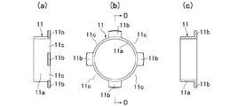
即ち、前記押し輪11は、図1、図2及び図4に示す如く、差し金具本体10の差込み筒部10bの外周面に円周方向へ回転自在且つ軸線方向へスライド自在に嵌合される押込み筒部11aと、押込み筒部11aの基端部に連設された鍔部11bと、鍔部11bに等角度ごとに形成され、押し輪11を回転させたときに保護バンド9のスペーサ部9aに合致してスペーサ部9aが通過可能な三つの切欠き部11cとを備えている。
That is, as shown in FIGS. 1, 2 and 4, the
また、押し輪11の各切欠き部11cは、図4に示す如く、円弧形状に形成されており、各切欠き部11cの幅(切欠き部11cの円周方向長さ)は、保護バンド9のスペーサ部9aの長さよりも大きめに形成されている。
Each
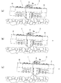
そして、前記押し輪11は、押し輪11の鍔部11bと保護バンド9の各スペーサ部9aとが合致する状態で受け金具1内に押し込まれ、鍔部11bが保護バンド9の各スペーサ部9aに当接して押し輪11の受け金具1側への移動を防止する移動防止位置(図1及び図5(d)参照)と、押し輪11の各切欠き部11cと保護バンド9の各スペーサ部9aとが合致する状態で受け金具1内に押し込まれて受け金具1と差し金具2の結合状態を解除する結合解除位置(図7(c)参照)とを取り得るように構成されている。
Then, the
而して、上述した差込み式の結合金具の受け金具1と差し金具2を結合する場合には、先ず、差し金具本体10の差込み筒部10bを受け金具1の環状の締め輪4及び爪座5内に差し込む。そうすると、差込み筒部10bの先端が爪座5の内方へ突出している爪6に当接するが、爪6の内面が傾斜面6aとなっているために差し金具本体10の押圧力によって爪6が板バネ7の弾性力に抗して外方へ押し広げられる。これにより、差し金具本体10の差込み筒部10bは、爪座5内に順次差し込まれて行く。
Thus, when the
差し金具本体10の差込み筒部10bに形成した環状突部10cが受け金具1の各爪6を越える位置まで差し込まれると、爪6が板バネ7の弾性力により爪座5の内方へ突出し、差込み筒部10bの環状突部10cの背面側へ係止される(図5(a)参照)。これにより受け金具1と差し金具2は、抜け止めされた状態に結合される。
When the
受け金具1と差し金具2が結合されたら、押し輪11の鍔部11bと保護バンド9の各スペーサ部9aとが完全に合致するように、若しくは、押し輪11の鍔部11bの一部分と保護バンド9の各スペーサ部9aの一部分とが合致するように押し輪11を回転操作する(図5(b)及び図5(c)参照)。
When the
その後、押し輪11を受け金具1内に押し込んで行くと、押し輪11の鍔部11bが保護バンド9のスペーサ部9aに当接し、押し輪11が移動防止位置に移動する(図5(d)参照)。このとき、保護バンド9の回転止め摩擦面9bが押し輪11の押込み筒部11aの外周面に面接触状態で当接するため、押し輪11の不用意な回転が阻止され、押し輪11の鍔部11bの切り欠き部11cと保護バンド9のスペーサ部9aとが合致すると言うことがなく、押し輪11は移動防止位置に確実且つ良好に保持されることになる。
Thereafter, when the
このように、受け金具1と差し金具2を結合し、差し金具2の押し輪11を移動防止位置すると、押し輪11が外部との接触により外力を受けても、不用意に受け金具1側へ動くと言うことがない。
その結果、上述した差込み式の結合金具は、消防用ホースHを引きずったときや消防用ホースHの運搬時等に押し輪11が地面等と接触して外力を受けても、押し輪11が受け金具1と差し金具2の結合状態を解除する方向へ動くと言うことがなく、受け金具1と差し金具2の結合が解除されるのを確実に防止することができると共に、押し輪11が地面の突起物を乗り越えることが可能となる(図6参照)。
In this way, when the
As a result, the above-described plug-type coupling metal fittings can be used even when the
一方、差込み式の結合金具の受け金具1と差し金具2の結合を解除する場合には、押し輪11の各切欠き部11cと保護バンド9の各スペーサ部9aとが完全に合致するように移動防止位置にある押し輪11を回転操作し、この状態で押し輪11を受け金具1内に押し込んで結合解除位置にする(図7(a)、図7(b)及び図7(c)参照)。そうすると、押し輪11の押込み筒部11aの先端部が受け金具1の爪6の傾斜面6aを押し、各爪6が板バネ7の弾性力に抗して差し金具2の環状突部10cの外径よりも外方へ押し広げられ、環状突部10cと各爪6の係止が外れる。これによって、受け金具1から差し金具2を引き抜くことができ、受け金具1と挿し金具の結合を解除することができる(図7(d)参照)。
On the other hand, when the coupling between the receiving
図8及び図9は保護バンド9及び押し輪11の他の例を示すものであり、前記保護バンド9は、四つのスペーサ部9aを、また、前記押し輪11は、四つの切欠き部11cをそれぞれ備えている。
8 and 9 show another example of the
即ち、保護バンド9の四つのスペーサ部9aは、図8に示す如く、保護バンド9の一方の側面(押し輪11に対向する側面)に90度間隔で一体的に突出形成されており、側面視(図8(c)参照)において円弧形状を呈している。各スペーサ部9aの内周面は、同一の円周上に配置されており、押し輪11の押込み筒部11aの外周面に面接触状態で当接し、押し輪11の不用意な回転を阻止する回転止め摩擦面9bに形成されている。
That is, as shown in FIG. 8, the four
また、押し輪11の四つの切欠き部11cは、図9に示す如く、押し輪11の鍔部11bに90度間隔で形成されており、押し輪11を回転させたときに保護バンド9の各スペーサ部9aに合致してスペーサ部9aが通過可能となっている。各切欠き部11cの幅(切欠き部11cの円周方向長さ)は、保護バンド9のスペーサ部9aの長さよりも大きめに形成されている。
Further, as shown in FIG. 9, the four
図10及び図11は保護バンド9及び押し輪11の更に他の例を示すものであり、前記保護バンド9は、二つのスペーサ部9aを、また、前記押し輪11は、二つの切欠き部11cをそれぞれ備えている。
10 and 11 show still another example of the
即ち、保護バンド9の二つのスペーサ部9aは、図10に示す如く、保護バンド9の一方の側面(押し輪11に対向する側面)に180度間隔で一体的に突出形成されており、側面視(図10(c)参照)において半円弧形状を呈している。各スペーサ部9aの内周面は、同一の円周上に配置されており、押し輪11の押込み筒部11aの外周面に面接触状態で当接し、押し輪11の不用意な回転を阻止する回転止め摩擦面9bに形成されている。
That is, as shown in FIG. 10, the two
また、押し輪11の二つの切欠き部11cは、図11に示す如く、押し輪11の鍔部11bに180度間隔で形成されており、押し輪11を回転させたときに保護バンド9の各スペーサ部9aに合致してスペーサ部9aが通過可能となっている。各切欠き部11cの幅(切欠き部11cの円周方向長さ)は、保護バンド9のスペーサ部9aの長さよりも大きめに形成されている。
Further, as shown in FIG. 11, the two
図8〜図11に示す保護バンド9及び押し輪11を用いた差込み式の結合金具も、図3及び図4に示す保護バンド9及び押し輪11を用いた差込み式の結合金具と同様の作用効果を奏することができる。
The insertion type fittings using the
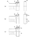
図12及び図13は本発明を既存の差込み式の結合金具に適用したものである。即ち、既存の受け金具20の保護バンド28を締め輪23から取り外し、本発明のスペーサ部9aを備えた保護バンド9に交換し、また、既存の差し金具21の押し輪30を差し金具本体29から取り外し、本発明の切欠き部11cを備えた押し輪11に交換したものである。
12 and 13 show the present invention applied to an existing plug-in type fitting. That is, the
更に、図14は本発明の受け金具1の変形例を示し、本発明の受け金具1に既存の差し金具21と本発明の差し金具2の双方を結合できるようにしたものである。
即ち、図14に示す受け金具1は、切欠き部11cを備えた押し輪11に変更できていない既存の差し金具21を接続する場合に用いるものであり、保護バンド9のスペーサ部9aのサイズ、つまりスペーサ部9aの内周面内径を既存の差し金具21の押し輪30の鍔部外径よりも大きくすることで、本発明の受け金具1に既存の差し金具21が結合可能となる(図14(a)参照)。
また、本発明の差し金具2の押し輪11の鍔部11b外径を前記スペーサ部9aの内周面内径よりも大きくしておくことで、本発明の受け金具1に本発明の差し金具2を結合可能となる(図14(b)参照)。
Further, FIG. 14 shows a modification of the receiving metal fitting 1 of the present invention, in which both the existing
That is, the receiving
Further, by setting the outer diameter of the
このように、本発明を既存の差込み式の結合金具に適用した場合、既存の差込み式の結合金具であっても、消防用ホースHの引きずり時等に受け金具20と差し金具21の結合が解除されるのを防止することができる。
As described above, when the present invention is applied to an existing plug-in type fitting, even if the existing plug-type fitting is used, the fitting of the receiving
尚、上記の実施形態においては、保護バンド9にスペーサ部9aを二つ〜四つ形成すると共に、押し輪11に切欠き部11cを二つ〜四つ形成するようにしたが、他の実施形態においては、保護バンド9にスペーサ部9aを一つ又は五つ以上形成すると共に、押し輪11に切欠き部11cを一つ又は五つ以上形成するようにしても良い。また、スペーサ部9a及び切欠き部11cの形状も図3、図4、図8〜図11に示す形状のものに限定されるものではなく、押し輪11が移動防止位置と結合解除位置とを取ることができれば、如何なる形状であっても良い。
In the above embodiment, the
また、上記の実施形態においては、保護バンド9にスペーサ部9aを一体的に形成したが、他の実施形態においては、スペーサ部9aを保護バンド9と別体に形成し、保護バンド9に後で取り付けるようにしても良い。
In the above embodiment, the
本発明は、差込み式の結合金具を用いて消防用ホースH同士を着脱自在に結合するようにしたが、本発明の差込み式の結合金具を用いて消防用ホースHと消火栓弁、消防用ホースHとノズル、消防用ホースHと消防車自動車の吐出口をそれぞれ着脱自在に結合するようにしても良い。 In the present invention, the fire hoses H are detachably coupled to each other by using the plug-in coupling metal fittings. However, the fire hose H, the fire hydrant valve, and the fire hose are constructed by using the plug-in coupling metal fittings of the present invention. You may make it connect H and a nozzle, the hose H for fire fighting, and the discharge port of a fire engine car so that attachment or detachment is possible respectively.
1は受け金具、2は差し金具、3は受け金具本体、3aはホース結合筒部、3bは受け口部、4は締め輪、5は爪座、6は爪、6aは傾斜面、7は板バネ、8は環状パッキン、9は保護バンド、9aはスペーサ部、9bは回転止め摩擦面、10は差し金具本体、10aはホース結合筒部、10bは差込み筒部、10cは環状突部、11は押し輪、11aは押込み筒部、11bは鍔部、11cは切欠き部、12はかしめ用リング、13はビス、14はピン、15は止め輪、Hは消防用ホース。 1 is a receiving bracket, 2 is a fitting, 3 is a receiving bracket body, 3a is a hose coupling cylinder, 3b is a receiving port, 4 is a fastening ring, 5 is a claw seat, 6 is a claw, 6a is an inclined surface, and 7 is a plate Spring, 8 is an annular packing, 9 is a protective band, 9a is a spacer portion, 9b is a rotation-preventing friction surface, 10 is a metal fitting body, 10a is a hose coupling cylinder portion, 10b is an insertion cylinder portion, 10c is an annular projection portion, 11 Is a push ring, 11a is a pushing cylinder part, 11b is a collar part, 11c is a notch part, 12 is a caulking ring, 13 is a screw, 14 is a pin, 15 is a retaining ring, and H is a fire hose.
Claims (3)
Priority Applications (1)
| Application Number | Priority Date | Filing Date | Title |
|---|---|---|---|
| JP2016107435A JP2017213065A (en) | 2016-05-30 | 2016-05-30 | Plug-in fitting |
Applications Claiming Priority (1)
| Application Number | Priority Date | Filing Date | Title |
|---|---|---|---|
| JP2016107435A JP2017213065A (en) | 2016-05-30 | 2016-05-30 | Plug-in fitting |
Publications (1)
| Publication Number | Publication Date |
|---|---|
| JP2017213065A true JP2017213065A (en) | 2017-12-07 |
Family
ID=60574926
Family Applications (1)
| Application Number | Title | Priority Date | Filing Date |
|---|---|---|---|
| JP2016107435A Pending JP2017213065A (en) | 2016-05-30 | 2016-05-30 | Plug-in fitting |
Country Status (1)
| Country | Link |
|---|---|
| JP (1) | JP2017213065A (en) |
Cited By (4)
| Publication number | Priority date | Publication date | Assignee | Title |
|---|---|---|---|---|
| JP2017219106A (en) * | 2016-06-07 | 2017-12-14 | 株式会社横井製作所 | Insertion type fitting |
| CN110319289A (en) * | 2019-07-31 | 2019-10-11 | 乐清市乐可力气动科技有限公司 | A kind of high pressure resistant quick connector and its press gland |
| JP2021196045A (en) * | 2020-06-18 | 2021-12-27 | 櫻護謨株式会社 | Bonding bracket |
| JP7667564B2 (en) | 2021-09-22 | 2025-04-23 | 株式会社丸共ユニオン | Fire-fighting fittings |
-
2016
- 2016-05-30 JP JP2016107435A patent/JP2017213065A/en active Pending
Cited By (6)
| Publication number | Priority date | Publication date | Assignee | Title |
|---|---|---|---|---|
| JP2017219106A (en) * | 2016-06-07 | 2017-12-14 | 株式会社横井製作所 | Insertion type fitting |
| CN110319289A (en) * | 2019-07-31 | 2019-10-11 | 乐清市乐可力气动科技有限公司 | A kind of high pressure resistant quick connector and its press gland |
| CN110319289B (en) * | 2019-07-31 | 2023-09-22 | 乐清市乐可力气动科技有限公司 | High-pressure-resistant quick connector and pressing cover thereof |
| JP2021196045A (en) * | 2020-06-18 | 2021-12-27 | 櫻護謨株式会社 | Bonding bracket |
| JP7434076B2 (en) | 2020-06-18 | 2024-02-20 | 櫻護謨株式会社 | joining metal fittings |
| JP7667564B2 (en) | 2021-09-22 | 2025-04-23 | 株式会社丸共ユニオン | Fire-fighting fittings |
Similar Documents
| Publication | Publication Date | Title |
|---|---|---|
| JP5864164B2 (en) | Fire hose coupling fittings | |
| JP5534954B2 (en) | Fire hose fittings | |
| JPS5847184B2 (en) | Attachment for breathing apparatus | |
| TW200944683A (en) | A female coupling element and a quick coupling including such an element | |
| JP2017214949A (en) | Plug-in type coupled fitting | |
| CN103562609A (en) | Compressed air coupling | |
| JP6718168B2 (en) | Plug-in type fitting | |
| JP5977403B2 (en) | Fire hose coupling fittings | |
| JP7019762B2 (en) | Bonding bracket | |
| JP7198044B2 (en) | hose fittings | |
| JP7667564B2 (en) | Fire-fighting fittings | |
| JP3742003B2 (en) | Fire hose coupling fittings | |
| JP6581051B2 (en) | Plug-in coupling | |
| JP7539799B2 (en) | Connecting hardware | |
| JP2022020180A (en) | Metal fitting | |
| JP3216797U (en) | Coupling metal fittings, insert metal fittings and sliding cylinders used therefor | |
| JP5393513B2 (en) | Hose fittings | |
| JP2022014104A (en) | Joint fitting | |
| JP3216796U (en) | Coupling metal fittings, insert metal fittings and sliding cylinders used therefor | |
| JP2022061234A (en) | Insert bracket of plug-in type fitting and push-ring guard ring for insert bracket | |
| JPH11201357A (en) | Coupling structure of fire-fighting hose | |
| JP3038232U (en) | Fire fitting fittings | |
| JP2022118437A (en) | Push ring lock tool, protection rubber band and insertion-type coupling metal fitting | |
| JP2022021707A (en) | Metal fitting | |
| JPH0722756U (en) | Tube connection device |