JP2017223301A - Planetary roller screw type linear motion mechanism and electric brake device - Google Patents
Planetary roller screw type linear motion mechanism and electric brake device Download PDFInfo
- Publication number
- JP2017223301A JP2017223301A JP2016119661A JP2016119661A JP2017223301A JP 2017223301 A JP2017223301 A JP 2017223301A JP 2016119661 A JP2016119661 A JP 2016119661A JP 2016119661 A JP2016119661 A JP 2016119661A JP 2017223301 A JP2017223301 A JP 2017223301A
- Authority
- JP
- Japan
- Prior art keywords
- carrier
- planetary roller
- rotating shaft
- axial direction
- linear motion
- Prior art date
- Legal status (The legal status is an assumption and is not a legal conclusion. Google has not performed a legal analysis and makes no representation as to the accuracy of the status listed.)
- Granted
Links
Images


Landscapes
- Transmission Devices (AREA)
- Braking Systems And Boosters (AREA)
- Braking Arrangements (AREA)
Abstract
【課題】外輪部材から対象物に負荷する軸方向荷重に応じて荷重変換率を切り替えることが可能であり、しかも、回転軸の外周の遊星ローラが転がり接触する円筒面を研磨等によって容易に仕上げることが可能な遊星ローラねじ式直動機構を提供する。【解決手段】外輪部材5の内周の螺旋凸条16と遊星ローラ13の外周の円周溝17との係合によって外輪部材5が軸方向に移動する遊星ローラねじ式直動機構において、軸方向後方への反力によってキャリア14が回転軸8に対して相対移動するように弾性部材35で支持され、キャリア14が回転軸8に対して相対移動していない状態ではキャリア14と摩擦結合し、キャリア14が回転軸8に対して相対移動した状態ではキャリア14との摩擦結合を解除するテーパ面38が回転軸8の外周に設けられ、テーパ面38は、遊星ローラ13に対して軸方向後方に配置されている。【選択図】図2PROBLEM TO BE SOLVED: To switch a load conversion rate according to an axial load applied to an object from an outer ring member, and to easily finish a cylindrical surface on which a planetary roller on the outer circumference of a rotating shaft rolls and contacts by polishing or the like. It provides a planetary roller screw type linear motion mechanism capable of. SOLUTION: In a planetary roller screw type linear motion mechanism in which an outer ring member 5 moves in an axial direction by engaging a spiral ridge 16 on the inner circumference of an outer ring member 5 with a circumferential groove 17 on the outer circumference of a planetary roller 13, a shaft. The carrier 14 is supported by the elastic member 35 so as to move relative to the rotating shaft 8 due to the reaction force in the rearward direction, and when the carrier 14 does not move relative to the rotating shaft 8, it is frictionally coupled with the carrier 14. When the carrier 14 is relatively moved with respect to the rotating shaft 8, a tapered surface 38 for releasing frictional coupling with the carrier 14 is provided on the outer periphery of the rotating shaft 8, and the tapered surface 38 is axially oriented with respect to the planetary roller 13. It is located behind. [Selection diagram] Fig. 2
Description
この発明は、電動式直動アクチュエータに用いられる遊星ローラねじ式直動機構、およびその遊星ローラねじ式直動機構を用いた電動ブレーキ装置に関する。 The present invention relates to a planetary roller screw type linear motion mechanism used for an electric linear motion actuator and an electric brake device using the planetary roller screw type linear motion mechanism.
外部から入力される回転運動を直線運動に変換して出力する直動機構として、例えば、特許文献1のような遊星ローラねじ式直動機構が知られている。 As a linear motion mechanism that converts an externally input rotational motion into a linear motion and outputs the linear motion, for example, a planetary roller screw type linear motion mechanism as in Patent Document 1 is known.
特許文献1の遊星ローラねじ式直動機構は、外部から回転が入力される回転軸と、その回転軸の外周の円筒面に転がり接触する複数の遊星ローラと、その複数の遊星ローラを自転可能かつ公転可能に保持するキャリアと、複数の遊星ローラを囲むように配置された外輪部材とを有する。外輪部材の内周には螺旋凸条が設けられ、その螺旋凸条と係合する螺旋溝または円周溝が各遊星ローラの外周に設けられている。 The planetary roller screw type linear motion mechanism of Patent Document 1 is capable of rotating a rotating shaft to which rotation is input from the outside, a plurality of planetary rollers that are in rolling contact with an outer peripheral cylindrical surface of the rotating shaft, and the plurality of planetary rollers. And a carrier that is revolved and an outer ring member that is disposed so as to surround the plurality of planetary rollers. A spiral ridge is provided on the inner periphery of the outer ring member, and a spiral groove or a circumferential groove that engages with the spiral ridge is provided on the outer periphery of each planetary roller.
この遊星ローラねじ式直動機構は、外部から回転軸に回転が入力されると、その回転軸の回転が、回転軸の外周に転がり接触する遊星ローラに伝達し、各遊星ローラが自転しながら回転軸のまわりを公転する。このとき、遊星ローラの外周の螺旋溝または円周溝と外輪部材の内周の螺旋凸条との係合によって外輪部材が軸方向に移動する。このようにして、遊星ローラねじ式直動機構は、回転軸の回転を外輪部材の直線運動に変換する。 In this planetary roller screw type linear motion mechanism, when rotation is input from the outside to the rotating shaft, the rotation of the rotating shaft is transmitted to the planetary roller that is in rolling contact with the outer periphery of the rotating shaft, and each planetary roller rotates. Revolve around the axis of rotation. At this time, the outer ring member moves in the axial direction by the engagement of the spiral groove or circumferential groove on the outer periphery of the planetary roller and the spiral protrusion on the inner periphery of the outer ring member. In this way, the planetary roller screw type linear motion mechanism converts the rotation of the rotation shaft into a linear motion of the outer ring member.
この遊星ローラねじ式直動機構は、電動ブレーキ装置に使用することができる。この場合、ブレーキをかけるときは、電動モータの回転が遊星ローラねじ式直動機構によってブレーキパッドの直線運動に変換され、そのブレーキパッドがブレーキディスクに押さえ付けられる。一方、ブレーキを解除するときは、電動モータを逆方向に回転させ、ブレーキパッドとブレーキディスクの間にクリアランスが設けられる。 This planetary roller screw type linear motion mechanism can be used for an electric brake device. In this case, when the brake is applied, the rotation of the electric motor is converted into a linear motion of the brake pad by the planetary roller screw type linear motion mechanism, and the brake pad is pressed against the brake disc. On the other hand, when releasing the brake, the electric motor is rotated in the reverse direction, and a clearance is provided between the brake pad and the brake disk.
ここで、外輪部材の内周の螺旋凸条のリード角を大きく設定すると、外輪部材の軸方向の移動速度が早くなるので、ブレーキをかけるときに、ブレーキパッドがブレーキディスクに接触するまでに要する時間が短くなり、ブレーキの応答性を高めることができるが、その反面、荷重変換率が小さくなるので、ブレーキパッドがブレーキディスクを押圧する力が小さくなるという問題がある。一方、外輪部材の内周の螺旋凸条のリード角を小さく設定すると、荷重変換率が大きくなるので、ブレーキをかけるときに、ブレーキパッドがブレーキディスクを押圧する力を大きくすることが可能となるが、その反面、外輪部材の軸方向の移動速度が遅くなるので、ブレーキパッドがブレーキディスクに接触するまでに要する時間が長くなり、ブレーキの応答性が低下してしまう。つまり、ブレーキの応答性を高めることと、ブレーキパッドがブレーキディスクを押圧する力を大きくすることとは、相反関係にある。 Here, if the lead angle of the spiral protrusion on the inner periphery of the outer ring member is set to be large, the moving speed in the axial direction of the outer ring member is increased, so that it is necessary for the brake pad to come into contact with the brake disc when the brake is applied. Although the time is shortened and the responsiveness of the brake can be improved, the load conversion rate is reduced, but there is a problem that the force with which the brake pad presses the brake disc is reduced. On the other hand, if the lead angle of the spiral protrusion on the inner periphery of the outer ring member is set to be small, the load conversion rate increases, so that it is possible to increase the force with which the brake pad presses the brake disc when braking. However, since the moving speed of the outer ring member in the axial direction is slow, the time required for the brake pad to come into contact with the brake disk becomes long, and the response of the brake is lowered. That is, there is a conflict between increasing the response of the brake and increasing the force with which the brake pad presses the brake disc.
そこで、特許文献1は、ブレーキの応答性を高めることと、ブレーキパッドがブレーキディスクを押圧する力を大きくすることとを両立させるため、外輪部材から対象物に負荷する軸方向荷重に応じて荷重変換率が切り替わる構造を提案している。 Therefore, in Patent Document 1, in order to improve both the response of the brake and increase the force with which the brake pad presses the brake disc, a load is applied according to the axial load applied to the object from the outer ring member. It proposes a structure that changes conversion rate.
すなわち、外輪部材が対象物に軸方向前方への荷重を負荷したときに受ける軸方向後方への反力により、キャリアが回転軸に対して軸方向後方に相対移動するようにキャリアを弾性部材で支持している。また、キャリアが回転軸に対して軸方向後方に相対移動していない状態では、キャリアと回転軸の相対回転を制限するようにキャリアと摩擦結合し、キャリアが回転軸に対して軸方向後方に相対移動した状態では、キャリアと回転軸の相対回転を許容するようにキャリアとの摩擦結合を解除する摩擦結合部を回転軸の外周に設けている。ここで、摩擦結合部は、遊星ローラが転がり接触する円筒面から軸方向前方に向かって次第に大径となるように回転軸の軸方向前端部の外周に設けられたテーパ面である。 That is, the carrier is made of an elastic member so that the carrier moves relative to the rotation axis in the axial rearward direction by the reaction force in the axial rearward direction that is received when the outer ring member applies a load in the axial direction forward to the object. I support it. In addition, when the carrier is not moved relative to the rotation axis in the axial direction rearward, the carrier is frictionally coupled with the carrier so as to limit the relative rotation between the carrier and the rotation axis, and the carrier is moved rearward in the axial direction with respect to the rotation axis. In the state of relative movement, a friction coupling portion for releasing the frictional coupling with the carrier is provided on the outer periphery of the rotation shaft so as to allow relative rotation between the carrier and the rotation shaft. Here, the friction coupling portion is a tapered surface provided on the outer periphery of the front end portion in the axial direction of the rotating shaft so that the diameter gradually increases from the cylindrical surface with which the planetary roller is in rolling contact toward the front in the axial direction.
本願の発明者は、上記の遊星ローラねじ式直動機構において、回転軸の外周の遊星ローラが転がり接触する円筒面を研磨等によって高精度に仕上げるときに、回転軸の形状が、仕上げ加工の難しい形状となっている点に気付いた。 In the above planetary roller screw type linear motion mechanism, the inventor of the present application, when finishing the cylindrical surface with which the planetary roller on the outer periphery of the rotating shaft is in rolling contact with high precision by polishing or the like, the shape of the rotating shaft is the finish processing. I noticed a difficult shape.
すなわち、特許文献1の遊星ローラねじ式直動機構においては、遊星ローラが転がり接触する円筒面から軸方向前方に向かって次第に大径となるテーパ面が設けられている。そして、このテーパ面は、遊星ローラが転がり接触する円筒面よりも大きい外径をもつ部位である。そのため、回転軸の外周を転がり支持しながら回転軸の外周を加工する低コストの加工方法(例えば、センタレス通し研磨)を採用することができず、遊星ローラが転がり接触する円筒面を高精度に仕上げるための加工コストが高くなるという問題がある。 That is, in the planetary roller screw type linear motion mechanism of Patent Document 1, a tapered surface having a diameter gradually increasing from the cylindrical surface to which the planetary roller is in rolling contact toward the front in the axial direction is provided. And this taper surface is a site | part which has an outer diameter larger than the cylindrical surface which a planetary roller rolls and contacts. Therefore, it is not possible to adopt a low-cost processing method (for example, centerless through polishing) that processes the outer periphery of the rotating shaft while rolling and supporting the outer periphery of the rotating shaft, and the cylindrical surface on which the planetary roller is in contact with the rolling is highly accurate. There exists a problem that the processing cost for finishing becomes high.
この発明が解決しようとする課題は、外輪部材から対象物に負荷する軸方向荷重に応じて荷重変換率を切り替えることが可能であり、しかも、回転軸の外周の遊星ローラが転がり接触する円筒面を研磨等によって容易に仕上げることが可能な遊星ローラねじ式直動機構を提供することである。 The problem to be solved by the present invention is that the load conversion rate can be switched according to the axial load applied to the object from the outer ring member, and the planetary roller on the outer periphery of the rotating shaft is in rolling contact with the cylindrical surface It is to provide a planetary roller screw type linear motion mechanism that can be easily finished by polishing or the like.
上記課題を解決するため、この発明では、以下の構成の遊星ローラねじ式直動機構を提供する。
外周に円筒面をもつ回転軸と、
前記円筒面に転がり接触する複数の遊星ローラと、
その複数の遊星ローラを自転可能かつ公転可能に保持するキャリアと、
前記複数の遊星ローラを囲むように配置され、軸方向に移動可能に支持された外輪部材と、
その外輪部材の内周に設けられた螺旋凸条と、
その螺旋凸条と係合するように前記各遊星ローラの外周に設けられた螺旋溝または円周溝とを有し、
前記螺旋凸条と前記螺旋溝または円周溝との係合によって前記外輪部材が軸方向に移動する遊星ローラねじ式直動機構において、
前記外輪部材に対して対象物に軸方向一方への荷重を負荷したときに受ける軸方向他方への反力により、前記キャリアが前記回転軸に対して軸方向他方に相対移動するように前記キャリアを支持する弾性部材と、
前記回転軸の外周に設けられ、前記キャリアが前記回転軸に対して軸方向他方に相対移動していない場合には、前記キャリアと前記回転軸の相対回転を制限するように前記キャリアと摩擦結合し、前記キャリアが前記回転軸に対して軸方向他方に相対移動した場合には、前記キャリアと前記回転軸の相対回転を許容するように前記キャリアとの摩擦結合を解除する、摩擦結合部とを備え、
前記摩擦結合部は、前記遊星ローラに対して軸方向他方に配置されていることを特徴とする遊星ローラねじ式直動機構。
In order to solve the above problems, the present invention provides a planetary roller screw type linear motion mechanism having the following configuration.
A rotating shaft having a cylindrical surface on the outer periphery;
A plurality of planetary rollers in rolling contact with the cylindrical surface;
A carrier that holds the plurality of planetary rollers in a rotatable and revolving manner;
An outer ring member disposed so as to surround the plurality of planetary rollers and supported so as to be movable in the axial direction;
A spiral ridge provided on the inner periphery of the outer ring member;
A spiral groove or a circumferential groove provided on the outer periphery of each planetary roller so as to engage with the spiral protrusion,
In the planetary roller screw type linear motion mechanism in which the outer ring member moves in the axial direction by the engagement of the spiral ridge and the spiral groove or the circumferential groove,
The carrier moves so that the carrier moves relative to the rotational axis in the other axial direction by a reaction force in the other axial direction received when a load is applied to the outer ring member in one axial direction. An elastic member that supports
Provided on the outer periphery of the rotating shaft, and when the carrier does not move relative to the rotating shaft in the other axial direction, the carrier and the friction coupling so as to limit the relative rotation of the carrier and the rotating shaft A friction coupling portion that releases the frictional coupling between the carrier and the carrier so as to allow relative rotation between the carrier and the rotation shaft when the carrier moves relative to the rotation axis in the other axial direction; With
The planetary roller screw type linear motion mechanism, wherein the frictional coupling portion is disposed on the other side in the axial direction with respect to the planetary roller.
このようにすると、外輪部材から対象物に荷重を負荷していない状態では、回転軸の外周の摩擦結合部がキャリアと摩擦結合し、キャリアと回転軸の相対回転が制限される。そのため、外部から回転軸に回転が入力されたときに、回転軸と一体にキャリアが公転し、遊星ローラは自転せずに回転軸のまわりを公転する。このとき、遊星ローラの公転速度は比較的速いものとなる。そのため、外輪部材の軸方向の移動速度が早くなり、荷重変換率が小さくなる。一方、外輪部材から対象物に荷重を負荷した状態では、回転軸の外周の摩擦結合部とキャリアとの摩擦結合が解除され、キャリアと回転軸の相対回転が許容される。そのため、外部から回転軸に回転が入力されたときに、遊星ローラが自転しながら回転軸のまわりを公転する。このとき、遊星ローラの公転速度は比較的遅いものとなる。そのため、外輪部材の軸方向の移動速度が遅くなり、荷重変換率が大きくなる。このように、荷重変換率を、外輪部材から対象物に負荷する軸方向荷重に応じて切り替えることが可能となっている。 In this way, in a state where no load is applied to the object from the outer ring member, the friction coupling portion on the outer periphery of the rotation shaft is frictionally coupled with the carrier, and the relative rotation between the carrier and the rotation shaft is limited. Therefore, when rotation is input from the outside to the rotating shaft, the carrier revolves integrally with the rotating shaft, and the planetary roller revolves around the rotating shaft without rotating. At this time, the revolution speed of the planetary roller is relatively fast. Therefore, the moving speed of the outer ring member in the axial direction is increased, and the load conversion rate is reduced. On the other hand, in a state where a load is applied from the outer ring member to the object, the frictional coupling between the frictional coupling portion on the outer periphery of the rotating shaft and the carrier is released, and relative rotation between the carrier and the rotating shaft is allowed. Therefore, when rotation is input from the outside to the rotating shaft, the planetary roller revolves around the rotating shaft while rotating. At this time, the revolution speed of the planetary roller is relatively slow. Therefore, the moving speed of the outer ring member in the axial direction becomes slow, and the load conversion rate increases. Thus, the load conversion rate can be switched according to the axial load applied to the object from the outer ring member.
また、回転軸の外周の摩擦結合部は、通常、軸方向一方(軸方向前方)から軸方向他方(軸方向後方)に向かって小径となる部位をもつ形状であり、この摩擦結合部が、遊星ローラに対して軸方向他方(外輪部材から対象物に荷重を負荷する方向に対して逆向きの軸方向、すなわち軸方向後方)に配置されていることから、遊星ローラが転がり接触する円筒面を、回転軸の最大径部分とすることが可能である。そのため、回転軸の外周を転がり支持しながら回転軸の外周を加工する低コストの加工方法(例えば、センタレス通し研磨)を採用することが可能であり、遊星ローラが転がり接触する円筒面を研磨等によって容易に仕上げることが可能である。 In addition, the friction coupling portion on the outer periphery of the rotating shaft is usually in a shape having a portion having a small diameter from one axial direction (front in the axial direction) to the other axial direction (back in the axial direction). A cylindrical surface on which the planetary roller is in rolling contact with the planetary roller because it is disposed in the other axial direction (axial direction opposite to the direction in which the load is applied to the object from the outer ring member, that is, axially rearward). Can be the maximum diameter portion of the rotating shaft. Therefore, it is possible to employ a low-cost processing method (for example, centerless through polishing) that processes the outer periphery of the rotating shaft while rolling and supporting the outer periphery of the rotating shaft, and polishing the cylindrical surface on which the planetary roller is in rolling contact. It is possible to finish easily.
前記摩擦係合部としては、軸方向一方から他方に向かって外径が小さくなるテーパ面を採用することができる。 As the friction engagement portion, a tapered surface whose outer diameter decreases from one axial direction to the other can be employed.
このようにすると、キャリアと、回転軸の外周の摩擦結合部とが摩擦結合したときに、テーパ面のくさび作用によって大きな摩擦力を発生することが可能である。 In this way, when the carrier and the frictional coupling portion on the outer periphery of the rotating shaft are frictionally coupled, a large frictional force can be generated by the wedge action of the tapered surface.
また、この発明では、上記の遊星ローラねじ式直動機構を用いた電動ブレーキ装置として、以下の構成のものを併せて提供する。
上記構成の遊星ローラねじ式直動機構と、
前記遊星ローラねじ式直動機構の回転軸を回転駆動する電動モータと、
前記遊星ローラねじ式直動機構の外輪部材と一体に移動するブレーキパッドと、
前記ブレーキパッドに対向して配置されたブレーキディスクと、
を有する電動ブレーキ装置。
Moreover, in this invention, the thing of the following structures is also provided together as an electric brake device using said planetary roller screw type linear motion mechanism.
A planetary roller screw type linear motion mechanism configured as described above;
An electric motor that rotationally drives the rotating shaft of the planetary roller screw type linear motion mechanism;
A brake pad that moves integrally with the outer ring member of the planetary roller screw type linear motion mechanism;
A brake disc disposed opposite the brake pad;
Electric brake device having
この発明の遊星ローラねじ式直動機構は、外輪部材から対象物に負荷する軸方向荷重に応じて荷重変換率を切り替えることが可能である。また、回転軸の外周の摩擦結合部が、遊星ローラに対して軸方向他方に配置されていることから、遊星ローラが転がり接触する円筒面を、回転軸の最大径部分とすることが可能である。そのため、回転軸の外周を転がり支持しながら回転軸の外周を加工する低コストの加工方法(例えば、センタレス通し研磨)を採用することが可能であり、遊星ローラが転がり接触する円筒面を研磨等によって容易に仕上げることが可能である。 The planetary roller screw type linear motion mechanism of the present invention can switch the load conversion rate according to the axial load applied to the object from the outer ring member. Further, since the friction coupling portion on the outer periphery of the rotating shaft is disposed on the other side in the axial direction with respect to the planetary roller, the cylindrical surface on which the planetary roller is in rolling contact can be the maximum diameter portion of the rotating shaft. is there. Therefore, it is possible to employ a low-cost processing method (for example, centerless through polishing) that processes the outer periphery of the rotating shaft while rolling and supporting the outer periphery of the rotating shaft, and polishing the cylindrical surface on which the planetary roller is in rolling contact. It is possible to finish easily.
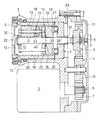
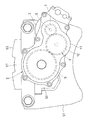
図1に、この発明の実施形態の遊星ローラねじ式直動機構1を用いた電動式直動アクチュエータ2を示す。この電動式直動アクチュエータ2は、電動モータ3と、電動モータ3の回転を減速して伝達する減速歯車列4と、減速歯車列4を介して電動モータ3から入力される回転を外輪部材5の直線運動に変換して出力する遊星ローラねじ式直動機構1とを有する。
FIG. 1 shows an electric
減速歯車列4は、電動モータ3のモータ軸6に固定された入力歯車7と、遊星ローラねじ式直動機構1の回転軸8に固定された出力歯車9と、入力歯車7と出力歯車9の間で回転を伝達する中間歯車10と、これらの歯車7,9,10を収容するギヤケース11とを有する。この減速歯車列4は、電動モータ3のモータ軸6から入力歯車7に入力された回転を、互いに歯数の異なる入力歯車7、中間歯車10、出力歯車9を順に伝達することで減速し、その減速された回転を出力歯車9から回転軸8に出力する。
The
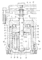
図2、図3に示すように、遊星ローラねじ式直動機構1は、外周に円筒面12をもつ回転軸8と、円筒面12に転がり接触する複数の遊星ローラ13と、その複数の遊星ローラ13を自転可能かつ公転可能に保持するキャリア14と、複数の遊星ローラ13を囲むように配置された中空筒状の外輪部材5と、外輪部材5を軸方向に移動可能に収容するハウジング15とを有する。複数の遊星ローラ13は、外輪部材5の内周と回転軸8の外周との間に周方向に間隔をおいて配置されている。
As shown in FIGS. 2 and 3, the planetary roller screw type linear motion mechanism 1 includes a
ここで、回転軸8と平行な方向を軸方向、外輪部材5のハウジング15からの突出長さが大きくなる側に外輪部材5が移動するときの外輪部材5の移動方向を軸方向前方(一方)、外輪部材5のハウジング15からの突出長さが小さくなる側に外輪部材5が移動するときの外輪部材5の移動方向を軸方向後方(他方)、回転軸8まわりに周回する方向を周方向と定義する。
Here, the direction parallel to the
図2に示すように、外輪部材5の内周には、螺旋凸条16が設けられている。螺旋凸条16は、周方向に対して所定のリード角をもって斜めに延びる凸条である。各遊星ローラ13の外周には、螺旋凸条16に係合する複数の円周溝17が軸方向に間隔をおいて形成されている。各遊星ローラ13の外周の軸方向に隣り合う円周溝17の間隔は、螺旋凸条16のピッチと同一の大きさとされている。ここでは、遊星ローラ13の外周にリード角が0度の円周溝17を設けているが、円周溝17のかわりに、螺旋凸条16と異なるリード角をもつ螺旋溝を設けてもよい。
As shown in FIG. 2,
図2、図3に示すように、キャリア14は、各遊星ローラ13をそれぞれ自転可能に支持する複数の支持ピン18と、各支持ピン18の軸方向前端部を保持する軸方向前側ディスク19と、各支持ピン18の軸方向後端部を保持する軸方向後側ディスク20と、周方向に隣り合う複数の遊星ローラ13の間を通って軸方向前側ディスク19と軸方向後側ディスク20を連結する柱部21とを有する。柱部21は、軸方向前側ディスク19と軸方向後側ディスク20が軸方向と周方向のいずれの方向にも相対移動しないように両ディスク19,20を一体化している。
As shown in FIGS. 2 and 3, the
図2に示すように、軸方向前側ディスク19および軸方向後側ディスク20は、それぞれ回転軸8を貫通させる環状に形成されている。軸方向前側ディスク19の内周には、回転軸8の外周に摺接する滑り軸受22が装着されている。
As shown in FIG. 2, the axial
各遊星ローラ13の内周と支持ピン18の外周との間には、遊星ローラ13を自転可能に支持するラジアル軸受23が組み込まれている。各遊星ローラ13と軸方向後側ディスク20との間には、遊星ローラ13を自転可能な状態で軸方向に支持するスラスト軸受24が組み込まれている。また、スラスト軸受24と軸方向後側ディスク20の間には、スラスト軸受24を介して遊星ローラ13を傾動可能に支持する調心座25が組み込まれている。
Between the inner periphery of each
外輪部材5は、ハウジング15に形成された収容孔26の内面で軸方向にスライド可能に支持されている。ハウジング15の内部には、外輪部材5から軸方向後方に離れた位置に軸受支持部材27が固定されている。軸受支持部材27は、回転軸8を貫通させる円環状に形成されている。軸受支持部材27の内周には、回転軸8を回転可能に支持するラジアル軸受28が組み込まれている。ラジアル軸受28は、例えば、焼結すべり軸受や深溝玉軸受を採用することができる。
The
軸受支持部材27は、収容孔26の内周に設けられた突起部29で軸方向後方への移動が規制され、収容孔26の内周に装着した止め輪30で軸方向前方への移動が規制されている。また、回転軸8は、回転軸8の外周に装着した止め輪31によって軸受支持部材27に対する軸方向前方への相対移動が規制されている。また、キャリア14は、回転軸8の軸方向前端部の外周に装着された止め輪32によって、回転軸8に対する軸方向前方への相対移動が規制されている。
The
ここで、ラジアル軸受28は、軸受支持部材27に対する軸方向前方への相対移動が規制された状態に組み込まれ、止め輪31は、ラジアル軸受28に対して軸方向後側に装着されている。また、止め輪32は、滑り軸受22に対して軸方向前側に装着されている。
Here, the
キャリア14と軸受支持部材27の間には、キャリア14を公転可能な状態で軸方向後側から支持するスラスト軸受33が組み込まれている。また、キャリア14とスラスト軸受33の間には、キャリア14からスラスト軸受33に軸方向荷重を伝達する間座34が組み込まれている。キャリア14と間座34の間には弾性部材35が組み込まれ、さらに間座34とキャリア14の間には、キャリア14の軸方向移動を許容する軸方向隙間36が設けられている。これにより、キャリア14に軸方向後方への荷重が負荷されたときに、その荷重により弾性部材35が軸方向に圧縮し、キャリア14と間座34の間の軸方向隙間36の範囲で、キャリア14が回転軸8に対して軸方向後方に相対移動するようになっている。ここで、キャリア14と間座34の間の軸方向隙間36の大きさは微小である。そのため、キャリア14が回転軸8に対して軸方向後方に相対移動することが可能な距離はきわめて短いもの(例えば、0.5mm以下)となっている。
A
弾性部材35は、回転軸8を貫通させる環状に形成されている。弾性部材35は、例えば皿ばねである。皿ばねにかえて、ウェーブスプリングやコイルばねを採用することも可能である。弾性部材35は、キャリア14に軸方向後方への荷重が全く負荷されていない状態で予め軸方向に圧縮され、キャリア14を付勢している。弾性部材35は、キャリア14に軸方向後方への荷重が負荷されたときにその荷重の大きさに応じて弾性部材35の軸方向の圧縮量が増加する組み込みとされている。
The
間座34のキャリア14との対向面には収容凹部37が形成されている。弾性部材35の一部は収容凹部37に収容され、弾性部材35の残りの部分は、収容凹部37からはみ出している。
An
この実施形態では、キャリア14と間座34の間に弾性部材35を組み込んだが、弾性部材35を組み込む位置は、キャリア14と軸受支持部材27の間であれば他の位置でもよく、例えば、間座34とスラスト軸受33の間に弾性部材35を組み込んでもよく、間座34を軸方向に相対移動可能な2つの分割体で構成し、その2つの分割体の間に弾性部材35を組み込んでもよく、またスラスト軸受33と軸受支持部材27の間に弾性部材35を組み込むようにしてもよい。
In this embodiment, the
回転軸8の外周には、遊星ローラ13が転がり接触する円筒面12と、その円筒面12に対して軸方向後方に位置するテーパ面38(摩擦結合部)と、テーパ面38の軸方向後方に連続する円筒面39とが設けられている。円筒面39は、ラジアル軸受28で支持される面であり、円筒面39の外径は、円筒面12の外径よりも小さい。
On the outer periphery of the
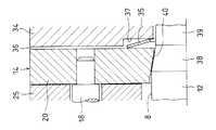
図4に示すように、テーパ面38は、軸方向前側から後側に向かって外径が小さくなる円錐状の面である。テーパ面38の傾斜角(テーパ面38が軸方向と平行な方向に対してなす角度)は、5〜20°の範囲で設定されている。
As shown in FIG. 4, the tapered
キャリア14の軸方向後側ディスク20の内周には、回転軸8の外周のテーパ面38に対向するテーパ内周面40が形成されている。テーパ内周面40の傾斜角(テーパ内周面40が軸方向と平行な方向に対してなす角度)は、5〜20°の範囲で設定されている。テーパ内周面40は、テーパ面38と等しい傾斜角をもつように形成すると好ましい。
A tapered inner
ここで、図4に示すように、キャリア14が回転軸8に対して軸方向後方に相対移動していない状態(すなわち、キャリア14に軸方向後方への荷重が負荷されていない状態)では、キャリア14のテーパ内周面40は、回転軸8の外周のテーパ面38に接触している。このとき、テーパ内周面40とテーパ面38は弾性部材35の力によって摩擦結合し、キャリア14と回転軸8の相対回転がテーパ内周面40とテーパ面38の間の摩擦力によって制限された状態となる。
Here, as shown in FIG. 4, in a state where the
一方、図5に示すように、キャリア14が回転軸8に対して軸方向後方に相対移動した状態(すなわち、キャリア14に軸方向後方への荷重が負荷され、その荷重によって弾性部材35の圧縮量が増加した状態)では、キャリア14のテーパ内周面40が、回転軸8の外周のテーパ面38から離反する。このとき、テーパ内周面40とテーパ面38の摩擦結合が解除され、キャリア14と回転軸8の相対回転が許容された状態となる。
On the other hand, as shown in FIG. 5, the
上記の電動式直動アクチュエータ2の動作例を説明する。
An operation example of the electric
図1に示す電動モータ3のモータ軸6が回転すると、その回転が減速歯車列4によって減速して伝達され、遊星ローラねじ式直動機構1の回転軸8に入力される。
When the
ここで、外輪部材5から対象物に軸方向前方への荷重を負荷していない状態では、キャリア14に軸方向後方への荷重が負荷されないため、図4に示すように、キャリア14のテーパ内周面40と回転軸8の外周のテーパ面38とが摩擦結合し、キャリア14と回転軸8の相対回転が制限される。そのため、図1に示す電動モータ3から減速歯車列4を介して回転軸8に回転が入力されたときに、回転軸8と一体にキャリア14が公転し、遊星ローラ13は自転せずに回転軸8のまわりを公転する。そして、遊星ローラ13の外周の円周溝17と外輪部材5の内周の螺旋凸条16との係合によって、遊星ローラ13と外輪部材5が軸方向に相対移動するが、遊星ローラ13はキャリア14と共に軸方向の移動が規制されているので、遊星ローラ13はハウジング15に対して軸方向に移動せず、外輪部材5がハウジング15に対して軸方向に移動する。
Here, in the state in which no load forward in the axial direction is applied from the
このとき、回転軸8と一体にキャリア14が公転し、遊星ローラ13は自転せずに回転軸8のまわりを公転するため、遊星ローラ13が自転しながら回転軸8のまわりを公転する場合よりも、遊星ローラ13の公転速度は比較的速いものとなる。そのため、外輪部材5の軸方向の移動速度が早くなり、荷重変換率が小さくなる。
At this time, since the
一方、外輪部材5から対象物に軸方向前方への荷重を負荷している状態では、外輪部材5が受ける軸方向後方への反力が遊星ローラ13とスラスト軸受24とを順に介してキャリア14に伝達し、その軸方向後方への反力によって、キャリア14が回転軸8に対して軸方向後方に相対移動し、図5に示すように、キャリア14のテーパ内周面40と回転軸8の外周のテーパ面38の摩擦結合が解除され、キャリア14と回転軸8の相対回転が許容される。そのため、図1に示す電動モータ3から減速歯車列4を介して回転軸8に回転が入力されたときに、遊星ローラ13が支持ピン18を中心に自転しながら回転軸8のまわりを公転する。そして、遊星ローラ13の外周の円周溝17と外輪部材5の内周の螺旋凸条16との係合によって、遊星ローラ13と外輪部材5が軸方向に相対移動するが、遊星ローラ13はキャリア14と共に軸方向の移動が規制されているので、遊星ローラ13はハウジング15に対して軸方向に移動せず、外輪部材5がハウジング15に対して軸方向に移動する。
On the other hand, in a state in which a load in the axial direction forward is applied to the object from the
このとき、遊星ローラ13が自転しながら回転軸8のまわりを公転するため、遊星ローラ13が自転せずに回転軸8のまわりを公転する場合よりも、遊星ローラ13の公転速度は比較的遅いものとなる。そのため、外輪部材5の軸方向の移動速度が遅くなり、荷重変換率が大きくなる。
At this time, since the
以上のように、この電動式直動アクチュエータ2は、外輪部材5から対象物に負荷する軸方向荷重に応じて荷重変換率が切り替わる。この電動式直動アクチュエータ2を電動ブレーキ装置に使用することで、後述のように、ブレーキの応答性を高めることと、ブレーキの押圧力を大きくすることとを両立させることが可能となる。
As described above, in the electric
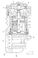
図6、図7に、上記構成の電動式直動アクチュエータ2を用いた電動ブレーキ装置を示す。この電動ブレーキ装置は、車輪(図示せず)と一体に回転するブレーキディスク50と、ブレーキディスク50に対して軸方向に移動不能に車体に固定されたマウンティングブラケット51と、マウンティングブラケット51に対してブレーキディスク50の軸方向と平行にスライド可能に支持されたキャリパボディ52と、ブレーキディスク50を間に挟んで軸方向に対向するインナ側ブレーキパッド53およびアウタ側ブレーキパッド54と、インナ側ブレーキパッド53を軸方向に移動させる電動式直動アクチュエータ2とを有する。インナ側ブレーキパッド53とブレーキディスク50の間には微小なクリアランス55が設けられている。インナ側ブレーキパッド53とアウタ側ブレーキパッド54は、それぞれマウンティングブラケット51によって、軸方向に移動可能かつ周方向に移動不能に保持されている。
6 and 7 show an electric brake device using the electric
キャリパボディ52は、アウタ側ブレーキパッド54の背面に軸方向に対向する爪部56と、ブレーキディスク50の外径側に対向する外殻部57とを有する。外殻部57は、電動式直動アクチュエータ2のハウジング15に一体に形成されている。キャリパボディ52の外殻部57と電動式直動アクチュエータ2のハウジング15とを別体に形成し、その両者をボルト等で一体化してもよい。外輪部材5は、外輪部材5が移動したときに外輪部材5と一体にインナ側ブレーキパッド53も移動するように、インナ側ブレーキパッド53の背面に配置されている。
The
外輪部材5のブレーキディスク50の側の端部には、インナ側ブレーキパッド53の背面に形成された係合凸部58に係合する係合凹部59が形成され、この係合凸部58と係合凹部59の係合によって、外輪部材5は回り止めされている。
At the end of the
この電動ブレーキ装置の動作例を説明する。 An operation example of this electric brake device will be described.
ブレーキをかけるとき、電動モータ3(図1参照)が回転すると、電動モータ3から減速歯車列4を介して回転軸8に回転が伝達し、その回転が遊星ローラねじ式直動機構1で外輪部材5の軸方向移動に変換され、外輪部材5によってインナ側ブレーキパッド53が軸方向前方に押し動かされる。このとき、インナ側ブレーキパッド53がブレーキディスク50に接触するまでの間は、図4に示すように、キャリア14が回転軸8のテーパ面38と摩擦結合しているので、図1に示す外輪部材5が比較的速い速度をもって軸方向に移動する。そのため、インナ側ブレーキパッド53がブレーキディスク50に接触するまでに要する時間が短く、ブレーキの応答性を高めることができる。
When the brake is applied, when the electric motor 3 (see FIG. 1) rotates, the rotation is transmitted from the
その後、インナ側ブレーキパッド53がブレーキディスク50に接触し、インナ側ブレーキパッド53からブレーキディスク50に軸方向荷重が負荷されると、図5に示すように、キャリア14が回転軸8に対して軸方向後方に相対移動し、キャリア14と回転軸8のテーパ面38との摩擦結合が解除されるので、図1に示す外輪部材5の軸方向の移動速度が遅くなるとともに荷重変換率が大きくなり、大きな軸方向荷重が発生する。そのため、インナ側ブレーキパッド53がブレーキディスク50を押圧する力を大きくすることが可能となる。
Thereafter, when the
このように、電動式直動アクチュエータ2を電動ブレーキ装置に使用すると、ブレーキの応答性を高めることと、ブレーキパッドがブレーキディスク50を押圧する力を大きくすることとを両立することが可能となる。
As described above, when the electric
以上のように、この実施形態の遊星ローラねじ式直動機構1は、外輪部材5から対象物に軸方向前方への荷重を負荷していない状態では、回転軸8の外周の摩擦結合部がキャリア14と摩擦結合し、キャリア14と回転軸8の相対回転が制限されるので、外輪部材5の軸方向の移動速度が早くなり、荷重変換率が小さくなる。一方、外輪部材5から対象物に軸方向前方への荷重を負荷した状態では、回転軸8の外周の摩擦結合部とキャリア14との摩擦結合が解除され、キャリア14と回転軸8の相対回転が許容されるので、外輪部材5の軸方向の移動速度が遅くなり、荷重変換率が大きくなる。このように、遊星ローラねじ式直動機構1は、荷重変換率を、外輪部材5から対象物に負荷する軸方向荷重に応じて切り替えることが可能である。
As described above, the planetary roller screw type linear motion mechanism 1 of this embodiment has a friction coupling portion on the outer periphery of the
また、この実施形態の遊星ローラねじ式直動機構1は、回転軸8の外周の遊星ローラ13が転がり接触する円筒面12を研磨等によって高精度に仕上げるときに、センタレス通し研磨等の低コストの加工方法を採用することが可能である。
Further, the planetary roller screw type linear motion mechanism 1 of this embodiment has a low cost such as centerless through polishing when the
すなわち、例えば、図2のテーパ面38を遊星ローラ13が転がり接触する円筒面12に対して軸方向前方(図の左側)に配置し、テーパ内周面40を軸方向前側ディスク19の内周に設けることも可能であるが、このようにすると、テーパ面38が円筒面12よりも大きい外径をもつ構成となるため、遊星ローラ13が転がり接触する円筒面12を研磨等によって仕上げるときに、低コストの加工方法(例えば、センタレス通し研磨)を採用することができず、円筒面12を高精度に仕上げるための加工コストが高くなるという問題がある。
That is, for example, the
これに対し、この実施形態の遊星ローラねじ式直動機構1は、回転軸8の外周のテーパ面38(摩擦結合部)が、遊星ローラ13(円筒面12)に対して軸方向後方に配置されていることから、遊星ローラ13が転がり接触する円筒面12を、回転軸8の最大径部分とすることが可能である。そのため、低コストの加工方法(回転軸8の外周を転がり支持しながら研磨する加工。例えば、センタレス通し研磨)を採用することが可能であり、円筒面12を容易に仕上げることが可能である。なお、センタレス通し研磨は、定位置で回転する研削砥石と、被加工物を間に挟んで研削砥石と対向する位置で回転する調整砥石とを使用し、その研削砥石と調整砥石とで被加工物を軸方向に送りながら被加工物の外周を連続的に研磨する加工方法である。
On the other hand, in the planetary roller screw type linear motion mechanism 1 of this embodiment, the tapered surface 38 (friction coupling portion) on the outer periphery of the
摩擦結合部として、例えば、円筒面12と円筒面39の間をつなぐ軸直交面を採用することも可能であるが、上記実施形態のように、摩擦結合部としてテーパ面38を採用すると、キャリア14と摩擦結合したときに、テーパ面38のくさび作用によって大きな摩擦力を発生することが可能となる。
As the friction coupling portion, for example, an axis orthogonal surface connecting between the
本実施形態では、回転軸8とキャリア14とを摩擦結合する構成としたが、キャリア14と一体となって回転する部材と回転軸8とを摩擦結合する構成としてもよい。例えば、弾性部材35を間座34とスラスト軸受33との間に設け、間座34をキャリア14と一体となって回転するようにし、間座34に回転軸8の外周のテーパ面38と摩擦結合するテーパ内周面40を設けてもよい。
In the present embodiment, the
今回開示された実施の形態はすべての点で例示であって制限的なものではないと考えられるべきである。本発明の範囲は上記した説明ではなくて特許請求の範囲によって示され、特許請求の範囲と均等の意味および範囲内でのすべての変更が含まれることが意図される。 The embodiment disclosed this time should be considered as illustrative in all points and not restrictive. The scope of the present invention is defined by the terms of the claims, rather than the description above, and is intended to include any modifications within the scope and meaning equivalent to the terms of the claims.
1 遊星ローラねじ式直動機構
3 電動モータ
5 外輪部材
8 回転軸
12 円筒面
13 遊星ローラ
14 キャリア
16 螺旋凸条
17 円周溝
35 弾性部材
38 テーパ面
50 ブレーキディスク
53 インナ側ブレーキパッド
DESCRIPTION OF SYMBOLS 1 Planetary roller screw type
Claims (3)
前記円筒面(12)に転がり接触する複数の遊星ローラ(13)と、
その複数の遊星ローラ(13)を自転可能かつ公転可能に保持するキャリア(14)と、
前記複数の遊星ローラ(13)を囲むように配置され、軸方向に移動可能に支持された外輪部材(5)と、
その外輪部材(5)の内周に設けられた螺旋凸条(16)と、
その螺旋凸条(16)と係合するように前記各遊星ローラ(13)の外周に設けられた螺旋溝または円周溝(17)とを有し、
前記螺旋凸条(16)と前記螺旋溝または円周溝(17)との係合によって前記外輪部材(5)が軸方向に移動する遊星ローラねじ式直動機構において、
前記外輪部材(5)に対して対象物に軸方向一方への荷重を負荷したときに受ける軸方向他方への反力により、前記キャリア(14)が前記回転軸(8)に対して軸方向他方に相対移動するように前記キャリア(14)を支持する弾性部材(35)と、
前記回転軸(8)の外周に設けられ、前記キャリア(14)が前記回転軸(8)に対して軸方向他方に相対移動していない場合には、前記キャリア(14)と前記回転軸(8)の相対回転を制限するように前記キャリア(14)と摩擦結合し、前記キャリア(14)が前記回転軸(8)に対して軸方向他方に相対移動した場合には、前記キャリア(14)と前記回転軸(8)の相対回転を許容するように前記キャリア(14)との摩擦結合を解除する、摩擦結合部とを備え、
前記摩擦結合部は、前記遊星ローラ(13)に対して軸方向他方に配置されていることを特徴とする遊星ローラねじ式直動機構。 A rotating shaft (8) having a cylindrical surface (12) on its outer periphery;
A plurality of planetary rollers (13) in rolling contact with the cylindrical surface (12);
A carrier (14) for holding the plurality of planetary rollers (13) in a rotatable and revolving manner;
An outer ring member (5) disposed so as to surround the plurality of planetary rollers (13) and supported so as to be movable in the axial direction;
A spiral ridge (16) provided on the inner periphery of the outer ring member (5);
A spiral groove or a circumferential groove (17) provided on the outer periphery of each planetary roller (13) so as to engage with the spiral protrusion (16);
In the planetary roller screw type linear motion mechanism in which the outer ring member (5) moves in the axial direction by the engagement of the spiral protrusion (16) and the spiral groove or the circumferential groove (17),
The carrier (14) is axially moved with respect to the rotating shaft (8) by a reaction force to the other axial direction received when a load is applied to the object in the axial direction on the outer ring member (5). An elastic member (35) that supports the carrier (14) so as to move relative to the other;
When provided on the outer periphery of the rotating shaft (8) and the carrier (14) is not moved relative to the rotating shaft (8) in the other axial direction, the carrier (14) and the rotating shaft ( 8) When the carrier (14) is frictionally coupled with the carrier (14) so as to limit the relative rotation of the carrier (14) and the carrier (14) moves relative to the other axis in the axial direction, the carrier (14) ) And the friction coupling part for releasing the frictional coupling with the carrier (14) so as to allow relative rotation of the rotating shaft (8),
The planetary roller screw type linear motion mechanism characterized in that the frictional coupling portion is disposed on the other side in the axial direction with respect to the planetary roller (13).
前記遊星ローラねじ式直動機構(1)の回転軸(8)を回転駆動する電動モータ(3)と、
前記遊星ローラねじ式直動機構(1)の外輪部材(5)と一体に移動するブレーキパッド(53)と、
前記ブレーキパッド(53)に対向して配置されたブレーキディスク(50)と、
を有する電動ブレーキ装置。 The planetary roller screw type linear motion mechanism (1) according to claim 1 or 2,
An electric motor (3) for rotationally driving the rotating shaft (8) of the planetary roller screw type linear motion mechanism (1);
A brake pad (53) that moves integrally with the outer ring member (5) of the planetary roller screw type linear motion mechanism (1);
A brake disc (50) disposed opposite the brake pad (53);
Electric brake device having
Priority Applications (5)
| Application Number | Priority Date | Filing Date | Title |
|---|---|---|---|
| JP2016119661A JP6758937B2 (en) | 2016-06-16 | 2016-06-16 | Planetary roller screw type linear motion mechanism and electric braking device |
| US16/309,755 US10808781B2 (en) | 2016-06-16 | 2017-05-24 | Electric linear motion actuator and electromechanical brake system |
| CN201780036571.2A CN109312837B (en) | 2016-06-16 | 2017-05-24 | Electric direct-acting actuator and electric braking device |
| PCT/JP2017/019404 WO2017217202A1 (en) | 2016-06-16 | 2017-05-24 | Electric linear actuator and electric brake device |
| EP17813104.1A EP3473891A4 (en) | 2016-06-16 | 2017-05-24 | ELECTRICAL LINEAR ACTUATOR AND ELECTRIC BRAKE DEVICE |
Applications Claiming Priority (1)
| Application Number | Priority Date | Filing Date | Title |
|---|---|---|---|
| JP2016119661A JP6758937B2 (en) | 2016-06-16 | 2016-06-16 | Planetary roller screw type linear motion mechanism and electric braking device |
Publications (2)
| Publication Number | Publication Date |
|---|---|
| JP2017223301A true JP2017223301A (en) | 2017-12-21 |
| JP6758937B2 JP6758937B2 (en) | 2020-09-23 |
Family
ID=60687953
Family Applications (1)
| Application Number | Title | Priority Date | Filing Date |
|---|---|---|---|
| JP2016119661A Active JP6758937B2 (en) | 2016-06-16 | 2016-06-16 | Planetary roller screw type linear motion mechanism and electric braking device |
Country Status (1)
| Country | Link |
|---|---|
| JP (1) | JP6758937B2 (en) |
Cited By (2)
| Publication number | Priority date | Publication date | Assignee | Title |
|---|---|---|---|---|
| CN109630635A (en) * | 2019-01-21 | 2019-04-16 | 洛阳德美机械有限公司 | A kind of planetary roller screw transmission system |
| CN113272577A (en) * | 2019-02-12 | 2021-08-17 | 舍弗勒技术股份两合公司 | Planetary roller screw and actuator for a rear axle steering of a motor vehicle comprising such a planetary roller screw |
Citations (3)
| Publication number | Priority date | Publication date | Assignee | Title |
|---|---|---|---|---|
| JP2012057681A (en) * | 2010-09-07 | 2012-03-22 | Ntn Corp | Electric linear actuator and electric disk brake device |
| JP2012149747A (en) * | 2011-01-21 | 2012-08-09 | Ntn Corp | Electric linear motion actuator and electric disc brake device |
| JP2014206286A (en) * | 2014-08-06 | 2014-10-30 | Ntn株式会社 | Electric disc brake device |
-
2016
- 2016-06-16 JP JP2016119661A patent/JP6758937B2/en active Active
Patent Citations (3)
| Publication number | Priority date | Publication date | Assignee | Title |
|---|---|---|---|---|
| JP2012057681A (en) * | 2010-09-07 | 2012-03-22 | Ntn Corp | Electric linear actuator and electric disk brake device |
| JP2012149747A (en) * | 2011-01-21 | 2012-08-09 | Ntn Corp | Electric linear motion actuator and electric disc brake device |
| JP2014206286A (en) * | 2014-08-06 | 2014-10-30 | Ntn株式会社 | Electric disc brake device |
Cited By (4)
| Publication number | Priority date | Publication date | Assignee | Title |
|---|---|---|---|---|
| CN109630635A (en) * | 2019-01-21 | 2019-04-16 | 洛阳德美机械有限公司 | A kind of planetary roller screw transmission system |
| CN113272577A (en) * | 2019-02-12 | 2021-08-17 | 舍弗勒技术股份两合公司 | Planetary roller screw and actuator for a rear axle steering of a motor vehicle comprising such a planetary roller screw |
| CN113272577B (en) * | 2019-02-12 | 2024-05-10 | 舍弗勒技术股份两合公司 | Planetary roller screw and actuator for a motor vehicle comprising a rear axle steering device of said planetary roller screw |
| US12012157B2 (en) | 2019-02-12 | 2024-06-18 | Schaeffler Technologies AG &Co. KG | Planetary roller screw and actuator for a rear axle steering of a motor vehicle comprising such a planetary roller screw |
Also Published As
| Publication number | Publication date |
|---|---|
| JP6758937B2 (en) | 2020-09-23 |
Similar Documents
| Publication | Publication Date | Title |
|---|---|---|
| JP5282998B2 (en) | Electric linear actuator and electric brake device | |
| JP5376279B2 (en) | Electric linear actuator and electric brake device | |
| CN108071761B (en) | Motion conversion mechanism and electric brake actuator using the motion conversion mechanism | |
| JP2017124706A (en) | Electric brake device | |
| JP2014047845A (en) | Electrically-driven linear actuator and electrically-driven disc braking device | |
| CN109312837B (en) | Electric direct-acting actuator and electric braking device | |
| JP2017096362A (en) | Electric linear actuator and electric brake device | |
| JP2012057681A (en) | Electric linear actuator and electric disk brake device | |
| JP5585865B2 (en) | Electric linear actuator and electric brake device | |
| JP6758937B2 (en) | Planetary roller screw type linear motion mechanism and electric braking device | |
| JP2011179542A (en) | Electromotive linear actuator and electromotive disc brake | |
| JP2018013167A (en) | Planetary roller screw type direct motion mechanism and electric brake device | |
| JP5946399B2 (en) | Electric disc brake device | |
| JP2017020565A (en) | Floating-type electric disc brake device | |
| JP2018009660A (en) | Planetary roller screw type linear motion mechanism and electric brake device | |
| JP2014214752A (en) | Electric disc brake device | |
| JP2017180760A (en) | Planetary roller screw type linear motion mechanism and electric brake device | |
| JP2016109281A (en) | Brake device | |
| JP2017180506A (en) | Planetary roller screw type linear motion mechanism and electric brake device | |
| JP6739262B2 (en) | Electric linear actuator and electric brake device | |
| JP2015232370A (en) | Electric linear actuator and electric brake device | |
| JP4988280B2 (en) | Electric linear actuator and electric brake device | |
| JP4847427B2 (en) | Electric brake device | |
| JP2008089084A (en) | Electric linear actuator and electric brake device | |
| JP6999606B2 (en) | Electric linear actuator |
Legal Events
| Date | Code | Title | Description |
|---|---|---|---|
| A621 | Written request for application examination |
Free format text: JAPANESE INTERMEDIATE CODE: A621 Effective date: 20190527 |
|
| A131 | Notification of reasons for refusal |
Free format text: JAPANESE INTERMEDIATE CODE: A131 Effective date: 20200421 |
|
| A521 | Request for written amendment filed |
Free format text: JAPANESE INTERMEDIATE CODE: A523 Effective date: 20200605 |
|
| TRDD | Decision of grant or rejection written | ||
| A01 | Written decision to grant a patent or to grant a registration (utility model) |
Free format text: JAPANESE INTERMEDIATE CODE: A01 Effective date: 20200804 |
|
| A61 | First payment of annual fees (during grant procedure) |
Free format text: JAPANESE INTERMEDIATE CODE: A61 Effective date: 20200902 |
|
| R150 | Certificate of patent or registration of utility model |
Ref document number: 6758937 Country of ref document: JP Free format text: JAPANESE INTERMEDIATE CODE: R150 |
|
| R250 | Receipt of annual fees |
Free format text: JAPANESE INTERMEDIATE CODE: R250 |
|
| R250 | Receipt of annual fees |
Free format text: JAPANESE INTERMEDIATE CODE: R250 |
|
| R250 | Receipt of annual fees |
Free format text: JAPANESE INTERMEDIATE CODE: R250 |