JP2017227100A - Earth-retaining timbering - Google Patents
Earth-retaining timbering Download PDFInfo
- Publication number
- JP2017227100A JP2017227100A JP2016126114A JP2016126114A JP2017227100A JP 2017227100 A JP2017227100 A JP 2017227100A JP 2016126114 A JP2016126114 A JP 2016126114A JP 2016126114 A JP2016126114 A JP 2016126114A JP 2017227100 A JP2017227100 A JP 2017227100A
- Authority
- JP
- Japan
- Prior art keywords
- suspension
- mountain retaining
- support
- pair
- cut
- Prior art date
- Legal status (The legal status is an assumption and is not a legal conclusion. Google has not performed a legal analysis and makes no representation as to the accuracy of the status listed.)
- Pending
Links
Images


Landscapes
- Bulkheads Adapted To Foundation Construction (AREA)
Abstract
Description
本発明は、対向する一対の山留壁間に棚杭を設置することなく切梁が架設された山留め支保工に関する。 The present invention relates to a mountain retaining support in which a beam is installed without installing a shelf pile between a pair of opposing mountain retaining walls.
従来より、切梁を用いた山留め支保工が知られている。
例えば、この山留め支保工は、互いに対向する一対の山留壁と、この一対の山留壁同士の間に架設された切梁と、この切梁の途中に配置されてこの切梁を支持する棚杭(中間杭)と、を備える。
この山留め支保工では、切梁の中間位置に棚杭を設置することで、対向する山留壁同士の間隔が長い場合であっても、切梁を架設することができる。しかし、その反面、掘削箇所に複数の棚杭を設けることになるため、切梁の直下では、掘削作業の作業性が低下する、という問題があった。
Conventionally, a mountain retaining support using a cut beam is known.
For example, the mountain retaining support is a pair of mountain retaining walls facing each other, a cut beam constructed between the pair of mountain retaining walls, and disposed in the middle of the beam to support the cut beam. A shelf pile (intermediate pile).
In this mountain retaining support, by installing a shelf pile at the middle position of the beam, it is possible to install the beam even if the distance between the opposing mountain retaining walls is long. However, on the other hand, since a plurality of shelf piles are provided at the excavation site, there is a problem that the workability of the excavation work is deteriorated immediately below the cutting beam.
そこで、以下のような山留め支保工が提案されている。
特許文献1には、互いに対向する山留壁間に複数段の切梁が架設され、最上段の切梁から下段の切梁を吊り下げ支持する山留め支保工が示されている。
特許文献2には、地下躯体の逆打ち工法において、先行して構築した1階床スラブから切梁を吊り下げ支持する山留め支保工が示されている。
Therefore, the following mountain support works have been proposed.
Japanese Patent Application Laid-Open No. H10-228561 shows a mountain retaining support in which a plurality of stages of beams are installed between mountain walls facing each other and a lower beam is suspended and supported from the uppermost beam.
ところで、特許文献1、2の山留め支保工では、最上段の切梁や1階床スラブから下段の切梁を吊り下げ支持するため、地震時には、この最上段の切梁や1階床スラブに大きな
鉛直荷重が作用する場合があり、山留め支保工の安定性を確保できないおそれがあった。
また、特許文献2の山留め支保工では、1階床スラブを支持するための構真柱が掘削箇所に設ける必要があるため、依然として、掘削作業に加えて、躯体工事においても施工性が低下する、という問題があった。
By the way, in the mountain retaining support of
In addition, in the mountain retaining work of
本発明は、掘削作業の効率を向上させつつ、支保工の安定性を確保できる、山留め支保工を提供することを目的とする。 An object of the present invention is to provide a mountain support that can secure the stability of the support while improving the efficiency of excavation work.
本発明者らは、対向する一対の山留壁間に架設する山留め支保工として、山留壁の上方に設置した切梁吊桁により下方側に架設される切梁を吊り下げ支持することで、切梁の中間位置に棚杭を設けることなく切梁を支持できる点に着目し、本願発明の山留め支保工の発明に至った。 The present inventors have suspended and supported a cut beam installed on the lower side by a cut beam suspension girder installed above the mountain retaining wall as a mountain retaining support constructed between a pair of opposing mountain retaining walls. Focusing on the fact that the beam can be supported without providing a shelf pile at the middle position of the beam, the inventors have reached the invention of the mountain support structure of the present invention.
第1の発明の山留め支保工(例えば、後述の山留め支保工1、1A、1B)は、対向する一対の山留壁(例えば、後述の山留壁10、10A)の間に設けられた切梁(例えば、後述の切梁20)を備える山留め支保工であって、前記一対の山留壁の上方でかつ当該一対の山留壁の少なくとも一方に跨がって設けられた切梁吊桁(例えば、後述の切梁吊桁30、30A)と、当該切梁吊桁から吊り下げ支持されて前記切梁を支持する吊架台(例えば、後述の吊架台40、40B)と、を備えることを特徴とする。
In the first aspect of the present invention, the retaining support (e.g., later-described
この発明によれば、吊架台を介して切梁を切梁吊桁から吊り下げ支持したので、切梁を棚杭で支持する必要がなく、切梁の直下に広い掘削空間を確保でき、掘削作業の効率を向上できる。
本願発明の山留め支保工は、対向する一対の山留壁同士を切梁吊桁と切梁によって支持するものであり、切梁単体のみで山留壁を支持する必要がないので、切梁を大断面とする必要はなく、施工性に優れている。
また、切梁を吊り下げ支持する切梁吊桁を、少なくとも一方の山留壁に跨がって設けたので、切梁吊桁の端部が山留壁の背面側の地盤に支持されることになり、地震時の揺れによって切梁吊桁に大きな鉛直荷重がかかっても、切梁吊桁および山留壁の背面の地盤によって山留め支保工の安定性を確保できる。
According to the present invention, since the beam is suspended and supported from the beam suspension beam via the suspension frame, it is not necessary to support the beam with the shelf pile, and a wide excavation space can be secured immediately below the beam, Work efficiency can be improved.
The mountain retaining support of the present invention supports a pair of opposing mountain retaining walls with a beam suspension girder and a beam, and it is not necessary to support the mountain retaining wall with only a single beam. It is not necessary to have a large cross section and is excellent in workability.
Moreover, since the beam suspension girder for hanging and supporting the beam is provided across at least one mountain retaining wall, the end of the beam suspension beam is supported by the ground on the back side of the mountain retaining wall. Therefore, even if a large vertical load is applied to the beam suspension girder due to the shaking at the time of the earthquake, the stability of the mountain support can be secured by the ground behind the beam suspension beam and the mountain retaining wall.
第2の発明の山留め支保工は、前記切梁吊桁は、水平方向に所定間隔おきに複数設けられ、前記吊架台は、隣接する切梁吊桁同士を連結することを特徴とする。 According to a second aspect of the present invention, a plurality of the beam suspension girders are provided at predetermined intervals in the horizontal direction, and the suspension base connects adjacent beam suspension girders.
この発明によれば、切梁吊桁同士を吊架台で連結することで、山留壁に作用する地震荷重に対して複数の切梁吊桁で抵抗でき、山留め支保工の耐震性能を高めることができる。 According to this invention, by connecting the beam suspension girders with a suspension stand, it is possible to resist the seismic load acting on the mountain retaining wall with a plurality of beam suspension girders, and to improve the earthquake resistance performance of the mountain retaining support. Can do.
第3の発明の山留め支保工は、前記吊架台は、前記切梁吊桁の上面に配置されて当該切梁吊桁同士の間に架設されて接合された上側水平材(例えば、後述の上側水平材41)と、前記切梁の下面または上面に配置されて当該切梁同士の間に架設されて接合された下側水平材(例えば、後述の42)と、前記上側水平材と前記下側水平材とを連結する吊材(例えば、後述の吊材43)と、を備えることを特徴とする。
According to a third aspect of the present invention, the suspension support is arranged on the upper surface of the beam suspension girder, and is mounted on the upper horizontal member between the beam suspension beams (for example, the upper horizontal member described later). A horizontal member 41), a lower horizontal member (for example, 42 described later) disposed on the lower surface or the upper surface of the beam and laid between the beams, and the upper horizontal member and the lower beam. And a suspension member (for example, a
本発明によれば、吊架台は、上側水平材、下側水平材および吊材を含んで構成され、この吊架台によって切梁吊桁と切梁とが連結されて、切梁吊桁から切梁が吊り下げ支持される。したがって、切梁吊桁と切梁とは、容易に長さが変更可能な吊材によって連結されるとともに、切梁吊桁および切梁は、吊材と交差する方向に設置された上側水平材および下側水平材により互いに接合されるので、切梁吊桁と切梁とが一体化した耐震安全性に優れた架設体が形成される。 According to the present invention, the suspension base is configured to include the upper horizontal member, the lower horizontal member, and the suspension member, and the beam suspension girder and the beam are connected by the suspension platform, and the suspension beam is cut from the beam suspension beam. The beam is suspended and supported. Therefore, the cut beam suspension girder and the cut beam are connected by a suspension material whose length can be easily changed, and the cut beam suspension girder and the cut beam are upper horizontal members installed in a direction intersecting with the suspension material. And since it is joined to each other by the lower horizontal member, a construction body excellent in seismic safety in which the beam suspension beam and the beam are integrated is formed.
本発明によれば、対向する一対の山留壁の上方に切梁吊桁を設置し、その切梁吊桁より切梁を吊り下げ支持することで、切梁の中間位置に棚杭を設置する必要がない。よって、掘削作業の効率を向上させつつ、支保工の安定性を確保できる。 According to the present invention, by installing a beam suspension girder above a pair of opposing mountain retaining walls and hanging and supporting the beam from the beam suspension girder, a shelf pile is installed at an intermediate position of the beam There is no need to do. Therefore, it is possible to secure the stability of the support work while improving the efficiency of the excavation work.
本願発明の山留め支保工は、山留壁同士の間に架設される切梁の中間に棚杭を設ける必要はなく、山留壁の上方に切梁吊桁を設置し、その切梁吊桁より切梁を吊り下げ支持させた架設体である。
実施形態は、対向する一対の山留壁の背面側の地盤上に切梁吊桁を設置し、その切梁吊桁より切梁を支持した第1実施形態(図1〜図3)と、一方の山留壁の上方のみに切梁吊桁を設置した第2実施形態(図5)と、切梁吊桁と切梁とを斜材で連結した第3実施形態(図5)と、がある。
The mountain retaining support of the present invention does not require a shelf pile in the middle of the beams built between the retaining walls, and installs a suspended beam girder above the retaining wall, It is a erected body in which a cut beam is suspended and supported.
The embodiment is a first embodiment (FIGS. 1 to 3) in which a beam suspension beam is installed on the ground on the back side of a pair of opposing mountain retaining walls, and the beam is supported by the beam suspension beam, A second embodiment (FIG. 5) in which a beam suspension girder is installed only above one mountain retaining wall, and a third embodiment (FIG. 5) in which the beam suspension beam and the beam are connected with diagonal members; There is.
以下、本発明の実施形態を図面に基づいて説明する。なお、以下の実施形態の説明にあたって、同一構成要件については同一符号を付し、その説明を省略もしくは簡略化する。
〔第1実施形態〕
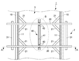
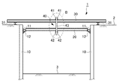
図1は、本発明の第1実施形態に係る山留め支保工1の部分平面図である。図2は、図1のA−A縦断面図である。図3は、図1および図2の破線Bで示す部分の斜視図である。
Hereinafter, embodiments of the present invention will be described with reference to the drawings. In the following description of the embodiments, the same constituent elements are denoted by the same reference numerals, and the description thereof is omitted or simplified.
[First Embodiment]
FIG. 1 is a partial plan view of a mountain retaining structure 1 according to the first embodiment of the present invention. FIG. 2 is a vertical cross-sectional view taken along the line AA in FIG. FIG. 3 is a perspective view of a portion indicated by a broken line B in FIGS. 1 and 2.
山留め支保工1は、地盤面2の所定箇所を床付面3に至るまで掘削するために構築される。この山留め支保工1は、互いに対向する一対の山留壁10と、一対の山留壁10同士の間に水平方向に所定間隔おきに架設された切梁20と、一対の山留壁10の上方でかつ一対の山留壁10の両方に跨がって設けられた切梁吊桁30と、切梁吊桁30から吊り下げ支持されて切梁20を支持する吊架台40と、を備える。
The mountain retaining support 1 is constructed to excavate a predetermined portion of the
山留壁10は、SMW(Soil Mixing Wall)工法、親杭鋼矢板工法、シートパイル工法などにより構築される。この山留壁10の内壁面には、水平方向に延びる腹起し11が、腹起しブラケット12を介して取り付けられている。
切梁20は、H形鋼であり、この腹起し11同士の間に架設されている。また、切梁20と腹起し11との間には、切梁20に対して斜めに延びる火打ち21が架設されている。
The
The
切梁吊桁30は、H形鋼であり、これら切梁20の直上に、水平方向に所定間隔おきに複数設けられている。山留壁10の背面側の地盤面2上には、H形鋼である支持部材31が配置されており、この切梁吊桁30の両端部は、これら支持部材31の上に載置されている。これにより、切梁吊桁30は、両端部で地盤面2に支持されている。また、支持部材31は、地盤面2にアンカー筋で固定されている。切梁吊桁30と支持部材31との間は、地震荷重が作用した際に、上向きの外力に抵抗できるように、ボルト接合されている。
The
吊架台40は、切梁吊桁30の上に配置されて切梁吊桁30同士の間に架設されて接合された上側水平材41と、切梁20の下に配置されて切梁20同士の間に架設されて接合された下側水平材42と、鉛直方向に延びて上側水平材41と下側水平材42とを連結する吊材43と、隣り合う吊材43同の間に斜めに設けられたブレース44と、を備える。
The
吊材43は、一対のH形鋼であり、この一対のH形鋼は、切梁20の両側に配置されている。
上側水平材41および下側水平材42は、互いに背中合わせに配置された一対の溝形鋼であり、この一対の溝形鋼は、吊材43を両側から挟んで配置されている。このように、吊材43を両側から挟むように上側水平材41および下側水平材42を設けたので、地震荷重によって吊材43が上側水平材41や下側水平材42から脱落するのを防止できる。
ブレース44は、互いに交差するように配置された一対の山形鋼で構成されている。
The
The upper
The
上側水平材41は、各切梁吊桁30にボルト50で固定され、これにより、切梁吊桁30同士を連結している。また、吊材43は、この上側水平材41にボルト51で固定されている。
下側水平材42は、吊材43にボルト52で固定されており、切梁20は、この下側水平材42にUボルト53で取り付けられている。
The upper
The lower
本実施形態によれば、以下のような効果がある。
(1)吊架台40を介して切梁20を切梁吊桁30から吊り下げ支持したので、切梁20を棚杭で支持する必要がなく、切梁20の直下に広い掘削空間を確保でき、掘削作業の効率を向上できる。このように、本願発明の山留め支保工1では、掘削空間内に棚杭を設置しないので、作業効率を低下させることなく、建物の地下躯体を構築できる。
また、山留壁10同士の間に切梁のみを単独で架設する構造ではないので、切梁20を大断面とする必要がなく、施工性に優れている。
また、切梁20を吊り下げ支持する切梁吊桁30を、一対の山留壁10の両方に跨がって設けたので、切梁吊桁30の両端部が山留壁10の背面側の地盤面2に支持されることになり、地震時の揺れによって切梁吊桁30に大きな鉛直荷重がかかっても、山留め支保工1の安定性を確保できる。
対向する一対の山留壁は、切梁吊桁30と切梁20とが連結された架設体である山留め支保工1によって支持されるため、切梁単体のみを大断面化する必要はなく、施工性や鋼材価格を考慮して、市場品を適宜組み合わせて切梁吊桁30や切梁20として用いることができる。
According to this embodiment, there are the following effects.
(1) Since the
Moreover, since it is not the structure which installs only a cut beam between the
Further, since the
Since the pair of opposing mountain retaining walls are supported by the mountain retaining support 1 that is a construction in which the
(2)切梁吊桁30同士を吊架台40の上側水平材41で連結することで、山留壁10に作用する地震荷重に対して複数の切梁吊桁30で抵抗でき、山留め支保工1の耐震性能を高めることができる。
(2) By connecting the
(3)吊架台40は、上側水平材41、下側水平材42および吊材43を含んで構成されるので、吊材43の長さを適宜調整することで、切梁吊桁30と切梁20を接合することができる。また、吊架台40を少ない部材点数でかつ簡素な構造としたので、低コストかつ確実に、切梁吊桁30から切梁20を吊り下げ支持できる。
(3) Since the
〔第2実施形態〕
図4は、本発明の第2実施形態に係る山留め支保工1Aの縦断面図である。
本実施形態では、切梁吊桁30Aが一対の山留壁10の一方のみに跨がって設けられる点が、第1実施形態と異なる。
すなわち、図4中右側の山留壁10Aは、山留壁10よりも上方まで延びており、山留壁10Aには、水平方向に延びる腹起し13が、腹起しブラケット14を介して取り付けられている。切梁吊桁30Aの図4中右側の端部は、この腹起し13に接合されている。
[Second Embodiment]
FIG. 4 is a vertical cross-sectional view of a
The present embodiment is different from the first embodiment in that the cut
That is, the
本実施形態によれば、上述の(1)〜(3)の効果に加えて、以下のような効果がある。
(4)山留壁10、10Aの一方が高い場合でも、切梁吊桁30Aを架設して山留め支保工1Aを構築できる。
According to this embodiment, in addition to the effects (1) to (3) described above, the following effects can be obtained.
(4) Even when one of the
〔第3実施形態〕
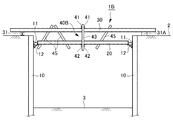
図5は、本発明の第3実施形態に係る山留め支保工1Bの縦断面図である。
本実施形態では、吊架台40Bの構成が第1実施形態と異なる。
すなわち、吊架台40Bは、第1実施形態の吊架台40の構成に加えて、鉛直方向に対して斜めに延びて切梁吊桁30と切梁20とを直接連結する斜材45を備える。
[Third Embodiment]
FIG. 5 is a longitudinal cross-sectional view of a
In the present embodiment, the configuration of the
That is, the
本実施形態では、地盤面2上に構築された上面がフラット状のコンクリート平板を、支持部材31Aとして用いる。この支持部材31Aは、地盤面2にアンカー筋で固定されており、これにより、支持部材31Aや切梁吊桁30に作用する上向きの外荷重に抵抗できる。また、支持部材31Aをコンクリート平板とすることで、支持部材31Aを地盤面2から任意の高さに容易に設定できる。
In the present embodiment, a concrete flat plate having a flat upper surface constructed on the
また、斜材45は、切梁吊桁30と切梁20との間に複数設けられる。なお、この斜材としては、切梁吊桁30および切梁20を挟んで一対の鋼材同士を背中合わせに配置してもよい。このようにすれば、切梁吊桁30と切梁20との間の一体性が高められ、高い耐震安全性を確保できる。
Further, a plurality of
本実施形態によれば、上述の(1)〜(3)の効果に加えて、以下のような効果がある。
(5)斜材45により切梁吊桁30と切梁20と連結したので、地震による揺れに対して、より確実に抵抗でき、耐震性能を向上できる。
According to this embodiment, in addition to the effects (1) to (3) described above, the following effects can be obtained.
(5) Since the cut
なお、本発明は前記実施形態に限定されるものではなく、本発明の目的を達成できる範囲での変形、改良等は本発明に含まれるものである。
また、上述の各実施形態では、吊材43やブレース44を一対ずつ設けたが、これに限らず、吊材43やブレース44の本数は、各部材に作用する外荷重や負担応力に基づいて、適宜設定されてよい。
It should be noted that the present invention is not limited to the above-described embodiment, and modifications, improvements, etc. within a scope that can achieve the object of the present invention are included in the present invention.
Moreover, in each above-mentioned embodiment, although the
1、1A、1B…山留め支保工 2…地盤面 3…床付面
10、10A…山留壁 11…腹起し 12…腹起しブラケット
13…腹起し 14…腹起しブラケット 20…切梁
21…火打ち 30、30A…切梁吊桁 31、31A…支持部材
40、40B…吊架台 41…上側水平材 42…下側水平材
43…吊材 44…ブレース 45…斜材
50、51、52…ボルト 53…Uボルト
DESCRIPTION OF
Claims (3)
前記一対の山留壁の上方でかつ当該一対の山留壁の少なくとも一方に跨がって設けられた切梁吊桁と、
当該切梁吊桁から吊り下げ支持されて前記切梁を支持する吊架台と、を備えることを特徴とする山留め支保工。 It is a mountain retaining support provided with a cutting beam provided between a pair of opposing mountain retaining walls,
A beam suspension girder provided above the pair of mountain retaining walls and straddling at least one of the pair of mountain retaining walls,
And a suspension stand that is supported by hanging from the beam suspension girder and supports the beam.
前記吊架台は、隣接する切梁吊桁同士を連結することを特徴とする請求項1に記載の山留め支保工。 A plurality of the beam suspension girders are provided at predetermined intervals in the horizontal direction,
The mountain support structure according to claim 1, wherein the suspension base connects adjacent beam suspension girders.
前記切梁の下面または上面に配置されて当該切梁同士の間に架設されて接合された下側水平材と、
前記上側水平材と前記下側水平材とを連結する吊材と、を備えることを特徴とする請求項1または2に記載の山留め支保工。 The suspension base is disposed on the upper surface of the beam suspension girder and is installed between the beam suspension girders and joined to the upper horizontal member,
A lower horizontal member disposed on the lower surface or the upper surface of the beam and erected between the beams and joined;
The mountain support structure according to claim 1 or 2, further comprising a suspension member that connects the upper horizontal member and the lower horizontal member.
Priority Applications (1)
| Application Number | Priority Date | Filing Date | Title |
|---|---|---|---|
| JP2016126114A JP2017227100A (en) | 2016-06-25 | 2016-06-25 | Earth-retaining timbering |
Applications Claiming Priority (1)
| Application Number | Priority Date | Filing Date | Title |
|---|---|---|---|
| JP2016126114A JP2017227100A (en) | 2016-06-25 | 2016-06-25 | Earth-retaining timbering |
Publications (1)
| Publication Number | Publication Date |
|---|---|
| JP2017227100A true JP2017227100A (en) | 2017-12-28 |
Family
ID=60891147
Family Applications (1)
| Application Number | Title | Priority Date | Filing Date |
|---|---|---|---|
| JP2016126114A Pending JP2017227100A (en) | 2016-06-25 | 2016-06-25 | Earth-retaining timbering |
Country Status (1)
| Country | Link |
|---|---|
| JP (1) | JP2017227100A (en) |
Cited By (2)
| Publication number | Priority date | Publication date | Assignee | Title |
|---|---|---|---|---|
| KR20210130725A (en) * | 2019-02-26 | 2021-11-01 | 지난 레일 트랜지트 그룹 컴퍼니 리미티드 | Reinforcement device and method for local freezing reinforcement in deep pits in gravel strata containing large amounts of water |
| CN114032919A (en) * | 2021-11-30 | 2022-02-11 | 天津建工科技有限公司 | Assembled suspension supporting device and method for foundation pit supporting |
-
2016
- 2016-06-25 JP JP2016126114A patent/JP2017227100A/en active Pending
Cited By (3)
| Publication number | Priority date | Publication date | Assignee | Title |
|---|---|---|---|---|
| KR20210130725A (en) * | 2019-02-26 | 2021-11-01 | 지난 레일 트랜지트 그룹 컴퍼니 리미티드 | Reinforcement device and method for local freezing reinforcement in deep pits in gravel strata containing large amounts of water |
| KR102709067B1 (en) * | 2019-02-26 | 2024-09-25 | 지난 레일 트랜지트 그룹 컴퍼니 리미티드 | Method for constructing deep pit local freezing reinforcement in gravel layer containing a large amount of moisture |
| CN114032919A (en) * | 2021-11-30 | 2022-02-11 | 天津建工科技有限公司 | Assembled suspension supporting device and method for foundation pit supporting |
Similar Documents
| Publication | Publication Date | Title |
|---|---|---|
| JP2013256793A (en) | Construction method for underground structure, and underground structure | |
| JP2011157812A (en) | Retaining wall and construction method therefor | |
| JP6650257B2 (en) | Mountain retaining structure and construction method thereof | |
| JP6654428B2 (en) | Building method using reverse construction method | |
| JP2017082532A (en) | Braced column frame | |
| JP4812324B2 (en) | Retaining wall and its construction method | |
| JP2013015015A (en) | Structure and construction method for earth retaining wall | |
| JP6357366B2 (en) | Horizontal movement restraint method | |
| JP2020176380A (en) | Foundation structure of building | |
| JP2018071080A (en) | Suspension stand for temporary scaffolding | |
| JP6329824B2 (en) | Yamato member and road surface lining method | |
| JP6774774B2 (en) | Pile foundation structure | |
| JP2016132948A (en) | Connection structure | |
| JP2003268770A (en) | Earth retaining construction method and reinforcing structure of sheet pile used for this construction method | |
| JP6868881B2 (en) | Foundation structure and its foundation construction method | |
| JP5592309B2 (en) | Oblique beam mounting structure | |
| JP7310406B2 (en) | Support structure for earth retaining wall and method for supporting earth retaining wall | |
| JP5322214B2 (en) | Foundation reinforcement method for existing wooden houses | |
| JP2006316495A (en) | Foundation structure of bridge pier and its construction method | |
| JP6368562B2 (en) | Pile foundation structure | |
| KR102307510B1 (en) | Temporary earth retaining structure and Construction method using the same | |
| KR102065941B1 (en) | Method for constructing soil retaining wall structure using h-pile | |
| JP4634702B2 (en) | Seismic reinforcement structure for buildings, seismic reinforcement method for buildings | |
| JP4432581B2 (en) | Building structure that can change floor height | |
| JP6496464B2 (en) | Joint structure of ready-made pillar and footing |