JP2017227182A - diesel engine - Google Patents
diesel engine Download PDFInfo
- Publication number
- JP2017227182A JP2017227182A JP2016124424A JP2016124424A JP2017227182A JP 2017227182 A JP2017227182 A JP 2017227182A JP 2016124424 A JP2016124424 A JP 2016124424A JP 2016124424 A JP2016124424 A JP 2016124424A JP 2017227182 A JP2017227182 A JP 2017227182A
- Authority
- JP
- Japan
- Prior art keywords
- doc
- exhaust
- diesel engine
- dpf
- temperature
- Prior art date
- Legal status (The legal status is an assumption and is not a legal conclusion. Google has not performed a legal analysis and makes no representation as to the accuracy of the status listed.)
- Granted
Links
Images


Landscapes
- Control Of Throttle Valves Provided In The Intake System Or In The Exhaust System (AREA)
- Exhaust Gas After Treatment (AREA)
- Processes For Solid Components From Exhaust (AREA)
- Exhaust Gas Treatment By Means Of Catalyst (AREA)
Abstract
Description
本発明は、ディーゼルエンジンに関し、詳しくは、DOC再生処理での消費電力を小さくすることができるディーゼルエンジンに関する。 The present invention relates to a diesel engine, and more particularly to a diesel engine that can reduce power consumption in a DOC regeneration process.
従来、エンジンECUと、DOCを備え、エンジンECUの指令で、エンジン運転中、DOC再生処理がなされ、DOC再生処理では、DOCに詰まった未燃焼堆積物が除去されるように構成された、ディーゼルエンジンの発明がある(例えば、特許文献1参照)。 Conventionally, a diesel engine equipped with an engine ECU and a DOC is configured so that a DOC regeneration process is performed during engine operation according to a command of the engine ECU, and in the DOC regeneration process, unburned deposits clogged in the DOC are removed. There is an invention of an engine (see, for example, Patent Document 1).
この種の発明では、DOC再生処理によりDOCの機能を回復することができる利点がある。 In this kind of invention, there is an advantage that the function of the DOC can be recovered by the DOC regeneration process.
特許文献1の発明では、DOCから離間した位置に配置された電気ヒータを備え、DOC再生処理では、電気ヒータが発熱されるように構成されている。
The invention of
《問題点》 DOC再生処理での消費電力が大きくなる。
特許文献1の発明では、電気ヒータはDOCから離間した位置に配置されているため、DOC再生処理では、電気ヒータの熱は排気を介してDOCに詰った未燃焼堆積物に間接的に伝達され、電気ヒータから未燃焼堆積物への熱の伝達ロスが大きくなる。このため、特許文献1の発明では、未燃焼堆積物の焼却に対する電気ヒータの熱効率が低く、DOC再生処理での消費電力が大きくなる。
<< Problem >> The power consumption in the DOC regeneration process increases.
In the invention of
本発明の課題は、DOC再生処理での消費電力を小さくすることができる、ディーゼルエンジンを提供することにある。 An object of the present invention is to provide a diesel engine that can reduce power consumption in the DOC regeneration process.
請求項1に係る発明の発明特定事項は、次の通りである。
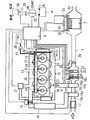
図1に例示するように、エンジンECU(5)と、DOC(2)を備え、
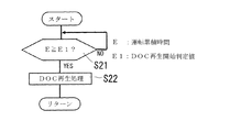
図2に例示するように、エンジンECU(5)の指令で、エンジン運転中、DOC再生処理(S22)がなされ、DOC再生処理(S22)では、DOC(2)に詰まった未燃焼堆積物が除去されるように構成された、ディーゼルエンジンにおいて、
図1に例示するように、DOC(2)の排気下流側に排気絞り弁(9a)を備え、図2に例示するDOC再生処理(S22)では、排気絞り弁(9a)の電動による開閉が繰り返されるように構成されている、ことを特徴とするディーゼルエンジン。
Invention specific matters of the invention according to
As illustrated in FIG. 1, an engine ECU (5) and a DOC (2) are provided.
As illustrated in FIG. 2, a DOC regeneration process (S22) is performed during engine operation in accordance with a command from the engine ECU (5). In the DOC regeneration process (S22), unburned deposits clogged in the DOC (2) are generated. In a diesel engine configured to be removed,
As illustrated in FIG. 1, an exhaust throttle valve (9a) is provided on the exhaust downstream side of the DOC (2). In the DOC regeneration process (S22) illustrated in FIG. 2, the exhaust throttle valve (9a) is electrically opened and closed. A diesel engine characterized by being configured to be repeated.
(請求項1に係る発明)
請求項1に係る発明は、次の効果を奏する。
《効果》 DOC再生処理での消費電力を小さくすることができる。
本発明では、図2に例示するように、DOC再生処理(S22)で、排気絞り弁(9a)の電動による開閉が繰り返されるように構成されているため、排気絞り弁(9a)の開閉によって発生した排気(9)の脈動で、DOC(2)に詰った未燃焼堆積物が吹き飛ばされる。また、排気絞り弁(9a)を閉弁した時に発生する排気(9)の圧縮熱で、DOC(2)に詰った未燃焼堆積物が燃焼する。この排気絞り弁(9a)の電動による開閉には、電気ヒータ(3)の発熱に比べ、大きな消費電力を必要とせず、DOC再生処理(S22)での消費電力を小さくすることができる。
(Invention of Claim 1)
The invention according to
<Effect> The power consumption in the DOC regeneration process can be reduced.
In the present invention, as illustrated in FIG. 2, in the DOC regeneration process (S22), the exhaust throttle valve (9a) is configured to be repeatedly opened and closed electrically. Therefore, the exhaust throttle valve (9a) is opened and closed. The pulsation of the generated exhaust (9) blows away the unburned deposits in the DOC (2). Further, the unburned deposits clogged in the DOC (2) are combusted by the compression heat of the exhaust (9) generated when the exhaust throttle valve (9a) is closed. The electric opening and closing of the exhaust throttle valve (9a) does not require a large amount of power consumption compared to the heat generated by the electric heater (3), and the power consumption in the DOC regeneration process (S22) can be reduced.
(請求項2に係る発明)
請求項2に係る発明は、請求項1に係る発明の効果に加え、次の効果を奏する。
《効果》 排気上流側DOCの早期再生を図ることができる。
本発明では、図5(B)(C)に例示するように、DOC(2)は、排気上流側DOC(2b)とその排気下流側に配置された排気下流側DOC(2c)で構成され、これらは、排気経路(1)の排気通過方向に貫通する多数のセルを備え、排気上流側DOC(2b)は排気下流側DOC(2c)よりも低いセル密度で構成されているため、排気上流側DOC(2b)には未燃焼堆積物が詰りにくく、詰っても、排気脈動で簡単に吹き飛ばされ、排気上流側DOC(2b)の早期再生を図ることができる。
(Invention of Claim 2)
The invention according to
<< Effect >> Early regeneration of the exhaust upstream DOC can be achieved.
In the present invention, as illustrated in FIGS. 5B and 5C, the DOC (2) is composed of an exhaust upstream DOC (2b) and an exhaust downstream DOC (2c) disposed on the exhaust downstream side. These include a large number of cells penetrating in the exhaust passage direction of the exhaust path (1), and the exhaust upstream DOC (2b) is configured with a lower cell density than the exhaust downstream DOC (2c). The upstream DOC (2b) is hard to be clogged with unburned deposits, and even if clogged, the exhaust pulsation is easily blown off, and the exhaust upstream DOC (2b) can be quickly regenerated.
(請求項3に係る発明)
請求項3に係る発明は、請求項1または請求項2に係る発明の効果に加え、次の効果を奏する。
《効果》 低負荷運転時のDPFの再生を促進することができる。
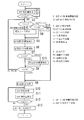
本発明では、図3に例示するように、DOC活性化処理で、排気絞り弁(9a)の開度が減少(S5)されるように構成されているため、DOC活性化処理で、図1に例示する排気絞り弁(9a)の排気上流側の排気圧力(P)が上昇し、排気(9)の昇温で、DOC(2)がスムーズに昇温され、排気(9)の温度が低い低負荷運転時でも、DOC(2)の活性化に時間がかからず、低負荷運転時のDPF(7)の再生を促進することができる。
(Invention of Claim 3)
The invention according to
<Effect> It is possible to promote regeneration of the DPF during low-load operation.
In the present invention, as illustrated in FIG. 3, the opening degree of the exhaust throttle valve (9a) is reduced (S5) in the DOC activation process. The exhaust pressure (P) on the exhaust upstream side of the exhaust throttle valve (9a) illustrated in Fig. 6 rises, the temperature of the exhaust (9) rises smoothly as the temperature of the exhaust (9) rises, and the temperature of the exhaust (9) Even during a low load operation, the activation of the DOC (2) does not take time, and the regeneration of the DPF (7) during the low load operation can be promoted.
(請求項4に係る発明)
請求項4に係る発明は、請求項3に係る発明の効果に加え、次の効果を奏する。
《効果》 DOC再生処理での背圧上昇による出力低下を防止することができる。
本発明では、図3に例示するように、DOC活性化処理で、排気絞り弁(9a)の排気上流側の排気圧力(P)が所定の過剰圧力領域(P3)に至った場合、その情報を検出したエンジンECU(5)の指令で、排気絞り弁(9a)の開度が増加(S15)されるように構成されているため、DOC再生処理での背圧上昇による出力低下を防止することができる。
(Invention of Claim 4)
The invention according to
<Effect> It is possible to prevent a decrease in output due to an increase in back pressure in the DOC regeneration process.
In the present invention, as illustrated in FIG. 3, in the DOC activation process, when the exhaust pressure (P) on the exhaust upstream side of the exhaust throttle valve (9a) reaches a predetermined excessive pressure region (P3), the information Since the opening degree of the exhaust throttle valve (9a) is increased (S15) in response to a command from the engine ECU (5) that detects this, an output decrease due to a back pressure increase in the DOC regeneration process is prevented. be able to.
(請求項5に係る発明)
請求項5に係る発明は、請求項3から請求項5のいずれかに係る発明の効果に加え、次の効果を奏する。
《効果》 DOC再生処理後の背圧上昇による出力低下を防止することができる。
本発明では、図3に例示するように、DOC活性化処理で、DOC(2)の推定温度(T)が活性化温度領域(T5)に至った場合には、その情報を検出したエンジンECU(5)の指令で、排気絞り弁(9a)が全開(S9)されるように構成されているため、DOC再生処理後の背圧上昇による出力低下を防止することができる。
(Invention according to claim 5)
The invention according to
<Effect> It is possible to prevent a decrease in output due to a back pressure increase after the DOC regeneration process.
In the present invention, as illustrated in FIG. 3, when the estimated temperature (T) of the DOC (2) reaches the activation temperature region (T5) in the DOC activation process, the engine ECU that has detected the information is detected. Since the exhaust throttle valve (9a) is configured to be fully opened (S9) by the command (5), it is possible to prevent a decrease in output due to a back pressure increase after the DOC regeneration process.
(請求項6に係る発明)
請求項6に係る発明は、請求項3から請求項5のいずれかに係る発明の効果に加え、次の効果を奏する。
《効果》 低負荷運転時のDPFの再生を促進することができる。
本発明では、図3,図4に例示するように、DOC活性化処理で、DOC(2)の推定温度(T)が活性化温度領域(T5)に至らない低温温度領域(T1)にある場合、その情報の検出に基づくエンジンECU(5)の指令で、電気ヒータ(3)の発熱(S4)がなされるように構成されているため、電気ヒータ(3)の発熱(S4)でDOC(2)の昇温が一層促進され、低負荷運転時のDPF(7)の再生を促進することができる。
(Invention of Claim 6)
The invention according to claim 6 has the following effects in addition to the effects of the invention according to any one of
<Effect> It is possible to promote regeneration of the DPF during low-load operation.
In the present invention, as illustrated in FIGS. 3 and 4, in the DOC activation process, the estimated temperature (T) of the DOC (2) is in the low temperature range (T1) that does not reach the activation temperature range (T5). In this case, since the heat generation (S4) of the electric heater (3) is generated by the command of the engine ECU (5) based on the detection of the information, the DOC is generated by the heat generation (S4) of the electric heater (3). The temperature increase in (2) is further promoted, and regeneration of the DPF (7) during low load operation can be promoted.
(請求項7に係る発明)
請求項7に係る発明は、請求項6に係る発明の効果に加え、次の効果を奏する。
《効果》 非効率な電気ヒータの発熱による電力消費を抑制することができる。
本発明では、図3,4に例示するように、DOC活性化処理で、DOC(2)の推定温度(T)が活性化温度領域(T5)未満で、低温度領域(T1)よりも高い中温度領域(T3)にある場合、その情報の検出に基づくエンジンECU(5)の指令で、電気ヒータ(3)の発熱(S4)が禁止されるように構成されているため、比較的温度が高く、加熱効率の低い中温度領域(T3)での非効率な電気ヒータ(3)の発熱(S4)による電力消費を抑制することができる。
(Invention of Claim 7)
The invention according to
<Effect> It is possible to suppress power consumption due to heat generated by the inefficient electric heater.
In the present invention, as illustrated in FIGS. 3 and 4, in the DOC activation process, the estimated temperature (T) of DOC (2) is lower than the activation temperature region (T5) and higher than the low temperature region (T1). When it is in the intermediate temperature region (T3), the engine ECU (5) based on the detection of the information is configured to prohibit the heat generation (S4) of the electric heater (3). The power consumption due to the heat generation (S4) of the inefficient electric heater (3) in the medium temperature region (T3) having a high heating efficiency and low heating efficiency can be suppressed.
(請求項8に係る発明)
請求項8に係る発明は、請求項6または請求項7に係る発明の効果に加え、次の効果を奏する。
《効果》 低負荷運転時のDPFの再生を促進することができる。
本発明では、図1に例示するように、電気ヒータ(3)は、DOC(2)のDOC入口(2a)に沿って配置されているため、電気ヒータ(3)からDOC(2)への熱の伝導ロスが小さく、DOC(2)の昇温効率が高まり、排気温度が低い低負荷運転時でも、DOC(2)の活性化に時間がかからず、低負荷運転時のDPF(7)の再生を促進することができる。
(Invention of Claim 8)
The invention according to
<Effect> It is possible to promote regeneration of the DPF during low-load operation.
In the present invention, as illustrated in FIG. 1, since the electric heater (3) is disposed along the DOC inlet (2a) of the DOC (2), the electric heater (3) is connected to the DOC (2). The heat conduction loss is small, the heating efficiency of the DOC (2) is increased, and even when the exhaust gas temperature is low, the activation of the DOC (2) does not take time, and the DPF (7 ) Can be promoted.
(請求項9に係る発明)
請求項9に係る発明は、請求項6から請求項8のいずれかに係る発明の効果に加え、次の効果を奏する。
《効果》 DPFの再生効率を高めることができる。
本発明では、図1に例示するように、DOC(2)の排気上流側にハニカム構造体(10)が設けられ、図5(A)に例示するように、ハニカム構造体(10)は、排気経路(1)の排気通過方向に貫通する多数のセル(10a)(10b)を備え、ハニカム構造体(10)のうち、中心ハニカム部(10d)のみが前記電気ヒータ(3)とされているため、排気経路(1)外への熱の逃げが起こり難い中心ハニカム部(10d)の電気ヒータ(3)で、排気(9)の温度が上昇され、排気(9)の昇温効率が高く、排気(9)の温度が低い低負荷運転時でも、速やかにDOC(2)が活性化され、DPF(7)の再生効率を高めることができる。
(Invention according to claim 9)
The invention according to
<Effect> The regeneration efficiency of the DPF can be increased.
In the present invention, as illustrated in FIG. 1, the honeycomb structure (10) is provided on the exhaust upstream side of the DOC (2). As illustrated in FIG. 5 (A), the honeycomb structure (10) A number of cells (10a) (10b) penetrating in the exhaust passage direction of the exhaust path (1) are provided, and only the central honeycomb portion (10d) of the honeycomb structure (10) is the electric heater (3). Therefore, the temperature of the exhaust (9) is increased by the electric heater (3) of the central honeycomb portion (10d) where heat escape to the outside of the exhaust path (1) is difficult to occur, and the temperature rise efficiency of the exhaust (9) is increased. Even during a low load operation where the temperature of the exhaust (9) is high and the temperature of the exhaust (9) is low, the DOC (2) is quickly activated, and the regeneration efficiency of the DPF (7) can be increased.
(請求項10に係る発明)
請求項10に係る発明は、請求項9に係る発明の効果に加え、次の効果を奏する。
《効果》 DPFの再生効率を高めることができる。
本発明では、図5(A)に例示するように電気ヒータ(3)を構成する中心ハニカム部(10d)は、その周囲を取り囲む周囲ハニカム部(10e)よりも高いセル密度で構成されているため、電気ヒータ(3)の放熱面積が広く、排気(9)の昇温効率が高まり、排気(9)の温度が低い低負荷運転時でも、速やかにDOC(2)が活性化され、DPF(7)の再生効率を高めることができる。
(Invention of Claim 10)
The invention according to
<Effect> The regeneration efficiency of the DPF can be increased.
In the present invention, as illustrated in FIG. 5A, the central honeycomb portion (10d) constituting the electric heater (3) has a higher cell density than the surrounding honeycomb portion (10e) surrounding the periphery. Therefore, the heat dissipation area of the electric heater (3) is wide, the temperature raising efficiency of the exhaust (9) is increased, and the DOC (2) is quickly activated even during low-load operation where the temperature of the exhaust (9) is low. The reproduction efficiency of (7) can be increased.
図1〜図5は本発明の実施形態に係るエンジンを説明する図であり、この実施形態では、立形の直列4気筒ディーゼルエンジンについて説明する。 FIGS. 1 to 5 are views for explaining an engine according to an embodiment of the present invention. In this embodiment, a vertical in-line four-cylinder diesel engine will be described.
エンジンの構成は、次の通りである。
図1に示すように、クランク軸(11)の架設方向を前後方向、フライホイール(12)の配置された側を後側、その反対側を前側、前後方向と直交するエンジン幅方向を横方向とする。
図1に示すように、このエンジンは、シリンダヘッド(13)の横一側に組みつけられた吸気マニホルド(14)と、シリンダヘッド(13)の横他側に組み付けられた排気マニホルド(15)を備えている。
図1に示すように、このエンジンは、エンジンECU(5)を備えている。
エンジンECUは、電子制御ユニットの略称で、エンジンECU(5)はマイコンである。
The configuration of the engine is as follows.
As shown in FIG. 1, the installation direction of the crankshaft (11) is the front-rear direction, the side on which the flywheel (12) is disposed is the rear side, the opposite side is the front side, and the engine width direction orthogonal to the front-rear direction is the lateral direction. And
As shown in FIG. 1, the engine includes an intake manifold (14) assembled on one side of the cylinder head (13) and an exhaust manifold (15) assembled on the other side of the cylinder head (13). It has.
As shown in FIG. 1, the engine includes an engine ECU (5).
The engine ECU is an abbreviation for an electronic control unit, and the engine ECU (5) is a microcomputer.
図1に示すように、このエンジンは、排気装置を備えている。
排気装置は、排気マニホルド(15)と、排気マニホルド(15)に設けられた過給機(16)の排気タービン(16a)と、排気タービン(16a)の排気出口(16b)から導出された排気導出通路(16c)を備えている。
As shown in FIG. 1, the engine includes an exhaust device.
The exhaust system includes an exhaust manifold (15), an exhaust turbine (16a) of a supercharger (16) provided in the exhaust manifold (15), and an exhaust derived from an exhaust outlet (16b) of the exhaust turbine (16a). A lead-out passage (16c) is provided.
図1に示すように、このエンジンは、吸気装置を備えている。
吸気装置は、過給機(16)のコンプレッサ(16d)と、コンプレッサ(16d)の吸気入口(16e)の吸気上流側に設けられたエアフローセンサ(17)と、コンプレッサ(16d)の過給気出口(16f)と吸気マニホルド(14)の間に配置されたインタークーラ(18)と、インタークーラ(18)と吸気マニホルド(14)の間に配置された吸気絞り弁(19)と、排気マニホルド(15)と吸気マニホルド(14)の間に配置されたEGRクーラ(20)と、EGRクーラ(20)と吸気マニホルド(14)の間に配置されたEGR弁(21)を備えている。EGRは、排気ガス還流の略称である。
吸気絞り弁(19)とEGR弁(21)は、いずれも電動式開閉弁で、これらはエンジンECU(5)を介して電源(4)に電気的に接続されている。エアフローセンサ(17)は吸気温度センサを備え、エンジンECU(5)に電気的に接続されている。電源(4)はバッテリである。
As shown in FIG. 1, this engine includes an intake device.
The intake device includes a compressor (16d) of the supercharger (16), an air flow sensor (17) provided on the intake upstream side of the intake inlet (16e) of the compressor (16d), and a supercharged air of the compressor (16d). An intercooler (18) disposed between the outlet (16f) and the intake manifold (14); an intake throttle valve (19) disposed between the intercooler (18) and the intake manifold (14); and an exhaust manifold EGR cooler (20) disposed between (15) and intake manifold (14), and EGR valve (21) disposed between EGR cooler (20) and intake manifold (14). EGR is an abbreviation for exhaust gas recirculation.
The intake throttle valve (19) and the EGR valve (21) are both electrically operated on / off valves, and these are electrically connected to the power source (4) via the engine ECU (5). The air flow sensor (17) includes an intake air temperature sensor and is electrically connected to the engine ECU (5). The power source (4) is a battery.
図1に示すように、このエンジンは、燃料噴射装置を備えている。
燃料噴射装置は、各燃焼室(23)に設けられた燃料噴射弁(24)と、燃料噴射弁(24)から噴射する燃料を蓄圧するコモンレール(25)と、コモンレール(25)に燃料タンク(26)から燃料を圧送する燃料サプライポンプ(27)を備えている。
燃料噴射弁(24)は電磁式開閉弁を備え、燃料サプライポンプ(27)は、電動式調圧弁を備え、これらはエンジンECU(5)を介して電源(4)に電気的に接続されている。
As shown in FIG. 1, the engine includes a fuel injection device.
The fuel injection device includes a fuel injection valve (24) provided in each combustion chamber (23), a common rail (25) for accumulating fuel injected from the fuel injection valve (24), and a fuel tank ( 26) a fuel supply pump (27) that pumps fuel from 26).
The fuel injection valve (24) includes an electromagnetic on-off valve, and the fuel supply pump (27) includes an electric pressure regulating valve, which are electrically connected to a power source (4) via an engine ECU (5). Yes.
図1に示すように、このエンジンは、調速装置を備えている。
調速装置は、エンジンの目標回転数を設定するアクセルレバー(28)の設定位置を検出するアクセルセンサ(29)と、エンジンの実回転数を検出する実回転数センサ(30)を備え、これらセンサ(29)(30)はエンジンECU(5)に電気的に接続されている。
As shown in FIG. 1, the engine includes a speed governor.
The speed governor includes an accelerator sensor (29) for detecting a set position of an accelerator lever (28) for setting a target engine speed, and an actual engine speed sensor (30) for detecting the actual engine speed. The sensors (29) and (30) are electrically connected to the engine ECU (5).
図1に示すように、このエンジンは、始動装置を備えている。
始動装置は、スタータモータ(31)と、キースイッチ(22)を備え、スタータモータ(31)とキースイッチ(22)は、エンジンECU(5)を介して電源(4)に電気的に接続されている。キースイッチ(22)は、OFF位置と、ON位置と、スタート位置を備えている。
As shown in FIG. 1, the engine includes a starting device.
The starting device includes a starter motor (31) and a key switch (22), and the starter motor (31) and the key switch (22) are electrically connected to a power source (4) via the engine ECU (5). ing. The key switch (22) has an OFF position, an ON position, and a start position.
エンジンECU(5)は、次のような運転制御を行うように構成されている。
エンジンの目標回転数と実回転数の回転数偏差を小さくするように、燃料噴射弁(24)からの燃料噴射量や噴射タイミングを設定し、負荷変動によるエンジンの回転数変動を小さくする。
エンジンの回転数と負荷と吸気量と吸気温度に応じ、吸気絞り弁(19)とEGR弁(21)の開度を調節し、吸気量やEGR率を調節する。
キースイッチ(22)がスタート位置に投入されると、スタータモータ(31)を駆動し、エンジンの始動を行う。キースイッチ(22)がON位置に投入されると、電源(8)からエンジン各部への通電により、エンジン運転状態が維持され、キースイッチ(22)がOFF位置に投入されると、燃料噴射弁(24)からの燃料噴射が停止され、エンジンが停止される。
The engine ECU (5) is configured to perform the following operation control.
The fuel injection amount and the injection timing from the fuel injection valve (24) are set so as to reduce the rotational speed deviation between the target engine speed and the actual engine speed, and the engine speed fluctuation due to load fluctuation is reduced.
In accordance with the engine speed, load, intake air amount, and intake air temperature, the opening degree of the intake throttle valve (19) and the EGR valve (21) is adjusted to adjust the intake air amount and the EGR rate.
When the key switch (22) is turned to the start position, the starter motor (31) is driven to start the engine. When the key switch (22) is turned on, the engine operating state is maintained by energizing each part of the engine from the power supply (8). When the key switch (22) is turned on, the fuel injection valve The fuel injection from (24) is stopped and the engine is stopped.
図1に示すように、この排気処理装置は、エンジンECU(5)と、DOC(2)を備え、図2に示すように、エンジンECU(5)の指令で、エンジン運転中、DOC再生処理(S22)がなされ、DOC再生処理(S22)では、DOC(2)に詰まった未燃焼堆積物が除去されるように構成されている。
このため、この排気処理装置では、DOC再生処理によりDOCの機能を回復することができる。
As shown in FIG. 1, this exhaust treatment apparatus includes an engine ECU (5) and a DOC (2). As shown in FIG. 2, a DOC regeneration process is performed during engine operation in accordance with a command from the engine ECU (5). (S22) is performed, and in the DOC regeneration process (S22), unburned deposits clogged in the DOC (2) are removed.
For this reason, in this exhaust treatment apparatus, the function of the DOC can be recovered by the DOC regeneration process.
図1に示すように、この排気処理装置は、DOC(2)の排気下流側に排気絞り弁(9a)を備え、図2に示すように、DOC再生処理(S22)では、排気絞り弁(9a)の電動による開閉が繰り返されるように構成されている。
このため、この排気処理装置では、排気絞り弁(9a)の開閉によって発生した排気(9)の脈動で、DOC(2)に詰った未燃焼堆積物が吹き飛ばされる。また、排気絞り弁(9a)を閉弁した時に発生する排気(9)の圧縮熱で、DOC(2)に詰った未燃焼堆積物が燃焼する。この排気絞り弁(9a)の電動による開閉には、電気ヒータ(3)の発熱に比べ、大きな消費電力を必要とせず、DOC再生処理(S22)での消費電力を小さくすることができる。
As shown in FIG. 1, this exhaust treatment device includes an exhaust throttle valve (9a) on the exhaust downstream side of the DOC (2). As shown in FIG. 2, in the DOC regeneration process (S22), an exhaust throttle valve ( 9a) is configured to be repeatedly opened and closed by electric drive.
For this reason, in this exhaust treatment device, unburned deposits clogged in the DOC (2) are blown away by the pulsation of the exhaust (9) generated by opening and closing the exhaust throttle valve (9a). Further, the unburned deposits clogged in the DOC (2) are combusted by the compression heat of the exhaust (9) generated when the exhaust throttle valve (9a) is closed. The electric opening and closing of the exhaust throttle valve (9a) does not require a large amount of power consumption compared to the heat generated by the electric heater (3), and the power consumption in the DOC regeneration process (S22) can be reduced.
図1,図5(B)(C)に示すように、この排気処理装置では、DOC(2)は、排気上流側DOC(2b)とその排気下流側に配置された排気下流側DOC(2c)で構成され、これらは、排気経路(1)の排気通過方向に貫通する多数のセル(2e)(2f)を備え、排気上流側DOC(2b)は排気下流側DOC(2c)よりも低いセル密度で構成されている。
このため、この排気処理装置では、排気上流側DOC(2b)には未燃焼堆積物が詰りにくく、詰っても、排気脈動で簡単に吹き飛ばされ、排気上流側DOC(2b)の早期再生を図ることができる。
As shown in FIGS. 1, 5B, and 5C, in this exhaust treatment apparatus, the DOC (2) includes an exhaust upstream DOC (2b) and an exhaust downstream DOC (2c) arranged on the exhaust downstream side. These are provided with a number of cells (2e) (2f) penetrating in the exhaust passage direction of the exhaust path (1), and the exhaust upstream DOC (2b) is lower than the exhaust downstream DOC (2c) It is composed of cell density.
For this reason, in this exhaust treatment device, unburned deposits are not easily clogged in the exhaust upstream DOC (2b), and even if clogged, the exhaust pulsation is easily blown away, and the exhaust upstream DOC (2b) is quickly regenerated. be able to.
この排気処理装置では、排気上流側DOC(2b)は、排気下流側DOC(2c)よりも低いセル密度で構成され、熱容量も小さくなるように構成されているため、排気上流側DOC(2b)の活性化に要する時間が短縮され、低負荷運転時のDPFの再生を促進することができる。 In this exhaust treatment device, the exhaust upstream DOC (2b) is configured to have a lower cell density and a smaller heat capacity than the exhaust downstream DOC (2c), so that the exhaust upstream DOC (2b) Time required for activation of the DPF can be shortened, and regeneration of the DPF during low-load operation can be promoted.
図2に示すエンジンECU(5)によるDOC再生処理の流れは次の通りである。
ステップ(S21)では、前回のDOC再生が終了してからの運転累積時間Eが、所定のDOC再生開始判定値E1に達したか否かが判定され、判定が肯定されるまでステップ(S21)が繰り返され、判定が否定された場合には、ステップ(S22)でDOC再生処理がなされる。
The flow of the DOC regeneration process by the engine ECU (5) shown in FIG. 2 is as follows.
In step (S21), it is determined whether or not the accumulated operation time E after the end of the previous DOC regeneration has reached a predetermined DOC regeneration start determination value E1, and step (S21) until the determination is affirmed. Is repeated and if the determination is negative, a DOC regeneration process is performed in step (S22).
図1に示すように、この排気処理装置は、DOC(2)の排気下流側に配置されたDPF(7)と、DOC(2)の排気上流側に配置された燃料供給装置(8)を備えている。
図3に示すように、この排気処理装置では、DPF(7)のPM堆積量推定値(F)が所定のDPF再生開始判定値(FS)に至っているが、DOC(2)の推定温度(T)が活性化温度領域(T5)に至っていない場合、その情報を検出したエンジンECU(5)の指令で、DOC活性化処理がなされ、DOC活性化処理では、排気(9)が昇温され、DOC(2)の推定温度(T)が活性化温度領域(T5)に至った場合、その情報を検出したエンジンECU(5)の指令で、DPF再生処理(S10)がなされ、DPF再生処理(S10)では、図1に示す燃料供給装置(8)から排気(9)に燃料が供給され、この燃料(9)のDOC(2)での触媒燃焼で、排気(9)が昇温され、この排気(9)の熱で、DPF(7)に堆積したPMが焼却されるように構成されている。
このため、この排気処理装置では、排気(9)の温度が低い場合でも、DOC活性化処理で、DPF(7)の再生が可能となる。
As shown in FIG. 1, this exhaust treatment device includes a DPF (7) disposed on the exhaust downstream side of the DOC (2) and a fuel supply device (8) disposed on the exhaust upstream side of the DOC (2). I have.
As shown in FIG. 3, in this exhaust treatment apparatus, the PM accumulation amount estimated value (F) of the DPF (7) reaches the predetermined DPF regeneration start determination value (FS), but the estimated temperature of the DOC (2) ( When T) does not reach the activation temperature region (T5), the DOC activation process is performed according to the command of the engine ECU (5) that has detected the information. In the DOC activation process, the exhaust (9) is heated. When the estimated temperature (T) of the DOC (2) reaches the activation temperature region (T5), the DPF regeneration process (S10) is performed by the command of the engine ECU (5) that has detected the information, and the DPF regeneration process In (S10), fuel is supplied from the fuel supply device (8) shown in FIG. 1 to the exhaust (9), and the temperature of the exhaust (9) is raised by catalytic combustion of the fuel (9) at the DOC (2). The PM accumulated in the DPF (7) is incinerated by the heat of the exhaust (9).
For this reason, in this exhaust treatment apparatus, even when the temperature of the exhaust (9) is low, the DPF (7) can be regenerated by the DOC activation treatment.
この排気処理装置では、図3に示すように、DOC活性化処理では、排気絞り弁(9a)の開度が減少(S5)されるように構成されている。
このため、この排気処理装置では、DOC活性化処理で、図1に例示する排気絞り弁(9a)の排気上流側の排気圧力(P)が上昇し、排気(9)の昇温で、DOC(2)がスムーズに昇温され、排気(9)の温度が低い低負荷運転時でも、DOC(2)の活性化に時間がかからず、低負荷運転時のDPF(7)の再生を促進することができる。図1に示すように、排気絞り弁(9a)はバタフライ型の電動式開閉弁で、これはエンジンECU(5)を介して電源(4)に電気的に接続されている。
As shown in FIG. 3, the exhaust processing apparatus is configured such that the opening of the exhaust throttle valve (9a) is decreased (S5) in the DOC activation processing.
For this reason, in this exhaust treatment apparatus, the exhaust pressure (P) on the exhaust upstream side of the exhaust throttle valve (9a) illustrated in FIG. 1 is increased by the DOC activation process, and the DOC is increased by raising the temperature of the exhaust (9). Even when the temperature of (2) is smoothly raised and the exhaust (9) temperature is low and the load is low, activation of the DOC (2) does not take time, and the DPF (7) is regenerated during the low load. Can be promoted. As shown in FIG. 1, the exhaust throttle valve (9a) is a butterfly type electric on-off valve, which is electrically connected to a power source (4) via an engine ECU (5).
DOCは、ディーゼル酸化触媒の略称である。
図1に示すように、DOC(2)を構成する排気上流側DOC(2b)と排気下流側DOC(2c)は、いずれも酸化触媒成分を担持する担体を備えている。
担体は、内部に軸長方向に沿う多数のセルが貫通状に並設されたフロースルー型のメタルハニカムであり、セル内に白金やパラジウムやロジウム等の酸化触媒成分が担持されている。
DOC is an abbreviation for diesel oxidation catalyst.
As shown in FIG. 1, both the exhaust upstream DOC (2b) and the exhaust downstream DOC (2c) constituting the DOC (2) include a carrier carrying an oxidation catalyst component.
The support is a flow-through type metal honeycomb in which a large number of cells along the axial length direction are arranged in a penetrating manner inside, and an oxidation catalyst component such as platinum, palladium, and rhodium is supported in the cell.
DPFは、ディーゼル・パティキュレート・フィルタの略称であり、DPF(7)は、排気(9)に含まれるPMを捕捉する。PMは、粒子状物質の略称である。
DPF(7)は、内部に軸長方向に沿う多数のセルが並設され、隣り合うセルの入口と出口が交互に目封じされたウォールフローハニカム型のセラミックハニカムである。
DPF is an abbreviation for diesel particulate filter, and DPF (7) captures PM contained in exhaust (9). PM is an abbreviation for particulate matter.
The DPF (7) is a wall flow honeycomb type ceramic honeycomb in which a large number of cells along the axial length direction are arranged in parallel and the inlets and outlets of adjacent cells are alternately sealed.
図1に示すように、DOC(2)とDPF(7)は、排気経路(1)に配置されている。
排気経路(1)は、排気タービン(16a)の排気出口(16b)から導出された排気導出通路(16c)の下流に配置され、途中にDOC収容ケース(1a)と、その排気下流側に配置されたDPF収容ケース(1b)を備え、DOC収容ケース(1a)に電気ヒータ(3)とDOC(2)が収容され、DPF収容ケース(1b)にDPF(7)が収容されている。
As shown in FIG. 1, the DOC (2) and the DPF (7) are disposed in the exhaust path (1).
The exhaust passage (1) is arranged downstream of the exhaust outlet passage (16c) led out from the exhaust outlet (16b) of the exhaust turbine (16a), and is arranged in the middle of the DOC storage case (1a) and the exhaust downstream side thereof. The DPF storage case (1b) is provided, the electric heater (3) and the DOC (2) are stored in the DOC storage case (1a), and the DPF (7) is stored in the DPF storage case (1b).
DPF(7)のPM堆積量の推定は、次のようにして行われる。
図1に示すように、排気処理装置は、DPF(7)の出入口の差圧を検出する差圧センサ(32)を備え、差圧センサ(32)はエンジンECU(5)に電気的に接続され、DPF(7)の出入口の差圧に基づいて、エンジンECU(5)がDPF(7)に堆積したPMの堆積量の推定値を演算する。
The estimation of the PM deposition amount of the DPF (7) is performed as follows.
As shown in FIG. 1, the exhaust treatment device includes a differential pressure sensor (32) that detects a differential pressure at the inlet / outlet of the DPF (7), and the differential pressure sensor (32) is electrically connected to the engine ECU (5). Then, based on the differential pressure at the inlet / outlet of the DPF (7), the engine ECU (5) calculates an estimated value of the amount of PM deposited on the DPF (7).
DOC(2)の温度推定は、次のようにして行われる。
図1に示すように、排気処理装置は、排気上流側DOC(2b)の入口と出口のDOC入口側排気温度センサ(34)とDOC出口側排気温度センサ(35)と、排気下流側DOC(2c)の出口のDOC出口側排気温度センサ(39)を備え、これらセンサ(34)(35)(39)はエンジンECU(5)に電気的に接続されている。エンジンECU(5)では、これらセンサ(34)(35)(39)からの排気温度の情報に基づいて、排気上流側DOC(2b)と排気下流側DOC(2c)の推定温度を演算する。
The temperature estimation of DOC (2) is performed as follows.
As shown in FIG. 1, the exhaust treatment apparatus includes an exhaust upstream DOC (2b) inlet and outlet DOC inlet side exhaust temperature sensor (34), a DOC outlet side exhaust temperature sensor (35), an exhaust downstream side DOC ( 2c) is provided with a DOC outlet side exhaust temperature sensor (39), and these sensors (34), (35), and (39) are electrically connected to the engine ECU (5). The engine ECU (5) calculates the estimated temperatures of the exhaust upstream DOC (2b) and the exhaust downstream DOC (2c) based on the exhaust temperature information from the sensors (34) (35) (39).
燃料供給装置(8)には、コモンレール式の燃料噴射装置が用いられ、DPF再生処理では、燃料噴射弁(24)からポスト噴射がなされ、燃料が排気(9)に混入され、この燃料のDOC(2)での触媒燃焼で、排気(9)が昇温され、この排気(9)の熱で、DPF(7)に堆積したPMが焼却される。
ポスト噴射とは、燃焼サイクル中、燃料噴射弁(24)からメイン噴射後、膨張行程または排気行程で燃焼室(23)に行われる燃料噴射である。
DPF再生処理では、DPF(7)の入口排気温度が所定の再生可能温度を維持するよう、ポスト噴射量が調節される。
DPF再生処理では、ポスト噴射に代え、排気管に設けた燃料噴射弁から排気に燃料を噴射する排気管噴射を行ってもよい。
As the fuel supply device (8), a common rail type fuel injection device is used. In the DPF regeneration process, post-injection is performed from the fuel injection valve (24), and fuel is mixed into the exhaust (9). Due to the catalytic combustion in (2), the temperature of the exhaust (9) is raised, and the PM deposited on the DPF (7) is incinerated by the heat of the exhaust (9).
Post-injection is fuel injection performed in the combustion chamber (23) in the expansion stroke or exhaust stroke after the main injection from the fuel injection valve (24) during the combustion cycle.
In the DPF regeneration process, the post injection amount is adjusted so that the inlet exhaust temperature of the DPF (7) maintains a predetermined reproducible temperature.
In the DPF regeneration process, exhaust pipe injection for injecting fuel into the exhaust from a fuel injection valve provided in the exhaust pipe may be performed instead of post injection.
DPF(7)に堆積するPM堆積量推定値がDPF(7)の再生終了判定値(FF)を下回った場合、その検出に基づくエンジンECU(5)の指令により、DPF再生処理は終了する。
DPF再生処理は、DPF(7)の再生処理が開始された後、DPF(7)の入口排気温度が所定の再生可能温度を維持した時間が所定の再生終了判定値に至った場合に終了させてもよい。DPF(7)の入口排気温度は、DPF入口側排気温度センサ(38)で検出することができる。
なお、排気処理装置は、DPF(7)の出口側排気温度センサ(33)を備え、DPF(7)の排気側出口温度が所定の異常燃焼基準値を越えた場合、その検出に基づくエンジンECU(5)の指令により、DPF再生処理を緊急終了させる。
When the estimated PM accumulation amount accumulated in the DPF (7) falls below the regeneration end determination value (FF) of the DPF (7), the DPF regeneration process is terminated by an instruction of the engine ECU (5) based on the detection.
The DPF regeneration process is terminated when the time during which the inlet exhaust temperature of the DPF (7) maintains a predetermined regeneration possible temperature reaches a predetermined regeneration end determination value after the regeneration process of the DPF (7) is started. May be. The inlet exhaust temperature of the DPF (7) can be detected by the DPF inlet side exhaust temperature sensor (38).
The exhaust treatment device includes an outlet side exhaust temperature sensor (33) of the DPF (7). When the exhaust side outlet temperature of the DPF (7) exceeds a predetermined abnormal combustion reference value, the engine ECU based on the detection The DPF regeneration process is terminated urgently by the command (5).
図3に示すように、この排気処理装置では、DOC活性化処理で、排気絞り弁(9a)の排気上流側の排気圧力(P)が所定の過剰圧力領域(P3)に至った場合、その情報を検出したエンジンECU(5)の指令で、排気絞り弁(9a)の開度が増加(S15)されるように構成されているため、DOC再生処理での背圧上昇による出力低下を防止することができる。
排気絞り弁(9a)の排気上流側の排気圧力(P)は、エアフローセンサ(17)での吸気量の検出値とDOC出口側排気温度から排気圧力を算出するマップに基づいて、エンジンECU(5)が推定値を演算する。
As shown in FIG. 3, in this exhaust treatment device, when the exhaust pressure (P) on the exhaust upstream side of the exhaust throttle valve (9a) reaches a predetermined excessive pressure region (P3) in the DOC activation process, Since the opening degree of the exhaust throttle valve (9a) is increased (S15) in response to a command from the engine ECU (5) that has detected the information, output reduction due to increased back pressure in the DOC regeneration process is prevented. can do.
The exhaust pressure (P) on the exhaust upstream side of the exhaust throttle valve (9a) is calculated based on a map for calculating the exhaust pressure from the detected value of the intake air amount by the air flow sensor (17) and the exhaust temperature on the DOC outlet side. 5) computes the estimated value.
図3に示すように、この排気処理装置では、DOC活性化処理で、排気上流側DOC(2b)の推定温度(T)が活性化温度領域(T5)に至った場合には、その情報を検出したエンジンECU(5)の指令で、排気絞り弁(9a)が全開(S9)されるように構成されているため、DOC活性化処理での背圧上昇による出力低下を防止することができる。。 As shown in FIG. 3, in this exhaust treatment apparatus, when the estimated temperature (T) of the exhaust upstream DOC (2b) reaches the activation temperature region (T5) in the DOC activation process, the information is displayed. Since the exhaust throttle valve (9a) is configured to be fully opened (S9) according to the detected command from the engine ECU (5), it is possible to prevent a decrease in output due to a back pressure increase in the DOC activation process. . .
図1に示すように、この排気処理装置では、DOC(2)の排気上流側に電気ヒータ(3)が設けられ、図3,図3に示すように、DOC活性化処理で、DOC(2)の推定温度(T)が活性化温度領域(T5)に至らない低温度領域(T1)にある場合、その情報の検出に基づくエンジンECU(5)の指令で、電気ヒータ(3)が発熱(S4)するように構成されている。
このため、この排気処理装置では、電気ヒータ(3)の発熱(S4)で、DOC(2)の昇温が一層促進され、低負荷運転時のDPF(7)の再生を促進することができる。
As shown in FIG. 1, in this exhaust treatment apparatus, an electric heater (3) is provided on the exhaust upstream side of the DOC (2). As shown in FIGS. 3 and 3, DOC (2 ) In the low temperature region (T1) that does not reach the activation temperature region (T5), the electric heater (3) generates heat in response to a command from the engine ECU (5) based on the detection of the information. (S4) is configured.
For this reason, in this exhaust treatment device, the temperature rise of the DOC (2) is further promoted by the heat generation (S4) of the electric heater (3), and the regeneration of the DPF (7) during the low load operation can be promoted. .
図3,図4に示すように、この排気処理装置では、DOC活性化処理で、DOC(2)の推定温度(T)が活性化温度領域(T5)未満で、低温度領域(T1)よりも高い中温度領域(T3)にある場合、その情報の検出に基づくエンジンECU(5)の指令で、電気ヒータ(3)の発熱(S4)が禁止されるように構成されている。
このため、この排気処理装置では、比較的温度が高く、加熱効率の低い中温度領域(T3)での非効率な電気ヒータ(3)の発熱(S4)による電力消費を抑制することができる。
As shown in FIGS. 3 and 4, in this exhaust treatment apparatus, the estimated temperature (T) of the DOC (2) is lower than the activation temperature region (T5) and lower than the low temperature region (T1). When the temperature is in the high intermediate temperature range (T3), the heat generation (S4) of the electric heater (3) is prohibited by the command of the engine ECU (5) based on the detection of the information.
For this reason, in this exhaust treatment apparatus, it is possible to suppress power consumption due to heat generation (S4) of the inefficient electric heater (3) in the intermediate temperature region (T3) where the temperature is relatively high and the heating efficiency is low.
図1に示すように、この排気処理装置では、電気ヒータ(3)は、DOC(2)のDOC入口(2a)に沿って配置されているため、電気ヒータ(3)からDOC(2)への熱の伝導ロスが小さく、DOC(2)の昇温効率が高まり、排気温度が低い低負荷運転時でも、DOC(2)の活性化に時間がかからず、DPF(7)の再生を促進することができる。 As shown in FIG. 1, in this exhaust treatment apparatus, since the electric heater (3) is disposed along the DOC inlet (2a) of the DOC (2), the electric heater (3) is moved to the DOC (2). The heat conduction loss of DOC (2) is small, the heating efficiency of DOC (2) is increased, and even during low load operation where the exhaust temperature is low, the activation of DOC (2) does not take time, and the regeneration of DPF (7) Can be promoted.
図1に示すように、この排気処理装置では、DOC(2)の排気上流側にハニカム構造体(10)が設けられ、図4(A)に示すように、ハニカム構造体(10)は、排気経路(1)の排気通過方向に貫通する多数のセル(10a)(10b)を備え、ハニカム構造体(10)のうち、中心ハニカム部(10d)のみが前記電気ヒータ(3)とされている。
このため、この排気処理装置では、排気経路(1)外への熱の逃げが起こり難い中心ハニカム部(10d)の電気ヒータ(3)で、排気(9)の温度が上昇され、排気(9)の昇温効率が高く、排気(9)の温度が低い低負荷運転時でも、速やかにDOC(2)が活性化され、DPF(7)の再生効率を高めることができる。電気ヒータ(3)を周囲から取り囲む周囲ハニカム部(10e)は、絶縁体(10f)を介して電気ヒータ(3)と電気的に絶縁されている。
As shown in FIG. 1, in this exhaust treatment apparatus, a honeycomb structure (10) is provided on the exhaust upstream side of the DOC (2). As shown in FIG. 4 (A), the honeycomb structure (10) A number of cells (10a) (10b) penetrating in the exhaust passage direction of the exhaust path (1) are provided, and only the central honeycomb portion (10d) of the honeycomb structure (10) is the electric heater (3). Yes.
For this reason, in this exhaust treatment device, the temperature of the exhaust (9) is increased by the electric heater (3) of the central honeycomb portion (10d) where heat escape to the outside of the exhaust path (1) hardly occurs, and the exhaust (9 ) Is high and the DOC (2) is quickly activated even during low-load operation where the temperature of the exhaust (9) is low, and the regeneration efficiency of the DPF (7) can be increased. The surrounding honeycomb portion (10e) surrounding the electric heater (3) from the periphery is electrically insulated from the electric heater (3) through an insulator (10f).
図4(A)に示すように、この排気処理装置では、電気ヒータ(3)を構成する中心ハニカム部(10d)は、その周囲を取り囲む周囲ハニカム部(10e)よりも高いセル密度で構成されている。
このため、この排気処理装置では、電気ヒータ(3)の放熱面積が広く、排気(9)の昇温効率が高く、排気(9)の温度が低い低負荷運転時でも、速やかに、排気上流側DOC(2b)が活性化され、DPF(7)の再生効率を高めることができる。
セル密度は、ハニカムの中心軸線(10c)と直交する面の単位面積当たりのセルの数で示され、数値が大きい程、セル密度は高くなる。
As shown in FIG. 4A, in this exhaust treatment apparatus, the central honeycomb portion (10d) constituting the electric heater (3) is configured with a higher cell density than the surrounding honeycomb portion (10e) surrounding the periphery. ing.
For this reason, in this exhaust treatment device, the heat dissipation area of the electric heater (3) is wide, the temperature raising efficiency of the exhaust (9) is high, and the exhaust (9) temperature is low. The side DOC (2b) is activated, and the regeneration efficiency of the DPF (7) can be increased.
The cell density is indicated by the number of cells per unit area of the plane orthogonal to the central axis (10c) of the honeycomb. The larger the numerical value, the higher the cell density.
図4(A)(B)に示すハニカム構造体(10)と排気上流側DOC(2b)の関係は、次の通りである。
図4(A)に示すハニカム構造体(10)は、電気ヒータ(3)となる中心ハニカム部(10d)と、電気ヒータ(3)を周囲から取り囲む周囲ハニカム部(10e)のいずれも、内部に軸長方向に沿う多数のセル(10a)(10b)が貫通状に並設されたフロースルー型のメタルハニカムである。ハニカム構造体(10)と排気上流側DOC(2b)はいずれも円筒径で同じ外径寸法となっており、ハニカム構造体(10)の中心軸線(10c)と、排気上流側DOC(2b)の中心軸線(2d)は同一の直線状に位置し、ハニカム構造体(10)の電気ヒータ(3)は、排気上流側DOC(2b)の中心部(36)と対向し、ハニカム構造体(10)の周囲ハニカム部(10e)は、排気上流側DOC(2b)の中心部(36)を取り囲む周囲部(37)と対向している。ハニカム構造体(10)の周囲ハニカム部(10e)と排気上流側DOC(2b)のセル密度は同じに設定されている。
The relationship between the honeycomb structure (10) shown in FIGS. 4A and 4B and the exhaust upstream DOC (2b) is as follows.
The honeycomb structure (10) shown in FIG. 4 (A) includes both a central honeycomb portion (10d) serving as an electric heater (3) and a peripheral honeycomb portion (10e) surrounding the electric heater (3) from the inside. A flow-through type metal honeycomb in which a large number of cells (10a) and (10b) along the axial direction are arranged side by side. The honeycomb structure (10) and the exhaust upstream DOC (2b) are both cylindrical and have the same outer diameter, and the central axis (10c) of the honeycomb structure (10) and the exhaust upstream DOC (2b) The central axis (2d) of the honeycomb structure (10) is positioned in the same straight line, and the electric heater (3) of the honeycomb structure (10) faces the center (36) of the exhaust upstream DOC (2b), and the honeycomb structure ( The peripheral honeycomb portion (10e) of 10) faces the peripheral portion (37) surrounding the central portion (36) of the exhaust upstream DOC (2b). The cell densities of the surrounding honeycomb portion (10e) of the honeycomb structure (10) and the exhaust upstream DOC (2b) are set to be the same.
図5(B)(C)に示す排気上流側DOC(2b)と排気下流側DOC(2b)の関係は、次の通りである。
図5(B)(C)に示す排気上流側DOC(2b)と排気下流側DOC(2c)はいずれも円筒径で同じ外径寸法となっており、排気上流側DOC(2b)の中心軸線(2d)と、排気下流側DOC(2c)の中心軸線(2g)は同一の直線状に位置し、排気上流側DOC(2b)の中心部(36)は排気下流側DOC(2c)の中心部(40)と対向し、排気上流側DOC(2b)の周囲ハニカム部(37)は、排気下流側DOC(2c)の中心部(40)を取り囲む周囲部(41)と対向している。
The relationship between the exhaust upstream DOC (2b) and the exhaust downstream DOC (2b) shown in FIGS. 5B and 5C is as follows.
The exhaust upstream DOC (2b) and the exhaust downstream DOC (2c) shown in FIGS. 5B and 5C are both cylindrical and have the same outer diameter, and the central axis of the exhaust upstream DOC (2b) (2d) and the central axis (2g) of the exhaust downstream DOC (2c) are located on the same straight line, and the central portion (36) of the exhaust upstream DOC (2b) is the center of the exhaust downstream DOC (2c). The peripheral honeycomb part (37) of the exhaust upstream DOC (2b) faces the peripheral part (41) surrounding the central part (40) of the exhaust downstream DOC (2c).
図3に示すエンジンECU(5)によるDOC活性化処理とDPF再生処理の流れは、次の通りである。
ステップ(S1)では、DPF(7)のPM堆積量の推定が行われ、ステップ(S2)に進む。
ステップ(S2)では、DPF(7)のPM堆積量推定値(F)がDPF再生開始の判定値(FS)以上であるか否かが判定され、判定が肯定されるまで、ステップ(S1)とステップ(S2)が繰り返され、ステップ(S2)での判定が肯定されると、ステップ(S3)に進む。
ステップ(S3)では、DOC(2)の推定温度(T)が、活性化判定値(T4)未満の中温度判定値(T2)以上か否かが判定され、判定が否定された場合、すなわち、DOC(2)の推定温度(T)が低温度領域(T1)にある場合、ステップ(S4)に進み、DOC活性化処理がなされる。
The flow of the DOC activation process and the DPF regeneration process by the engine ECU (5) shown in FIG. 3 is as follows.
In step (S1), the PM accumulation amount of the DPF (7) is estimated, and the process proceeds to step (S2).
In step (S2), it is determined whether or not the PM accumulation amount estimated value (F) of the DPF (7) is greater than or equal to the determination value (FS) for starting DPF regeneration, and step (S1) is continued until the determination is affirmed. Step (S2) is repeated, and if the determination in step (S2) is affirmed, the process proceeds to step (S3).
In step (S3), it is determined whether or not the estimated temperature (T) of DOC (2) is equal to or higher than the intermediate temperature determination value (T2) less than the activation determination value (T4). When the estimated temperature (T) of DOC (2) is in the low temperature region (T1), the process proceeds to step (S4), and the DOC activation process is performed.
ステップ(S4)では、電気ヒータ(3)が発熱され、ステップ(S5)に進む。ス
ステップ(S5)では、排気絞り弁(9a)の開度が減少され、ステップ(S6)に進む。
ステップ(S6)では、吸気絞り弁(19)の開度が増加され、吸気量が増加し、排気量の増加で、排気圧力(P)が増加し、排気(9)の昇温が促進され、ステップ(S7)に進む。
ステップ(S7)では、DOC(2)の排気上流側の排気圧力(P)が過剰判定値(P2)以上か否かが判定され、判定が否定された場合、すなわち、排気圧力(P)が許容圧力領域(P1)にある場合、ステップ(S8)に進む。
ステップ(S8)では、DOC(2)の推定温度(T)が活性化判定値(T4)以上か否かが判定され、判定が肯定の場合、すなわち排気上流側DOC(2b)の推定温度(T)が活性化温度領域(T5)に至っている場合には、DOC活性化処理を終了し、ステップ(S9)に進む。
In step (S4), the electric heater (3) generates heat, and the process proceeds to step (S5). In step (S5), the opening degree of the exhaust throttle valve (9a) is decreased, and the process proceeds to step (S6).
In step (S6), the opening degree of the intake throttle valve (19) is increased, the intake amount is increased, the exhaust amount is increased, the exhaust pressure (P) is increased, and the temperature rise of the exhaust (9) is promoted. The process proceeds to step (S7).
In step (S7), it is determined whether or not the exhaust pressure (P) on the exhaust upstream side of the DOC (2) is equal to or higher than the excess determination value (P2). If the determination is negative, that is, the exhaust pressure (P) is If it is in the allowable pressure region (P1), the process proceeds to step (S8).
In step (S8), it is determined whether or not the estimated temperature (T) of DOC (2) is equal to or higher than the activation determination value (T4). If the determination is affirmative, that is, the estimated temperature of exhaust upstream DOC (2b) ( If T) has reached the activation temperature region (T5), the DOC activation process is terminated, and the process proceeds to step (S9).
ステップ(S9)では、排気絞り弁(9a)が全開され、ステップ(S10)に進む。
ステップ(S10)では、DPF再生処理がなされ、ステップ(S11)に進む。
ステップ(S11)では、DPF(7)のPM堆積量の推定が行われ、ステップ(S12)に進む。
ステップ(S12)では、DPF(7)のPM堆積量推定値(F)がDPF再生終了判定値(FF)以下であるか否かが判定され、判定が肯定された場合、すなわち、DPF再生終了判定がなされた場合、ステップ(S13)に進む。ステップ(S13)では、DPF再生処理が終了され、ステップ(S1)に戻る。
In step (S9), the exhaust throttle valve (9a) is fully opened, and the process proceeds to step (S10).
In step (S10), DPF regeneration processing is performed, and the process proceeds to step (S11).
In step (S11), the PM accumulation amount of the DPF (7) is estimated, and the process proceeds to step (S12).
In step (S12), it is determined whether or not the PM accumulation amount estimated value (F) of the DPF (7) is equal to or less than the DPF regeneration end determination value (FF). If the determination is affirmative, that is, the DPF regeneration end When the determination is made, the process proceeds to step (S13). In step (S13), the DPF regeneration process is terminated, and the process returns to step (S1).
ステップ(S3)で、判定が否定された場合、すなわち、排気上流側DOC(2b)の推定温度(T)が中温度領域(T3)または活性化温度領域(T5)に至っている場合、ステップ(S14)に進む。
ステップ(S14)では、排気上流側DOC(2b)の推定温度(T)が活性化判定値(T4)以上か否かが判定され、判定が否定された場合、すなわち、DOC(2)の推定温度(T)が中温度領域(T3)にある場合、ステップ(S5)に進み、電気ヒータ(3)の発熱(S4)が禁止された状態で、DOC活性化処理がなされる。ステップ(S14)で判定が肯定された場合、すなわち、排気上流側DOC(2b)の推定温度(T)が活性化温度領域(T5)に至っている場合、ステップ(S9)に進み、DOC活性化処理の開始または継続がなされずに、DPF再生処理(S10)がなされる。
ステップ(S7)で、判定が肯定された場合、すなわち、排気圧力(P)が過剰圧力領域(P3)に至っている場合、ステップ(S15)に進む。ステップ(S15)では、排気絞り弁(9a)の開度が増加され、ステップ(S8)に進む。
ステップ(S8)で、判定が否定された場合、すなわち、排気上流側DOC(2b)の推定温度(T)が低温度領域(T1)か中温度領域(T3)である場合、ステップ(S3)に戻る。
ステップ(S12)で、判定が否定された場合、すなわち、DPF再生終了判定がなされない場合、ステップ(S10)に戻り、DPF再生処理(S10)が継続される。
If the determination is negative in step (S3), that is, if the estimated temperature (T) of the exhaust upstream DOC (2b) has reached the intermediate temperature region (T3) or the activation temperature region (T5), the step ( Go to S14).
In step (S14), it is determined whether or not the estimated temperature (T) of the exhaust upstream DOC (2b) is equal to or higher than the activation determination value (T4). If the determination is negative, that is, the estimation of DOC (2). When the temperature (T) is in the intermediate temperature region (T3), the process proceeds to step (S5), and the DOC activation process is performed in a state where the heat generation (S4) of the electric heater (3) is prohibited. If the determination in step (S14) is affirmative, that is, if the estimated temperature (T) of the exhaust upstream DOC (2b) has reached the activation temperature region (T5), the process proceeds to step (S9) to activate the DOC. The DPF regeneration process (S10) is performed without starting or continuing the process.
If the determination is affirmative in step (S7), that is, if the exhaust pressure (P) reaches the excessive pressure region (P3), the process proceeds to step (S15). In step (S15), the opening degree of the exhaust throttle valve (9a) is increased, and the process proceeds to step (S8).
If the determination is negative in step (S8), that is, if the estimated temperature (T) of the exhaust upstream DOC (2b) is in the low temperature region (T1) or the intermediate temperature region (T3), step (S3) Return to.
If the determination is negative in step (S12), that is, if the DPF regeneration end determination is not made, the process returns to step (S10) and the DPF regeneration process (S10) is continued.
(1)…排気経路、(1a)…DOC収容ケース、(1b)…DPF収容ケース、(2)…DOC、(2a)…DOC入口、(2b)…排気上流側DOC、(2c)…排気下流側DOC、(3)…電気ヒータ、(5)…エンジンECU、(7)…DPF、(8)…燃料供給装置、(9)…排気、(9a)…排気絞り弁、(10)…ハニカム構造体、(10a)…セル、(10b)…セル、(10d)…中心ハニカム部、(10e)…周囲ハニカム部、(F)…PM堆積量推定値、(FS)…DPF再生開始判定値、(T)…DOCの推定温度、(T1)…低温度領域、(T3)…中温度領域、(T5)…活性化温度領域、(S4)…電気ヒータが発熱、(S6)…排気絞り弁の開度が減少、(S9)…排気絞り弁が全開、(S10)…DPF再生処理、(S15)…排気絞り弁の開度が増加、(P)…排気圧力、(P3)…過剰圧力領域。 (1) ... Exhaust path, (1a) ... DOC storage case, (1b) ... DPF storage case, (2) ... DOC, (2a) ... DOC inlet, (2b) ... Exhaust upstream DOC, (2c) ... Exhaust Downstream DOC, (3) ... Electric heater, (5) ... Engine ECU, (7) ... DPF, (8) ... Fuel supply device, (9) ... Exhaust, (9a) ... Exhaust throttle valve, (10) ... Honeycomb structure, (10a) ... cell, (10b) ... cell, (10d) ... central honeycomb part, (10e) ... surrounding honeycomb part, (F) ... estimated PM deposition amount, (FS) ... DPF regeneration start determination Value, (T) ... Estimated temperature of DOC, (T1) ... Low temperature region, (T3) ... Medium temperature region, (T5) ... Activation temperature region, (S4) ... Electric heater generates heat, (S6) ... Exhaust (S9) ... Exhaust throttle valve fully opened, (S10) ... DPF regeneration processing, (S15) ... Exhaust throttle valve opening increased, (P) ... Exhaust pressure, (P3) ... Overpressure Pass.
Claims (10)
エンジンECU(5)の指令で、エンジン運転中、DOC再生処理(S22)がなされ、DOC再生処理(S22)では、DOC(2)に詰まった未燃焼堆積物が除去されるように構成された、ディーゼルエンジンにおいて、
DOC(2)の排気下流側に排気絞り弁(9a)を備え、DOC再生処理(S22)では、排気絞り弁(9a)の電動による開閉が繰り返されるように構成されている、ことを特徴とするディーゼルエンジン。 Equipped with engine ECU (5) and DOC (2),
In response to a command from the engine ECU (5), DOC regeneration processing (S22) is performed during engine operation. In the DOC regeneration processing (S22), unburned deposits clogged in the DOC (2) are removed. In diesel engines,
The exhaust throttle valve (9a) is provided on the exhaust downstream side of the DOC (2). In the DOC regeneration process (S22), the exhaust throttle valve (9a) is electrically opened and closed repeatedly. Diesel engine.
DOC(2)は、排気上流側DOC(2b)とその排気下流側に配置された排気下流側DOC(2c)で構成され、これらは、排気経路(1)の排気通過方向に貫通する多数のセル(2e)(2f)を備え、排気上流側DOC(2b)は排気下流側DOC(2c)よりも低いセル密度で構成されている、ことを特徴とするディーゼルエンジン。 The diesel engine according to claim 1,
The DOC (2) includes an exhaust upstream side DOC (2b) and an exhaust downstream side DOC (2c) arranged on the exhaust downstream side, and these include a large number of penetrating through the exhaust passage direction of the exhaust path (1). A diesel engine comprising cells (2e) and (2f), wherein the exhaust upstream DOC (2b) has a lower cell density than the exhaust downstream DOC (2c).
DOC(2)の排気下流側に配置されたDPF(7)と、DOC(2)の排気上流側に配置された燃料供給装置(8)を備え、
DPF(7)のPM堆積量推定値(F)が所定のDPF再生開始判定値(FS)に至っているが、DOC(2)の推定温度(T)が活性化温度領域(T5)に至っていない場合、その情報を検出したエンジンECU(5)の指令で、DOC活性化処理がなされ、DOC活性化処理では、排気(9)が昇温され、DOC(2)の推定温度(T)が活性化温度領域(T5)に至った場合、その情報を検出したエンジンECU(5)の指令で、DPF再生処理(S10)がなされ、DPF再生処理(S10)では、燃料供給装置(8)から排気(9)に燃料が供給され、この燃料(9)のDOC(2)での触媒燃焼で、排気(9)が昇温され、この排気(9)の熱で、DPF(7)に堆積したPMが焼却されるように構成され、
DOC活性化処理では、排気絞り弁(9a)の開度が減少(S5)されるように構成されている、ことを特徴とするディーゼルエンジン。 In the diesel engine according to claim 1 or 2,
A DPF (7) disposed on the exhaust downstream side of the DOC (2), and a fuel supply device (8) disposed on the exhaust upstream side of the DOC (2),
The PM deposition amount estimated value (F) of the DPF (7) reaches the predetermined DPF regeneration start determination value (FS), but the estimated temperature (T) of the DOC (2) does not reach the activation temperature region (T5). In this case, the DOC activation process is performed by the command of the engine ECU (5) that has detected the information. In the DOC activation process, the exhaust (9) is heated and the estimated temperature (T) of the DOC (2) is activated. When the temperature reaches the control temperature range (T5), a DPF regeneration process (S10) is performed in response to a command from the engine ECU (5) that has detected the information. In the DPF regeneration process (S10), the fuel supply device (8) exhausts the exhaust gas. Fuel is supplied to (9), and the temperature of the exhaust (9) is raised by catalytic combustion of the fuel (9) at the DOC (2), and the heat of the exhaust (9) accumulates on the DPF (7). PM is configured to be incinerated,
A diesel engine characterized in that, in the DOC activation process, the opening of the exhaust throttle valve (9a) is reduced (S5).
DOC活性化処理で、排気絞り弁(9a)の排気上流側の排気圧力(P)が所定の過剰圧力領域(P3)に至った場合、その情報を検出したエンジンECU(5)の指令で、排気絞り弁(9a)の開度が増加(S15)されるように構成されている、ことを特徴とするディーゼルエンジン。 The diesel engine according to claim 3,
In the DOC activation process, when the exhaust pressure (P) on the exhaust upstream side of the exhaust throttle valve (9a) reaches a predetermined excessive pressure region (P3), the command of the engine ECU (5) that detects the information A diesel engine characterized in that the opening of the exhaust throttle valve (9a) is increased (S15).
DOC活性化処理で、DOC(2)の推定温度(T)が活性化温度領域(T5)に至った場合には、その情報を検出したエンジンECU(5)の指令で、排気絞り弁(9a)が全開(S9)されるように構成されている、ことを特徴とするディーゼルエンジン。 In the diesel engine according to claim 3 or 4,
When the estimated temperature (T) of the DOC (2) reaches the activation temperature region (T5) in the DOC activation process, the exhaust throttle valve (9a) is instructed by the command of the engine ECU (5) that has detected the information. ) Is configured to be fully opened (S9).
DOC(2)の排気上流側に電気ヒータ(3)が設けられ、
DOC活性化処理で、DOC(2)の推定温度(T)が活性化温度領域(T5)に至らない低温度領域(T1)にある場合、その情報の検出に基づくエンジンECU(5)の指令で、電気ヒータ(3)が発熱(S4)するように構成されている、ことを特徴とするディーゼルエンジン。 In the diesel engine according to any one of claims 3 to 5,
An electric heater (3) is provided on the exhaust upstream side of the DOC (2).
In the DOC activation process, when the estimated temperature (T) of the DOC (2) is in the low temperature region (T1) that does not reach the activation temperature region (T5), the command of the engine ECU (5) based on the detection of the information The diesel engine is characterized in that the electric heater (3) is configured to generate heat (S4).
DOC活性化処理で、DOC(2)の推定温度(T)が活性化温度領域(T5)未満で、低温度領域(T1)よりも高い中温度領域(T3)にある場合、その情報の検出に基づくエンジンECU(5)の指令で、電気ヒータ(3)の発熱(S4)が禁止されるように構成されている、ことを特徴とするディーゼルエンジン。 The diesel engine according to claim 6, wherein
In the DOC activation process, when the estimated temperature (T) of the DOC (2) is lower than the activation temperature region (T5) and is in the middle temperature region (T3) higher than the low temperature region (T1), detection of the information A diesel engine characterized in that heat generation (S4) of the electric heater (3) is prohibited by a command of the engine ECU (5) based on the above.
電気ヒータ(3)は、DOC(2)のDOC入口(2a)に沿って配置されている、ことを特徴とするディーゼルエンジン。 In the diesel engine according to claim 6 or 7,
The diesel engine, wherein the electric heater (3) is disposed along the DOC inlet (2a) of the DOC (2).
DOC(2)の排気上流側にハニカム構造体(10)が設けられ、ハニカム構造体(10)は、排気経路(1)の排気通過方向に貫通する多数のセル(10a)(10b)を備え、ハニカム構造体(10)のうち、中心ハニカム部(10d)のみが前記電気ヒータ(3)とされている、ことを特徴とするディーゼルエンジン。 In the diesel engine according to any one of claims 6 to 8,
A honeycomb structure (10) is provided on the exhaust upstream side of the DOC (2), and the honeycomb structure (10) includes a large number of cells (10a) and (10b) penetrating in the exhaust passage direction of the exhaust passage (1). A diesel engine characterized in that only the central honeycomb portion (10d) of the honeycomb structure (10) serves as the electric heater (3).
電気ヒータ(3)を構成する中心ハニカム部(10d)は、その周囲を取り囲む周囲ハニカム部(10e)よりも高いセル密度で構成されている、ことを特徴とするディーゼルエンジン。 A diesel engine according to claim 9,
A diesel engine characterized in that the central honeycomb portion (10d) constituting the electric heater (3) has a higher cell density than the surrounding honeycomb portion (10e) surrounding the periphery.
Priority Applications (1)
| Application Number | Priority Date | Filing Date | Title |
|---|---|---|---|
| JP2016124424A JP6641238B2 (en) | 2016-06-23 | 2016-06-23 | diesel engine |
Applications Claiming Priority (1)
| Application Number | Priority Date | Filing Date | Title |
|---|---|---|---|
| JP2016124424A JP6641238B2 (en) | 2016-06-23 | 2016-06-23 | diesel engine |
Publications (2)
| Publication Number | Publication Date |
|---|---|
| JP2017227182A true JP2017227182A (en) | 2017-12-28 |
| JP6641238B2 JP6641238B2 (en) | 2020-02-05 |
Family
ID=60891336
Family Applications (1)
| Application Number | Title | Priority Date | Filing Date |
|---|---|---|---|
| JP2016124424A Active JP6641238B2 (en) | 2016-06-23 | 2016-06-23 | diesel engine |
Country Status (1)
| Country | Link |
|---|---|
| JP (1) | JP6641238B2 (en) |
Cited By (9)
| Publication number | Priority date | Publication date | Assignee | Title |
|---|---|---|---|---|
| JP2020002869A (en) * | 2018-06-28 | 2020-01-09 | 株式会社クボタ | engine |
| JP2020002868A (en) * | 2018-06-28 | 2020-01-09 | 株式会社クボタ | engine |
| JP2020204308A (en) * | 2019-06-18 | 2020-12-24 | 株式会社クボタ | diesel engine |
| JP2021067250A (en) * | 2019-10-28 | 2021-04-30 | 株式会社クボタ | diesel engine |
| CN113874613A (en) * | 2019-06-18 | 2021-12-31 | 株式会社久保田 | Diesel engines |
| JP2022090198A (en) * | 2020-12-07 | 2022-06-17 | 株式会社クボタ | diesel engine |
| JP2022090199A (en) * | 2020-12-07 | 2022-06-17 | 株式会社クボタ | diesel engine |
| JP2022090197A (en) * | 2020-12-07 | 2022-06-17 | 株式会社クボタ | diesel engine |
| JP2022090200A (en) * | 2020-12-07 | 2022-06-17 | 株式会社クボタ | diesel engine |
Citations (7)
| Publication number | Priority date | Publication date | Assignee | Title |
|---|---|---|---|---|
| JPH05187226A (en) * | 1991-08-02 | 1993-07-27 | Toyota Motor Corp | Exhaust gas purification catalyst heating control device |
| JP2004162611A (en) * | 2002-11-13 | 2004-06-10 | Mitsubishi Fuso Truck & Bus Corp | Exhaust emission control device for internal combustion engine |
| JP2005256727A (en) * | 2004-03-11 | 2005-09-22 | Nissan Diesel Motor Co Ltd | Exhaust emission control device of engine |
| JP2011099396A (en) * | 2009-11-06 | 2011-05-19 | Toyota Motor Corp | Exhaust throttle control device for internal combustion engine with supercharger |
| WO2013047790A1 (en) * | 2011-09-30 | 2013-04-04 | 日本碍子株式会社 | Honeycomb structure |
| JP2013068184A (en) * | 2011-09-26 | 2013-04-18 | Kubota Corp | diesel engine |
| JP2015132256A (en) * | 2013-12-13 | 2015-07-23 | トヨタ自動車株式会社 | Internal combustion engine catalyst device |
-
2016
- 2016-06-23 JP JP2016124424A patent/JP6641238B2/en active Active
Patent Citations (7)
| Publication number | Priority date | Publication date | Assignee | Title |
|---|---|---|---|---|
| JPH05187226A (en) * | 1991-08-02 | 1993-07-27 | Toyota Motor Corp | Exhaust gas purification catalyst heating control device |
| JP2004162611A (en) * | 2002-11-13 | 2004-06-10 | Mitsubishi Fuso Truck & Bus Corp | Exhaust emission control device for internal combustion engine |
| JP2005256727A (en) * | 2004-03-11 | 2005-09-22 | Nissan Diesel Motor Co Ltd | Exhaust emission control device of engine |
| JP2011099396A (en) * | 2009-11-06 | 2011-05-19 | Toyota Motor Corp | Exhaust throttle control device for internal combustion engine with supercharger |
| JP2013068184A (en) * | 2011-09-26 | 2013-04-18 | Kubota Corp | diesel engine |
| WO2013047790A1 (en) * | 2011-09-30 | 2013-04-04 | 日本碍子株式会社 | Honeycomb structure |
| JP2015132256A (en) * | 2013-12-13 | 2015-07-23 | トヨタ自動車株式会社 | Internal combustion engine catalyst device |
Cited By (16)
| Publication number | Priority date | Publication date | Assignee | Title |
|---|---|---|---|---|
| JP2020002869A (en) * | 2018-06-28 | 2020-01-09 | 株式会社クボタ | engine |
| JP2020002868A (en) * | 2018-06-28 | 2020-01-09 | 株式会社クボタ | engine |
| JP2020204308A (en) * | 2019-06-18 | 2020-12-24 | 株式会社クボタ | diesel engine |
| CN113874613A (en) * | 2019-06-18 | 2021-12-31 | 株式会社久保田 | Diesel engines |
| CN113874613B (en) * | 2019-06-18 | 2024-05-17 | 株式会社久保田 | Diesel engines |
| JP7158341B2 (en) | 2019-06-18 | 2022-10-21 | 株式会社クボタ | diesel engine |
| JP2021067250A (en) * | 2019-10-28 | 2021-04-30 | 株式会社クボタ | diesel engine |
| JP7232167B2 (en) | 2019-10-28 | 2023-03-02 | 株式会社クボタ | diesel engine |
| JP2022090200A (en) * | 2020-12-07 | 2022-06-17 | 株式会社クボタ | diesel engine |
| JP2022090197A (en) * | 2020-12-07 | 2022-06-17 | 株式会社クボタ | diesel engine |
| JP2022090199A (en) * | 2020-12-07 | 2022-06-17 | 株式会社クボタ | diesel engine |
| JP7366876B2 (en) | 2020-12-07 | 2023-10-23 | 株式会社クボタ | diesel engine |
| JP7366877B2 (en) | 2020-12-07 | 2023-10-23 | 株式会社クボタ | diesel engine |
| JP7372899B2 (en) | 2020-12-07 | 2023-11-01 | 株式会社クボタ | diesel engine |
| JP7372900B2 (en) | 2020-12-07 | 2023-11-01 | 株式会社クボタ | diesel engine |
| JP2022090198A (en) * | 2020-12-07 | 2022-06-17 | 株式会社クボタ | diesel engine |
Also Published As
| Publication number | Publication date |
|---|---|
| JP6641238B2 (en) | 2020-02-05 |
Similar Documents
| Publication | Publication Date | Title |
|---|---|---|
| JP6611349B2 (en) | diesel engine | |
| JP6641238B2 (en) | diesel engine | |
| US9144761B2 (en) | Method and device for interior heating in a motor vehicle | |
| JP2017120081A (en) | Diesel engine exhaust treatment equipment | |
| US9458753B2 (en) | Diesel engine with reduced particulate material accumulation and related method | |
| JP2019112954A (en) | engine | |
| JP6760891B2 (en) | Diesel engine exhaust treatment system | |
| JP6585548B2 (en) | Diesel engine exhaust treatment equipment | |
| JP5136465B2 (en) | Exhaust gas purification device for internal combustion engine | |
| JP2020204308A (en) | diesel engine | |
| JP2020204306A (en) | diesel engine | |
| JP7366877B2 (en) | diesel engine | |
| JP2014173516A (en) | Diesel engine | |
| JP6718316B2 (en) | diesel engine | |
| JP6636863B2 (en) | diesel engine | |
| JP2014177890A (en) | Exhaust emission control device for diesel engine | |
| JP5544758B2 (en) | Diesel engine control system | |
| JP2005048663A (en) | Engine exhaust purification system | |
| JP6197663B2 (en) | EGR control device | |
| EP3988776B1 (en) | Diesel engine | |
| JP6760890B2 (en) | Diesel engine exhaust treatment system | |
| JP2014173517A (en) | Diesel engine | |
| JP2016089775A (en) | Exhaust gas purification device for internal combustion engine | |
| US11060472B2 (en) | Engine working machine | |
| JP2011220171A (en) | Apparatus for controlling internal combustion engine |
Legal Events
| Date | Code | Title | Description |
|---|---|---|---|
| A621 | Written request for application examination |
Free format text: JAPANESE INTERMEDIATE CODE: A621 Effective date: 20180626 |
|
| A977 | Report on retrieval |
Free format text: JAPANESE INTERMEDIATE CODE: A971007 Effective date: 20190424 |
|
| A131 | Notification of reasons for refusal |
Free format text: JAPANESE INTERMEDIATE CODE: A131 Effective date: 20190514 |
|
| A521 | Request for written amendment filed |
Free format text: JAPANESE INTERMEDIATE CODE: A523 Effective date: 20190716 |
|
| TRDD | Decision of grant or rejection written | ||
| A01 | Written decision to grant a patent or to grant a registration (utility model) |
Free format text: JAPANESE INTERMEDIATE CODE: A01 Effective date: 20191224 |
|
| A61 | First payment of annual fees (during grant procedure) |
Free format text: JAPANESE INTERMEDIATE CODE: A61 Effective date: 20191227 |
|
| R150 | Certificate of patent or registration of utility model |
Ref document number: 6641238 Country of ref document: JP Free format text: JAPANESE INTERMEDIATE CODE: R150 |