JP2017227422A - ガス供給用マニホールド - Google Patents
ガス供給用マニホールド Download PDFInfo
- Publication number
- JP2017227422A JP2017227422A JP2016125930A JP2016125930A JP2017227422A JP 2017227422 A JP2017227422 A JP 2017227422A JP 2016125930 A JP2016125930 A JP 2016125930A JP 2016125930 A JP2016125930 A JP 2016125930A JP 2017227422 A JP2017227422 A JP 2017227422A
- Authority
- JP
- Japan
- Prior art keywords
- gas supply
- body member
- main body
- supply manifold
- lid member
- Prior art date
- Legal status (The legal status is an assumption and is not a legal conclusion. Google has not performed a legal analysis and makes no representation as to the accuracy of the status listed.)
- Granted
Links
- 230000002093 peripheral effect Effects 0.000 claims abstract description 16
- 238000012856 packing Methods 0.000 claims description 35
- 238000007789 sealing Methods 0.000 claims description 7
- 238000004519 manufacturing process Methods 0.000 abstract description 7
- 239000007789 gas Substances 0.000 description 84
- 239000002737 fuel gas Substances 0.000 description 11
- 238000002485 combustion reaction Methods 0.000 description 7
- 230000015572 biosynthetic process Effects 0.000 description 4
- 238000003825 pressing Methods 0.000 description 4
- 238000005452 bending Methods 0.000 description 3
- 230000000694 effects Effects 0.000 description 3
- 238000000034 method Methods 0.000 description 3
- XLYOFNOQVPJJNP-UHFFFAOYSA-N water Substances O XLYOFNOQVPJJNP-UHFFFAOYSA-N 0.000 description 3
- 239000002184 metal Substances 0.000 description 2
- 238000005520 cutting process Methods 0.000 description 1
- 239000000463 material Substances 0.000 description 1
- 230000000750 progressive effect Effects 0.000 description 1
- 230000003014 reinforcing effect Effects 0.000 description 1
- 239000013585 weight reducing agent Substances 0.000 description 1
Images





Classifications
-
- F—MECHANICAL ENGINEERING; LIGHTING; HEATING; WEAPONS; BLASTING
- F23—COMBUSTION APPARATUS; COMBUSTION PROCESSES
- F23D—BURNERS
- F23D14/00—Burners for combustion of a gas, e.g. of a gas stored under pressure as a liquid
- F23D14/02—Premix gas burners, i.e. in which gaseous fuel is mixed with combustion air upstream of the combustion zone
- F23D14/04—Premix gas burners, i.e. in which gaseous fuel is mixed with combustion air upstream of the combustion zone induction type, e.g. Bunsen burner
- F23D14/06—Premix gas burners, i.e. in which gaseous fuel is mixed with combustion air upstream of the combustion zone induction type, e.g. Bunsen burner with radial outlets at the burner head
-
- F—MECHANICAL ENGINEERING; LIGHTING; HEATING; WEAPONS; BLASTING
- F23—COMBUSTION APPARATUS; COMBUSTION PROCESSES
- F23D—BURNERS
- F23D14/00—Burners for combustion of a gas, e.g. of a gas stored under pressure as a liquid
- F23D14/02—Premix gas burners, i.e. in which gaseous fuel is mixed with combustion air upstream of the combustion zone
-
- F—MECHANICAL ENGINEERING; LIGHTING; HEATING; WEAPONS; BLASTING
- F23—COMBUSTION APPARATUS; COMBUSTION PROCESSES
- F23D—BURNERS
- F23D14/00—Burners for combustion of a gas, e.g. of a gas stored under pressure as a liquid
- F23D14/02—Premix gas burners, i.e. in which gaseous fuel is mixed with combustion air upstream of the combustion zone
- F23D14/04—Premix gas burners, i.e. in which gaseous fuel is mixed with combustion air upstream of the combustion zone induction type, e.g. Bunsen burner
Landscapes
- Engineering & Computer Science (AREA)
- Chemical & Material Sciences (AREA)
- Combustion & Propulsion (AREA)
- Mechanical Engineering (AREA)
- General Engineering & Computer Science (AREA)
- Gas Burners (AREA)
Abstract
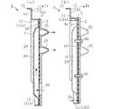
【解決手段】ガス供給用マニホールドAの蓋部材1は、本体部材2との重ね合わせ方向において、本体部材2とは反対側に屈曲して起立した屈曲起立壁部11を備え、かつこの屈曲起立壁部11は、蓋部材1と本体部材2との重ね合わせ方向視において、ガス供給流路29およびその周辺領域の全周を囲むループ状である。
【選択図】 図1
Description
ここで、ガス供給用マニホールドとしては、たとえば特許文献1,2に記載のものがある。
これらの文献に記載されたガス供給用マニホールドは、複数のガス噴出ノズルが設けられた本体部材と、この本体部材にシール用パッキンを介して重ね合わされる蓋部材とを備えている。蓋部材は、本体部材との間にガス供給流路を形成するための部材であり、本体部材に対し、たとえばビス止めによる締結が図られている。蓋部材および本体部材は、たとえば金属板にプレス加工を施すなどして形成されている。
このような構成によれば、ガス供給用マニホールドの部品総数を少なくして製造コストの低減化を図ることが可能である。また、全体の薄型化や軽量化も図ることが可能である。
なお、蓋部材の反り変形などを抑制する手段としては、たとえば本体部材に対する蓋部材のビス止め箇所の数を多くすることが考えられる。ただし、これでは、ビス止め作業が煩雑となり、製造コストが却って高くなる。また、ビス止め箇所の数を多くしたとしても、それだけでは蓋部材の反り変形などを十分に抑制することは難しい。
すなわち、蓋部材と本体部材との重ね合わせ方向視においてループ状に形成されている屈曲起立壁部は、蓋部材のガス供給流路形成領域およびその周辺領域の強度を大きく向上させる。このため、蓋部材の厚みを従来よりも薄くした場合であっても、蓋部材のガス供給流路形成領域およびその周辺領域に歪みを生じ難くし、本体部材との間でガス供給流路からのガス漏れの要因となる隙間を生じないようにすることが可能である。ガス漏れ防止策として、蓋部材と本体部材とのビス止め箇所などの数をかなり多くするといった必要もなくすことが可能である。このようなことから、本発明によれば、蓋部材の薄肉化を適切に図り、ガス供給用マニホールド全体の軽量化や製造コストの低減化などを好適に図ることが可能である。
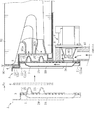
すなわち、図8などを参照して後述する内容からも理解されるように、たとえば屈曲起立壁部の多くの部分が、本体部材に重なった配置にはなく、本体部材からはみ出した配置に設けられているような場合と比較すると、前記構成によれば、蓋部材のガス供給流路の形成領域およびその周辺領域の強度をより向上させることが可能である。したがって、それらの領域の歪みなどを一層効果的に防止することができる。
図面には、矢印Frが適宜示されており、この方向を前方として説明する。
ートにプレス加工を施すことにより形成されたものである。
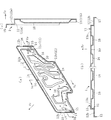
2aおよび左右両側部12bを有している。このフランジ部12には、ビス止め用の複数の孔部14が設けられており、このフランジ部12を利用してガス供給用マニホールドAを所望の取付け対象部位に取付け可能である。フランジ部12の外周縁には、このフランジ部12を補強するための屈曲片部15が設けられている。フランジ部12の外周縁には、屈曲片部15が設けられていない箇所16があるが、この箇所16は、蓋部材1を順送プレス加工により製作する場合に、この蓋部材1を支持するための部分に該当する。
屈曲起立壁部11を本体部材2に強く圧接させることができない。これに対し、本実施形態によれば、剛性の高い屈曲起立壁部11を本体部材2に強く圧接させることができる。また、これに加え、ループ状の屈曲起立壁部11によって囲まれる部分の面積を対比例の場合よりも小さくすることができる。このため、本実施形態では、ガス供給流路29およびその周辺領域を、一層効果的に補強することができる。
蓋部材と本体部材との連結は、ビス止めに限らず、たとえばビス以外のネジ体を用いる手段や、カシメなどの手段を用いて行なうことも可能である。
本発明に係るガス供給用マニホールドは、給湯装置の燃焼装置用に限定されず、その具体的な用途は限定されない。
1 蓋部材
11 屈曲起立壁部
12 フランジ部
13 位置決め用凸部
2 本体部材
22 凹部(本体部材の)
25 ガス噴出ノズル
29 ガス供給流路
3 シール用のパッキン
30 孔部(シール用のパッキンの)
4 ループ状パッキン
90 バーナケース(取付け対象部位)
Claims (5)
- 複数のガス噴出ノズルが設けられている本体部材と、
この本体部材の片面に重ねられ、かつ前記本体部材に連結されている蓋部材と、
を備えており、
前記蓋部材と前記本体部材との間には、前記複数のガス噴出ノズルに連通するガス供給流路が形成されている、ガス供給用マニホールドであって、
前記蓋部材は、前記本体部材との重ね合わせ方向において、前記本体部材とは反対側に屈曲して起立した屈曲起立壁部を備え、かつこの屈曲起立壁部は、前記蓋部材と前記本体部材との重ね合わせ方向視において、前記ガス供給流路およびその周辺領域の全周を囲むループ状に形成されていることを特徴とする、ガス供給用マニホールド。 - 請求項1に記載のガス供給用マニホールドであって、
前記重ね合わせ方向視において、前記屈曲起立壁部の略全周域は、前記本体部材に重なった配置に形成されている、ガス供給用マニホールド。 - 請求項1または2に記載のガス供給用マニホールドであって、
前記蓋部材と前記本体部材との相互間に介装されるシール用のパッキンを、備えており、
前記蓋部材には、前記パッキンに設けられている孔部に挿通する位置決め用凸部が形成されており、
前記本体部材には、前記位置決め用凸部の先端部が進入するように前記位置決め用凸部の突出方向に窪んだ非貫通孔状の凹部が設けられている、ガス供給用マニホールド。 - 請求項1ないし3のいずれかに記載のガス供給用マニホールドであって、
前記蓋部材には、前記屈曲起立壁部の先端部に繋がって屈曲し、かつ前記重ね合わせ方向視において、前記本体部材の外方にはみ出したフランジ部が設けられており、
このフランジ部は、所望の取付け対象部位への取付け部として用いられるように構成されている、ガス供給用マニホールド。 - 請求項4に記載のガス供給用マニホールドであって、
前記フランジ部は、前記本体部材の起立姿勢状態において、前記本体部材の上側および左右両側にはみ出すように設けられており、
このガス供給用マニホールドを前記取付け対象部位に取付ける際には、シール用のループ状パッキンの一部分が、前記本体部材の前面側のうち、前記複数のガス噴出ノズルの下側に位置して左右横幅方向に延び、かつ前記ループ状パッキンの他の部分が、前記フランジ部の前面側に位置するように設定される構成とされている、ガス供給用マニホールド。
Priority Applications (3)
| Application Number | Priority Date | Filing Date | Title |
|---|---|---|---|
| JP2016125930A JP6751258B2 (ja) | 2016-06-24 | 2016-06-24 | ガス供給用マニホールド |
| US15/624,393 US10309645B2 (en) | 2016-06-24 | 2017-06-15 | Gas supply manifold and gas combustion device provided with the same |
| CN201710457682.2A CN107543200B (zh) | 2016-06-24 | 2017-06-16 | 气体供给用歧管和具有该气体供给用歧管的气体燃烧装置 |
Applications Claiming Priority (1)
| Application Number | Priority Date | Filing Date | Title |
|---|---|---|---|
| JP2016125930A JP6751258B2 (ja) | 2016-06-24 | 2016-06-24 | ガス供給用マニホールド |
Publications (2)
| Publication Number | Publication Date |
|---|---|
| JP2017227422A true JP2017227422A (ja) | 2017-12-28 |
| JP6751258B2 JP6751258B2 (ja) | 2020-09-02 |
Family
ID=60676825
Family Applications (1)
| Application Number | Title | Priority Date | Filing Date |
|---|---|---|---|
| JP2016125930A Active JP6751258B2 (ja) | 2016-06-24 | 2016-06-24 | ガス供給用マニホールド |
Country Status (3)
| Country | Link |
|---|---|
| US (1) | US10309645B2 (ja) |
| JP (1) | JP6751258B2 (ja) |
| CN (1) | CN107543200B (ja) |
Cited By (2)
| Publication number | Priority date | Publication date | Assignee | Title |
|---|---|---|---|---|
| JP2021025739A (ja) * | 2019-08-08 | 2021-02-22 | リンナイ株式会社 | 給湯器 |
| KR20230142160A (ko) * | 2022-04-01 | 2023-10-11 | 한온시스템 주식회사 | 통합 급수 모듈 |
Families Citing this family (2)
| Publication number | Priority date | Publication date | Assignee | Title |
|---|---|---|---|---|
| US10288313B2 (en) * | 2015-12-25 | 2019-05-14 | Noritz Corporation | Gas supply manifold and production method of gas supply manifold |
| JP6751258B2 (ja) * | 2016-06-24 | 2020-09-02 | 株式会社ノーリツ | ガス供給用マニホールド |
Citations (2)
| Publication number | Priority date | Publication date | Assignee | Title |
|---|---|---|---|---|
| JP2003065507A (ja) * | 2001-08-23 | 2003-03-05 | Noritz Corp | ガス供給用マニホールド装置及びこれを備えたガス燃焼機器 |
| JP2015143588A (ja) * | 2014-01-31 | 2015-08-06 | リンナイ株式会社 | ガス供給用マニホールド |
Family Cites Families (13)
| Publication number | Priority date | Publication date | Assignee | Title |
|---|---|---|---|---|
| JP2004197971A (ja) | 2002-12-16 | 2004-07-15 | Noritz Corp | ガス供給用マニホールド装置及びこれを備えたガス燃焼機器 |
| JP2011252671A (ja) * | 2010-06-03 | 2011-12-15 | Rinnai Corp | 燃焼装置 |
| US9115891B2 (en) * | 2010-12-16 | 2015-08-25 | Noritz Corporation | Rich-lean combustion burner |
| US20120219920A1 (en) * | 2011-02-28 | 2012-08-30 | Noritz Corporation | Rich-lean combustion burner |
| JP5716551B2 (ja) * | 2011-05-30 | 2015-05-13 | 株式会社ノーリツ | 濃淡燃焼バーナ |
| CN103162290B (zh) * | 2011-12-09 | 2016-08-03 | 株式会社能率 | 浓淡火焰燃烧器及燃烧装置 |
| CN103185339B (zh) * | 2011-12-28 | 2016-08-03 | 株式会社能率 | 浓淡火焰燃烧器及燃烧装置 |
| CN103727133A (zh) * | 2012-10-15 | 2014-04-16 | 洛阳伊崧精密轴承技术开发有限公司 | 一种圆锥滚子轴承用的全冲压保持架结构 |
| JP5997872B2 (ja) * | 2014-04-02 | 2016-09-28 | リンナイ株式会社 | ガス供給用マニホールド |
| US20150369479A1 (en) * | 2014-06-20 | 2015-12-24 | Rinnai Corporation | Flat burner |
| JP6504520B2 (ja) * | 2015-03-26 | 2019-04-24 | 株式会社ノーリツ | 燃焼装置 |
| US10288313B2 (en) * | 2015-12-25 | 2019-05-14 | Noritz Corporation | Gas supply manifold and production method of gas supply manifold |
| JP6751258B2 (ja) * | 2016-06-24 | 2020-09-02 | 株式会社ノーリツ | ガス供給用マニホールド |
-
2016
- 2016-06-24 JP JP2016125930A patent/JP6751258B2/ja active Active
-
2017
- 2017-06-15 US US15/624,393 patent/US10309645B2/en active Active
- 2017-06-16 CN CN201710457682.2A patent/CN107543200B/zh active Active
Patent Citations (2)
| Publication number | Priority date | Publication date | Assignee | Title |
|---|---|---|---|---|
| JP2003065507A (ja) * | 2001-08-23 | 2003-03-05 | Noritz Corp | ガス供給用マニホールド装置及びこれを備えたガス燃焼機器 |
| JP2015143588A (ja) * | 2014-01-31 | 2015-08-06 | リンナイ株式会社 | ガス供給用マニホールド |
Cited By (4)
| Publication number | Priority date | Publication date | Assignee | Title |
|---|---|---|---|---|
| JP2021025739A (ja) * | 2019-08-08 | 2021-02-22 | リンナイ株式会社 | 給湯器 |
| JP7274255B2 (ja) | 2019-08-08 | 2023-05-16 | リンナイ株式会社 | 給湯器 |
| KR20230142160A (ko) * | 2022-04-01 | 2023-10-11 | 한온시스템 주식회사 | 통합 급수 모듈 |
| KR102926765B1 (ko) | 2022-04-01 | 2026-02-12 | 한온시스템 주식회사 | 통합 급수 모듈 |
Also Published As
| Publication number | Publication date |
|---|---|
| CN107543200B (zh) | 2021-05-07 |
| US20170370574A1 (en) | 2017-12-28 |
| CN107543200A (zh) | 2018-01-05 |
| JP6751258B2 (ja) | 2020-09-02 |
| US10309645B2 (en) | 2019-06-04 |
Similar Documents
| Publication | Publication Date | Title |
|---|---|---|
| JP6538545B2 (ja) | 燃焼装置 | |
| JP2017227422A (ja) | ガス供給用マニホールド | |
| KR102448142B1 (ko) | 전1차 연소식 버너 | |
| US8117835B2 (en) | Gasket | |
| JP5921584B2 (ja) | ガス供給用マニホールド | |
| JPH11337288A (ja) | 熱交換器 | |
| WO2017006758A1 (ja) | 給湯器 | |
| JP2006284127A (ja) | ガスタービン燃焼器 | |
| KR20090057362A (ko) | 머플러에 있어서의 배기관 접속부 구조 | |
| JP2008292032A (ja) | 金属部材の接合構造およびこの構造を備えた金属製ケース | |
| JP2017116209A (ja) | ガス供給用マニホールドおよびその製造方法 | |
| JP6475092B2 (ja) | 燃焼装置 | |
| JP2018031551A (ja) | バーナケースの製造方法およびバーナケース | |
| JP6691439B2 (ja) | 熱源機 | |
| JP6080089B2 (ja) | 湯水混合水栓装置 | |
| JP2007303602A (ja) | シリンダヘッドガスケット | |
| JP4850221B2 (ja) | グリル用バーナ | |
| JP2010505068A (ja) | 封止具 | |
| JP4707699B2 (ja) | 内燃機関における排気マニホールド | |
| JP2022129854A (ja) | 冷却ユニット | |
| JP2005155713A (ja) | 金属ガスケット | |
| JP2008223581A (ja) | 金属ガスケット | |
| JP4644096B2 (ja) | 内燃機関の二次空気供給構造 | |
| JP6880399B2 (ja) | ガスケット | |
| JP4935297B2 (ja) | 熱源機 |
Legal Events
| Date | Code | Title | Description |
|---|---|---|---|
| A621 | Written request for application examination |
Free format text: JAPANESE INTERMEDIATE CODE: A621 Effective date: 20190530 |
|
| A977 | Report on retrieval |
Free format text: JAPANESE INTERMEDIATE CODE: A971007 Effective date: 20200311 |
|
| A131 | Notification of reasons for refusal |
Free format text: JAPANESE INTERMEDIATE CODE: A131 Effective date: 20200318 |
|
| A521 | Request for written amendment filed |
Free format text: JAPANESE INTERMEDIATE CODE: A523 Effective date: 20200507 |
|
| TRDD | Decision of grant or rejection written | ||
| A01 | Written decision to grant a patent or to grant a registration (utility model) |
Free format text: JAPANESE INTERMEDIATE CODE: A01 Effective date: 20200715 |
|
| A61 | First payment of annual fees (during grant procedure) |
Free format text: JAPANESE INTERMEDIATE CODE: A61 Effective date: 20200728 |
|
| R150 | Certificate of patent or registration of utility model |
Ref document number: 6751258 Country of ref document: JP Free format text: JAPANESE INTERMEDIATE CODE: R150 |