JP2017228497A - Assembled battery bus bar and assembled battery - Google Patents
Assembled battery bus bar and assembled battery Download PDFInfo
- Publication number
- JP2017228497A JP2017228497A JP2016125701A JP2016125701A JP2017228497A JP 2017228497 A JP2017228497 A JP 2017228497A JP 2016125701 A JP2016125701 A JP 2016125701A JP 2016125701 A JP2016125701 A JP 2016125701A JP 2017228497 A JP2017228497 A JP 2017228497A
- Authority
- JP
- Japan
- Prior art keywords
- connection portion
- bus bar
- battery
- electrode terminal
- assembled battery
- Prior art date
- Legal status (The legal status is an assumption and is not a legal conclusion. Google has not performed a legal analysis and makes no representation as to the accuracy of the status listed.)
- Pending
Links
Images


Classifications
-
- Y—GENERAL TAGGING OF NEW TECHNOLOGICAL DEVELOPMENTS; GENERAL TAGGING OF CROSS-SECTIONAL TECHNOLOGIES SPANNING OVER SEVERAL SECTIONS OF THE IPC; TECHNICAL SUBJECTS COVERED BY FORMER USPC CROSS-REFERENCE ART COLLECTIONS [XRACs] AND DIGESTS
- Y02—TECHNOLOGIES OR APPLICATIONS FOR MITIGATION OR ADAPTATION AGAINST CLIMATE CHANGE
- Y02E—REDUCTION OF GREENHOUSE GAS [GHG] EMISSIONS, RELATED TO ENERGY GENERATION, TRANSMISSION OR DISTRIBUTION
- Y02E60/00—Enabling technologies; Technologies with a potential or indirect contribution to GHG emissions mitigation
- Y02E60/10—Energy storage using batteries
Landscapes
- Connection Of Batteries Or Terminals (AREA)
- Battery Mounting, Suspending (AREA)
Abstract
【課題】本発明は複数の電池セルの配列を変えることなく、他の組電池といった外部との接続距離を短くすることのできる組電池用のバスバー及び組電池を提供することを目的とする。【解決手段】複数の二次電池を並列配置したときに端部に位置する二次電池の正極端子または負極端子と接続されるバスバーであって、前記正極端子または前記負極端子に取り付けられたときに、二次電池の前記正極端子および前記負極端子が設けられた面と略平行な第一の接続部と、前記第一の接続部と略平行な第二の接続部と、前記第二の接続部と略直角な第三の接続部と、前記第二の接続部および前記第三の接続部と略直角な第四の接続部と、を備えている組電池用バスバー。【選択図】図1An object of the present invention is to provide an assembled battery bus bar and an assembled battery that can shorten the connection distance to the outside, such as another assembled battery, without changing the arrangement of a plurality of battery cells. A bus bar connected to a positive electrode terminal or a negative electrode terminal of a secondary battery located at an end when a plurality of secondary batteries are arranged in parallel when the secondary battery is attached to the positive electrode terminal or the negative electrode terminal A first connection portion substantially parallel to a surface of the secondary battery on which the positive electrode terminal and the negative electrode terminal are provided, a second connection portion substantially parallel to the first connection portion, and the second connection portion. A battery pack bus bar comprising: a third connection portion substantially perpendicular to the connection portion; and a fourth connection portion substantially perpendicular to the second connection portion and the third connection portion. [Selection] Figure 1
Description
本発明の実施形態は、組電池用バスバー及び組電池に関する。 Embodiments described herein relate generally to an assembled battery bus bar and an assembled battery.
蓄電池等の分野においては、所望の電力を取り出すために出力の小さい電池セルを複数
接続し、1個の組電池を構成することは広く行われている。そのような組電池では、隣接
した電池セルの各電極は平板状のバスバーで接続される。
In the field of storage batteries and the like, it is widely practiced to connect a plurality of battery cells having a small output in order to take out desired power to form one assembled battery. In such a battery pack, the electrodes of adjacent battery cells are connected by a flat bus bar.
このようにして複数の電池セルを接続する場合、組電池における電池セルは組電池の体
積が最も小さくなるように配列されることが多い。そのため、電池セルの配列は電池セル
の個数等によって一意的に決まり、複数の電池セルを接続した電池セル群の両端にあたる
電池セルの正極又は負極の位置も一意的に決まってしまうことがある。
When a plurality of battery cells are connected in this way, the battery cells in the assembled battery are often arranged so that the volume of the assembled battery is minimized. Therefore, the arrangement of the battery cells is uniquely determined by the number of battery cells and the like, and the positions of the positive and negative electrodes of the battery cells corresponding to both ends of the battery cell group in which a plurality of battery cells are connected may be uniquely determined.
一方、例えば、組電池同士を接続する際その接続配線は短い方が好ましいが、前記電池
セル群の両端にあたる電池セルの正極又は負極の位置は、必ずしも組電池同士を接続する
際にその配線が短くなるような位置となっているとは限らない。
On the other hand, for example, when connecting assembled batteries, it is preferable that the connection wiring is short, but the position of the positive electrode or the negative electrode of the battery cells corresponding to both ends of the battery cell group is not necessarily the same when connecting the assembled batteries. The position is not necessarily shortened.
そこで、本発明は複数の電池セルの配列を変えることなく、他の組電池といった外部と
の接続距離を短くすることのできる組電池用のバスバー及び組電池を提供することを目的
とする。
Accordingly, an object of the present invention is to provide an assembled battery bus bar and an assembled battery that can shorten the connection distance to the outside, such as another assembled battery, without changing the arrangement of a plurality of battery cells.
上記の課題を解決するために、本実施形態の組電池用バスバーは、
複数の二次電池を並列配置したときに端部に位置する二次電池の正極端子または負極端
子と接続されるバスバーであって、
前記正極端子または前記負極端子に取り付けられたときに、二次電池の前記正極端子お
よび前記負極端子が設けられた面と略平行な第一の接続部と、
前記第一の接続部と略平行な第二の接続部と、
前記第二の接続部と略直角な第三の接続部と、
前記第二の接続部および前記第三の接続部と略直角な第四の接続部と、
を備えている。
In order to solve the above problems, the battery pack bus bar of the present embodiment is
A bus bar connected to a positive terminal or a negative terminal of a secondary battery located at an end when a plurality of secondary batteries are arranged in parallel,
When attached to the positive electrode terminal or the negative electrode terminal, a first connection portion substantially parallel to the surface of the secondary battery on which the positive electrode terminal and the negative electrode terminal are provided;
A second connection portion substantially parallel to the first connection portion;
A third connection portion substantially perpendicular to the second connection portion;
A fourth connection portion substantially perpendicular to the second connection portion and the third connection portion;
It has.
以下、実施形態を図面に基づき説明する。 Hereinafter, embodiments will be described with reference to the drawings.
(第1の実施形態)
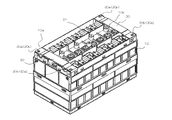
図1は、実施形態に係る組電池1の斜視図である。組電池1の筐体12は、上面が開口
した矩形箱状の下部ケース16と、この下部ケース16の開口している上面側を覆う上部
ケース18と、更に、上部ケースの下部ケース16と反対側を覆うカバー20と、から構
成される。そして、筐体12の内部に複数の電池セル10が収容される。
(First embodiment)
FIG. 1 is a perspective view of an assembled
なお、筐体12の各部品には、絶縁性を有した合成樹脂材料(例えば、変性PPE(ポ
リフェニレンエーテル)や、PFA(パーフルオロアルコキシアルカン、テトラフルオロ
エチレン・パーフルオロアルキルビニルエーテル共重合体)等)が用いられている。また
、筐体12の合成樹脂材料としては、熱可塑性樹脂を用いることができ、例えば、PEや
、PP、PMP等のオレフィン樹脂、PETや、PBT、PEN等のポリエステル系樹脂
、POM樹脂、PA6、PA66、PA12等のポリアミド系樹脂、PPS樹脂、LCP
樹脂等の結晶性樹脂およびそれらのアロイ樹脂、あるいは、PSや、PC、PC/ABS
、ABS、AS、変性PPE、PES、PEI、PSF等の非結晶性樹脂およびそれらの
アロイ樹脂を、用いることができる。
Each component of the housing 12 has an insulating synthetic resin material (for example, modified PPE (polyphenylene ether), PFA (perfluoroalkoxyalkane, tetrafluoroethylene / perfluoroalkyl vinyl ether copolymer), etc.) ) Is used. Further, as the synthetic resin material of the housing 12, a thermoplastic resin can be used. For example, olefin resin such as PE, PP, PMP, polyester resin such as PET, PBT, PEN, POM resin, PA6. , PA66, PA12 and other polyamide resins, PPS resins, LCP
Crystalline resins such as resins and their alloy resins, or PS, PC, PC / ABS
, ABS, AS, modified PPE, PES, PEI, PSF, and other amorphous resins and their alloy resins can be used.
図2は、電池セル10を示している。電池セル10は、例えば、リチウムイオン電池な
どの非水電解質二次電池であり、例えば、アルミニウムまたはアルミニウム合金で形成さ
れた扁平又は略直方形状の外装容器2と、外装容器2内に非水電解液と共に収納された電
極体(図示しない)と、を備えている。
FIG. 2 shows the
外装容器2は、上端が開口した容器本体2aと、容器本体2aに溶接されて容器本体2
aの開口を閉塞した矩形板状の蓋体2bとから成り、そして内部が液密に形成されている
。外装容器2の容器本体2aは、一対の長側面43と、長側面43より短い一対の短側面
44と、により構成されている。また、外装容器2の蓋体2bは、正極端子3及び負極端
子4を備えており、正極端子3及び負極端子4は電極体に電気的に接続されている。また
、電池セル10内に発生したガスを排出するガス排出弁5を備え、さらに、電解液を電池
セル10内に注入するための注液孔6及び、注液孔6を封止する封止板7等を有している
。
The
It consists of a rectangular plate-
電極体は、例えば、正極板および負極板をその間にセパレータを介在されて渦巻き状に
巻回し、更に、径方向に圧縮することにより、偏平な矩形状に形成されている。
For example, the electrode body is formed in a flat rectangular shape by winding a positive electrode plate and a negative electrode plate in a spiral shape with a separator interposed therebetween, and further compressing the electrode plate in the radial direction.
図3は、カバー20がとり外されている状態の組電池1の斜視図である。また、図3は
電池セル10を9個直列に接続した例を示しており、電池セル10は長側面43同士を対
向させて組電池1内に配列され、電池セル群を構成する。さらに、正極端子3および負極
端子4は、それぞれ上部ケース18に取り付けられたバスバー21によって他の電池セル
10の正極端子3または負極端子4と電気的に接続される。なお、バスバー21は、導電
性のアルミニウムや真鍮等の金属板を曲げて成形して形成さる。
FIG. 3 is a perspective view of the
さらに、電池セル群の両端部に配置される電池セル10aおよび電池セル10bがそれ
ぞれの有する2つの電極端子、すなわち、正極端子3および負極端子4の一方は、図4に
示すバスバー22に接続されている。バスバー22は、例えば、組電池1の矩形上部ケー
ス18における角部(4隅部)に設けられている。バスバー22は、電池セル10の正極
端子3及び負極端子4のうちの一方と、組電池1の外部(例えば、他の組電池若しくはモ
ーターなどの負荷)とを接続できる構造となっている。
Further, two electrode terminals respectively possessed by the battery cell 10a and the battery cell 10b arranged at both ends of the battery cell group, that is, one of the
バスバー22は、導電性のアルミニウムや真鍮等の金属板を曲げることで形成されてお
り、電池セル10の端子に接続するための、例えば溶接用の孔26aを有する第一の接続
部26を備えている。第一の接続部26は例えば、電池セル10の端子面と略平行であり
、電気的に接続されている。
The bus bar 22 is formed by bending a metal plate such as conductive aluminum or brass, and includes a first connection portion 26 having, for example, a welding hole 26 a for connecting to the terminal of the
また、バスバー22は、第一の接続部26から略直角方向に延伸した継手部28を備え
、さらに継手部28から略直角方向に延伸した第二の接続部23を備える。さらに、第二
の接続部23からは略直角方向に延伸した第三の接続部24及び第四の接続部25を備え
る。それぞれ第三の接続部24及び第四の接続部25は略直交するように配置されている
。また、例えば、他の組電池などと接続するためのハーネスと、接続部23とを例えばネ
ジにより接続するため、孔23aを第二の接続部23に、孔24aを第三の接続部24に
、孔25aを第四の接続部25に形成している。
The bus bar 22 includes a joint portion 28 extending from the first connection portion 26 in a substantially right angle direction, and further includes a second connection portion 23 extending from the joint portion 28 in a substantially right angle direction. Furthermore, the second connection part 23 includes a
さらに、バスバー22には、制御回路基板(図示略)などにねじ止め固定されるための
孔27aが形成された接続片27が設けられている。
Further, the bus bar 22 is provided with a connection piece 27 in which a hole 27a for screwing and fixing to a control circuit board (not shown) or the like is formed.
ここで第二の接続部23は、例えば、第一の接続部26およびカバー20の上面と略平
行な平面を形成している。さらに、第三の接続部24は、例えば上部ケース18の長側面
と略平行な平面を形成し、第四の接続部25は、例えば上部ケース18の短側面と略平行
な平面を形成している。
Here, the second connection portion 23 forms a plane substantially parallel to the first connection portion 26 and the upper surface of the cover 20, for example. Further, the
ここで、第一の接続部26と継手部28とは屈曲部31によって接続され、継手部28
と第二の接続部23とは屈曲部32によって接続され、第二の接続部23と第三の接続部
24とは屈曲部34によって接続され、第二の接続部23と第四の接続部25とは屈曲部
33によって接続されている。ここで、屈曲部31、32、33、34は略90度の曲げ
角度を有するものであってもよいし、90度以上の曲げ角度を有していてもよい。
Here, the first connection part 26 and the joint part 28 are connected by a bent part 31, and the joint part 28 is connected.
And the second connecting portion 23 are connected by a bent portion 32, the second connecting portion 23 and the third connecting
また、図3に示すように、電池セル群の両端部に配置される電池セル10aおよび電池
セル10bはバスバー22を経て、バスバー30に電気的に接続されている。
Further, as shown in FIG. 3, the battery cells 10 a and the battery cells 10 b arranged at both ends of the battery cell group are electrically connected to the
バスバー30は、例えばカバー20とバスバー22と上部ケース18との間に設置され
た制御回路基板(図示略)とで形成された空間に配置されている。また、バスバー30は
電池セル群の配列方向に対して直交する方向に延伸され、電池セル10aおよび電池セル
10bに接続されていないバスバー22に対して電気的に接続できるように延伸されてい
る。
The
バスバー30の端部には、第一の接続バスバー22と例えばネジにより接続するための
孔30aおよび孔30bを備えており、また、バスバー30は導電性のアルミニウムや真
鍮等の金属板を曲げて成形して形成されている。
The end of the
図1に示すように、カバー20の例えば、上面における角部(4隅部)には、バスバー
22およびバスバー30に設けられた孔に対してねじが挿通できる孔50を有する。また
、上部ケース18の角部(4隅部)及びカバー20側面の角部(4隅部)には、バスバー
22およびバスバー30に設けられた孔に対してねじが挿通できる切欠き部51を有する
。
As shown in FIG. 1, for example, a corner (four corners) on the upper surface of the cover 20 has a hole 50 through which a screw can be inserted into a hole provided in the bus bar 22 and the
以上のような実施形態によると、バスバー22の第二の接続部23又は第三の接続部2
4又は第四の接続部25から、外部、例えば、モーターなどの外部付加、他の組電池1、
充放電装置等と接続することが可能となる。すなわち、互いに直角な3方向から外部に対
して電気的に接続することが可能となる。よって、バスバーから外部に接続できる方向が
1方向のみの場合と比較して、組電池1と外部との接続距離を短くすることができ、接続
部材が節約できる。また、接続距離を短くすることができる為、組電池1及び組電池1と
接続するその他機器の設置スペースを小さくすることができる為、組電池1及び組電池1
と接続するその他機器を含めた体積エネルギー密度を向上することが可能となる。また、
組電池1等の組み合わせ方の自由度が向上することで、限られたスペースであっても設置
することが容易となる。
According to the embodiment as described above, the second connection portion 23 or the
4 or the fourth connecting portion 25, externally, for example, external addition such as a motor, other assembled
It becomes possible to connect to a charge / discharge device or the like. That is, it is possible to electrically connect to the outside from three directions perpendicular to each other. Therefore, compared with the case where only one direction can be connected from the bus bar to the outside, the connection distance between the assembled
It is possible to improve the volume energy density including other devices connected to the. Also,
By improving the degree of freedom in combining the assembled
また、例えば、複数の電池セル10を電池セル10の長側面43同士を対面させて直列
に接続して組電池1内に収容するとき、複数の電池セル10を接続した電池セル群の一端
の正極と、他端の負極の位置は一意的に決まる。例えば、図3のように、9個の電池セル
10を直列に接続した時、9個の電池セル10を接続した電池セル群の一端の正極と、他
端の負極は、電池セル群を電極の有する側から見た時の電池セル群を四角形と捉えると、
対角線状に位置する。同様に、10個の電池セル10を直列に接続した電池セル群の一端
の正極と、他端の負極は、電池セル群を電極の有する側から見た時の電池セル群を四角形
と捉えると、同一辺上に位置する。
Further, for example, when the
Located diagonally. Similarly, the positive electrode at one end and the negative electrode at the other end of the battery cell group in which ten
ここで、例えば並列若しくは直列に電気的に接続された電池セル群の一端の正極に対し
て、例えば、バスバー22(ここではバスバー22a)を介してバスバー30に電気的に
接続され、バスバー30が、電池セル10に電気的に接続されていないバスバー22に対
して電気的に接続されることにより、バスバー22とは異なる位置から、バスバー22を
介して外部に対に電気的に接続することができる。よって、従来外部に対して接続できる
箇所が電池セルの配列によって一意的に決まっていたところ、バスバー30を用いること
で、外部に接続できる箇所を適宜変更することができる。よって、組電池1と外部との接
続距離を短くすることが可能となり、接続部材が節約できる。また、接続距離を短くする
ことができる為、組電池1及び組電池1と接続するその他機器の設置スペースを小さくす
ることができる為、組電池1及び組電池1と接続するその他機器を含めた体積エネルギー
密度を向上することが可能となる。また、組電池1等の組み合わせ方の自由度が向上する
ことで、限られたスペースであっても設置することが容易となる。
Here, for example, the positive electrode at one end of the battery cell group electrically connected in parallel or in series is electrically connected to the
また、バスバー22及びバスバー30を組み合わせることで、組電池1は、電池セル1
0の配列に依存することなく、任意の箇所で、任意の方向に対して電気を外部に取り出す
ことが可能となり、組電池1等の省スペース化、高エネルギー密度化、組電池1等の組み
合わせ方自由度の向上が可能となる。
Further, by combining the bus bar 22 and the
Without depending on the arrangement of 0, it becomes possible to take out electricity in an arbitrary place in an arbitrary direction, space saving of the assembled
本発明のいくつかの実施形態を説明したが、これらの実施形態は、例として提示したも
のであり、発明の範囲を限定することは意図していない。これら実施形態は、その他の様
々な形態で実施されることが可能であり、発明の要旨を逸脱しない範囲で、種々の省略、
置き換え、変更を行うことができる。これら実施形態やその変形は、発明の範囲や要旨に
含まれると同様に、特許請求の範囲に記載された発明とその均等の範囲に含まれるもので
ある。
Although several embodiments of the present invention have been described, these embodiments are presented by way of example and are not intended to limit the scope of the invention. These embodiments can be implemented in various other forms, and various omissions can be made without departing from the spirit of the invention.
Can be replaced or changed. These embodiments and their modifications are included in the scope and gist of the invention, and are also included in the invention described in the claims and the equivalents thereof.
1…組電池、2…外装容器、3…正極端子、4…負極端子、5…ガス排出弁、6…注液孔
、7…封止板、10…電池セル、16…下部ケース、18…上部ケース、20…カバー、
21、22、30…バスバー、26…第一の接続部、23…第二の接続部、24…第三の
接続部、25…第四の接続部、50…孔、51…切欠き部
DESCRIPTION OF
21, 22, 30 ... bus bar, 26 ... first connection part, 23 ... second connection part, 24 ... third connection part, 25 ... fourth connection part, 50 ... hole, 51 ... notch part
Claims (3)
子と接続されるバスバーであって、
前記正極端子または前記負極端子に取り付けられたときに、二次電池の前記正極端子お
よび前記負極端子が設けられた面と略平行な第一の接続部と、
前記第一の接続部と略平行な第二の接続部と、
前記第二の接続部と略直角な第三の接続部と、
前記第二の接続部および前記第三の接続部と略直角な第四の接続部と、
を備えた、組電池用バスバー。 A bus bar connected to a positive terminal or a negative terminal of a secondary battery located at an end when a plurality of secondary batteries are arranged in parallel,
When attached to the positive electrode terminal or the negative electrode terminal, a first connection portion substantially parallel to the surface of the secondary battery on which the positive electrode terminal and the negative electrode terminal are provided;
A second connection portion substantially parallel to the first connection portion;
A third connection portion substantially perpendicular to the second connection portion;
A fourth connection portion substantially perpendicular to the second connection portion and the third connection portion;
A battery pack bus bar.
され、前記第四の接続部は前記ケースの1つの側面に直交する側面と並行に配置される、
請求項1の組電池用バスバー。 The third connection portion is disposed in parallel with one side surface of the case accommodating the plurality of secondary batteries, and the fourth connection portion is disposed in parallel with a side surface orthogonal to the one side surface of the case. The
The assembled battery bus bar according to claim 1.
前記二次電池の正極端子または負極端子に取り付けられたときに、前記二次電池の前記
正極端子および前記負極端子が設けられた面と略平行な第一の接続部と、前記第一の接続
部と略平行な第二の接続部と、前記第二の接続部と略直角な第三の接続部と、前記第二の
接続部および前記第三の接続部と略直角な第四の接続部と、を有した組電池用バスバーと
、
を備えた、略直方体型の組電池。 A plurality of secondary batteries;
A first connection portion substantially parallel to a surface of the secondary battery on which the positive electrode terminal and the negative electrode terminal are provided, and the first connection when attached to the positive electrode terminal or the negative electrode terminal of the secondary battery. A second connection portion substantially parallel to the second connection portion, a third connection portion substantially perpendicular to the second connection portion, and a fourth connection substantially perpendicular to the second connection portion and the third connection portion. A battery pack bus bar having a portion,
A substantially rectangular parallelepiped assembled battery.
Priority Applications (1)
| Application Number | Priority Date | Filing Date | Title |
|---|---|---|---|
| JP2016125701A JP2017228497A (en) | 2016-06-24 | 2016-06-24 | Assembled battery bus bar and assembled battery |
Applications Claiming Priority (1)
| Application Number | Priority Date | Filing Date | Title |
|---|---|---|---|
| JP2016125701A JP2017228497A (en) | 2016-06-24 | 2016-06-24 | Assembled battery bus bar and assembled battery |
Publications (1)
| Publication Number | Publication Date |
|---|---|
| JP2017228497A true JP2017228497A (en) | 2017-12-28 |
Family
ID=60891960
Family Applications (1)
| Application Number | Title | Priority Date | Filing Date |
|---|---|---|---|
| JP2016125701A Pending JP2017228497A (en) | 2016-06-24 | 2016-06-24 | Assembled battery bus bar and assembled battery |
Country Status (1)
| Country | Link |
|---|---|
| JP (1) | JP2017228497A (en) |
Cited By (2)
| Publication number | Priority date | Publication date | Assignee | Title |
|---|---|---|---|---|
| CN114447528A (en) * | 2022-02-28 | 2022-05-06 | 中创新航科技股份有限公司 | Busbar and battery pack |
| CN115347327A (en) * | 2021-05-14 | 2022-11-15 | 中创新航科技股份有限公司 | Battery pack and battery pack grouping method |
-
2016
- 2016-06-24 JP JP2016125701A patent/JP2017228497A/en active Pending
Cited By (2)
| Publication number | Priority date | Publication date | Assignee | Title |
|---|---|---|---|---|
| CN115347327A (en) * | 2021-05-14 | 2022-11-15 | 中创新航科技股份有限公司 | Battery pack and battery pack grouping method |
| CN114447528A (en) * | 2022-02-28 | 2022-05-06 | 中创新航科技股份有限公司 | Busbar and battery pack |
Similar Documents
| Publication | Publication Date | Title |
|---|---|---|
| JP6257951B2 (en) | Battery module | |
| US20120129042A1 (en) | Battery module | |
| US10903463B2 (en) | Battery pack | |
| JP6629140B2 (en) | Power storage module | |
| JP2011165628A (en) | Secondary battery device | |
| WO2020105502A1 (en) | Power storage module | |
| JP2018032560A (en) | Power storage device | |
| JP6891597B2 (en) | Power storage device | |
| JP7605204B2 (en) | Energy storage facilities | |
| JP2019114372A (en) | Power storage device | |
| JP2021157978A (en) | Power storage device | |
| JP2019003843A (en) | Power storage device | |
| JP2017228497A (en) | Assembled battery bus bar and assembled battery | |
| JP2021157984A (en) | Power storage device | |
| JP2019053928A (en) | Assembled battery | |
| US20240145816A1 (en) | Energy storage apparatus | |
| JP6926668B2 (en) | Power storage device | |
| JP7098355B2 (en) | Battery module and assembled battery | |
| JP2020161416A (en) | Power storage device | |
| JP7102117B2 (en) | Connecting member | |
| JPWO2020137410A1 (en) | Power storage device | |
| US20130143106A1 (en) | Lithium ion battery | |
| US12341220B2 (en) | Energy storage apparatus | |
| JP2019079599A (en) | Power storage device | |
| JP2021531616A (en) | Battery cell connector and battery cell structure connected via this connector |
Legal Events
| Date | Code | Title | Description |
|---|---|---|---|
| A711 | Notification of change in applicant |
Free format text: JAPANESE INTERMEDIATE CODE: A712 Effective date: 20170921 Free format text: JAPANESE INTERMEDIATE CODE: A711 Effective date: 20170921 |
|
| RD03 | Notification of appointment of power of attorney |
Free format text: JAPANESE INTERMEDIATE CODE: A7423 Effective date: 20180831 |
|
| RD03 | Notification of appointment of power of attorney |
Free format text: JAPANESE INTERMEDIATE CODE: A7423 Effective date: 20190125 |
|
| A711 | Notification of change in applicant |
Free format text: JAPANESE INTERMEDIATE CODE: A712 Effective date: 20190606 |
|
| RD07 | Notification of extinguishment of power of attorney |
Free format text: JAPANESE INTERMEDIATE CODE: A7427 Effective date: 20190606 |