JP2017504355A - Non-contact infrared thermal cycle - Google Patents
Non-contact infrared thermal cycle Download PDFInfo
- Publication number
- JP2017504355A JP2017504355A JP2016557876A JP2016557876A JP2017504355A JP 2017504355 A JP2017504355 A JP 2017504355A JP 2016557876 A JP2016557876 A JP 2016557876A JP 2016557876 A JP2016557876 A JP 2016557876A JP 2017504355 A JP2017504355 A JP 2017504355A
- Authority
- JP
- Japan
- Prior art keywords
- temperature
- reaction chamber
- fluid
- heat source
- heating
- Prior art date
- Legal status (The legal status is an assumption and is not a legal conclusion. Google has not performed a legal analysis and makes no representation as to the accuracy of the status listed.)
- Pending
Links
Images




Classifications
-
- B—PERFORMING OPERATIONS; TRANSPORTING
- B01—PHYSICAL OR CHEMICAL PROCESSES OR APPARATUS IN GENERAL
- B01L—CHEMICAL OR PHYSICAL LABORATORY APPARATUS FOR GENERAL USE
- B01L7/00—Heating or cooling apparatus; Heat insulating devices
- B01L7/52—Heating or cooling apparatus; Heat insulating devices with provision for submitting samples to a predetermined sequence of different temperatures, e.g. for treating nucleic acid samples
-
- B—PERFORMING OPERATIONS; TRANSPORTING
- B01—PHYSICAL OR CHEMICAL PROCESSES OR APPARATUS IN GENERAL
- B01L—CHEMICAL OR PHYSICAL LABORATORY APPARATUS FOR GENERAL USE
- B01L3/00—Containers or dishes for laboratory use, e.g. laboratory glassware; Droppers
- B01L3/50—Containers for the purpose of retaining a material to be analysed, e.g. test tubes
- B01L3/502—Containers for the purpose of retaining a material to be analysed, e.g. test tubes with fluid transport, e.g. in multi-compartment structures
- B01L3/5027—Containers for the purpose of retaining a material to be analysed, e.g. test tubes with fluid transport, e.g. in multi-compartment structures by integrated microfluidic structures, i.e. dimensions of channels and chambers are such that surface tension forces are important, e.g. lab-on-a-chip
-
- C—CHEMISTRY; METALLURGY
- C12—BIOCHEMISTRY; BEER; SPIRITS; WINE; VINEGAR; MICROBIOLOGY; ENZYMOLOGY; MUTATION OR GENETIC ENGINEERING
- C12Q—MEASURING OR TESTING PROCESSES INVOLVING ENZYMES, NUCLEIC ACIDS OR MICROORGANISMS; COMPOSITIONS OR TEST PAPERS THEREFOR; PROCESSES OF PREPARING SUCH COMPOSITIONS; CONDITION-RESPONSIVE CONTROL IN MICROBIOLOGICAL OR ENZYMOLOGICAL PROCESSES
- C12Q1/00—Measuring or testing processes involving enzymes, nucleic acids or microorganisms; Compositions therefor; Processes of preparing such compositions
- C12Q1/68—Measuring or testing processes involving enzymes, nucleic acids or microorganisms; Compositions therefor; Processes of preparing such compositions involving nucleic acids
- C12Q1/6844—Nucleic acid amplification reactions
- C12Q1/686—Polymerase chain reaction [PCR]
-
- B—PERFORMING OPERATIONS; TRANSPORTING
- B01—PHYSICAL OR CHEMICAL PROCESSES OR APPARATUS IN GENERAL
- B01L—CHEMICAL OR PHYSICAL LABORATORY APPARATUS FOR GENERAL USE
- B01L2200/00—Solutions for specific problems relating to chemical or physical laboratory apparatus
- B01L2200/14—Process control and prevention of errors
- B01L2200/143—Quality control, feedback systems
- B01L2200/147—Employing temperature sensors
-
- B—PERFORMING OPERATIONS; TRANSPORTING
- B01—PHYSICAL OR CHEMICAL PROCESSES OR APPARATUS IN GENERAL
- B01L—CHEMICAL OR PHYSICAL LABORATORY APPARATUS FOR GENERAL USE
- B01L2300/00—Additional constructional details
- B01L2300/06—Auxiliary integrated devices, integrated components
- B01L2300/0627—Sensor or part of a sensor is integrated
-
- B—PERFORMING OPERATIONS; TRANSPORTING
- B01—PHYSICAL OR CHEMICAL PROCESSES OR APPARATUS IN GENERAL
- B01L—CHEMICAL OR PHYSICAL LABORATORY APPARATUS FOR GENERAL USE
- B01L2300/00—Additional constructional details
- B01L2300/08—Geometry, shape and general structure
- B01L2300/0809—Geometry, shape and general structure rectangular shaped
- B01L2300/0816—Cards, e.g. flat sample carriers usually with flow in two horizontal directions
-
- B—PERFORMING OPERATIONS; TRANSPORTING
- B01—PHYSICAL OR CHEMICAL PROCESSES OR APPARATUS IN GENERAL
- B01L—CHEMICAL OR PHYSICAL LABORATORY APPARATUS FOR GENERAL USE
- B01L2300/00—Additional constructional details
- B01L2300/18—Means for temperature control
- B01L2300/1805—Conductive heating, heat from thermostatted solids is conducted to receptacles, e.g. heating plates, blocks
- B01L2300/1822—Conductive heating, heat from thermostatted solids is conducted to receptacles, e.g. heating plates, blocks using Peltier elements
-
- B—PERFORMING OPERATIONS; TRANSPORTING
- B01—PHYSICAL OR CHEMICAL PROCESSES OR APPARATUS IN GENERAL
- B01L—CHEMICAL OR PHYSICAL LABORATORY APPARATUS FOR GENERAL USE
- B01L2300/00—Additional constructional details
- B01L2300/18—Means for temperature control
- B01L2300/1838—Means for temperature control using fluid heat transfer medium
- B01L2300/1844—Means for temperature control using fluid heat transfer medium using fans
-
- B—PERFORMING OPERATIONS; TRANSPORTING
- B01—PHYSICAL OR CHEMICAL PROCESSES OR APPARATUS IN GENERAL
- B01L—CHEMICAL OR PHYSICAL LABORATORY APPARATUS FOR GENERAL USE
- B01L2300/00—Additional constructional details
- B01L2300/18—Means for temperature control
- B01L2300/1861—Means for temperature control using radiation
- B01L2300/1872—Infrared light
-
- B—PERFORMING OPERATIONS; TRANSPORTING
- B01—PHYSICAL OR CHEMICAL PROCESSES OR APPARATUS IN GENERAL
- B01L—CHEMICAL OR PHYSICAL LABORATORY APPARATUS FOR GENERAL USE
- B01L2300/00—Additional constructional details
- B01L2300/18—Means for temperature control
- B01L2300/1894—Cooling means; Cryo cooling
Landscapes
- Chemical & Material Sciences (AREA)
- Health & Medical Sciences (AREA)
- Life Sciences & Earth Sciences (AREA)
- Chemical Kinetics & Catalysis (AREA)
- Organic Chemistry (AREA)
- General Health & Medical Sciences (AREA)
- Proteomics, Peptides & Aminoacids (AREA)
- Biochemistry (AREA)
- Molecular Biology (AREA)
- Zoology (AREA)
- Wood Science & Technology (AREA)
- Engineering & Computer Science (AREA)
- Clinical Laboratory Science (AREA)
- Analytical Chemistry (AREA)
- Immunology (AREA)
- Biotechnology (AREA)
- Biophysics (AREA)
- Microbiology (AREA)
- Physics & Mathematics (AREA)
- Bioinformatics & Cheminformatics (AREA)
- General Engineering & Computer Science (AREA)
- Genetics & Genomics (AREA)
- Hematology (AREA)
- Dispersion Chemistry (AREA)
- Apparatus Associated With Microorganisms And Enzymes (AREA)
- Measuring Or Testing Involving Enzymes Or Micro-Organisms (AREA)
Abstract
マイクロ流体チップは、例えば、PCRのように、化学又は生化学反応のために、流体を入れる1つ又は複数の反応室を含む。非接触熱源は、熱源が反応室又は流体に接触しないように反応室及び流体を加熱する。熱源は、反応室及び流体を別々に加熱することができ、反応室及び流体は、熱源からの熱放射を別々に吸収する。温度センサは、反応室及び流体の温度を取得する。制御回路は、反応室の加熱及び非加熱の間で熱源をサイクルする流体と、温度センサにより取得された温度に基づく流体と、における反応のために、サイクリングプロファイルに従って熱源を制御する。冷却は、受動的又は能動的に提供されることができる。【選択図】図1A microfluidic chip includes one or more reaction chambers that contain fluids for chemical or biochemical reactions, such as PCR. A non-contact heat source heats the reaction chamber and fluid so that the heat source does not contact the reaction chamber or fluid. The heat source can heat the reaction chamber and fluid separately, and the reaction chamber and fluid absorb heat radiation from the heat source separately. The temperature sensor acquires the temperature of the reaction chamber and the fluid. The control circuit controls the heat source according to the cycling profile for reaction in a fluid that cycles the heat source between heating and non-heating of the reaction chamber and a fluid based on the temperature obtained by the temperature sensor. Cooling can be provided passively or actively. [Selection] Figure 1
Description
ポリメラーゼ連鎖反応法(PCR)は、生化学研究施設で利用するプロセスであって、Taqポリメラーゼのようなポリメラーゼ酵素を使用してオリゴヌクレオチドを複製する。PCRは、オリゴヌクレオチド、特にDNAの迅速な複製を可能にする。このため、オリゴヌクレオチドの単一コピーは、さらなる操作又は分析を可能にする膨大な量に変換されることができる。PCRプロセスは、対象オリゴヌクレオチドの複製を可能にするため、2つ又は3つの温度の間で繰り返し反応混合物の温度をサイクルする。各サイクルは、対象オリゴマー配列の数を倍増することができる。PCR技術は、オリゴヌクレオチド又はオリゴリボヌクレオチドの単一分子を約106から約109倍程度に増幅することができる。別の試験ステップは、増幅されたオリゴヌクレオチドを検出することを含むことができる。参照により本明細書に組み込まれる米国特許公報第7955840号を参照。 Polymerase chain reaction (PCR) is a process utilized in biochemical laboratories to replicate oligonucleotides using a polymerase enzyme such as Taq polymerase. PCR allows for rapid replication of oligonucleotides, especially DNA. Thus, a single copy of the oligonucleotide can be converted into a vast amount that allows further manipulation or analysis. The PCR process cycles the temperature of the reaction mixture repeatedly between two or three temperatures to allow replication of the oligonucleotide of interest. Each cycle can double the number of oligomer sequences of interest. PCR technology can amplify a single molecule of oligonucleotide or oligoribonucleotide by about 10 6 to about 10 9 times. Another test step can include detecting the amplified oligonucleotide. See US Pat. No. 7,955,840, which is incorporated herein by reference.
米国特許公報第5589136号(Northrup、Raymond P.Mariella他。1996)に開示されているMATCI装置は、熱サイクル及び分析にモジュラーアプローチを使用する、自動化PCR装置である。本明細書に参考として組み込まれるこの特許では、それぞれの反応は、それ自体の熱サイクルスリーブで実行され、各スリーブは、自身と関連する光学励起源及び蛍光検出器を有する。熱サイクルスリーブの低熱質量は、MATCI装置に非常に高速な熱サイクルを実現させる。サンプルは、最大30℃/秒の速度で加熱され、且つ、5℃/秒程度の速度で冷却される。 The MATCI apparatus disclosed in US Pat. No. 5,589,136 (Northrup, Raymond P. Mariella et al. 1996) is an automated PCR apparatus that uses a modular approach for thermal cycling and analysis. In this patent, which is incorporated herein by reference, each reaction is performed with its own thermal cycling sleeve, each sleeve having an optical excitation source and a fluorescence detector associated with it. The low thermal mass of the thermal cycle sleeve allows the MATCI device to achieve a very fast thermal cycle. The sample is heated at a rate of up to 30 ° C./second and cooled at a rate on the order of 5 ° C./second.
2つの他の市販のシステムは、GENEXPERT(セファイド、カリフォルニア州サニーベール)及びRAZOR(アイダホテクノロジー社)の商品名で販売され、使い捨ての流体カートリッジを使用し、それぞれが機器に位置する固体ヒータと密接に接触させるために圧力下で膨張する柔軟な反応室を含む(Petersen、McMillan他。1999)。RAZORは、柔軟な流体ポーチ及びポーチの中に反応スラグを移動させるアクチュエータを使用する。ポーチの反応ゾーンの壁は、2つの固体のヒータと密接に接触する。両方の場合において、ヒータは固体であり、使い捨てカートリッジ又はポーチは、1つ又はそれ以上の反応ゾーンを有し、それぞれのゾーンはヒータと熱接触するための薄くフレキシブルな壁を有している。別の技術では、Akonniバイオシステムズ社(フレデリックスバーグ、メリーランド州)によりTRUDIAGNOSISTM及びTRUARRAYTMの商品名で販売され、指の爪のサイズのマイクロアレイに配列された数百の分子バイオセンサーを使用することにより、一度に数百もの疾患マーカー用サンプルを迅速に検査する。サンプルは、マイクロ流体チャネルを使用して配列を介して運ばれる。Akonniバイオシステムズ技術は、30分未満で正確な診断結果を提供することができ、情報に基づき時宜を得た治療法の決定を支援する。 Two other commercially available systems are sold under the trade names GENEXPERT (Cefied, Sunnyvale, Calif.) And RAZOR (Idaho Technology) and use disposable fluid cartridges, each in close contact with a solid heater located in the instrument. Includes a flexible reaction chamber that expands under pressure to contact (Petersen, McMillan et al. 1999). RAZOR uses a flexible fluid pouch and an actuator that moves the reaction slug into the pouch. The walls of the reaction zone of the pouch are in intimate contact with the two solid heaters. In both cases, the heater is solid and the disposable cartridge or pouch has one or more reaction zones, each zone having a thin and flexible wall for thermal contact with the heater. Another technology uses hundreds of molecular biosensors sold by Akonni Biosystems (Fredericksburg, MD) under the trade names TRUDIAGNOSIS ™ and TRUARRAY ™ and arranged in a fingernail-sized microarray To quickly test hundreds of disease marker samples at once. Samples are conveyed through the array using microfluidic channels. Akonni Biosystems technology can provide accurate diagnostic results in less than 30 minutes and assists in making timely treatment decisions based on information.
本開示の一実施態様による装置は、流体を入れる反応室と、反応室及び流体を加熱する非接触熱源であって、熱源は、反応室又は流体と接触せず、且つ、反応室及び流体は、熱源からの熱放射を別々に吸収する、非接触熱源と、
反応室及び/又は流体の温度を取得する温度センサと、反応室の加熱及び非加熱の間で熱源をサイクルする流体と、温度センサにより取得された温度に基づく流体と、における化学又は生化学反応のために、サイクリングプロファイルに従って熱源を制御するように構成された制御回路と、を具備する。
An apparatus according to an embodiment of the present disclosure is a reaction chamber that contains fluid, a non-contact heat source that heats the reaction chamber and fluid, the heat source not contacting the reaction chamber or fluid, and the reaction chamber and fluid are A non-contact heat source that separately absorbs heat radiation from the heat source; and
Chemical or biochemical reactions in a temperature sensor that obtains the temperature of the reaction chamber and / or fluid, a fluid that cycles the heat source between heating and non-heating of the reaction chamber, and a fluid based on the temperature obtained by the temperature sensor And a control circuit configured to control the heat source according to the cycling profile.
反応室の材料は、熱源による流体の加熱とは別に熱源により著しく加熱されることができる。 The material of the reaction chamber can be significantly heated by the heat source apart from heating the fluid by the heat source.
複数の他の反応室と共に反応室を含むマイクロ流路チップは、含まれることができる。 A microchannel chip including a reaction chamber along with a plurality of other reaction chambers can be included.
熱源は、反応室毎に非接触熱の出力を含み、
温度センサは、反応室毎に個別の温度を取得し、且つ、
制御回路は、温度センサ及びサイクリングプロファイルにより取得された各々の温度に基づいて、反応室毎に独立して熱源を制御する。
The heat source includes a non-contact heat output for each reaction chamber,
The temperature sensor acquires an individual temperature for each reaction chamber, and
The control circuit controls the heat source independently for each reaction chamber based on each temperature acquired by the temperature sensor and the cycling profile.
熱源は、1つ又は複数の赤外線レーザを含む。
マイクロ流路チップは、シクロオレフィンコポリマー(COC)を含む。
1つ又は複数の赤外線レーザは、1720nm+/−10nmの中心波長で動作することができる。
温度センサは、反応室又は流体と接触しない非接触センサであることができる。
The heat source includes one or more infrared lasers.
The microchannel chip includes cycloolefin copolymer (COC).
One or more infrared lasers can operate at a center wavelength of 1720 nm +/− 10 nm.
The temperature sensor can be a non-contact sensor that does not contact the reaction chamber or fluid.
温度センサは、1つ又は複数の高温計、又は、1つ又は複数の赤外線カメラを含むことができる。 The temperature sensor can include one or more pyrometers or one or more infrared cameras.
サイクリングプロファイルは、以下のステップ(a) 第1速度で第1温度まで加熱すること、(b) 第1温度を第1保持時間保持すること、(c) 第2速度で第2温度まで冷却すること、(d) 第2温度を第2保持時間保持すること、(e) 第3速度で第3温度まで加熱すること、且つ、(f) 第3温度を第3保持時間保持すること、を含むことができる。 The cycling profile consists of the following steps: (a) heating to the first temperature at the first speed, (b) holding the first temperature for the first holding time, (c) cooling to the second temperature at the second speed. (D) holding the second temperature for the second holding time, (e) heating to the third temperature at the third speed, and (f) holding the third temperature for the third holding time. Can be included.
サイクリングプロファイルにおいて、ステップ(a)〜(f)は、所定のサイクル数だけ繰り返されることができる。 In the cycling profile, steps (a) to (f) can be repeated for a predetermined number of cycles.
サイクルの最後の1つにおいて、第3温度は、第3保持時間よりも長い最終延長時間保持することができる。 In the last one of the cycle, the third temperature can be held for a final extension time longer than the third holding time.
サイクリングプロファイルは、サイクルの最初の1つにおけるステップ(a)の前に、変性温度を変性時間保持する変性ステップを含むことができる。 The cycling profile can include a denaturation step that holds the denaturation temperature for the denaturation time prior to step (a) in the first one of the cycle.
制御回路は、以下の条件を満たすようなサイクリングプロファイルに従って熱源を制御することができる。流体の量<10ml。所定のサイクル数=20〜35。第1温度=50〜96℃。第1保持時間=2〜20秒。第1速度=>−3℃/s。第2温度=50〜96℃。第2保持時間=5〜20秒。第2速度<−2℃/s。第3温度=50〜96℃。第3保持時間=5〜20秒。第3速度=>3℃/s。及び、最終延長時間=2〜15分。 The control circuit can control the heat source according to a cycling profile that satisfies the following conditions. Fluid volume < 10 ml. Predetermined cycle number = 20-35. 1st temperature = 50-96 degreeC. First retention time = 2-20 seconds. First speed => − 3 ° C./s. 2nd temperature = 50-96 degreeC. Second retention time = 5-20 seconds. Second rate <−2 ° C./s. 3rd temperature = 50-96 degreeC. Third retention time = 5-20 seconds. Third speed => 3 ° C./s. And final extension time = 2-15 minutes.
制御回路は、以下の条件を満たすようなサイクリングプロファイルに従って熱源を制御することができる。変性温度=50〜96℃。及び、変性時間は、60秒と等しい又は60秒以上である。 The control circuit can control the heat source according to a cycling profile that satisfies the following conditions. Denaturation temperature = 50-96 ° C. And the denaturation time is equal to or greater than 60 seconds.
制御回路は、以下の条件を満たすようなサイクリングプロファイルに従って熱源を制御することができる。流体の量<10ml。所定のサイクル数は、約27である。第1温度は、約95℃である。第1保持時間は、約5秒である。第1速度は、約>3℃/sである。第2温度は、約60℃である。第2保持時間は、約10秒である。第2速度は、約−2.1℃/sである。第3温度は、約72℃である。第3保持時間=10秒である。第3保持時間は、約10秒である。及び、第3速度は、約3.7℃/sである。いくつかの実施形態において、これらの値は、近似値又は平均値とすることができる。 The control circuit can control the heat source according to a cycling profile that satisfies the following conditions. Fluid volume < 10 ml. The predetermined number of cycles is about 27. The first temperature is about 95 ° C. The first holding time is about 5 seconds. The first rate is about> 3 ° C./s. The second temperature is about 60 ° C. The second holding time is about 10 seconds. The second rate is about -2.1 ° C / s. The third temperature is about 72 ° C. Third retention time = 10 seconds. The third holding time is about 10 seconds. And the third rate is about 3.7 ° C./s. In some embodiments, these values can be approximate or average values.
また、制御回路は、以下の条件を満たすようなサイクリングプロファイルに従って熱源を制御することができる。流体の量<10ml。所定のサイクル数は、約27である。第1温度は、約94℃である。第1保持時間は、約10秒である。第1速度は、約>3℃/sである。第2温度は、約59℃である。第2保持時間は、約40秒である。第2速度は、約−2℃/sである。いくつかの実施形態において、これらの値は、近似値又は平均値とすることができる。 Further, the control circuit can control the heat source according to a cycling profile that satisfies the following conditions. Fluid volume < 10 ml. The predetermined number of cycles is about 27. The first temperature is about 94 ° C. The first holding time is about 10 seconds. The first rate is about> 3 ° C./s. The second temperature is about 59 ° C. The second holding time is about 40 seconds. The second rate is about -2 ° C / s. In some embodiments, these values can be approximate or average values.
ある実施形態において、制御回路は、以下の条件を満たすようなサイクリングプロファイルに従って熱源を制御することができる。第1温度は、第2温度及び第3温度よりも高い。第3温度は、第2温度よりも高い。及び、第1保持時間は、第2保持時間よりも短く、及び、第3保持時間よりも短い又は同じである。 In some embodiments, the control circuit can control the heat source according to a cycling profile that satisfies the following conditions: The first temperature is higher than the second temperature and the third temperature. The third temperature is higher than the second temperature. The first holding time is shorter than the second holding time and shorter than or the same as the third holding time.
反応室及び/又は流体を冷却するための能動冷却器を備えることができ、制御回路は、サイクリングプロファイルに従って冷却を提供するために能動的な冷却器を制御することができる。 An active cooler can be provided for cooling the reaction chamber and / or fluid, and the control circuit can control the active cooler to provide cooling according to the cycling profile.
熱源は、IR(赤外線)光源と、反応室及び流体を加熱するためにIR光源から反応室及び流体にIR光を出力するための光ファイバチャンネルと、を有し、光ファイバチャンネルは、出力端に矯正レンズを有することができる。 The heat source has an IR (infrared) light source and an optical fiber channel for outputting IR light from the IR light source to the reaction chamber and fluid to heat the reaction chamber and fluid. Can have corrective lenses.
反応(例、PCR反応)のための方法は、制御回路により制御すること、流体を含み反応が起こる反応室を、反応室又は流体の温度を感知することに基づいたサイクリングプロファイルに従って、加熱し及び冷却すること、を有することができ、サイクリングプロファイルは、(a) 第1速度で第1温度まで加熱すること、(b) 第1温度を第1保持時間保持すること、(c) 第2速度で第2温度まで冷却すること、(d) 第2温度を第2保持時間保持すること、(e) 第3速度で第3温度まで加熱すること、且つ、(f) 第3温度を第3保持時間保持すること、を含む。 Methods for reactions (eg, PCR reactions) include heating a reaction chamber that includes a fluid and in which the reaction occurs, according to a cycling profile based on sensing the temperature of the reaction chamber or fluid, and The cycling profile may include: (a) heating to a first temperature at a first rate; (b) holding the first temperature for a first holding time; (c) a second rate. (D) holding the second temperature for the second holding time, (e) heating to the third temperature at the third speed, and (f) changing the third temperature to the third temperature. Holding the holding time.
制御回路により実行されたとき、方法を実行させるコンピュータ実行可能命令を有する非一過性のコンピュータ可読媒体。 A non-transitory computer-readable medium having computer-executable instructions that, when executed by a control circuit, cause the method to execute.
図中、参照番号は、複数の図を通して同一又は対応する部分を指す。さらに、本明細書で使用される単語“a”、“an”などは、特に明記しない限り、「1つ又は複数」の一般的な意味を持つ。図面は、別段の指定がない限り、一定の縮尺で描かれる。 In the drawings, reference numerals denote the same or corresponding parts throughout the drawings. Further, as used herein, the words “a”, “an”, etc. have the general meaning of “one or more”, unless expressly specified otherwise. Drawings are drawn to scale unless otherwise specified.
さらに、「約」、「およそ」、「周り」のような用語及び類似の用語は、一般に20%、10%又は好ましくは5%のマージン内での識別値を含む範囲を参照する。また、この用語は、2、1若しくは0.5℃、1、2若しくは5秒又は1若しくは0.5℃/秒のマージン内での識別値を含む範囲を参照する。 Further, terms such as “about”, “approximately”, “around” and similar terms generally refer to ranges that include an identification value within a margin of 20%, 10%, or preferably 5%. The term also refers to a range that includes an identification value within a margin of 2, 1 or 0.5 ° C., 1, 2 or 5 seconds, or 1 or 0.5 ° C./second.
例示的な実施形態の概要
遺伝情報は、個人のアイデンティティ及び生物の種類を確立するために使用することができ、PCRは非常に少量のサンプルから分析可能な量の遺伝物質を生成することが可能である。多くの技術は、分析的及び法医学的作業へのPCRの応用(時には増幅と呼ばれる)を容易にするために存在する。具体的には、身元不明の遺体及び犯罪者を特定するためのPCRの使用は、法執行機関及び軍で広く使用される。また、国防及び国土安全保障についてのPCRの適用は、生体防御開発が活発な分野である。また、医師や病院は、次の手順でPCR技術を使用することができる。上気道、腸管又はSTD感染に関連する複数の感染症の血液、唾液又は尿サンプルをスクリーニングする。感染症は、抗生物質に対して耐性であるか否かを判定する。感染は、ウイルス又は細菌であるか否かを判定する。副作用に対する個々の反応性を特定する。がんの種類(例えば、乳癌、前立腺癌、卵巣癌又は膵臓癌)を診断する。アルツハイマー病に対する個体の素因を特定する。このリストは包括的ではない。自動化された携帯型PCR装置/デバイスは、遠隔地の現場で少量のサンプル濃度を処理することができ、研究者及び医療従事者に分析データを提供する。
Overview of Exemplary Embodiments Genetic information can be used to establish an individual's identity and organism type, and PCR can generate an analyzable amount of genetic material from a very small sample It is. Many techniques exist to facilitate the application of PCR (sometimes called amplification) to analytical and forensic work. Specifically, the use of PCR to identify unidentified bodies and criminals is widely used by law enforcement agencies and the military. Also, the application of PCR for national defense and homeland security is an area where biodefense development is active. In addition, doctors and hospitals can use PCR technology by the following procedure. Screen blood, saliva or urine samples of multiple infections associated with upper respiratory tract, intestinal tract or STD infection. It is determined whether the infectious disease is resistant to antibiotics. It is determined whether the infection is a virus or a bacterium. Identify individual responsiveness to side effects. Diagnose the type of cancer (eg, breast cancer, prostate cancer, ovarian cancer or pancreatic cancer). Identify individual predisposition to Alzheimer's disease. This list is not comprehensive. Automated portable PCR devices / devices can process small sample concentrations at remote sites and provide analytical data to researchers and healthcare professionals.
PCR処理の間の基本動作は、熱サイクルである。すなわち、反応温度の上昇及び低下は、増幅処理を有効にし、反応混合物の温度を約60℃及び約95℃の間で20回又はそれ以上も混合する。別の実施形態では、反応混合物は、約60℃及び約95℃の間で、50回又はそれ以上も混合される。熱サイクルは、4つの区分を持つことができる。第1温度でサンプルを加熱する。サンプルを第1温度に維持する。より低い温度までサンプルを冷却する。そして温度を低い温度に維持する。 The basic operation during the PCR process is a thermal cycle. That is, increasing and decreasing the reaction temperature enables the amplification process and mixes the temperature of the reaction mixture between about 60 ° C. and about 95 ° C. 20 times or more. In another embodiment, the reaction mixture is mixed 50 times or more between about 60 ° C. and about 95 ° C. A thermal cycle can have four sections. Heat the sample at the first temperature. The sample is maintained at the first temperature. Cool the sample to a lower temperature. And the temperature is maintained at a low temperature.
従来のPCR機器は、増幅のためのサンプル及び必要な試薬を含有する96ほどの円錐形の反応管を保持するアルミニウムブロックを使用することができる。ブロックは、しばしばペルティエ加熱/冷却装置又は閉ループ液体加熱/冷却システムのいずれかを使用してPCR増幅処理の間に加熱され及び冷却される。システム内では、チャネルを介して流れる液体がアルミニウムブロック内に封じ込まれている。しかし、アルミニウムブロックの大きな質量及びアルミニウムの導電率は、加熱及び冷却の速度を毎秒約1℃に制限することができる。結果として、50サイクルのPCR増幅処理は、少なくとも約2時間要する。例えば、米国特許公報第7955840号を参照。 Conventional PCR instruments can use an aluminum block that holds as many as 96 conical reaction tubes containing the sample for amplification and the necessary reagents. The block is often heated and cooled during the PCR amplification process using either a Peltier heating / cooling device or a closed loop liquid heating / cooling system. Within the system, the liquid flowing through the channel is enclosed in an aluminum block. However, the large mass of the aluminum block and the electrical conductivity of the aluminum can limit the rate of heating and cooling to about 1 ° C. per second. As a result, a 50 cycle PCR amplification process takes at least about 2 hours. See, for example, US Pat. No. 7,955,840.
さらに、アルミニウムブロックの冷却速度は、加熱速度よりも著しく遅い。加熱速度及び冷却速度の間の非対称性は、PCR処理の効率を低下させる。例えば、不要な副反応は、両極端の温度の間で生じる可能性があり、所望のPCR反応に必要な試薬を消費するいわゆる「プライマーダイマー」及び異常増幅産物のような不要なDNA産物を生成する。また、他の処理、例えば、リガンド結合(有機又は酵素)は、不均一な温度の下で不要な副反応を起こし、しばしば分析の質を下げる。これらの理由から、PCR法及び同様の生化学反応処理の最適化は、中間温度で最小限の時間を費やして、所望の最適な反応温度に可能な限り迅速に達することが必要である。したがって、反応物を含む反応槽は、リアルタイムの光学測定を可能にして、且つ、種々のサンプル量を許容するために、加熱及び冷却速度を最適化するように設計されなければならない。例えば、米国特許公報第7955840号を参照。 Furthermore, the cooling rate of the aluminum block is significantly slower than the heating rate. Asymmetry between heating and cooling rates reduces the efficiency of the PCR process. For example, unwanted side reactions can occur between extreme temperatures, producing unwanted DNA products such as so-called “primer dimers” and abnormal amplification products that consume reagents necessary for the desired PCR reaction. . Also, other treatments such as ligand binding (organic or enzyme) can cause unwanted side reactions under non-uniform temperatures, often reducing the quality of the analysis. For these reasons, optimization of PCR methods and similar biochemical reaction processes requires that the desired optimal reaction temperature be reached as quickly as possible with minimal time at intermediate temperatures. Therefore, the reaction vessel containing the reactants must be designed to optimize heating and cooling rates to allow real-time optical measurements and to allow for various sample volumes. See, for example, US Pat. No. 7,955,840.
さらに、熱サイクルを扱うための従来のアプローチは、使い捨てコンポーネントの、機器ハードウェアとの十分な熱接触を生成するための柔軟性に応じて、制限される。具体的には、所望のサイクル性能を提供する方法及び装置は、特別な反応室の材料に頼ることなく、コスト削減及び大幅な効率化を約束する。 Furthermore, conventional approaches for handling thermal cycling are limited depending on the flexibility of the disposable component to create sufficient thermal contact with the equipment hardware. Specifically, the methods and apparatus that provide the desired cycle performance promise cost savings and significant efficiencies without resorting to special reaction chamber materials.
PCR反応は、研究、生物医学、人間の識別及びその他で使用されるように、完了までに数時間を要する。本開示によれば、反応混合物の温度サイクリングのための効率的な方法は、反応を加速させ、必要な反応時間を45分又は未満に低減させることができる。このような効率的な方法は、急速サーモサイクリングと称され、本明細書に記載の例示的な実施形態の少なくともいくつかに従って、非接触の赤外線(IR)加熱により提供することができる。 PCR reactions take several hours to complete, as used in research, biomedicine, human identification and others. According to the present disclosure, an efficient method for temperature cycling of the reaction mixture can accelerate the reaction and reduce the required reaction time to 45 minutes or less. Such an efficient method is referred to as rapid thermocycling and can be provided by non-contact infrared (IR) heating in accordance with at least some of the exemplary embodiments described herein.
IR加熱は、IRレーザにより提供されることができ、サイクリングパラメータの精度及び制御の例外的なレベルを提供することができる。しかしながら、熱駆動型反応が各熱サイクルで完全に起こるように、反応室における熱分布は、均一且つ厳密に制御されることが望ましい。 IR heating can be provided by an IR laser and can provide exceptional levels of cycling parameter accuracy and control. However, it is desirable that the heat distribution in the reaction chamber be uniformly and tightly controlled so that a thermally driven reaction occurs completely with each thermal cycle.
本開示による例示的な実施形態は、特に、反応室の周囲に十分に分布するIRレーザのような非接触源からの熱を確保する新規な方法を提供できるため、最適な反応条件が達成される。反応物及び溶液を均一に加熱するための戦略がなければ、温度勾配が反応室内で発生する可能性があり、不完全又は非効率的な反応をもたらし、より遅い熱サイクルを要し得る。 Exemplary embodiments according to the present disclosure can provide a novel method of ensuring heat from a non-contact source such as an IR laser that is particularly well distributed around the reaction chamber so that optimal reaction conditions are achieved. The Without a strategy to uniformly heat the reactants and solution, temperature gradients can occur in the reaction chamber, resulting in incomplete or inefficient reactions and requiring slower thermal cycles.
例示的な実施形態によれば、電磁波源の波長は、反応室及びその反応室の内容物の両方により吸収されるように選択され且つ最適化される。反応室材料及び反応室内の反応物/溶媒からの熱吸収とともに、反応物の間で温度が均一に分散されるため、それらが一様に反応する。反応室の具体例は、例えば、ゼオンケミカルLPの登録商標であるゼオノアのように、シクロオレフィンコポリマー(COC)から作られたマイクロ流体チップ内にあり、そのチップには、緩衝溶液中にマイクロリットルレベルの量のポリメラーゼ連鎖反応(PCR)反応物を含む。非接触IRレーザは、特定の温度又はPCR反応を進めるために必要な特定の温度(複数)にまで反応室を加熱するために使用される。基板と接触しない高温計は、反応室の温度を監視し、IRレーザへの電力を調整し且つ制御するために使用されるコンピュータに温度測定値を送信するために使用されることができる。 According to an exemplary embodiment, the wavelength of the electromagnetic source is selected and optimized to be absorbed by both the reaction chamber and the contents of the reaction chamber. Along with the heat absorption from the reaction chamber material and the reactant / solvent in the reaction chamber, the temperature is uniformly dispersed among the reactants so that they react uniformly. A specific example of a reaction chamber is in a microfluidic chip made from cycloolefin copolymer (COC), such as ZEONOR, a registered trademark of ZEON Chemical LP, which contains microliters in a buffer solution. A level amount of polymerase chain reaction (PCR) reaction is included. Non-contact IR lasers are used to heat the reaction chamber to a specific temperature or specific temperature (s) required to proceed with the PCR reaction. A pyrometer that is not in contact with the substrate can be used to monitor the temperature of the reaction chamber and send temperature measurements to a computer that is used to regulate and control the power to the IR laser.
本開示による例示的な実装は、次のような利点を提供することができる。(1)加熱用の接触手段を置き換えて温度サイクルに対する十分な制御を提供し、(2)表面対体積比が大きく、小容量である場合、溶液自体をより効率的に加熱することで、熱は、溶液から隣接する室材料へ急速に逃げる。溶液及び反応室を同時に加熱することで、温度勾配をより効果的に回避する。 An exemplary implementation according to the present disclosure may provide the following advantages. (1) Replace the contact means for heating and provide sufficient control over the temperature cycle; (2) If the surface to volume ratio is large and the volume is small, the solution itself is heated more efficiently, Escapes rapidly from solution to the adjacent chamber material. By heating the solution and the reaction chamber simultaneously, the temperature gradient is more effectively avoided.
導入
例えば、微小電気機械システム(MEMS)及びマイクロ流体工学であるマイクロ総合分析システムにおいて、正確且つ迅速な熱サイクルを実施するための方法、プロセス、手順、システム、装置及び構成要素が、本明細書に記載される。また、基板(又は他の反応部位)に接触していない放射源により反応室を急速に加熱及び冷却するためのカートリッジ及び計器システム内の正確な装置のアーキテクチャ及び特徴は、本明細書に記載される。本明細書に記載の例示的な実施形態は、マイクロメートルレベルの空間精度が要求されるユーザ操作装置において迅速且つ効率的な温度制御のために好適である。
Introduction Methods, processes, procedures, systems, devices, and components for performing accurate and rapid thermal cycling in, for example, micro-electromechanical systems (MEMS) and micro-fluidics micro total analysis systems are described herein. It is described in. Also, the precise architecture and features of the cartridge and instrument system for rapidly heating and cooling the reaction chamber with a radiation source not in contact with the substrate (or other reaction site) are described herein. The The exemplary embodiments described herein are suitable for rapid and efficient temperature control in user operating devices where micrometer level spatial accuracy is required.
本開示の態様は、生物学的分析のための反応室の非接触加熱に関する。また、本開示の態様は、核酸分析のためのマイクロ流体に関する。さらに、本開示の態様は、マイクロ流体チップにおける非接触熱サイクルに関する。 Aspects of the present disclosure relate to non-contact heating of reaction chambers for biological analysis. Aspects of the present disclosure also relate to microfluidics for nucleic acid analysis. Furthermore, aspects of the present disclosure relate to non-contact thermal cycling in microfluidic chips.
本開示の態様は、メソスケール及びマイクロスケールでの化学的及び生化学的反応のための迅速な熱伝達を提供可能にする。従来、反応室は、接触及び非接触手段の両方により加熱することができる。非接触手段は、熱サイクルのために潜在的により迅速、正確且つ制御された方法を可能とする。 Aspects of the present disclosure can provide rapid heat transfer for mesoscale and microscale chemical and biochemical reactions. Conventionally, the reaction chamber can be heated by both contact and non-contact means. Non-contact means allow a potentially faster, accurate and controlled method for thermal cycling.
マイクロ流体チップは、法医学、診断、環境モニタリング及び他のあらゆる分野に広く適用される。チップは、一般に、鑑定用に対象DNAを増幅するためにPCR反応を使用する。DNAは、ヒト、動物、細菌、真菌、ウイルス又はDNAを含む任意の生物からであってもよい。これらのチップ及びチップと接続する器具は、少量のサンプル、ひいては検出用に少量のDNAを使用し、DNAの対象配列を分析することができるようにPCR技術を用いてDNAを急速に増幅することを意図する。 Microfluidic chips are widely applied in forensic medicine, diagnosis, environmental monitoring and all other fields. The chip generally uses a PCR reaction to amplify the DNA of interest for identification. The DNA may be from any organism including humans, animals, bacteria, fungi, viruses or DNA. These chips and instruments connected to the chips use a small amount of sample, and thus a small amount of DNA for detection, and rapidly amplify the DNA using PCR technology so that the target sequence of DNA can be analyzed. Intended.
PCR法は、一般に、対象DNAを増幅するために、周期的な方法での温度変化を必要とする。温度変化は、サイクル内でDNA配列を融解、アニーリング及び拡張することを促進し、迅速に増幅させる。 The PCR method generally requires a temperature change by a periodic method in order to amplify the target DNA. The temperature change facilitates melting, annealing and expansion of the DNA sequence within the cycle and rapidly amplifies it.
多くの異なる化学的、生化学的及び他の反応は、温度変化に敏感である。遺伝子増幅の領域における熱プロセスの例としては、ポリメラーゼ連鎖反応(PCR)、サンガー配列決定等があるが、これらに限定されない。複数のサンプルを熱処理する時間及びコストを削減するための1つのアプローチは、1つのサンプル又は異なる複数のサンプルの異なる部分を同時に処理することができる複数のチャンバを含む装置を使用する。チャンバとチャンバの間の正確な温度制御、比較可能な温度遷移速度及び/又は温度間の迅速な遷移を要する可能性があるいくつかの反応の例は、例えば、遺伝暗号の解読を助ける核酸サンプルの操作を含む。核酸操作の技術は、ポリメラーゼ連鎖反応(PCR)のような増幅方法、自己持続配列複製(3SR)及び鎖置換増幅(SDA)のような対象ポリヌクレオチド増幅方法、「分枝鎖」DNA増幅のような対象ポリヌクレオチドに付着した信号の増幅に基づく方法、リガーゼ連鎖反応(LCR)及びQBレプリカーゼ増幅(QBR)のようなプローブDNAの増幅に基づく方法、ライゲーション活性化転写(LAT)及び核酸配列ベースの増幅(NASBA)のような転写ベースの方法、修復連鎖反応(RCR)及びサイクリングプローブ反応(CPR)のようなあらゆる他の増幅方法を含む。核酸操作技術の他の例は、例えば、サンガー配列決定、リガンド結合アッセイ等を含む。 Many different chemical, biochemical and other reactions are sensitive to temperature changes. Examples of thermal processes in the region of gene amplification include, but are not limited to, polymerase chain reaction (PCR), Sanger sequencing and the like. One approach to reducing the time and cost of heat treating multiple samples uses an apparatus that includes multiple chambers that can simultaneously process one sample or different portions of different samples. Examples of some reactions that may require precise temperature control between chambers, comparable temperature transition rates and / or rapid transitions between temperatures are, for example, nucleic acid samples that help decipher the genetic code Including operations. Nucleic acid manipulation techniques include amplification methods such as polymerase chain reaction (PCR), target polynucleotide amplification methods such as self-sustained sequence replication (3SR) and strand displacement amplification (SDA), and “branched” DNA amplification. Methods based on amplification of signals attached to the target polynucleotide, methods based on amplification of probe DNA such as ligase chain reaction (LCR) and QB replicase amplification (QBR), ligation activated transcription (LAT) and nucleic acid sequence based It includes transcription-based methods such as amplification (NASBA), any other amplification methods such as repair chain reaction (RCR) and cycling probe reaction (CPR). Other examples of nucleic acid manipulation techniques include, for example, Sanger sequencing, ligand binding assays, and the like.
熱サイクルを達成するための物理的方法は、PCRサイクル時間を可能な限り短くするために開発されてきた。マイクロ流体チップを含み及び除く両方の方法の、熱サイクルのためのあらゆる方法がある。2つの筐体を物理的に接触して置き、サイクルする温度を変更するペルチェ加熱のような接触方法がある。本開示によれば別の方法は、非接触加熱であって、ここにおいて、この非接触加熱では、サイクルされる試薬及びサンプルを含む身体に光学的又は放射線の他の光源がある距離から向けられる。この非接触方法は、より迅速な熱サイクル及びより著しい加熱勾配を含む様々な理由のため、接触方法に勝る利点を提供することができる。 Physical methods for achieving thermal cycling have been developed to make PCR cycle times as short as possible. There are all methods for thermal cycling, both including and excluding microfluidic chips. There are contact methods such as Peltier heating that place the two housings in physical contact and change the cycling temperature. Another method according to the present disclosure is non-contact heating, where the non-contact heating is directed from a distance that there is an optical or other source of radiation to the body containing the reagent and sample being cycled. . This non-contact method can provide advantages over the contact method for a variety of reasons, including faster thermal cycling and more significant heating gradients.
反応室の冷却は、能動的又は受動的とすることができる。能動的な冷却機構は、ファン又は他の非接触方法を含むことができる。また、ペルチェ又はヒートシンクのような接触型冷却方法が利用可能である。非接触型加熱方法で達成可能な利点は、能動的な冷却には必要ないが、利用される余地があることである。基板は、他の材料と熱導通してもよく、熱源がオフのときに受動的に熱分散を行ってもよい。 The cooling of the reaction chamber can be active or passive. Active cooling mechanisms can include fans or other non-contact methods. Also, contact-type cooling methods such as Peltier or heat sink can be used. An advantage achievable with non-contact heating methods is that they are not necessary for active cooling, but have room for use. The substrate may be in thermal communication with other materials and may passively dissipate heat when the heat source is off.
光源からの非接触加熱で対処する問題は、サンプル領域における適切な熱伝達の提供である。液体サンプルを保持する基板は、液体サンプル中の特定の均一温度を達成する試行にとって悪影響となり得る。液体又は液体の成分が効率的に加熱される波長のみに熱源が同調される場合、チャンバの材料は、液体サンプルからの熱を分散させうる。 The problem addressed by non-contact heating from the light source is the provision of adequate heat transfer in the sample area. The substrate holding the liquid sample can be detrimental to attempts to achieve a specific uniform temperature in the liquid sample. If the heat source is tuned only to the wavelength at which the liquid or liquid component is efficiently heated, the chamber material can dissipate heat from the liquid sample.
反応物又は分析要素の熱制御は、電気抵抗ヒータ、ペルチェ加熱及び冷却細胞、空気ヒータ又は赤外線ヒータのようなヒータを使用して、カートリッジのバルク加熱を介して達成することができる。このようなバルク加熱システムは、通常は大規模であり、膨大なエネルギー供給を有する。現在、多くのマイクロ流体装置は、ベンチトップに設置する。本開示の態様によれば、手持ち、携帯可能なサイズの装置を可能にさせるスペース効率のよい装置又は小型化された装置が提供される。このような装置は、ベンチトップシステムよりも比較的小さい容積を要求できる。このようなシステムの容積は、10−1及び10−3マイクロリットルの間の範囲にある。ポータブル機器は、血液サンプルのような1〜5マイクロリットルのアッセイ要素、及び/又は試薬のような100〜500マイクロリットルのアッセイ要素の容積を加熱することができる。温度制御ゾーンに加熱される容積を制限することは、要求される熱の量を減少させ、局所的な加熱を容易にさせる。 Thermal control of reactants or analytical elements can be achieved via bulk heating of the cartridge using heaters such as electrical resistance heaters, Peltier heating and cooling cells, air heaters or infrared heaters. Such bulk heating systems are usually large and have a huge energy supply. Currently, many microfluidic devices are installed on the bench top. According to aspects of the present disclosure, a space efficient device or a miniaturized device is provided that enables a handheld and portable size device. Such a device can require a relatively smaller volume than a bench top system. The volume of such a system is in the range between 10-1 and 10-3 microliters. The portable instrument can heat a volume of 1-5 microliter assay elements such as blood samples and / or 100-500 microliter assay elements such as reagents. Limiting the volume heated to the temperature control zone reduces the amount of heat required and facilitates local heating.
センサは、メソスケール及びマイクロスケール分析装置で使用することができる。エネルギーが物体から放射されると、放射エネルギーは、オブジェクトの温度を決定させる様々な実施形態に従って使用することができる。エネルギーは、可視光スペクトル又は非可視光スペクトル内にある。エネルギーは、センサ内で検出器に当たり、反応が生じることで、検出器から出力される電気信号を生じさせる。電気出力は、従来の高温計又は他の温度感知技術に従って温度を測定するために、処理(例えば、必要に応じて増幅及び/又は線形化)可能な信号とすることができる。 Sensors can be used in mesoscale and microscale analyzers. When energy is emitted from an object, the radiant energy can be used in accordance with various embodiments that determine the temperature of the object. The energy is in the visible light spectrum or the non-visible light spectrum. The energy hits the detector within the sensor and causes a reaction to generate an electrical signal output from the detector. The electrical output can be a signal that can be processed (eg, amplified and / or linearized as needed) to measure temperature according to conventional pyrometers or other temperature sensing techniques.
本開示に関連する回路、信号処理システム、温度センサ、ヒータ及び関連する装置は、米国特許公報第4632908号(Schultz、1986)、第5232667号(Hieb及びBlomberg、1993)、第5653537号(Ignatowicz他、1997)、第5882903号(Andrevski他、1999)、第5539673号(Charm他、1996)及び第6022141号(Bass、2000)に記載され、参照によりそれらの全体が本明細書に組み込まれる。 Circuits, signal processing systems, temperature sensors, heaters and related devices related to the present disclosure are described in U.S. Pat. Nos. 4,632,908 (Schultz, 1986), 5,232,667 (Hieb and Blomberberg, 1993), 5653537 (Ignauticz et al. 1997), 5882903 (Andrevski et al., 1999), 5539673 (Charm et al., 1996) and 6022141 (Bass, 2000), which are incorporated herein by reference in their entirety.
本開示に関連する化学的/生化学反応室内で液体のみを加熱する電磁放射を使用する方法は、米国特許公報第6210882号及び第6413766号(Landers他、2001、2002)に記載され、それら全体が本明細書に組み込まれる。これらの特許は、不均一に加熱することにより、サンプル内の温度勾配及び不完全な反応を引き起こす非接触加熱方法を記載する。 A method of using electromagnetic radiation to heat only a liquid in a chemical / biochemical reaction chamber relevant to the present disclosure is described in US Pat. Nos. 6,210,882 and 6,431,766 (Landers et al., 2001, 2002), in their entirety. Are incorporated herein. These patents describe non-contact heating methods that cause non-uniform heating to cause temperature gradients and incomplete reactions within the sample.
この開示に関連するさらなる方法は、米国特許公報第6833536号、第7173218号、第7294812号及び第8007733号(Shigeura、2004; Shigeura、法定代理人及びShigeura、故人、2007a、2007b、Shigeura及びShigeura、2011)に記載され、その全体が本明細書に組み込まれる。これらの特許は、基板との相互作用を回避することで不均一な加熱を引き起こす非接触温度感知による非接触加熱方法を記載する。 Further methods related to this disclosure are described in US Pat. Nos. 6,833,536, 7,173,218, 7,294,812 and 8,0077,33 (Shigeura, 2004; Shigeura, Legal Agents and Shigeura, deceased, 2007a, 2007b, Shigeura, and Shigeura, 2011), which is incorporated herein in its entirety. These patents describe a non-contact heating method with non-contact temperature sensing that causes non-uniform heating by avoiding interaction with the substrate.
米国特許公報第7344894号(Greenstein他、2008)には、その全体が本明細書に組み込まれ、装置は、非接触方法で加熱し、サンプル用に均一又は十分な加熱領域を作ることに失敗したことが記載されている。 U.S. Pat. No. 7,344,894 (Greenstein et al., 2008) is incorporated herein in its entirety, and the apparatus has failed to heat in a non-contact manner to create a uniform or sufficient heating zone for the sample. It is described.
米国特許公報第7348182号(Martin及びSaul、2008)には、その全体が本明細書に組み込まれ、この方法は、ホットスポットの影響を受けやすく、導波管を要し、不均一な加熱となることが記載されている。 U.S. Pat. No. 7,348,182 (Martin and Saul, 2008) is incorporated herein in its entirety, which is susceptible to hot spots, requires a waveguide, requires non-uniform heating and It is described that it becomes.
米国特許公報第7517692号(Taguchi及びKitamura、2009)には、反応室は、非接触手段により加熱されるが、精度又は細部といった点を達成せず、均一で、制御された加熱を達成することに失敗している。 In US Pat. No. 7,577,692 (Taguchi and Kitamura, 2009), the reaction chamber is heated by non-contact means, but without achieving accuracy or detail, achieving uniform and controlled heating. Has failed.
例示的実施形態の詳細な考察
本明細書で論じる例示的実施形態によれば、サンプルを保持するチャンバ及びサンプルのために光媒介非接触加熱を適切にチューニングすることを達成することができる。マイクロ流体反応室では、サンプルは非常に小さい(マイクロリットルからナノリットル)容積であり、反応室の表面と熱接触する。このような少量のサンプルは、単位体積当たりの表面積の比率が高いことと、反応室を構成する基板材料が液体サンプルよりも大きいヒートシンクであるという事実とが原因で、反応室とサンプルの界面付近に温度勾配を発生させる。反応室は、ガラス、プラスチック、シリコン、セラミック、石英又は他のポリマー基材(例えば、ポリメチルメタクリレート、ポリカーボネート、ポリエチレン、シクロオレフィン又はポリジメチルシロキサン)を含むが、これらに限定されず、多様な材料であってもよい。基板は、ポリ(シクロオレフィン)又はシクロオレフィンコポリマーであることが好ましい。材料は、サンプルを収容するいかなる反応室を補填し得るが、これは特にマイクロ流体チップに適用可能である。あらゆる流体処理コンポーネントは、マイクロ流体チップ上のマイクロチャンネルにより連結される。チャネル寸法の範囲は、長さ約10mmから約80mmのマイクロチャネル及び約10umから約200um幅のマイクロチャネルを含むことができる。
Detailed Considerations of Exemplary Embodiments According to exemplary embodiments discussed herein, it is possible to achieve proper tuning of light-mediated non-contact heating for the chamber holding the sample and the sample. In a microfluidic reaction chamber, the sample has a very small (microliter to nanoliter) volume and is in thermal contact with the surface of the reaction chamber. These small samples are near the reaction chamber-sample interface because of the high surface area per unit volume ratio and the fact that the substrate material that makes up the reaction chamber is a larger heat sink than the liquid sample. A temperature gradient is generated. Reaction chambers include, but are not limited to, glass, plastic, silicon, ceramic, quartz or other polymer substrates (eg, polymethyl methacrylate, polycarbonate, polyethylene, cycloolefin or polydimethylsiloxane) It may be. The substrate is preferably a poly (cycloolefin) or cycloolefin copolymer. The material can fill any reaction chamber containing the sample, but this is particularly applicable to microfluidic chips. All fluid processing components are connected by microchannels on the microfluidic chip. The range of channel dimensions can include microchannels from about 10 mm to about 80 mm in length and microchannels from about 10 um to about 200 um wide.
液体サンプルと材料の間の界面は、接触していない又は材料から離れたサンプルの部分とは異なる熱特性を有するので、任意の材料のチャンバにおいて液体を直接加熱することは、全ての液体サンプルの温度の均一性を制限する。サンプル内の反応を非効率的にさせる温度勾配がある。 Because the interface between the liquid sample and the material has different thermal properties than the part of the sample that is not in contact or away from the material, heating the liquid directly in any material chamber is Limit temperature uniformity. There is a temperature gradient that makes the reaction in the sample inefficient.
解決策は、液体及びチャンバ材料の両方において、温度変化及び熱流を同時に推進させることである。少量のサンプル及び小さなチャンバでは、マイクロ流体チップで見られるように、チャンバ材料及び周囲の材料の表面積及び体積は、熱接触を介して液体サンプルを目標温度にすることで足りる。容積に対する表面積が大きいチャンバでは、熱源によりチャンバ材料を効率的に加熱することが最も効率的である。加熱されたチャンバ材料は、効率的且つ均一にサンプル容量を加熱する。 The solution is to drive temperature changes and heat flow simultaneously in both liquid and chamber materials. For small samples and small chambers, as seen with microfluidic chips, the surface area and volume of the chamber material and surrounding material is sufficient to bring the liquid sample to the target temperature via thermal contact. In chambers with a large surface area to volume, it is most efficient to efficiently heat the chamber material with a heat source. The heated chamber material heats the sample volume efficiently and uniformly.
放射熱源は、種々の異なる熱源の1つであって、赤外線(IR)レーザ、IRダイオード、LED、面発光レーザ又はマイクロ波源を含むが、これらに限定されない。 The radiant heat source is one of a variety of different heat sources, including but not limited to infrared (IR) lasers, IR diodes, LEDs, surface emitting lasers or microwave sources.
様々な実施形態には、化学的又は生化学反応室用の非接触放射ヒータ及び非接触温度センサを含むシステムを含む。ヒータは、例えば、約0.7マイクロメートル又はそれ以上、又は、約1.5マイクロメートル又はそれ以上の波長を有する放射線を放出するように設計することができる。ヒータは、例えば、レーザ光源又はハロゲン光源とすることができる。センサは、反応室に接触することなく、反応室から放出された放射エネルギーを検出することができる。様々な実施形態によれば、センサは、例えば、約5マイクロメートルから約15マイクロメートルの波長のように、約2マイクロメートルから約20マイクロメートルの波長を有する放射エネルギーを検出することができる。センサは、例えば、1つ又は複数の非接触赤外線高温計とすることができる。また、センサは、1つ又は複数の赤外線カメラとすることができる。 Various embodiments include systems that include non-contact radiant heaters and non-contact temperature sensors for chemical or biochemical reaction chambers. The heater can be designed to emit radiation having a wavelength of, for example, about 0.7 micrometers or more, or about 1.5 micrometers or more. The heater can be, for example, a laser light source or a halogen light source. The sensor can detect the radiant energy emitted from the reaction chamber without contacting the reaction chamber. According to various embodiments, the sensor can detect radiant energy having a wavelength of about 2 micrometers to about 20 micrometers, such as a wavelength of about 5 micrometers to about 15 micrometers. The sensor can be, for example, one or more non-contact infrared pyrometers. The sensor can also be one or more infrared cameras.
様々な実施形態によれば、非接触加熱及び温度感知システムは、化学反応室内の温度を調節するために提供される。反応室は、基板内に形成され又は固着され、固定され、設置され又は他の方法で基板の表面又はホルダーに装着又は接続される。 According to various embodiments, a contactless heating and temperature sensing system is provided to regulate the temperature within the chemical reaction chamber. The reaction chamber is formed or affixed, secured, installed, or otherwise attached or connected to the surface or holder of the substrate within the substrate.
様々な実施形態によれば、非接触放射エネルギー源は、反応領域を加熱して、化学的及び/又は生化学的反応を生じさせる又は促進するために使用される。反応領域は、ポリメラーゼ連鎖反応(PCR)装置、医療診断装置、DNA抽出装置、タンパク質又は血液ガス分析器又は他の機器などの分析機器の範囲内とすることができる。エネルギー源は、所望の反応又は所望の反応速度を達成するために十分な波長を有するエネルギーを放射するように設計可能である。例えば、エネルギー源は、少なくとも約0.7マイクロメートルの波長を有するエネルギーを放射することができるが、これに限定されない。 According to various embodiments, the non-contact radiant energy source is used to heat the reaction zone to cause or promote chemical and / or biochemical reactions. The reaction region can be within the scope of analytical equipment such as polymerase chain reaction (PCR) equipment, medical diagnostic equipment, DNA extraction equipment, protein or blood gas analyzers or other equipment. The energy source can be designed to emit energy having a wavelength sufficient to achieve the desired reaction or desired reaction rate. For example, the energy source can emit energy having a wavelength of at least about 0.7 micrometers, but is not limited thereto.
多くのDNA増幅法は、PCR又は等温法を含むこの装置のために使用することができる。レーザによる基板の加熱を介してのDNA拡張は、有用なアプリケーションである。 Many DNA amplification methods can be used for this device including PCR or isothermal methods. DNA expansion via laser heating of the substrate is a useful application.
本開示の態様は、1つのプロセスで例示され、抽出及び増幅プロセスが単一の閉塞したチャンバの反応と複合される。このアプローチは、自動化装置の設計及び動作を単純化し、サンプルの完全性を維持するため、好ましい。しかしながら、他の例示的実施形態によれば、この方法は必須ではない。この例では、参照により本明細書に組み込まれる米国特許出願公報2010/041056号(Kinnon及びSaul、2010)に記載の組合せ抽出PCR法を利用することができる。全ての反応のために単一のチャンバを使用できることは、流体運動の必要性を大幅に低減することにより、装置の設計を簡素化し、故障率と運転時間を減少させる。 Aspects of the present disclosure are illustrated in one process where the extraction and amplification process is combined with a single closed chamber reaction. This approach is preferred because it simplifies the design and operation of automated equipment and maintains sample integrity. However, according to other exemplary embodiments, this method is not essential. In this example, the combinatorial extraction PCR method described in US Patent Application Publication No. 2010/041056 (Kinnon and Saul, 2010), incorporated herein by reference, can be utilized. The ability to use a single chamber for all reactions simplifies device design and reduces failure rates and operating times by greatly reducing the need for fluid motion.
温度が範囲内に正確に制御されるために、チップ、熱源及び感知源を含むシステムは、コンピュータ制御されてもよい。 In order for the temperature to be accurately controlled within the range, the system including the chip, heat source and sensing source may be computer controlled.
チップは、同じ電力、同じ速度で又は異なる速度、電力若しくは温度レベルで加熱される複数のチャネルを有してもよい。 The chip may have multiple channels that are heated at the same power, at the same speed, or at different speeds, power or temperature levels.
反応室は、圧縮空気又はファンにより能動的に冷却されてもよく、又は、チャンバからの自然放射損失により受動的に冷却されてもよい。 The reaction chamber may be actively cooled by compressed air or a fan, or may be passively cooled by spontaneous radiation loss from the chamber.
チップ又はカートリッジは、機器をサンプルに適合するように、静的又は所定の位置に保持されてもよく、又は、チャンバ及びサンプルが放射線又は冷却流路で移動又は回転されるように、円形のデザインであってもよい。チップ又はカートリッジは、1〜20のチャネルを有してもよい。いくつかの実施形態では、20チャネル以上を有してもよい。 The chip or cartridge may be held static or in place to fit the instrument to the sample, or a circular design so that the chamber and sample are moved or rotated in a radiation or cooling channel. It may be. The chip or cartridge may have 1 to 20 channels. In some embodiments, it may have 20 channels or more.
図面を参照すると、図1は、コンピュータによるフィードバック制御を用いる4つのチャネルチップのための熱源、チップ及びセンサを含むシステムを示す図である。4つのチャネルチップは、単に例示であり、他の数のチャネル又は単一のチャネルを利用することができる。 Referring to the drawings, FIG. 1 is a diagram illustrating a system including a heat source, chip and sensor for a four channel chip using computer feedback control. The four channel chips are merely exemplary and other numbers of channels or a single channel can be utilized.
図1において、コンピュータは、レーザ光源のような第1熱源と、高温計のような温度センサと、データケーブルで接続される。この特定の例示的実施形態では、チップが4つのチャネル(及び4つの反応室)を有するため、第1の熱源は、コンピュータにより独立して制御される4つの熱出力を有し、アルゴリズムルーチンを介して自動的に又はユーザ入力に基づくいずれかにより、4つの反応室を一対一に対応して加熱する。さらに、チップが4つのチャネルを有するため、温度センサは、各反応室の温度を個別に収集する検出器を有する。 In FIG. 1, a computer is connected to a first heat source such as a laser light source, a temperature sensor such as a pyrometer, and a data cable. In this particular exemplary embodiment, since the chip has four channels (and four reaction chambers), the first heat source has four heat outputs that are independently controlled by a computer, and the algorithm routine The four reaction chambers are heated in a one-to-one correspondence either automatically or via user input. Furthermore, since the chip has four channels, the temperature sensor has a detector that individually collects the temperature of each reaction chamber.
さらなる実施形態では、第2熱源が提供され、コンピュータに接続される。第2熱源は、4つの反応室のそれぞれに対して4つの出力(第1熱源の場合と同様に一対一に対応)を有することができる。第2熱源は、第1熱源とは異なる波長で反応室を加熱することができる。さらに、追加の熱源は、異なる波長で動作する対応の出力により提供されることができる。 In a further embodiment, a second heat source is provided and connected to the computer. The second heat source can have four outputs (corresponding to one to one as in the case of the first heat source) for each of the four reaction chambers. The second heat source can heat the reaction chamber at a wavelength different from that of the first heat source. Furthermore, additional heat sources can be provided by corresponding outputs operating at different wavelengths.
各々の熱源は、コンピュータに繋がれ、各反応室を基準に独立して制御することができる。例示的な実施形態では、各々の熱源は、異なる波長の光を出力するレーザ光源である。さらに、複数の温度センサは、反応室及び/又はチップの異なる部分を監視するために提供可能である。 Each heat source is connected to a computer and can be controlled independently based on each reaction chamber. In the exemplary embodiment, each heat source is a laser light source that outputs light of a different wavelength. In addition, multiple temperature sensors can be provided to monitor different parts of the reaction chamber and / or chip.
サンプルを加熱するために使用される光の波長は、チャンバ材料及び液体サンプルを同時に加熱するため、1つ又は複数の最適な波長に調整することができる。具体的には、1つの波長は、チャンバ材料及び液体サンプルの両方を同時に加熱するために使用することができ、又は、2つ又はそれ以上の波長は、チャンバ材料及び液体サンプルを同時に加熱するために使用することができる。2つ又はそれ以上の波長が使用される場合、各波長は、チャンバ材料及び液体サンプルのうち1つのみに最適化されることができ、又は、同時に使用される場合、各波長は、波長により結果として得られた加熱がチャンバ材料及び液体サンプルの間で均一な温度上昇を提供するように選択されることができる。このような実施形態では、複数の波長のうち第1波長は、チャンバ材料及び液体サンプルのうち一方を加熱することができる。一方で、複数の波長のうち第2波長は、チャンバ材料及び液体サンプルのうち他方を加熱することができる。さらに、第1波長は、チャンバ材料及び液体サンプルの他方よりも強い程度でチャンバ材料及び液体サンプルのうち一方を加熱することができ、第2波長は、チャンバ材料及び液体サンプルの他方をチャンバ材料及び液体サンプルのうち一方よりも強い程度で加熱することができる。波長は、吸収特性及び加熱される材料/液体の容積に基づいて異なる電力レベルで出力されることができる。 The wavelength of light used to heat the sample can be adjusted to one or more optimal wavelengths to simultaneously heat the chamber material and the liquid sample. In particular, one wavelength can be used to simultaneously heat both chamber material and liquid sample, or two or more wavelengths can simultaneously heat chamber material and liquid sample. Can be used for If two or more wavelengths are used, each wavelength can be optimized for only one of the chamber material and the liquid sample, or if used simultaneously, each wavelength depends on the wavelength. The resulting heating can be selected to provide a uniform temperature rise between the chamber material and the liquid sample. In such embodiments, the first wavelength of the plurality of wavelengths can heat one of the chamber material and the liquid sample. On the other hand, the second wavelength of the plurality of wavelengths can heat the other of the chamber material and the liquid sample. Further, the first wavelength can heat one of the chamber material and the liquid sample to a degree stronger than the other of the chamber material and the liquid sample, and the second wavelength allows the other of the chamber material and the liquid sample to be the chamber material and It can be heated to a stronger degree than one of the liquid samples. Wavelengths can be output at different power levels based on absorption characteristics and the volume of material / liquid being heated.
2つ又はそれ以上の波長は、例えば、2つ又はそれ以上の別個のレーザ光源により生成されることができる。2つ又はそれ以上の別個のレーザ光源の出力は、光ファイバ結合器により、対象/サンプル/反応室への出力経路を提供する単一の光ファイバケーブルと共に連動することができる。 Two or more wavelengths can be generated, for example, by two or more separate laser sources. The outputs of two or more separate laser light sources can be interlocked with a single fiber optic cable that provides an output path to the subject / sample / reaction chamber by a fiber optic coupler.
チャンバは、マイクロ流体チップ上に設けることができ、熱源は、赤外線レーザのような赤外線源とすることができる。基板の材料は、COC(シクロオレフィンコポリマー)又はCOP(シクロオレフィンポリマー)とすることができる。この材料は、反応室用又はチップ全体用の材料とすることができる。液体サンプルは、チャンバ内でDNA増幅を実行するためのDNA及びPCR試薬を含むサンプルとすることができる。チャンバ及び液体サンプルの加熱は、3℃/秒という低い速度から100℃/秒の速度までチャンバ内で急速にPCRを十分に動作させるために効率的であることができる。全ての熱サイクルは、約20秒で完了することができる。しかし、特定の実施形態で所望される場合は、例えば、出力電力を制限することにより、より遅い速度で達成される。 The chamber can be provided on the microfluidic chip and the heat source can be an infrared source such as an infrared laser. The material of the substrate can be COC (cycloolefin copolymer) or COP (cycloolefin polymer). This material can be a material for the reaction chamber or for the entire chip. The liquid sample can be a sample containing DNA and PCR reagents for performing DNA amplification in the chamber. Heating of the chamber and liquid sample can be efficient to rapidly operate the PCR rapidly in the chamber from as low as 3 ° C./second to a rate of 100 ° C./second. All thermal cycles can be completed in about 20 seconds. However, if desired in certain embodiments, it can be achieved at a slower rate, for example, by limiting the output power.
熱源は、放射源と称されることができ、COC基板材料及び液体サンプルの主要部分を構成する水により即時に吸収される1720nmの波長に同調されたレーザとすることができる。吸収される放射線の割合は、全断面の材料/物質のそれぞれの厚さに依存する。図3は、COC内の光の吸収におけるスペクトルデータを示し、図2は、同様に水の場合を示す。COCの厚さは、データが示す2mmである。1720nmでは、光の約20%が透過し、約0.23/mmが吸収される。水は、約5.7/cm又は0.57/mmの吸収を示す。これらの寸法で、水はCOC基板と比べて約2倍の光エネルギーを吸収するが、既定の反応室の容積(約1.35マイクロリットル)を、COC材料が加熱された容積と比べると実質的により多くCOCが存在する。 The heat source can be referred to as a radiation source and can be a laser tuned to a wavelength of 1720 nm that is instantly absorbed by the COC substrate material and the water that makes up the major portion of the liquid sample. The proportion of radiation absorbed depends on the respective thickness of the material / substance of the entire cross section. FIG. 3 shows the spectral data for the absorption of light in the COC, and FIG. 2 shows the case of water as well. The thickness of the COC is 2 mm indicated by the data. At 1720 nm, about 20% of the light is transmitted and about 0.23 / mm is absorbed. Water exhibits an absorption of about 5.7 / cm or 0.57 / mm. At these dimensions, water absorbs about twice as much light energy as the COC substrate, but the volume of the given reaction chamber (about 1.35 microliters) is substantial when compared to the heated volume of the COC material. More COC is present.
基板材料は、光又は熱を大幅に吸収するように選択されるので、基板(すなわち、反応室)自体は、熱源による流体の加熱とは別に、熱源により加熱される。「大幅に」が意図することは、基板材料は、反応室内で流体と同様の方法で加熱され、それ自体が流体と同様の方法で加熱されることなく単に光又は熱を流体に伝えないということである。 Since the substrate material is selected to significantly absorb light or heat, the substrate (ie, the reaction chamber) itself is heated by the heat source separately from heating the fluid by the heat source. “Significantly” intends that the substrate material is heated in a manner similar to a fluid in the reaction chamber, and itself does not conduct light or heat to the fluid without being heated in a manner similar to the fluid. That is.
この例での冷却は、温度を低下させる必要があるときに、放射線源がオフにされる点で受動的である。代替的な実施形態は、各チャンバ用に能動的な冷却のための小さなファンを含む。このようなファン又は放射線源のオフは、温度センサから温度データを受け取るコンピュータにより制御可能であり、検出温度を閾値と比較することができ、検出温度に基づいて設定温度又は温度範囲を維持することができる。 The cooling in this example is passive in that the radiation source is turned off when the temperature needs to be reduced. An alternative embodiment includes a small fan for active cooling for each chamber. Such fan or radiation source off can be controlled by a computer that receives temperature data from a temperature sensor, the detected temperature can be compared to a threshold, and a set temperature or temperature range is maintained based on the detected temperature. Can do.
反応室は、抽出、増幅及び分離モジュール(領域、物理的構造)を含むことができる統合されたチップ上に提供されることができる。記載された反応室は、DNA増幅のためであり、プライマー、試薬及び抽出されたDNAを含む。 The reaction chamber can be provided on an integrated chip that can contain extraction, amplification and separation modules (regions, physical structures). The reaction chamber described is for DNA amplification and contains primers, reagents and extracted DNA.
例示的な実施形態によれば、IRレーザ源は、反応室から21mm又はそれ以上離れており、4つの光チャンネルに分離され、4つのマイクロ流体チャンネルチップ上に各チャンネルが1つある。IRレーザ源及び反応室の間の典型的な距離は25.40mm(1.000インチ)、32.33ミリ(1.273インチ)及び34.87ミリ(1.373インチ)である。反応室及び基板を覆う対応レーザスポットは、直径が約6.7mmである。しかし、他のレーザスポットが実現されることができる。 According to an exemplary embodiment, the IR laser source is 21 mm or more away from the reaction chamber and is separated into four optical channels, one on each of the four microfluidic channel chips. Typical distances between the IR laser source and the reaction chamber are 25.40 mm (1.000 inch), 32.33 mm (1.273 inch) and 34.87 mm (1.373 inch). The corresponding laser spot covering the reaction chamber and the substrate is about 6.7 mm in diameter. However, other laser spots can be realized.
IRレーザ源は、4(又はそれ以上)の光チャネルが、それぞれの反応室の位置で基盤に対して実質的に垂直になるように、配置することができる。また、チャネルは、比較的小さい角度の傾斜とすることができる。非接触温度センサは、法線に対する角度で提供することができる。角度は、30°〜60°又は45°の間とすることができる。別個の非接触温度センサチャネルは、各反応室のそれぞれに提供することができる。非接触温度センサ(又はそのチャネル)は、それぞれの反応室から15mm(0.590インチ)離れて提供することができる。 The IR laser source can be positioned so that four (or more) optical channels are substantially perpendicular to the substrate at the respective reaction chamber locations. The channel can also be inclined at a relatively small angle. A non-contact temperature sensor can be provided at an angle to the normal. The angle can be between 30 ° and 60 ° or 45 °. A separate non-contact temperature sensor channel can be provided for each reaction chamber. Non-contact temperature sensors (or their channels) can be provided 15 mm (0.590 inches) away from each reaction chamber.
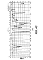
チップのための基板は、ポリマー又は他の材料であってもよい。加熱の波長は、図1によれば、(a)水の吸光度、(b)選択された光源の発光波長及び(c)基板材料の吸光度を含む範囲と重なるように選択される。例えば、各材料の吸光度スペクトルは、図中に示される。図3は、COC及びCOP(ゼオネックスTM、ゼオノアTM、トパスTM、アペルTM、アートンTMの名の下で提供)を示す。図4Aは、ポリエチレンを示す。図4Bは、ポリジメチルシロキサン(PDMS)を示す。図4Cは、ポリメチルメタクリレート(PMMA)を示す。 The substrate for the chip may be a polymer or other material. According to FIG. 1, the heating wavelength is selected to overlap a range that includes (a) the absorbance of water, (b) the emission wavelength of the selected light source, and (c) the absorbance of the substrate material. For example, the absorbance spectrum of each material is shown in the figure. FIG. 3 shows COC and COP (provided under the names ZEONEX ™ , ZEONOR ™ , TOPAS ™ , APEL ™ , ARTON ™ ). FIG. 4A shows polyethylene. FIG. 4B shows polydimethylsiloxane (PDMS). FIG. 4C shows polymethyl methacrylate (PMMA).
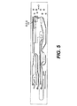
図5は、抽出、反応、保管、廃棄、反応及び分離のためのチャネルを含むチャネルと統合した例示的なマイクロ流体チップを示す。反応室は、反応室600とラベル付けされる。図6は、例示的な測定値を有する反応室600の拡大図を描く。図5及び図6は、縮尺で描かれる。反応室600は、長さ3.56mm及び幅1.21mmで体積が約1.35マイクロリットルであり、楕円形状を有する。
FIG. 5 shows an exemplary microfluidic chip integrated with channels including channels for extraction, reaction, storage, disposal, reaction and separation. The reaction chamber is labeled
図7Aは、IRレーザが覆うポリマーマイクロ装置内でIR媒介PCRを実行するポリマーPCRマイクロ流体装置700の上面図である。図7Aに示すように、マイクロデバイス700は、1つ又は複数の反応室702、1つ又は複数のIRレーザ(又はレーザ出力)704及び1つ又は複数の非接触温度センサ706を含む。IRレーザは、加熱するために使用され、コンピュータを介した非接触温度感知方法で制御される。図7Bのヒートマップに示すように、IRレーザ源は、PCRの反応室を取り囲む小さな領域を加熱する。図7Bは、赤外線カメラで撮影したヒートマップである。
FIG. 7A is a top view of a polymer PCR
従来のサーマルサイクラーを用いて得られた温度サイクルプロファイルは、図7AのIRレーザシステムを用いて増幅後に得られる温度サイクルプロファイルと比較された。マイクロ流体PCR増幅及び小さな反応容量(〜1μL)のための図7AのIRレーザシステムの使用は、総増幅時間を6倍をも短縮させる。 The temperature cycle profile obtained using a conventional thermal cycler was compared with the temperature cycle profile obtained after amplification using the IR laser system of FIG. 7A. Use of the IR laser system of FIG. 7A for microfluidic PCR amplification and small reaction volumes (˜1 μL) reduces the total amplification time by as much as 6 times.
図8(A)〜(F)は、カートリッジ/チャンバの組に指向させる異なる2つの波長を用いた熱シミュレーションの比較を示す。図8(A)〜(C)は、1720nmの波長の放射線を用いたチャンバ領域への熱の影響を示し、図8(D)〜(F)は、1930nmの波長の放射線を用いた熱の影響を示す。シミュレーションにおける温度範囲は、室温(23℃)から95℃であり、本実施形態で使用されるPCR技術の熱サイクルプロセスのピーク温度である。他の温度は、他の技術に利用することができ、本開示の教示は、本明細書で論じた温度に限定されない。 FIGS. 8A-F show a comparison of thermal simulations using two different wavelengths directed to the cartridge / chamber pair. 8 (A)-(C) show the effect of heat on the chamber region using 1720 nm wavelength radiation, and FIGS. 8 (D) -8 (F) show the thermal effects using 1930 nm wavelength radiation. Show the impact. The temperature range in the simulation is from room temperature (23 ° C.) to 95 ° C., which is the peak temperature of the thermal cycling process of the PCR technique used in this embodiment. Other temperatures can be utilized for other technologies, and the teachings of the present disclosure are not limited to the temperatures discussed herein.
シミュレーションは、10秒を超える。図8(A)及び8(D)は、1720nm及び1930nmのレーザで、それぞれが時間=0の時点である。ゼオネックスCOCにおける基板。図8(B)及び8(E)は、時間=5秒の時点である。図8(C)及び8(F)は、時間=10秒の時点である。これらの図は、液体サンプル及びチャンバ材料(1720nm)の両方を含む広い領域にわたる熱分布と、液体サンプル(1930nm)中に局在する狭い熱分布との差を示す。より広い熱分布を有するチャンバは、液体サンプル内で、非効率で且つ不完全な反応を生じさせる可能性がある温度勾配の危険性をより低くする。 The simulation exceeds 10 seconds. FIGS. 8A and 8D are 1720 nm and 1930 nm lasers, respectively, at time = 0. Substrates at ZEONEX COC. 8 (B) and 8 (E) are time points = 5 seconds. 8 (C) and 8 (F) are time points of 10 seconds. These figures show the difference between the thermal distribution over a wide area containing both the liquid sample and chamber material (1720 nm) and the narrow thermal distribution localized in the liquid sample (1930 nm). A chamber with a wider heat distribution makes the risk of temperature gradients in the liquid sample less likely to cause inefficient and incomplete reactions.
本開示によるマイクロ流体チップは、同じチップ上でPCRによる検出、抽出、PCR及び同じチップ上で分離又は抽出、PCR、分離及び検出を実行するために、チップに含まれる全てのサンプル材料と完全に統合されることができる。 The microfluidic chip according to the present disclosure is completely compatible with all sample materials contained in the chip to perform PCR detection, extraction, PCR and separation or extraction, PCR, separation and detection on the same chip. Can be integrated.
非接触加熱は、非接触温度検知と組み合わせることができる。 Non-contact heating can be combined with non-contact temperature sensing.
レーザ光源からのレーザ光は、光ファイバチャネルを介して送信されることができる。各チャネル用に別々の光源が使用されることができ、又は、単一の光源がいくつかのチャンネルソースに分割されることができる。 Laser light from a laser light source can be transmitted via an optical fiber channel. A separate light source can be used for each channel, or a single light source can be divided into several channel sources.
レーザ出力は、すべてのチャネルを均一にするために、矯正レンズを用いることができる。ここで、光ファイバレーザは、レンズを用いて調整され、このレンズは、開口数を0.22から、チップにおけるスポットサイズの直径、〜6.7mmと関連する、16.77度である光学系の先端からフルアングルまで、減少させる。 The laser output can use corrective lenses to make all channels uniform. Here, the fiber optic laser is tuned using a lens, which is an optical system that has a numerical aperture of 0.22 and is related to a spot size diameter at the chip, ˜6.7 mm, of 16.77 degrees. Decrease from the tip to the full angle.
本明細書中に記載の実施形態は、能動的な冷却を用いる又は用いないことができる。 The embodiments described herein may or may not use active cooling.
いくつかの実施形態において、レーザ源/出力は、これらの特定の要件及び設計特徴のうち1つ又は複数を有してもよい。個別にアドレス指定可能及び制御可能な4つのチャネル。10nm未満のスペクトル幅を有し、中心波長1720nm+/−10nmの波長での出力光電力。総光出力電力最小4ワットのために、各チャネルの最小電力出力1.0ワット。及び、0.20+/−0.02の開口数を有するファイバ口からの光であって、ファイバからの電力強度のプロファイルが途中で最大となり、且つ、プロファイルが略中央でほぼ一定であり、その後、最後まで一貫して減少する。 In some embodiments, the laser source / power may have one or more of these specific requirements and design features. 4 individually addressable and controllable channels. Output optical power at a wavelength of center wavelength 1720 nm +/− 10 nm with a spectral width less than 10 nm. A minimum power output of 1.0 watt for each channel for a total optical output power minimum of 4 watts. And light from a fiber port having a numerical aperture of 0.20 +/− 0.02, where the power intensity profile from the fiber is maximized on the way, and the profile is substantially constant at the center. , Consistently decreasing to the end.
チャンバは、100〜10000ナノリットルの間で様々な容積を有してもよい。
チャンバに通じるチャンネルは、様々なアーキテクチャとすることができる。
加熱速度は、広い範囲で提供することができる。
完全なハードウェアの代わりに、光ファイバケーブルを使用し、スペースを節約することができる。
The chamber may have various volumes between 100-10000 nanoliters.
The channel leading to the chamber can be of various architectures.
The heating rate can be provided in a wide range.
Instead of full hardware, fiber optic cables can be used to save space.
したがって、光を発生させるためのハードウェアは、光の出力から離れて位置することができる。熱センサ(例えば、高温計)は、故に、レーザをチャンバの同じ側に含ませることができる。これにより、完全な検出装置がよりコンパクトになり、小型化が容易になる。 Therefore, the hardware for generating light can be located away from the light output. A thermal sensor (eg, a pyrometer) can thus include a laser on the same side of the chamber. This makes the complete detection device more compact and facilitates miniaturization.
チップは、多数のチャネル及び多数の独立した反応室を有することができる。1〜20別個であるが、各チップ上にある独立の反応用に反復されたチャンネルとすることができる。独立の反応毎に複数のチャネルとすることができる。 The chip can have multiple channels and multiple independent reaction chambers. There can be 1-20 separate but repeated channels for independent reactions on each chip. There can be multiple channels for each independent reaction.
サンプル混合物は、1つ又は複数の核酸分子を含むことができ、二本鎖(ds)DNA、一本鎖(ss)DNA及びRNAから構成されるグループから選択される。 The sample mixture can include one or more nucleic acid molecules and is selected from the group consisting of double stranded (ds) DNA, single stranded (ss) DNA and RNA.
システムは、次の仕様で構成されることができる。 The system can be configured with the following specifications:
流体及び周囲に含有する材料の微小サンプルの加熱に使用するIR光源モジュールは、ポリメラーゼ連鎖反応(PCR)プロセスにおいて使用することができる。IRモジュールには、電力及び制御信号が供給される。IRモジュールには、チャネル毎に光ファイバケーブルから出力する個別にアドレス指定可能/制御可能な4つのチャンネルを備えることができる。 An IR light source module used to heat a small sample of fluid and surrounding material can be used in a polymerase chain reaction (PCR) process. The IR module is supplied with power and control signals. The IR module can include four individually addressable / controllable channels that output from the fiber optic cable for each channel.
IR光源モジュールは、制御電子機器、光源、熱管理、光学及び光ファイバ配信の組み合わせである。このモジュールは、完全なフィールド交換可能ユニット(FRU)を形成する自己完結型のユニットである。IR光源モジュールは、電力を光パワーに変換する。各チャンネルは、デジタル制御可能であり、選択的に有効/無効にして、それぞれのチャネルをアクティブ/非アクティブにすることができる。各チャネルは、アナログ又はデジタルの入力を提供されることができ、それぞれのチャネルの出力電力を制御する。 The IR light source module is a combination of control electronics, light source, thermal management, optics and fiber optic delivery. This module is a self-contained unit that forms a complete field replaceable unit (FRU). The IR light source module converts electric power into optical power. Each channel is digitally controllable and can be selectively enabled / disabled to activate / deactivate the respective channel. Each channel can be provided with an analog or digital input and controls the output power of the respective channel.
IR光源モジュールは、次の外部機能インタフェースを有することができる。電力の入力、チャンネル毎にデジタル可能、チャンネル毎に各チャンネルからの光パワーのアナログ又はデジタルによるインタフェース制御、及び、チャネル毎の光ファイバケーブルからの光パワー出力である。 The IR light source module can have the following external function interface. Input of power, digital per channel, analog or digital interface control of optical power from each channel, and optical power output from optical fiber cable for each channel.
IR光は、0.20+/−0.02の開口数を有するファイバから出力する。ファイバからの電力強度のプロファイルは、途中で最大である。プロファイルは、略中央でほぼ一定であり、その後最後まで一貫して減少してもよい。 IR light is output from a fiber having a numerical aperture of 0.20 +/− 0.02. The profile of the power intensity from the fiber is greatest on the way. The profile is approximately constant at approximately the center and may then decrease consistently to the end.
モジュールの入力電圧は、5VDC(+/−0.5V)、12VDC(+/−1.0V)又は24VDC(+/−2V)とすることができる。入力電圧は、一つ又は複数のこれらの値であってもよい。入力電圧(複数可)は、最大のユニット効率を得て、熱放散電力を最小化するように選択することができる。 The input voltage of the module can be 5 VDC (+/− 0.5 V), 12 VDC (+/− 1.0 V) or 24 VDC (+/− 2 V). The input voltage may be one or more of these values. The input voltage (s) can be selected to obtain maximum unit efficiency and minimize heat dissipation power.
光パワーを制御するためのアナログラインは、入力電圧範囲0〜5ボルトと、出力を生成しない0ボルトと5ボルトの間で線形応答をする全ての出力とを有する信号コネクタに設けられる。アナログ回線は、10kΩより大きな入力インピーダンスを有することができ、コンピュータの電圧コントローラに接続することができる。信号の帯域幅及び関連するモジュールの応答は、0kHz(DC)よりも大きく、1kHz未満である。レーザ出力(10%〜90%)の立ち上がり時間(Tr)は、帯域幅(BW)と関連し、Tr=0.35/BWの関係である。1kHzの帯域幅については、関連付けられる立ち上がり時間は350マイクロ秒である。 An analog line for controlling the optical power is provided in the signal connector having an input voltage range of 0-5 volts and all outputs having a linear response between 0 and 5 volts that do not produce an output. The analog line can have an input impedance greater than 10 kΩ and can be connected to a computer voltage controller. The signal bandwidth and associated module response is greater than 0 kHz (DC) and less than 1 kHz. The rise time (Tr) of the laser output (10% to 90%) is related to the bandwidth (BW) and is Tr = 0.35 / BW. For a 1 kHz bandwidth, the associated rise time is 350 microseconds.
モジュールからのIR光は、公称直径200um及び開口数(NA)0.22を有する光ファイバケーブルに結合する。光ファイバケーブルは、モジュールの外側に外部バルクヘッドコネクタを有するモジュールから着脱可能である。レーザモジュールコネクタは、SMA905コネクタを受け付ける。モデルの出力電力は、ケーブルの出力で測定される。 IR light from the module is coupled to a fiber optic cable having a nominal diameter of 200 um and a numerical aperture (NA) of 0.22. The fiber optic cable is detachable from the module having an external bulkhead connector on the outside of the module. The laser module connector accepts an SMA 905 connector. The model output power is measured at the output of the cable.
レーザの出射は、反応室から約21mmに配置され、光ファイバレーザは、レンズを用いて調整され、このレンズは、開口数を0.22から、チップでのスポットサイズ直径〜6.7mmに関連する、16.77度である光学系の先端からフルアングルまで、減少させる。 The laser emission is located approximately 21 mm from the reaction chamber, and the fiber optic laser is tuned using a lens that is associated with a numerical aperture of 0.22 and a spot size diameter at the tip of ~ 6.7 mm. Reduce from the tip of the optical system at 16.77 degrees to the full angle.
1720nm(赤外線レーザ光線経路)での光出力は、以下(i)〜(iii)から構成される。(i)レーザハウジングが存在し、即時に(ii)光ファイバと結合され、光ファイバは、(iii)レンズアセンブリ(開口数0.22を有する)と接続し、レンズアセンブリは、レーザビームを拡大する。レンズアセンブリは、垂直に取り付けられるので、出射するレーザは、チップを保持するモジュールのカバープレート近くの上方に向けられる。チップは、レーザ経路がチップ及び/又は反応室の表面に対して垂直となるように比較的、水平に取り付けることができる。また、レーザ経路は、垂線に対する角度で提供することができる。温度検出経路は、垂線に対する角度で提供することができ、レーザ経路と干渉しないように提供することができる。 The light output at 1720 nm (infrared laser beam path) is composed of (i) to (iii) below. (I) a laser housing is present and immediately (ii) coupled with an optical fiber, the optical fiber connects to (iii) a lens assembly (having a numerical aperture of 0.22), and the lens assembly expands the laser beam To do. Since the lens assembly is mounted vertically, the emitting laser is directed upward near the cover plate of the module holding the chip. The tip can be mounted relatively horizontally such that the laser path is perpendicular to the tip and / or reaction chamber surface. The laser path can also be provided at an angle to the normal. The temperature sensing path can be provided at an angle to the normal and can be provided so as not to interfere with the laser path.
例示的なレーザ操作手順/アルゴリズム制御
レーザの起動手順: システムがオンになると、レーザに電力が供給される。コンピュータを介したソフトウェア・インタフェースによりコマンド信号が送信されたときのみ、レーザ出射は起こる。
Exemplary Laser Operating Procedure / Algorithm Control Laser Startup Procedure: When the system is turned on, power is supplied to the laser. Laser emission occurs only when a command signal is transmitted by a software interface via a computer.
PCR手順: ソフトウェア・インタフェースを操作するに先立ち、チップは、カバー付きホルダーの所定の位置に配置されるべきである。そのときになって初めて、レーザに制御信号を送信するソフトウェアが使用されるべきである。温度感知(例えば、高温計)フィードバック信号は、ソフトウェア・インタフェースを介してレーザが動作中であり、且つ、PCR手順が動作中の間はそのカバーが除去されるべきではないことを示すことができる。 PCR procedure: Prior to operating the software interface, the chip should be placed in place on the covered holder. Only then should software to send control signals to the laser should be used. A temperature sensing (eg, pyrometer) feedback signal can indicate via a software interface that the laser is operating and that the cover should not be removed while the PCR procedure is operating.
レーザシャットダウン手順: 前カバーを取り外す前にレーザがオフになっていることを確実にするために、ソフトウェアでは手動操作モードが選択でき、ゼロ出力電圧をそこに入力することができる。ソフトウェアを介して適切なコマンドを実行することにより、レーザ出力をオフにすることができる。この手順は、各レーザについて繰り返すことができ、温度測定は、レーザがいかなる放射線を出力していないことを確認するために観察することができる。また、電源供給を切断すると、レーザへの電源がオフになる。 Laser Shutdown Procedure: To ensure that the laser is turned off before removing the front cover, the software allows the manual operation mode to be selected and a zero output voltage can be input there. The laser output can be turned off by executing the appropriate command via software. This procedure can be repeated for each laser, and temperature measurements can be observed to confirm that the laser is not outputting any radiation. When the power supply is cut off, the power to the laser is turned off.
例示的なDNAの準備
口腔スワブは、ドナーから得られ、且つ、ZYGEMTM緩衝液98マイクロリットル及びPREPGEMTM酵素2マイクロリットルが加えられた。得られたサンプルは、従来のサーマルサイクラーにおいて、75℃で2分間及び95℃で2分間、培養された。
Exemplary DNA preparation Oral swabs were obtained from a donor and 98 microliters of ZYGEM ™ buffer and 2 microliters of PREPGEM ™ enzyme were added. The resulting sample was incubated for 2 minutes at 75 ° C. and 2 minutes at 95 ° C. in a conventional thermal cycler.
POWERPLEX(登録商標)18: DNAは、総容積10マイクロリットルのために、POWERPLEX(登録商標)マスターミックス2マイクロリットル及びPOWERPLEX(登録商標)プライマー1マイクロリットルが加えられた。 POWERPLEX® 18: DNA was added to 2 microliters of POWERPLEX® master mix and 1 microliter of POWERPLEX® primer for a total volume of 10 microliters.
IDENTIFILERTM: DNAは、総容積10マイクロリットルのために、PYROSTARTTMマスターミックス(Fermentas社TM)5マイクロリットル、IDENTIFILERTMプライマー(APPLIED BIOSYSTEMSから)2.25マイクロリットル、SPEEDSTARTMDNAポリメラーゼ(タカラバイオから)0.25マイクロリットル及び10mg/mL BSA0.5マイクロリットルに加えられた。 IDENTIFILER ™ : DNA is 5 microliters of PYROSTART ™ master mix (Fermentas ™ TM ), IDENTIFILER ™ primer (from APPLIED BIOSSYSTEMS), 2.25 microliters, SPEEDSTAR ™ DNA polymerase (from Takara Bio) for a total volume of 10 microliters ) 0.25 microliter and 10 mg / mL BSA 0.5 microliter.
例示的な熱サイクル手順/アルゴリズムの制御 Example thermal cycle procedure / algorithm control
PROMEGAPOWERPLEX(登録商標):96℃で1分間、(94℃で5秒間、60℃で10秒間、72℃で10秒間を)30サイクル、且つ、最後に60℃で60秒間。温度は、受動的又は能動的な冷却と併せて、コンピュータによる制御された加熱及びアルゴリズム処理により維持される。 PROMEGAPOWERPLEX®: 96 cycles for 1 minute at 96 ° C., 30 cycles (94 ° C. for 5 seconds, 60 ° C. for 10 seconds, 72 ° C. for 10 seconds), and finally 60 ° C. for 60 seconds. The temperature is maintained by computer controlled heating and algorithmic processing in conjunction with passive or active cooling.
INDENTIFILERTM:95℃で1分間、(95℃で5秒間、59℃で10秒間、72℃で10秒間を)32サイクル、且つ、最後に60℃で60秒間。温度は、受動的又は能動的な冷却と併せて、コンピュータによる制御された加熱及びアルゴリズム処理により維持される。 INDIFIFILER ™ : 95 cycles for 1 minute, 95 ° C for 5 seconds, 59 ° C for 10 seconds, 72 ° C for 10 seconds) and finally 60 ° C for 60 seconds. The temperature is maintained by computer controlled heating and algorithmic processing in conjunction with passive or active cooling.
例示的な統合型チップサーマルサイクリング手順/制御アルゴリズム Exemplary integrated chip thermal cycling procedure / control algorithm
LIFE TECHNOLOGIES IDENTIFIERTMを使用して、サンプルは、初期の変性工程のために、最初の温度95℃で60秒間保持された。次に、(a)IRレーザで95℃に加熱され、5秒間保持され、(b)ソースがオフになり、2.1°C/秒で60℃に受動的に冷却し、10秒間保持され、且つ、(c)次いで、3.7℃/秒の速度で72℃まで加熱し、10秒間保持され、これらが26サイクル行われた。その後、最終延長が5分間あった。増幅の結果は、電気泳動によりチップ上で分離した。 Using LIFE TECHNOLOGIES IDENTIFIER ™ , samples were held for 60 seconds at an initial temperature of 95 ° C for the initial denaturation step. Next, (a) heated to 95 ° C. with IR laser and held for 5 seconds, (b) source turned off, passively cooled to 60 ° C. at 2.1 ° C./second and held for 10 seconds And (c) then heated to 72 ° C. at a rate of 3.7 ° C./second and held for 10 seconds, which were performed 26 cycles. Thereafter, there was a final extension of 5 minutes. The amplification results were separated on the chip by electrophoresis.
PROMEGA POWERPLEX18DTMを使用して、サンプルは、初期の変性工程のために、最初の温度95℃で60秒間保持された。次に、(a)IRレーザで95℃に加熱され、5秒間保持され、(b)ソースがオフになり、2.1°C/秒で60℃に受動的に冷却し、10秒間保持され、且つ、(c)次いで、3.7℃/秒の速度で72℃まで加熱し、10秒間保持され、これらが27サイクル行われた。その後、最終延長が5分間あった。増幅の結果は、電気泳動によりチップ上で分離した。 Using the PROMEGA POWERPLEX 18D ™ , the sample was held at an initial temperature of 95 ° C. for 60 seconds for the initial denaturation step. Next, (a) heated to 95 ° C. with IR laser and held for 5 seconds, (b) source turned off, passively cooled to 60 ° C. at 2.1 ° C./second and held for 10 seconds And (c) then heated to 72 ° C. at a rate of 3.7 ° C./second and held for 10 seconds, these being performed 27 cycles. Thereafter, there was a final extension of 5 minutes. The amplification results were separated on the chip by electrophoresis.
別の実施形態では、LIFE TECHNOLOGIES IDENTIFIERTMを使用して、サンプルは、初期の変性工程のために、最初の温度94℃で60秒間保持された。次に、(a)IRレーザで94℃に加熱され、5秒間保持され、(b)ソースがオフになり、2.1°C/秒で59℃に受動的に冷却し、20秒間保持され、これらが27サイクル行われた。次いで、72℃で5分間の最終延長があった。増幅の結果は、電気泳動によりチップ上で分離した。 In another embodiment, using LIFE TECHNOLOGIES IDENTIFIER ™ , the sample was held at an initial temperature of 94 ° C for 60 seconds for an initial denaturation step. Next, (a) heated to 94 ° C. with IR laser and held for 5 seconds, (b) source turned off, passively cooled to 59 ° C. at 2.1 ° C./s and held for 20 seconds These were performed 27 cycles. There was then a final extension of 5 minutes at 72 ° C. The amplification results were separated on the chip by electrophoresis.
PROMEGA POWERPLEX18DTMを使用して、サンプルは、初期の変性工程のために、最初の温度94℃で60秒間保持された。次に、(a)IRレーザで94℃に加熱され、10秒間保持され、(b)ソースがオフになり、2.1°C/秒で59℃に受動的に冷却し、40秒間保持され、これらが27サイクル行われた。次いで、60℃で5分間の最終延長があった。増幅の結果は、電気泳動によりチップ上で分離した。 Using the PROMEGA POWERPLEX 18D ™ , the sample was held at an initial temperature of 94 ° C. for 60 seconds for the initial denaturation step. Next, (a) heated to 94 ° C. with IR laser and held for 10 seconds, (b) source turned off, passively cooled to 59 ° C. at 2.1 ° C./s and held for 40 seconds These were performed 27 cycles. There was then a final extension of 5 minutes at 60 ° C. The amplification results were separated on the chip by electrophoresis.
しかし、他の時間及び温度は、本開示の教示に従って利用することができ、上述の値は、対応する時間の近似値が所定の範囲内に収まる近似値又は平均値とすることができる。 However, other times and temperatures can be utilized in accordance with the teachings of the present disclosure, and the above-described values can be approximate values or average values where the corresponding approximate time values fall within a predetermined range.
図9は、本開示による例示的なアルゴリズムプロセス900を示すフローチャートである。ステップS902では、パラメータは、プロセスを制御するために、システム、処理システム又はコンピュータに入力される。例示的なパラメータは、反応室の材料、熱源(複数可)の種類、冷却源(複数可)の種類、温度感知装置(複数可)の種類、反応室内の流体の量、反応室内の主要な構成要素、温度、保持時間、サイクル数及び動作モードを含む。動作モードは、自動、半自動又は手動に設定することができ、全プロセスを通して相互作用の異なるレベルをユーザに提供する。周辺機器及びディスプレイを介してコンピュータのGUI(グラフィカルユーザインタフェース)により入力することができる。パラメータのリストは、網羅的ではない。パラメータは、コンピュータのデータファイルに事前に定義され、且つ、1つ又はいくつかのオプションを単に選択することでアクセスすることができる。また、テーブルデータファイルは、事前に定義された手順の設定を選択するために使用することができる。また、コンピュータは、期待される熱源、受動的冷却及び期待される温度感知装置をデフォルトに設定することができる。さらに、デフォルトは、予め設定された温度、保持時間、温度変化の速度及びサイクル数を含むことができる。
FIG. 9 is a flowchart illustrating an
パラメータがコンピュータに入力され、選択され及び読み込まれ、又は、そうでなければステップS902の処理システムで定義され、且つ、機器(すなわち、マイクロ流体チップ、ホルダー、熱源、冷却源及び温度センサ)及び流体が適切に確立され、変性ステップがステップS904で提供されることができる。ステップS904における変性ステップは、初期の時間に初期の変性温度で流体サンプルを保持することを含む。 Parameters are entered into the computer, selected and read, or otherwise defined in the processing system of step S902, and equipment (ie, microfluidic chip, holder, heat source, cooling source and temperature sensor) and fluid Is properly established and a denaturation step can be provided in step S904. The denaturing step in step S904 includes holding the fluid sample at an initial denaturing temperature at an initial time.
ステップS904の変性ステップの後、サンプル、流体及び/又は反応室の加熱(本明細書中で単に加熱と称する)は、ステップS906で開始する。ステップS906で、加熱は、第1加熱速度で実行され、所定の第1加熱速度に到達するために、第1温度に到達するまで、熱源を介して加熱量が印加される。別の実施形態では、加熱速度(すなわち、第1速度)が定義されなくてもよい。第1温度は、ステップS908で第1時間保持される。 After the denaturation step of step S904, heating of the sample, fluid and / or reaction chamber (referred to herein simply as heating) begins at step S906. In step S906, heating is performed at a first heating rate, and a heating amount is applied through a heat source until the first temperature is reached in order to reach a predetermined first heating rate. In another embodiment, the heating rate (ie, the first rate) may not be defined. The first temperature is held for a first time in step S908.
サンプル、流体及び/又は反応室(本明細書中で単に冷却と称する)の冷却は、ステップS910で、受動的又は能動的のいずれか、第2の速度で又は少なくとも第2の速度(すなわち、第2冷却速度)で第2温度まで実行される。別の実施形態では、第2冷却速度(すなわち、第2速度)は、定義されなくてもよい。第2温度は、ステップS912で、第2時間保持される。 Cooling of the sample, fluid and / or reaction chamber (referred to herein simply as cooling) is performed at step S910, either passively or actively, at a second rate or at least a second rate (ie, The second cooling rate is performed up to the second temperature. In another embodiment, the second cooling rate (ie, the second rate) may not be defined. The second temperature is held for a second time in step S912.
ステップS914で、加熱は、第3加熱速度で実行され、所定の第3加熱速度に到達するために、第3温度に到達するまで、熱源を介して加熱量が印加される。別の実施形態では、第3加熱速度(すなわち、第3速度)が定義されなくてもよい。第3温度は、ステップS916で第3時間保持される。 In step S914, the heating is performed at the third heating rate, and a heating amount is applied through the heat source until the third temperature is reached in order to reach a predetermined third heating rate. In another embodiment, the third heating rate (ie, the third rate) may not be defined. The third temperature is held for a third time in step S916.
ステップS906〜S916の手順は、1周期を定義する。パラメータ(すなわち、加熱/冷却変数)は、自動モードが選択されている場合の所定の入力に基づいて、又は、半自動モードが選択されている場合のユーザ入力に基づいて、各サイクルの後にステップS918で選択的に調整することができる。手動モードで、ユーザは、各ステップ/手順を制御し、コンピュータは、ユーザ入力が受信されるまで、1つ又は複数のアルゴリズムの態様に進まない。 The procedure of steps S906 to S916 defines one cycle. The parameter (ie, heating / cooling variable) is determined after step S918 based on a predetermined input when the automatic mode is selected or based on a user input when the semi-automatic mode is selected. Can be selectively adjusted. In manual mode, the user controls each step / procedure and the computer does not proceed to one or more algorithmic aspects until user input is received.
ステップS920では、サイクル数に到達するまで、ステップS906〜S916又はステップS906〜S918が複数回繰り返される。この数は、予め定義され又はリアルタイムでユーザにより選択されることができる。また、この数は、サンプルの観察可能な又は検出可能な特性に関連するセンサ入力に基づいて、自動的に、コンピュータにより選択されることができる。 In step S920, steps S906 to S916 or steps S906 to S918 are repeated a plurality of times until the number of cycles is reached. This number is predefined or can be selected by the user in real time. This number can also be automatically selected by a computer based on sensor inputs related to the observable or detectable characteristics of the sample.
サイクルが完了した後、第3温度は、ステップS922で最終延長時間保持され、且つ、S924で電気泳動が実行される。 After the cycle is complete, the third temperature is held for a final extension time in step S922, and electrophoresis is performed in S924.
上記のアルゴリズムでは、加熱及び冷却速度は、定期的に処理温度の測定値によりモニタされることができ、且つ、熱源による加熱量及び能動的な冷却装置により提供される冷却量を調整することで制御することができる。特定の加熱/冷却設定が原因で、ある加熱/冷却速度に到達することが知られている場合には、加熱/冷却速度をモニタすることは必要ではないかもしれない。さらに、加熱/冷却速度は、ある閾値を超えていることを単に確認するためにモニタしてもよい。 In the above algorithm, the heating and cooling rates can be monitored periodically by process temperature measurements and by adjusting the amount of heating by the heat source and the amount of cooling provided by the active cooling device. Can be controlled. If it is known to reach a certain heating / cooling rate due to a particular heating / cooling setting, it may not be necessary to monitor the heating / cooling rate. Furthermore, the heating / cooling rate may be monitored to simply confirm that a certain threshold is exceeded.
先に論じた例示的な実施形態によれば、以下の設定を適用することができる。 According to the exemplary embodiment discussed above, the following settings can be applied.
サンプル/流体 容量: 10ミリリットル
変性: 95°Cで60秒間。
サイクル数: 27。
第1温度: 95°C。
第1保持時間: 5秒間。
第1速度:> 3℃/秒(正、加熱)。
第2温度: 60°C。
第2保持時間: 10秒間。
第2速度: 2.1℃/秒(負、冷却)。
第3温度: 72℃。
第3保持時間: 10秒間。
第3速度: 3.7℃/秒(正、加熱)。且つ
最終延長時間: 5分間。
Sample / fluid Volume: 10 ml Denaturation: 95 ° C. for 60 seconds.
Number of cycles: 27.
First temperature: 95 ° C.
First holding time: 5 seconds.
First rate:> 3 ° C./s (positive, heating).
Second temperature: 60 ° C.
Second holding time: 10 seconds.
Second speed: 2.1 ° C./second (negative, cooling).
Third temperature: 72 ° C.
Third retention time: 10 seconds.
Third speed: 3.7 ° C./s (positive, heating). And final extension time: 5 minutes.
別の例示的な実施形態によれば、以下の設定を適用することができる。
サンプル/流体 容量: <10ミリリットル
変性: 50〜96°Cで60秒間。
サイクル数: 20〜35。
第1温度: 50〜95°C。
第1保持時間: 2〜10秒間。
第1速度:> 3℃/秒(正、加熱)。
第2温度: 50〜96°C。
第2保持時間: 5〜20秒間。
第2速度: 2℃/秒(負、冷却)。
第3温度: 50〜96℃。
第3保持時間: 5〜20秒間。
第3速度: 3℃/秒(正、加熱)。且つ
最終延長時間: 2〜15分間。
According to another exemplary embodiment, the following settings can be applied.
Sample / fluid Volume: <10 ml Denaturation: 50-96 ° C. for 60 seconds.
Number of cycles: 20-35.
1st temperature: 50-95 degreeC.
First holding time: 2 to 10 seconds.
First rate:> 3 ° C./s (positive, heating).
Second temperature: 50-96 ° C.
Second holding time: 5 to 20 seconds.
Second rate: 2 ° C./second (negative, cooling).
Third temperature: 50-96 ° C.
Third retention time: 5 to 20 seconds.
Third speed: 3 ° C./second (positive, heating). And final extension time: 2-15 minutes.
本明細書で示した又は説明したコンピュータアーキテクチャの複数のブロックは、単一の処理システムで実施されてもよく、又は、プロセッサと称される可能性のある複数の処理システムに渡って分散されてもよい。例えば、各アーキテクチャのブロックは、別個のプロセッサ、システム又は論理コンポーネントとすることができる。 Multiple blocks of the computer architecture shown or described herein may be implemented in a single processing system or distributed across multiple processing systems, which may be referred to as processors. Also good. For example, each architectural block may be a separate processor, system or logical component.
図10は、例示的な処理システム又はプロセッサ1000を示す。1つ又は複数のこのような処理システムは、本明細書の記載に従って、1つ若しくは複数のアルゴリズム又はこれらの一部、又は、1つ若しくは複数のアーキテクチャのブロック又はこれらの一部を実行して又はが使用されることができる。
FIG. 10 shows an exemplary processing system or
例示的な処理システム1000は、1つ又は複数のマイクロプロセッサ又は同等物を使用して実装されることができる。例えば、中央処理装置(CPU)及び/又は少なくとも1つのアプリケーション特化型プロセッサASP(図示せず)がある。マイクロプロセッサは、コンピュータ可読記憶媒体を使用する回路であって、本開示のプロセス及びシステムを実行及び/又は制御するためのマイクロプロセッサを制御するように構成される。例えば、メモリ回路(例、ROM、EPROM、EEPROM、フラッシュメモリ、スタティックメモリ、DRAM、SDRAM、及びその等価物)がある。他の記憶媒体は、ハードディスクドライブ又は光ディスクドライブを制御するコントローラを介して制御することができる。例えば、ディスクコントローラがある。
The
マイクロプロセッサ又はこの態様は、代替の実施形態で、本開示を増大する又は完全に実施するための論理デバイスを含み又は排他的に含むことができる。このような論理装置は、特定用途向け集積回路(ASIC)、フィールドプログラマブルゲートアレイ(FPGA)、汎用配列ロジック(GAL)及びそれらの等価物を含むが、これらに限定されない。マイクロプロセッサは、別の装置又は単一の処理機構とすることができる。さらに、本開示は、マルチコアCPUの並列処理能力により利益を享受する。また、マルチプロセッサの配列で1つ又は複数のプロセッサにより提供される制御回路は、メモリに含まれる一連の命令を実行するために採用されることができる。代替的に、ハードワイヤード回路は、ソフトウェア命令に代わって又はソフトウェア命令と組み合わせて使用することができる。このように、本明細書で論じる例示的な実装は、ハードウェア回路及びソフトウェアの特定の組み合わせに限定されるものではない。 The microprocessor or this aspect may, in alternative embodiments, include or exclusively include logic devices to augment or fully implement the present disclosure. Such logic devices include, but are not limited to, application specific integrated circuits (ASICs), field programmable gate arrays (FPGAs), general purpose array logic (GAL) and their equivalents. The microprocessor can be a separate device or a single processing mechanism. Furthermore, the present disclosure benefits from the parallel processing capabilities of multi-core CPUs. Also, control circuitry provided by one or more processors in a multiprocessor arrangement can be employed to execute a series of instructions contained in a memory. Alternatively, hardwired circuitry can be used in place of or in combination with software instructions. As such, the example implementations discussed herein are not limited to any specific combination of hardware circuitry and software.
別の態様では、本開示に従った処理の結果は、表示制御部を介してモニタに表示することができる。表示制御部は、好ましくは、少なくとも1つのグラフィックス処理ユニットを含み、計算効率の改善のために、複数のグラフィックス処理コアにより提供されることができる。追加的に、I/O(入力/出力)インタフェースは、周辺機器としてI/Oインタフェースに接続可能なマイク、スピーカー、カメラ、マウス、キーボード、タッチベースのディスプレイ又はパッドインターフェース等からの信号及び/又はデータを入力するために設けられる。例えば、本開示の様々なプロセス又はアルゴリズムのパラメータを制御するためのキーボード及びポインティングデバイスは、追加の機能及び構成オプション又は制御表示特性を提供するために、I/Oインタフェースに接続することができる。さらに、モニタは、コマンド/命令インタフェースを提供するためのタッチセンサ式インタフェースを備えることができる。 In another aspect, the results of the processing according to the present disclosure can be displayed on a monitor via the display controller. The display controller preferably includes at least one graphics processing unit and can be provided by multiple graphics processing cores for improved computational efficiency. Additionally, the I / O (input / output) interface may be a signal and / or from a microphone, speaker, camera, mouse, keyboard, touch-based display or pad interface, etc. that can be connected to the I / O interface as a peripheral device. It is provided for inputting data. For example, keyboards and pointing devices for controlling parameters of various processes or algorithms of the present disclosure can be connected to the I / O interface to provide additional functionality and configuration options or control display characteristics. In addition, the monitor can include a touch sensitive interface to provide a command / instruction interface.
また、I/Oインタフェースは、冷却源(複数可)、熱源(複数可)及び温度センサに接続される。 The I / O interface is connected to the cooling source (s), the heat source (s) and the temperature sensor.
上記コンポーネントは、制御可能なパラメータを含むデータの送信又は受信をするネットワークインターフェースを介してネットワーク、例えば、インターネット又はローカルのイントラネットに接続することができる。セントラルバスは、上記ハードウェアコンポーネント同士を接続するために設けられ、且つ、これらの間のデジタル通信のために少なくとも一つの経路を提供する。 The component can be connected to a network, such as the Internet or a local intranet, via a network interface that transmits or receives data including controllable parameters. A central bus is provided to connect the hardware components together and provides at least one path for digital communication between them.
適切なソフトウェア、例えば、オペレーティングシステム又はアプリケーションは、メモリ及び記憶装置を含む処理システムのコンピュータ可読媒体に有形的に格納することができる。コンピュータ可読媒体の他の例は、コンパクトディスク、ハードディスク、フロッピーディスク、テープ、磁気光学ディスク、PROM(EPROM、EEPROM、フラッシュEPROM)、DRAM、SRAM、SDRAM又は他のいかなる磁気媒体、コンパクトディスク(例えば、CD−ROM)又はコンピュータが読取可能な他のいかなる媒体を含む。ソフトウェアは、デバイスドライバ、オペレーティングシステム、開発ツール、アプリケーションソフトウェア及び/又はGUIを含んでもよいが、これらに限定されない。 Appropriate software, such as an operating system or application, can be tangibly stored on a computer-readable medium of a processing system including memory and storage devices. Other examples of computer readable media include compact disk, hard disk, floppy disk, tape, magneto-optical disk, PROM (EPROM, EEPROM, flash EPROM), DRAM, SRAM, SDRAM or any other magnetic medium, compact disk (eg, CD-ROM) or any other computer readable medium. The software may include, but is not limited to, device drivers, operating systems, development tools, application software, and / or GUI.
上記記載の媒体上のコンピュータコード要素は、解釈可能又は実行可能な任意のコードメカニズムであってもよく、スクリプト、解釈可能なプログラム、ダイナミックリンクライブラリ(DLL)、Javaクラス及び完全に実行可能なプログラムを含むが、これらに限定されない。また、本開示の態様の処理の一部は、より良い性能、信頼性及び/又はコストのために分散されてもよい。 The computer code elements on the media described above may be any interpretable or executable code mechanism, such as scripts, interpretable programs, dynamic link libraries (DLLs), Java classes, and fully executable programs. Including, but not limited to. Also, some of the processing of aspects of the present disclosure may be distributed for better performance, reliability, and / or cost.
本明細書に記載された手順及びルーチンは、システム、方法又はコンピュータプログラム製品として具現化することができ、1つ又は複数の専用の回路又はプログラムされたプロセッサを介して実行することができる。したがって、本明細書で提供される説明は、専用ハードウェアの形態、ハードウェアで実行される専用ソフトウェアの形態(ファームウェア、常駐ソフトウェア、マイクロコード等を含む)又は専用のハードウェアコンポーネント及び特定のアルゴリズムと処理コードで構成される汎用プロセッサの組合せによる形態をとってもよい。ハードウェアコンポーネントは、「回路」、「モジュール」、「ユニット」、「装置」又は「システム」と称される。ハードウェアにより実行される実行可能なコードは、コンピュータプログラム製品のように有形のメモリ装置上で具現化される。例としては、CD、DVD、フラッシュドライブ、ハードディスクユニット、ROM、RAM及び他のメモリ装置を含む。 The procedures and routines described herein may be embodied as a system, method or computer program product and may be executed via one or more dedicated circuits or programmed processors. Accordingly, the description provided herein is in the form of dedicated hardware, dedicated software executed on hardware (including firmware, resident software, microcode, etc.) or dedicated hardware components and specific algorithms. And a general-purpose processor composed of processing codes. A hardware component is referred to as a “circuit”, “module”, “unit”, “device”, or “system”. Executable code executed by hardware is embodied on a tangible memory device, such as a computer program product. Examples include CD, DVD, flash drive, hard disk unit, ROM, RAM and other memory devices.
参照は、本開示の実施形態による方法、システム及びコンピュータプログラム製品のフローチャート図及びブロック図においてなされる。これらの態様は、コンピュータプログラム命令により実行される。これらのコンピュータプログラム命令は、マシンを生成するために汎用コンピュータ、専用コンピュータ、又は他のプログラム可能データ処理装置のプロセッサに提供されてもよい。例えば、コンピュータ又は他のプログラム可能データ処理装置のプロセッサを介して実行され、フローチャート及び/又はブロック図のブロック又は複数のブロックで特定された機能/動作を実施するための手段を作成する命令がある。 Reference is made to flowchart diagrams and block diagrams of methods, systems and computer program products according to embodiments of the present disclosure. These aspects are performed by computer program instructions. These computer program instructions may be provided to the processor of a general purpose computer, special purpose computer, or other programmable data processing device to generate a machine. For example, instructions may be executed through a processor of a computer or other programmable data processing device to create a means for performing the function / operation identified in the block and / or block diagram of the flowchart and / or block diagram. .
また、これらのコンピュータプログラム命令は、コンピュータ可読媒体に格納することができ、コンピュータ又は他のプログラム可能データ処理装置に、特定の方法で機能するように指示を出すことができる。例えば、コンピュータ可読媒体に格納された命令は、フローチャート及び/又はブロック図のブロック又は複数のブロックで特定された機能/動作を実行するための命令手段を含む作成項目を生成する。 These computer program instructions can also be stored on a computer readable medium and can instruct a computer or other programmable data processing device to function in a particular manner. For example, instructions stored on a computer readable medium generate a creation item that includes instruction means for performing the function / operation identified in the block or blocks of the flowchart and / or block diagram.
また、コンピュータプログラム命令は、コンピュータ実行プロセスを生成するコンピュータ又は他のプログラム可能装置で一連の動作ステップを実行させるために、コンピュータ又は他のプログラム可能データ処理装置に読み込まれてもよい。例えば、コンピュータ又は他のプログラム可能装置で実行される命令は、フローチャート及び/又はブロック図のブロック又は複数のブロックで特定された機能/動作を実現するためのプロセスを提供する。 Computer program instructions may also be read into a computer or other programmable data processing device to cause a series of operational steps to be performed on a computer or other programmable device that generates a computer-executed process. For example, instructions executed on a computer or other programmable device provide a process for implementing the functions / operations identified in the block or blocks of the flowcharts and / or block diagrams.
多くの実施形態が記載されてきた。上記に関わらず、本開示の精神及び範囲から逸脱することなくなされた種々の改変は、理解される。例えば、開示技術のステップが異なる順序で実行された場合、開示システムの構成要素が異なる方法で組み合わされた場合、又は、構成要素が他の構成要素により置き換えられ又は補充された場合、好適な結果が達成されてもよい。本明細書に記載された機能、プロセス及びアルゴリズムは、本明細書に記載された機能、プロセス及びアルゴリズムを実行するためのプログラムコード及び/又はコンピュータ命令を実行するように構成されたコンピュータプロセッサ及び/又はプログラム可能回路を含むハードウェアで実施され、又は、これらを含むハードウェアにより実行されるソフトウェアで実施されてもよい。追加的に、いくつかの実施形態は、これらに記載されたものと同一ではないモジュール又はハードウェア上で実施されてもよい。結果的に、他の実施形態は、主張した特許請求の範囲内にあってもよい。 A number of embodiments have been described. Notwithstanding the foregoing, various modifications made without departing from the spirit and scope of the disclosure will be appreciated. For example, good results if the steps of the disclosed technology are performed in a different order, if the components of the disclosed system are combined in different ways, or if the components are replaced or supplemented by other components May be achieved. The functions, processes, and algorithms described herein may be computer processors configured to execute program code and / or computer instructions for performing the functions, processes, and algorithms described herein. Alternatively, it may be implemented in hardware including a programmable circuit, or may be implemented in software executed by hardware including these. In addition, some embodiments may be implemented on modules or hardware that are not identical to those described. Consequently, other embodiments may be within the scope of the claimed claims.
Claims (20)
前記反応室及び前記流体を加熱する非接触熱源であって、前記熱源は、前記反応室又は前記流体と接触せず、且つ、前記反応室及び前記流体は、前記熱源からの熱放射を別々に吸収する、非接触熱源と、
前記反応室及び/又は前記流体の温度を取得する温度センサと、
前記反応室の加熱及び非加熱の間で前記熱源をサイクルする流体と、前記温度センサにより取得された前記温度に基づく流体と、における化学又は生化学反応のために、サイクリングプロファイルに従って前記熱源を制御するように構成された制御回路と、
を具備する装置。 A reaction chamber containing fluid,
A non-contact heat source for heating the reaction chamber and the fluid, wherein the heat source is not in contact with the reaction chamber or the fluid, and the reaction chamber and the fluid separately emit heat radiation from the heat source; A non-contact heat source to absorb,
A temperature sensor for obtaining the temperature of the reaction chamber and / or the fluid;
Control the heat source according to a cycling profile for chemical or biochemical reactions in the fluid that cycles the heat source between heating and non-heating of the reaction chamber and the temperature-based fluid acquired by the temperature sensor A control circuit configured to:
A device comprising:
前記熱源は、前記反応室毎に非接触熱の出力を含み、
前記温度センサは、前記反応室毎に個別の温度を取得し、且つ、
前記制御回路は、前記温度センサ及び前記サイクリングプロファイルにより取得された各々の温度に基づいて、前記反応室毎に独立して前記熱源を制御する、装置。 The apparatus of claim 2, comprising:
The heat source includes an output of non-contact heat for each reaction chamber,
The temperature sensor acquires an individual temperature for each reaction chamber; and
The said control circuit is an apparatus which controls the said heat source independently for every said reaction chamber based on each temperature acquired by the said temperature sensor and the said cycling profile.
(a) 第1速度で第1温度まで加熱すること、
(b) 前記第1温度を第1保持時間保持すること、
(c) 第2速度で第2温度まで冷却すること、
(d) 前記第2温度を第2保持時間保持すること、
(e) 第3速度で第3温度まで加熱すること、且つ、
(f) 前記第3温度を第3保持時間保持すること、
を含む、装置。 The apparatus according to claim 1, wherein the cycling profile comprises the following step (a) heating to a first temperature at a first rate:
(B) holding the first temperature for a first holding time;
(C) cooling to a second temperature at a second speed;
(D) holding the second temperature for a second holding time;
(E) heating to a third temperature at a third rate; and
(F) holding the third temperature for a third holding time;
Including the device.
前記流体の量<10ml
前記所定のサイクル数=20〜35
前記第1温度=50〜96℃
前記第1保持時間=2〜20秒
前記第1速度=>−2℃/s
前記第2温度=50〜96℃
前記第2保持時間=5〜60秒
前記第2速度<−1℃/s
前記第3温度=50〜96℃
前記第3保持時間=5〜60秒
前記第3速度=>2℃/s、且つ、
前記最終延長時間=1〜15分
を満たすようなサイクリングプロファイルに従って前記熱源を制御するように構成される、装置。 13. The apparatus according to claim 12, wherein the control circuit has the following condition: the amount of fluid < 10 ml.
The predetermined number of cycles = 20 to 35
The first temperature = 50 to 96 ° C.
The first holding time = 2 to 20 seconds The first speed => − 2 ° C./s
The second temperature = 50 to 96 ° C.
The second holding time = 5 to 60 seconds The second speed <−1 ° C./s
The third temperature = 50 to 96 ° C.
The third holding time = 5 to 60 seconds, the third speed => 2 ° C./s, and
An apparatus configured to control the heat source according to a cycling profile that satisfies the final extension time = 1-15 minutes.
変性温度=50〜96℃、且つ、
変性時間は、60秒と等しい又は60秒以上である、
を満たすようなサイクリングプロファイルに従って前記熱源を制御するように構成される、装置。 The apparatus according to claim 13, wherein the control circuit has the following condition: Denaturation temperature = 50 to 96 ° C., and
The denaturation time is equal to or greater than 60 seconds,
An apparatus configured to control the heat source according to a cycling profile such that:
前記流体の量<10ml
前記所定のサイクル数は、約27である、
前記第1温度は、約95℃である、
前記第1保持時間は、約5秒である、
前記第1速度は、約>3℃/sである
前記第2温度は、約60℃である、
前記第2保持時間は、約10秒である、
前記第2速度は、約−2.1℃/sである、
前記第3温度は、約72℃である、
前記第3保持時間=5〜60秒である、
前記第3保持時間は、約10秒である、且つ、
前記第3速度は、約3.7℃/sである、
を満たすようなサイクリングプロファイルに従って前記熱源を制御するように構成される、装置。 13. The apparatus according to claim 12, wherein the control circuit has the following condition: the amount of fluid < 10 ml.
The predetermined number of cycles is about 27.
The first temperature is about 95 ° C .;
The first holding time is about 5 seconds;
The first rate is about> 3 ° C./s The second temperature is about 60 ° C.
The second holding time is about 10 seconds;
The second speed is about -2.1 ° C / s.
The third temperature is about 72 ° C.
The third holding time = 5 to 60 seconds.
The third holding time is about 10 seconds; and
The third speed is about 3.7 ° C./s.
An apparatus configured to control the heat source according to a cycling profile such that:
前記第1温度は、前記第2温度及び前記第3温度よりも高い、
前記第3温度は、前記第2温度よりも高い、且つ、
前記第1保持時間は、前記第2保持時間及び前記第3保持時間よりも短い、
を満たすようなサイクリングプロファイルに従って前記熱源を制御するように構成される、装置。 The apparatus according to claim 12, wherein the control circuit has the following condition: the first temperature is higher than the second temperature and the third temperature;
The third temperature is higher than the second temperature; and
The first holding time is shorter than the second holding time and the third holding time;
An apparatus configured to control the heat source according to a cycling profile such that:
前記反応室及び/又は前記流体を冷却するための能動又は受動冷却器をさらに備え、
前記能動的な冷却器が提供されるときに、前記制御回路が、前記サイクリングプロファイルに従って冷却を提供するために前記能動的な冷却器を制御するように構成される、装置。 The apparatus of claim 1, comprising:
Further comprising an active or passive cooler for cooling the reaction chamber and / or the fluid;
The apparatus, wherein when the active cooler is provided, the control circuit is configured to control the active cooler to provide cooling according to the cycling profile.
前記熱源は、IR(赤外線)光源と、前記反応室及び前記流体を加熱するために前記IR光源から前記反応室及び前記流体に前記IR光を出力するための光ファイバチャンネルと、を有し、
前記光ファイバチャンネルは、出力端に矯正レンズを有する、装置。 The apparatus of claim 1, comprising:
The heat source includes an IR (infrared) light source, and an optical fiber channel for outputting the IR light from the IR light source to the reaction chamber and the fluid to heat the reaction chamber and the fluid;
The optical fiber channel has a correction lens at the output end.
制御回路により制御すること、流体を含み前記反応が起こる反応室を、前記反応室又は前記流体の温度を感知することに基づいたサイクリングプロファイルに従って、加熱し及び冷却すること、を有し、前記サイクリングプロファイルは、
(a) 第1速度で第1温度まで加熱すること、
(b) 前記第1温度を第1保持時間保持すること、
(c) 第2速度で第2温度まで冷却すること、
(d) 前記第2温度を第2保持時間保持すること、
(e) 第3速度で第3温度まで加熱すること、且つ、
(f) 前記第3温度を第3保持時間保持すること、
を含む。 The method for the reaction is
Heating and cooling a reaction chamber containing fluid and in which the reaction takes place according to a cycling profile based on sensing the temperature of the reaction chamber or the fluid. Profile is
(A) heating to a first temperature at a first rate;
(B) holding the first temperature for a first holding time;
(C) cooling to a second temperature at a second speed;
(D) holding the second temperature for a second holding time;
(E) heating to a third temperature at a third rate; and
(F) holding the third temperature for a third holding time;
including.
Applications Claiming Priority (3)
| Application Number | Priority Date | Filing Date | Title |
|---|---|---|---|
| US14/096,273 | 2013-12-04 | ||
| US14/096,273 US9630182B2 (en) | 2013-12-04 | 2013-12-04 | Non-contact infrared thermocycling |
| PCT/US2014/057992 WO2015084477A1 (en) | 2013-12-04 | 2014-09-29 | Non-contact infrared thermocycling |
Publications (1)
| Publication Number | Publication Date |
|---|---|
| JP2017504355A true JP2017504355A (en) | 2017-02-09 |
Family
ID=51743556
Family Applications (1)
| Application Number | Title | Priority Date | Filing Date |
|---|---|---|---|
| JP2016557876A Pending JP2017504355A (en) | 2013-12-04 | 2014-09-29 | Non-contact infrared thermal cycle |
Country Status (6)
| Country | Link |
|---|---|
| US (1) | US9630182B2 (en) |
| EP (1) | EP3077114A1 (en) |
| JP (1) | JP2017504355A (en) |
| AU (1) | AU2014357646B2 (en) |
| CA (1) | CA2931679A1 (en) |
| WO (1) | WO2015084477A1 (en) |
Cited By (1)
| Publication number | Priority date | Publication date | Assignee | Title |
|---|---|---|---|---|
| JP2023548822A (en) * | 2020-10-27 | 2023-11-21 | キヤノンバージニア, インコーポレイテッド | Thermal cycling methods and systems |
Families Citing this family (8)
| Publication number | Priority date | Publication date | Assignee | Title |
|---|---|---|---|---|
| CN121103450A (en) | 2017-05-23 | 2025-12-12 | 上海宜晟生物科技有限公司 | Rapid changes in sample temperature used for measurement |
| WO2019118652A1 (en) | 2017-12-12 | 2019-06-20 | Essenlix Corporation | Sample manipulation and assay with rapid temperature change |
| CN108315252B (en) * | 2018-03-30 | 2023-09-05 | 中国科学院天津工业生物技术研究所 | An optical control chip reaction system and method |
| EP3626344A1 (en) * | 2018-09-21 | 2020-03-25 | Eppendorf AG | Thermocycler and method for controlling a thermocycler |
| CN110597321B (en) * | 2019-09-19 | 2020-10-16 | 东北大学 | Temperature control device for leather grade liquid |
| CN114672405A (en) * | 2022-03-21 | 2022-06-28 | 诺美纳瑞(广州)医疗技术有限公司 | A PCR amplification detection integrated system and its PCR reaction control method |
| CN117586869A (en) * | 2023-09-04 | 2024-02-23 | 海南医学院 | A kind of microfluidic chip and its application |
| DE102023209207A1 (en) * | 2023-09-21 | 2025-03-27 | Robert Bosch Gesellschaft mit beschränkter Haftung | Diagnostic system for analyzing biological samples |
Citations (7)
| Publication number | Priority date | Publication date | Assignee | Title |
|---|---|---|---|---|
| US20010029036A1 (en) * | 1998-01-29 | 2001-10-11 | Landers James P. | Rapid thermocycling for sample analysis |
| US20030231878A1 (en) * | 2002-05-22 | 2003-12-18 | John Shigeura | Non-contact radiant heating and temperature sensing device for a chemical reaction chamber |
| US20050287661A1 (en) * | 2002-10-08 | 2005-12-29 | James Landers | Methods and systems for multiplexing ir-mediated heating on a microchip |
| JP2008099685A (en) * | 2006-09-29 | 2008-05-01 | Ebara Corp | Method and apparatus for amplifying and synthesizing nucleic acids with denaturing agents |
| JP2009542209A (en) * | 2006-06-30 | 2009-12-03 | キヤノン ユー.エス. ライフ サイエンシズ, インコーポレイテッド | System and method for monitoring the amplification and dissociation behavior of DNA molecules |
| JP2011504727A (en) * | 2007-11-30 | 2011-02-17 | コーベット リサーチ プロプライエタリー リミテッド | Heat cycle equipment |
| JP2013537968A (en) * | 2010-08-31 | 2013-10-07 | キヤノン ユー.エス. ライフ サイエンシズ, インコーポレイテッド | Thermal calibration |
Family Cites Families (20)
| Publication number | Priority date | Publication date | Assignee | Title |
|---|---|---|---|---|
| US4632908A (en) | 1984-05-03 | 1986-12-30 | Abbott Laboratories | Heating system for rotating members |
| US5232667A (en) | 1992-05-21 | 1993-08-03 | Diametrics Medical, Inc. | Temperature control for portable diagnostic system using a non-contact temperature probe |
| US5389335A (en) | 1993-06-18 | 1995-02-14 | Charm Sciences, Inc. | High temperature, short time microwave heating system and method of heating heat-sensitive material |
| DE69519783T2 (en) * | 1994-04-29 | 2001-06-07 | Perkin-Elmer Corp., Foster City | METHOD AND DEVICE FOR REAL-TIME DETECTION OF PRODUCTS OF NUCLEIC ACID AMPLIFICATION |
| US5653537A (en) | 1995-03-17 | 1997-08-05 | Ircon, Inc. | Non-contacting infrared temperature thermometer detector apparatus |
| US7119337B1 (en) | 1997-08-04 | 2006-10-10 | Ion Optics, Inc. | Infrared radiation sources, sensors and source combinations, and methods of manufacture |
| US5882903A (en) | 1996-11-01 | 1999-03-16 | Sarnoff Corporation | Assay system and method for conducting assays |
| US6022141A (en) | 1997-12-12 | 2000-02-08 | Qualicon | Apparatus and method for remote temperature measurements |
| US7144616B1 (en) | 1999-06-28 | 2006-12-05 | California Institute Of Technology | Microfabricated elastomeric valve and pump systems |
| US7348182B2 (en) | 2000-10-03 | 2008-03-25 | Mirari Biosciences, Inc. | Directed microwave chemistry |
| US6692700B2 (en) | 2001-02-14 | 2004-02-17 | Handylab, Inc. | Heat-reduction methods and systems related to microfluidic devices |
| US7344894B2 (en) | 2001-10-16 | 2008-03-18 | Agilent Technologies, Inc. | Thermal regulation of fluidic samples within a diagnostic cartridge |
| US6783940B2 (en) * | 2001-10-31 | 2004-08-31 | Applera Corporation | Method of reducing non-specific amplification in PCR |
| JPWO2003093835A1 (en) | 2002-04-30 | 2005-09-08 | アークレイ株式会社 | Temperature control method for analysis tool and analyzer with temperature control function |
| US20070009382A1 (en) | 2005-07-05 | 2007-01-11 | William Bedingham | Heating element for a rotating multiplex fluorescence detection device |
| CA2682761C (en) | 2007-04-04 | 2015-10-13 | Network Biosystems, Inc. | Methods for rapid multiplexed amplification of target nucleic acids |
| US8133671B2 (en) | 2007-07-13 | 2012-03-13 | Handylab, Inc. | Integrated apparatus for performing nucleic acid extraction and diagnostic testing on multiple biological samples |
| US20100041056A1 (en) | 2008-08-14 | 2010-02-18 | Zygem Corporation Limited | Temperature controlled nucleic-acid detection method suitable for practice in a closed-system |
| GB0910759D0 (en) * | 2009-06-22 | 2009-08-05 | Ucl Business Plc | Microfluidic device |
| KR101302748B1 (en) * | 2010-09-17 | 2013-08-30 | 한국식품연구원 | System for multiplexing DNA amplification by non contact heating |
-
2013
- 2013-12-04 US US14/096,273 patent/US9630182B2/en not_active Expired - Fee Related
-
2014
- 2014-09-29 WO PCT/US2014/057992 patent/WO2015084477A1/en not_active Ceased
- 2014-09-29 AU AU2014357646A patent/AU2014357646B2/en not_active Expired - Fee Related
- 2014-09-29 EP EP14786400.3A patent/EP3077114A1/en not_active Withdrawn
- 2014-09-29 JP JP2016557876A patent/JP2017504355A/en active Pending
- 2014-09-29 CA CA2931679A patent/CA2931679A1/en not_active Abandoned
Patent Citations (7)
| Publication number | Priority date | Publication date | Assignee | Title |
|---|---|---|---|---|
| US20010029036A1 (en) * | 1998-01-29 | 2001-10-11 | Landers James P. | Rapid thermocycling for sample analysis |
| US20030231878A1 (en) * | 2002-05-22 | 2003-12-18 | John Shigeura | Non-contact radiant heating and temperature sensing device for a chemical reaction chamber |
| US20050287661A1 (en) * | 2002-10-08 | 2005-12-29 | James Landers | Methods and systems for multiplexing ir-mediated heating on a microchip |
| JP2009542209A (en) * | 2006-06-30 | 2009-12-03 | キヤノン ユー.エス. ライフ サイエンシズ, インコーポレイテッド | System and method for monitoring the amplification and dissociation behavior of DNA molecules |
| JP2008099685A (en) * | 2006-09-29 | 2008-05-01 | Ebara Corp | Method and apparatus for amplifying and synthesizing nucleic acids with denaturing agents |
| JP2011504727A (en) * | 2007-11-30 | 2011-02-17 | コーベット リサーチ プロプライエタリー リミテッド | Heat cycle equipment |
| JP2013537968A (en) * | 2010-08-31 | 2013-10-07 | キヤノン ユー.エス. ライフ サイエンシズ, インコーポレイテッド | Thermal calibration |
Cited By (3)
| Publication number | Priority date | Publication date | Assignee | Title |
|---|---|---|---|---|
| JP2023548822A (en) * | 2020-10-27 | 2023-11-21 | キヤノンバージニア, インコーポレイテッド | Thermal cycling methods and systems |
| JP7785766B2 (en) | 2020-10-27 | 2025-12-15 | キヤノンバージニア, インコーポレイテッド | Thermal cycling method and system |
| US12576405B2 (en) | 2020-10-27 | 2026-03-17 | Canon Virginia, Inc. | Methods and systems for thermal cycling |
Also Published As
| Publication number | Publication date |
|---|---|
| US20150151302A1 (en) | 2015-06-04 |
| WO2015084477A1 (en) | 2015-06-11 |
| AU2014357646A1 (en) | 2016-06-16 |
| AU2014357646B2 (en) | 2019-08-01 |
| CA2931679A1 (en) | 2015-06-11 |
| US9630182B2 (en) | 2017-04-25 |
| EP3077114A1 (en) | 2016-10-12 |
Similar Documents
| Publication | Publication Date | Title |
|---|---|---|
| AU2014357646B2 (en) | Non-contact infrared thermocycling | |
| JP7542834B2 (en) | Nucleic acid amplification device, nucleic acid amplification method, and nucleic acid amplification chip | |
| Kulkarni et al. | Advances in continuous-flow based microfluidic PCR devices—A review | |
| US8409848B2 (en) | System and method for rapid thermal cycling | |
| US11634758B2 (en) | Nucleic acid amplification and detection apparatus and method | |
| JP5318102B2 (en) | Thermal circulator for PCR including temperature control sac | |
| Pak et al. | Plug-and-play, infrared, laser-mediated PCR in a microfluidic chip | |
| WO2009003184A1 (en) | Digital microfluidics based apparatus for heat-exchanging chemical processes | |
| JP2012242118A (en) | Heat treatment apparatus using fluid device, and fluid handling method | |
| Bartsch et al. | The rotary zone thermal cycler: a low-power system enabling automated rapid PCR | |
| US12186757B2 (en) | Devices and methods for monitoring and quantifying nucleic acid amplification | |
| Chen et al. | Using an IR lamp to perform DNA amplifications on an oscillatory thermocycler | |
| Wang et al. | Towards a portable microchip system with integrated thermal control and polymer waveguides for real‐time PCR | |
| Chen et al. | A radiation heating-based oscillatory polymerase chain reaction system for detecting donkey-hide gelatin | |
| AU2015275310B2 (en) | Nucleic acid amplification and detection apparatus and method | |
| Becker et al. | Real-time PCR in microfluidic devices | |
| Tan | Development of IR-mediated thermocycling system and multi-reaction PCR chip for DNA amplification |
Legal Events
| Date | Code | Title | Description |
|---|---|---|---|
| A621 | Written request for application examination |
Free format text: JAPANESE INTERMEDIATE CODE: A621 Effective date: 20170710 |
|
| A977 | Report on retrieval |
Free format text: JAPANESE INTERMEDIATE CODE: A971007 Effective date: 20180516 |
|
| A131 | Notification of reasons for refusal |
Free format text: JAPANESE INTERMEDIATE CODE: A131 Effective date: 20180605 |
|
| A521 | Request for written amendment filed |
Free format text: JAPANESE INTERMEDIATE CODE: A523 Effective date: 20180903 |
|
| A02 | Decision of refusal |
Free format text: JAPANESE INTERMEDIATE CODE: A02 Effective date: 20190226 |
|
| A521 | Request for written amendment filed |
Free format text: JAPANESE INTERMEDIATE CODE: A523 Effective date: 20190626 |