JP2017505209A - Hair styling equipment - Google Patents
Hair styling equipment Download PDFInfo
- Publication number
- JP2017505209A JP2017505209A JP2016564421A JP2016564421A JP2017505209A JP 2017505209 A JP2017505209 A JP 2017505209A JP 2016564421 A JP2016564421 A JP 2016564421A JP 2016564421 A JP2016564421 A JP 2016564421A JP 2017505209 A JP2017505209 A JP 2017505209A
- Authority
- JP
- Japan
- Prior art keywords
- hair
- forming member
- chamber
- foot
- styling device
- Prior art date
- Legal status (The legal status is an assumption and is not a legal conclusion. Google has not performed a legal analysis and makes no representation as to the accuracy of the status listed.)
- Granted
Links
Images







Classifications
-
- A—HUMAN NECESSITIES
- A45—HAND OR TRAVELLING ARTICLES
- A45D—HAIRDRESSING OR SHAVING EQUIPMENT; EQUIPMENT FOR COSMETICS OR COSMETIC TREATMENTS, e.g. FOR MANICURING OR PEDICURING
- A45D2/00—Hair-curling or hair-waving appliances ; Appliances for hair dressing treatment not otherwise provided for
- A45D2/38—Surface-wave devices
-
- A—HUMAN NECESSITIES
- A45—HAND OR TRAVELLING ARTICLES
- A45D—HAIRDRESSING OR SHAVING EQUIPMENT; EQUIPMENT FOR COSMETICS OR COSMETIC TREATMENTS, e.g. FOR MANICURING OR PEDICURING
- A45D1/00—Curling-tongs, i.e. tongs for use when hot; Curling-irons, i.e. irons for use when hot; Accessories therefor
- A45D1/06—Curling-tongs, i.e. tongs for use when hot; Curling-irons, i.e. irons for use when hot; Accessories therefor with two or more jaws
-
- A—HUMAN NECESSITIES
- A45—HAND OR TRAVELLING ARTICLES
- A45D—HAIRDRESSING OR SHAVING EQUIPMENT; EQUIPMENT FOR COSMETICS OR COSMETIC TREATMENTS, e.g. FOR MANICURING OR PEDICURING
- A45D1/00—Curling-tongs, i.e. tongs for use when hot; Curling-irons, i.e. irons for use when hot; Accessories therefor
- A45D1/06—Curling-tongs, i.e. tongs for use when hot; Curling-irons, i.e. irons for use when hot; Accessories therefor with two or more jaws
- A45D1/12—Curling-tongs, i.e. tongs for use when hot; Curling-irons, i.e. irons for use when hot; Accessories therefor with two or more jaws of helical or zig-zag shape
-
- A—HUMAN NECESSITIES
- A45—HAND OR TRAVELLING ARTICLES
- A45D—HAIRDRESSING OR SHAVING EQUIPMENT; EQUIPMENT FOR COSMETICS OR COSMETIC TREATMENTS, e.g. FOR MANICURING OR PEDICURING
- A45D1/00—Curling-tongs, i.e. tongs for use when hot; Curling-irons, i.e. irons for use when hot; Accessories therefor
- A45D1/02—Curling-tongs, i.e. tongs for use when hot; Curling-irons, i.e. irons for use when hot; Accessories therefor with means for internal heating, e.g. by liquid fuel
- A45D1/04—Curling-tongs, i.e. tongs for use when hot; Curling-irons, i.e. irons for use when hot; Accessories therefor with means for internal heating, e.g. by liquid fuel by electricity
-
- A—HUMAN NECESSITIES
- A45—HAND OR TRAVELLING ARTICLES
- A45D—HAIRDRESSING OR SHAVING EQUIPMENT; EQUIPMENT FOR COSMETICS OR COSMETIC TREATMENTS, e.g. FOR MANICURING OR PEDICURING
- A45D1/00—Curling-tongs, i.e. tongs for use when hot; Curling-irons, i.e. irons for use when hot; Accessories therefor
- A45D1/18—Curling-tongs, i.e. tongs for use when hot; Curling-irons, i.e. irons for use when hot; Accessories therefor with combs
-
- A—HUMAN NECESSITIES
- A45—HAND OR TRAVELLING ARTICLES
- A45D—HAIRDRESSING OR SHAVING EQUIPMENT; EQUIPMENT FOR COSMETICS OR COSMETIC TREATMENTS, e.g. FOR MANICURING OR PEDICURING
- A45D7/00—Processes of waving, straightening or curling hair
- A45D7/02—Processes of waving, straightening or curling hair thermal
-
- A—HUMAN NECESSITIES
- A45—HAND OR TRAVELLING ARTICLES
- A45D—HAIRDRESSING OR SHAVING EQUIPMENT; EQUIPMENT FOR COSMETICS OR COSMETIC TREATMENTS, e.g. FOR MANICURING OR PEDICURING
- A45D1/00—Curling-tongs, i.e. tongs for use when hot; Curling-irons, i.e. irons for use when hot; Accessories therefor
- A45D2001/002—Accessories therefor
-
- A—HUMAN NECESSITIES
- A45—HAND OR TRAVELLING ARTICLES
- A45D—HAIRDRESSING OR SHAVING EQUIPMENT; EQUIPMENT FOR COSMETICS OR COSMETIC TREATMENTS, e.g. FOR MANICURING OR PEDICURING
- A45D2/00—Hair-curling or hair-waving appliances ; Appliances for hair dressing treatment not otherwise provided for
- A45D2002/003—Appliances for hair dressing treatment not otherwise provided for
- A45D2002/006—Appliances for hair dressing treatment not otherwise provided for for twisting hair
Landscapes
- Physics & Mathematics (AREA)
- Thermal Sciences (AREA)
- Hair Curling (AREA)
Abstract
【課題】毛足に対する大きな張力を回避することにより、髪がダメージを受ける可能性を減少することのできるヘアスタイリング装置を提供する。【解決手段】本願発明は、ヘアスタイリング装置に関し、特に、ヘアウェービング装置に関する。該装置は、上記毛足を収容するための室、該室内の第1形成部材及び第2形成部材、並びに、上記第1形成部材及び上記第2形成部材間の第1髪受け領域を有する。第1駆動部材は、上記第1髪受け領域外の非作動位置、及び上記第1髪受け領域内の作動位置間を、上記第1形成部材に対して移動可能である。上記第1駆動部材は、上記毛足の一部を上記第1髪受け領域内へ入れて、上記毛足に第1の波を形成する。上記装置は、複数の形成部材及び複数の駆動部材を有し、複数の波を生成することもできる。【選択図】図17There is provided a hair styling device capable of reducing the possibility of hair being damaged by avoiding a large tension on a hair foot. The present invention relates to a hair styling device, and more particularly to a hair waving device. The apparatus includes a chamber for accommodating the hair feet, a first forming member and a second forming member in the chamber, and a first hair receiving region between the first forming member and the second forming member. The first driving member is movable with respect to the first forming member between a non-operating position outside the first hair receiving area and an operating position within the first hair receiving area. The first driving member puts a part of the hair foot into the first hair receiving region to form a first wave on the hair foot. The apparatus includes a plurality of forming members and a plurality of driving members, and can generate a plurality of waves. [Selection] Figure 17
Description
本願発明は、ヘアスタイリング装置に関し、特に、ヘアウェービング装置に関する。 The present invention relates to a hair styling device, and more particularly to a hair waving device.
国際公開第1995/22920号には、本願の発明者によるヘアスタイリング装置が開示されている。国際公開第1995/22920号は、ラテックス(ゴム製品)等の弾力性チューブに毛足を挿入することにより、該毛足(または一房の髪)をスタイリングする方法を開示する。上記弾力性チューブは、縦方向に伸ばされ、その端部は、上記毛足の各部分に固定される。上記弾力性チューブは、その中に固定された毛足が直ちに波形に矯正される様に収縮可能である。髪は、上記弾力性チューブから上記髪が外された後においても上記波形が維持される様に、上記弾力性チューブ内に挿入される前または後に処理することができる。 International Publication No. 1995/22920 discloses a hair styling device by the inventor of the present application. WO 1995/22920 discloses a method of styling a hair foot (or a bunch of hair) by inserting the hair foot into a resilient tube such as latex (rubber product). The elastic tube is stretched in the vertical direction, and its end is fixed to each part of the bristle. The elastic tube can be shrunk so that hairs fixed in the tube are immediately corrected to a waveform. The hair can be treated before or after being inserted into the elastic tube so that the waveform is maintained even after the hair is removed from the elastic tube.
また、国際公開第1995/22920号は、上記方法に用いる装置も開示する。本願発明者による後の出願である国際公開第1997/46132号、国際公開第2000/57744号、国際公開第2000/08967号、及び国際公開第2012/153118号には、類似のヘアスタイリング方法に用いる改良された装置が記載されている。 WO 1995/22920 also discloses an apparatus for use in the above method. Later applications by the present inventor, WO 1997/46132, WO 2000/57744, WO 2000/08967, and WO 2012/153118, include similar hair styling methods. An improved apparatus for use is described.
上述した全ての文献は、毛足を波形にするものであり、ヘアウェービング装置として記載され得る。本願発明も同様に、毛足を波形にするものであるが、代替的な方法及び代替的な装置を用いる。 All the above-mentioned documents are to make hairy feet corrugated and can be described as hair waving devices. The invention of the present application is also to corrugate the hairs, but using alternative methods and alternative devices.
国際公開第2009/077747号、国際公開第2012/080751号、及び国際公開第2013/186547号の各文献には、別のタイプのヘアスタイリング装置が記載されている。これらの文献は、毛足が波形というよりも巻き毛となる様に、毛足が細長部材の周りに巻かれる装置を開示するものである。 Other types of hair styling devices are described in International Publication Nos. 2009/0777747, International Publication No. 2012/088071, and International Publication No. 2013/186547. These documents disclose a device in which the bristles are wound around the elongated member such that the bristles are curly rather than corrugated.
また、ヘアクリンパー(カールごて)は毛足を波形に矯正する。該ヘアクリンパーは、実質的に三角形状の一連の波形を各々が有する一組のプレート(板金)を有する。該プレートは、一方のプレートの波形の山頂部分が、他方のプレートの波形の谷底部分に適合し、逆も同様となる様に設計される。上記プレートは、通常、髪が所望のカールを有するスタイルとなる様に加熱される。一般的に、ヘアクリンパーにより形成される波形は、上述した特許文献に記載の方法及び装置により形成される波形よりも、振幅及び波長が遥かに小さい。 In addition, the hair crimper (curl iron) corrects the hair feet into a wave shape. The hair crimper has a set of plates (sheet metal) each having a series of substantially triangular waveforms. The plate is designed so that the corrugated peak of one plate fits the corrugated valley of the other plate, and vice versa. The plate is usually heated so that the hair is in a style with the desired curl. Generally, the waveform formed by the hair crimper has a much smaller amplitude and wavelength than the waveform formed by the method and apparatus described in the above-mentioned patent document.
“ヘアウェーバー”は、相補う2つの加熱面の間に髪が挟まれる点においてヘアクリンパーと類似する製品である。上記ヘアウェーバーでは、上記相補う面は、通常、ユーザの髪がヘアクリンパーの形成する波よりもかなり大きな波となる様に、比較的大きな半径の曲率を有して湾曲する。この種の特別な製品は、毛足に生成される比較的大きなサイズの波を強調するために、“ジャンボウェーバー”または“ディープウェーバー”と呼ばれる。 “Hair Weber” is a product similar to a hair crimper in that the hair is sandwiched between two complementary heating surfaces. In the hair weber, the complementary surfaces are usually curved with a relatively large radius of curvature so that the user's hair is much larger than the waves formed by the hair crimper. This type of special product is called "Jumbo Weber" or "Deep Weber" to emphasize the relatively large size waves generated on the hair feet.
発明者は、毛足に波を生成するための代替的な装置を着想した。本願発明は、該装置、及び該装置の使用方法を対象とする。該装置及びその使用方法は、公知の方法及び装置に対して、以下の利点を有する。 The inventor has conceived an alternative device for generating waves on the hairy feet. The present invention is directed to the apparatus and a method of using the apparatus. The apparatus and its method of use have the following advantages over known methods and apparatuses.
本願発明によれば、毛足に波を付与するためのヘアスタイリング装置が提供される。該装置は、上記毛足を収容するための室(チャンバー)、該室内の第1形成部材及び第2形成部材、該第1形成部材及び第2形成部材間の第1髪受け領域、並びに、該第1形成部材及び第2形成部材に対して可動であり、かつ、上記毛足の一部を上記第1髪受け領域内に入れる様に構成された第1駆動部材を有する。 According to this invention, the hair styling apparatus for providing a wave to a hair foot is provided. The apparatus includes a chamber (chamber) for accommodating the hair feet, a first forming member and a second forming member in the chamber, a first hair receiving region between the first forming member and the second forming member, and The first drive member is movable with respect to the first forming member and the second forming member, and is configured to put a part of the bristles into the first hair receiving region.
本願発明の最も簡易な態様では、上記装置は、2つの形成部材及び単一の駆動部材のみを有し、単一の波を毛足に付与することができる。しかしながら、好適な実施形態では、上記毛足に複数の波を付与するために、複数の髪受け領域を規定する複数の形成部材、及び複数の駆動部材が存在する。特に、上記装置は、第2形成部材及び第3形成部材の間に第2髪受け領域を有する第3形成部材、並びに、上記第2形成部材及び第3形成部材の間を移動する様に構成された第2駆動部材を有するものとしてもよい。該第2駆動部材は、上記毛足の他の部分を上記第2髪受け領域内に入れるために使用される。第4及び第5等の形成部材が、第3及び第4等の髪受け領域を規定するために追加されるものとしてもよい。上記第3及び第4等の髪受け領域内には、上記毛足の更に別の部分が、第3及び第4等の各駆動部材により入れられる。 In the simplest aspect of the present invention, the device has only two forming members and a single drive member, and can apply a single wave to the hair foot. However, in a preferred embodiment, there are a plurality of forming members that define a plurality of hair receiving regions and a plurality of driving members in order to impart a plurality of waves to the hair foot. In particular, the apparatus is configured to move between the second forming member and the third forming member, and the third forming member having the second hair receiving region between the second forming member and the third forming member. It is good also as what has the made 2nd drive member. The second drive member is used to place the other part of the hair foot into the second hair receiving area. Fourth and fifth forming members may be added to define third and fourth hair receiving areas. In the third and fourth hair receiving areas, further portions of the hair feet are inserted by the third and fourth driving members.
上記毛足の各部分を上記各髪受け領域内に入れることも可能であるが、そのために必要な力は、比較的小さい。このため、波の形成中において、上記毛足には、小さな張力のみが付与される。上記毛足に対する大きな張力を回避することにより、髪がダメージを受ける可能性が減少する。 Although it is possible to put each portion of the hair foot into each hair receiving area, the force required for this is relatively small. For this reason, only a small tension is applied to the hair feet during the formation of the waves. By avoiding the great tension on the hair feet, the possibility of hair being damaged is reduced.
上記室は、波の形成過程中に上記毛足を収容するために設けられる。上記室の1つ以上の壁が加熱されることにより、上記波の形成過程中に上記毛足が加熱されるものとしてもよい。好適な実施形態では、上記波の形成過程中において上記毛足の何れの部分も挟まれないため、髪がダメージを受ける可能性は減少するか、回避される。従って、幾つかの実施形態においては、上記毛足は、上記室の使用中にその壁に係合するものとしてもよいが、上記室内に保持するために、上記毛足が、上記壁に固定される必要は無い。このため、本願発明は、室を設けることにより、加熱面の間に毛足を挟むことにより機能する、従来技術に係るヘアクリンパー及びヘアウェーバーと区別される。 The chamber is provided to accommodate the bristle during the wave formation process. One or more walls of the chamber may be heated to heat the hair feet during the wave formation process. In a preferred embodiment, no part of the hair foot is pinched during the wave formation process, thus reducing or avoiding the possibility of hair being damaged. Thus, in some embodiments, the hair foot may engage its wall during use of the chamber, but the hair foot is secured to the wall for retention in the chamber. There is no need to be done. For this reason, the present invention is distinguished from the prior art hair crimper and hair weber that function by sandwiching the hair foot between the heating surfaces by providing a chamber.
一実施形態に係る上記装置は、第1部分及び第2部分を有する。上記第1部分は、幾つかの第1支柱を有する形成部材を支持し、上記第2部分は、幾つかの第2支柱を有する駆動部材を支持する。上記第1部分及び上記第2部分は、上記第1支柱及び上記第2支柱が分離される非作動位置、並びに、上記第1支柱及び上記第2支柱が互いにすれ違った作動位置間において、相互に移動可能である。上記作動位置において、上記第1部分及び上記第2部分が共に、上記第1支柱及び上記第2支柱(及び使用時には毛足)が配置される上記室を規定する様に、上記第1部分及び上記第2部分は、上記室内に配置されるものとしてもよいし、または、その各々が壁(または部分的な壁)を有するものとしてもよい。 The apparatus according to an embodiment has a first part and a second part. The first portion supports a forming member having a number of first struts, and the second portion supports a drive member having a number of second struts. The first part and the second part are in a non-operating position where the first strut and the second strut are separated, and between the operating positions where the first strut and the second strut pass each other. It is movable. In the operating position, the first portion and the second portion together define the chamber in which the first strut and the second strut (and hair feet when used) are disposed, The second portion may be disposed in the room, or each may have a wall (or partial wall).
好適には、上記駆動部材及び上記形成部材は、同様に形成される。その様な実施形態では、髪受け領域が、隣接する形成部材の各組間に設けられ、かつ、類似の髪受け領域も、隣接する駆動部材の各組間に設けられる。このため、上記形成部材は、駆動部材としても作用可能であり、反対に、上記駆動部材は、形成部材としても作用可能である。 Preferably, the driving member and the forming member are formed in the same manner. In such an embodiment, a hair receiving area is provided between each pair of adjacent forming members, and a similar hair receiving area is also provided between each set of adjacent driving members. For this reason, the forming member can also act as a driving member, and conversely, the driving member can also act as a forming member.
好適には、上記室は、開状態及び閉状態を有する。上記室は、理想的には、上記毛足を上記室内に導くことの可能な開口部を遮閉する若しくは覆い隠すための遮閉(クロージャ)要素またはパネルを有する。遮閉要素は、3つの主な目的を有する。第一に、上記室が加熱される実施形態において、上記遮閉要素は、部分的にまたは完全に上記開口部を閉じるため、上記開口部経由での対流により加熱損失が低減される。より多くの熱を上記室内に保持することにより、スタイリングの作業を、より早くかつより効率的に行うことができる。第二に、上記室が加熱される実施形態においては、上記装置の加熱面は重大な火傷を引き起こす程に熱を帯びることがあるが、上記遮閉要素により、ユーザが上記加熱面に触れる可能性が減少する。第三に、上記遮閉要素は、これが無ければ上記ユーザに対して絡まり及び/または不快感を与えることのある上記室内の可動部により、関係の無い(加熱対象外の)髪が係合されてしまう可能性を低減させる。特に、上記ユーザは、スタイリングの対象として定められた毛足を上記室内に導くこと、及び関係の無い何れの髪(すなわち、上記定められた毛足の一部ではないが、実際には、上記開口部に非常に近い位置に存在する可能性のある髪)も、上記遮閉要素により上記室から外に維持されることが望ましい。 Preferably, the chamber has an open state and a closed state. The chamber ideally has a closure element or panel for closing or obscuring an opening through which the bristle can be led into the chamber. The shielding element has three main purposes. First, in an embodiment in which the chamber is heated, the blocking element partially or completely closes the opening so that heat loss is reduced by convection via the opening. By holding more heat in the room, the styling operation can be performed more quickly and efficiently. Second, in embodiments where the chamber is heated, the heated surface of the device may become hot enough to cause severe burns, but the shielding element allows the user to touch the heated surface. Sex is reduced. Thirdly, the non-relevant (unheated) hair is engaged by the movable part in the room, which may cause the user to get entangled and / or uncomfortable if it is not present. To reduce the possibility of losing. In particular, the user guides a hairy foot defined as a target for styling into the room, and any unrelated hair (that is, not part of the hairy foot defined above, It is also desirable that the hair (which may be very close to the opening) be maintained out of the chamber by the blocking element.
従って、上記装置が開放位置にある場合には、上記ユーザは、上記開口部により、毛足を上記室内に挿入することができる。理想的には、上記毛足を収容可能な髪入口チャネルは、上記形成部材及び上記駆動部材の間に設けられる。好適には、上記髪入口チャネルは、実質的に線形であり、上記開口部に隣接して存在することにより、上記毛足を上記室内に容易に導くことができる。 Therefore, when the device is in the open position, the user can insert a hair foot into the room through the opening. Ideally, a hair inlet channel capable of accommodating the hair foot is provided between the forming member and the drive member. Preferably, the hair inlet channel is substantially linear and is adjacent to the opening so that the hair foot can be easily guided into the chamber.
上記開口部が閉じられている時(恐らく、上記駆動部材及び/または形成部材の動きが上記遮閉要素と機械的に関連付けられている時)に、上記駆動部材及び上記形成部材は、これらの作動位置へ向かって互いに動き合う様な配置であってもよい。しかしながら、好適には、上記装置は、電気的に作動され、上記開口部が上記遮閉要素により閉じられた後にのみ、上記駆動部材及び/または形成部材を作動させる制御装置を有する。後者の実施形態では、上記駆動部材及び/または形成部材は、上記室が閉じられるまで移動しないことが確実となるため、上記装置の可動部により関係の無い髪が係合することにより、恐らく髪が絡まってしまうといった可能性は減少する。 When the opening is closed (perhaps when the movement of the drive member and / or forming member is mechanically associated with the blocking element), the drive member and the forming member are The arrangement may be such that they move toward each other toward the operating position. Preferably, however, the device comprises a control device which is electrically actuated and activates the drive member and / or forming member only after the opening is closed by the blocking element. In the latter embodiment, it is ensured that the drive member and / or forming member will not move until the chamber is closed, so that the irrelevant hair engages with the movable part of the device, possibly hair. The possibility of getting tangled decreases.
好適には、上記室の少なくとも一部は、第1柄部上に取り付けられた主部により提供される。上記遮閉要素は、第2柄部上に取り付けられる。上記第1柄部及び第2柄部は、上記室に対して開状態及び閉状態を規定するために、相互に移動可能である。上記遮閉要素は、上記閉状態にある上記開口部を覆うまたは覆い隠す。ある実施形態では、上記遮閉要素は、上記第1柄部及び第2柄部が上記室の各壁を支持する様に、上記室の壁を提供する。 Suitably, at least a part of the chamber is provided by a main part mounted on the first handle. The blocking element is mounted on the second handle. The first handle and the second handle are movable relative to each other to define an open state and a closed state with respect to the chamber. The blocking element covers or covers the opening in the closed state. In an embodiment, the blocking element provides the walls of the chamber such that the first handle and the second handle support the walls of the chamber.
上記毛足が上記室内に導かれる前または後(理想的には、上記室が閉じられた後)に、ヘアトリートメント製品が上記毛足に付与可能であるため、上記毛足は、波形にセットまたはスタイリングされる。これと代替的にまたは追加的に、上記装置がその閉鎖位置にある間に上記毛足が加熱されることにより、上記毛足は、セットまたはスタイリングされる。上記室は、1つ以上の発熱体、ブタンガス、または他の適切な手段により、直接的に加熱されるものとしてもよいし、あるいは、外部のヘアドライヤーを用いて、上記室の壁により上記毛足に熱を伝導させることにより、間接的に加熱されるものとしてもよい。外部加熱された空気が上記毛足と直接的に交わることを可能とするために、上記室の壁には、穴が開けられるものとしてもよい。 Since the hair treatment product can be applied to the hair foot before or after the hair foot is guided into the room (ideally after the chamber is closed), the hair foot is set in a waveform. Or styled. Alternatively or additionally, the hair foot is set or styled by heating the hair foot while the device is in its closed position. The chamber may be directly heated by one or more heating elements, butane gas, or other suitable means, or the hair of the chamber may be separated by a wall of the chamber using an external hair dryer. It may be heated indirectly by conducting heat to the foot. In order to allow the externally heated air to intersect directly with the hair feet, the chamber walls may be perforated.
好適には、上記形成部材は、単線上に配列され、かつ、上記形成部材の列は、実質的に直線状である。好適には、上記駆動部材は、単線上に配列され、かつ、上記駆動部材の列は、実質的に直線状である。 Preferably, the forming members are arranged on a single line, and the rows of forming members are substantially straight. Preferably, the drive members are arranged on a single line, and the rows of drive members are substantially straight.
望ましくは、上記形成部材は、上記装置の動作中に上記毛足が曲げられる曲面を有する。また、望ましくは、上記駆動部材も、使用中に上記毛足と係合可能な曲面を有する。上記曲面の提供により、上記波が形成される時に、上記形成部材及び駆動部材を超えて上記髪が滑ることが可能となる。これにより、上記毛足の張力は最小化される。上記形成部材及び駆動部材は、上記毛足に対する如何なるダメージも最小化するために、可塑性材料から構成されるものとしてもよい。上記形成部材(及び上記駆動部材)は、断面が実質的に円形の支柱を有するものとしてもよい。 Preferably, the forming member has a curved surface on which the hair foot is bent during operation of the device. Desirably, the drive member also has a curved surface that can be engaged with the bristles during use. By providing the curved surface, the hair can slip beyond the forming member and the driving member when the wave is formed. Thereby, the tension of the hair foot is minimized. The forming member and the drive member may be made of a plastic material in order to minimize any damage to the hair feet. The forming member (and the driving member) may have a column having a substantially circular cross section.
本願発明の幾つかの実施形態では、上記形成部材の各々は、互いに位置が固定されるため、特に、隣接する形成部材間の距離間隔は固定される。この様な実施形態では、隣接する一組の各形成部材間の隙間または間隔は、上記駆動部材の横断面サイズ(例えば、直径)よりも実質的に大きいことが望ましい。これにより、上記駆動部材は、隣接する形成部材間にある何れの毛足も巻き込むことなく、上記隣接する形成部材間を通過することができる。好適には、隣接する形成部材間の間隔は、上記駆動部材の横断面サイズの少なくとも2倍である。好適には、上記形成部材の横断面サイズは、上記駆動部材の横断面サイズと一致し、隣接する駆動部材の各組間の間隔は、隣接する形成部材の各組間の間隔と厳密に一致する。 In some embodiments of the present invention, each of the forming members is fixed in position relative to each other, and in particular, the distance between adjacent forming members is fixed. In such an embodiment, it is desirable that the gap or spacing between each pair of adjacent forming members is substantially larger than the cross-sectional size (eg, diameter) of the drive member. Thereby, the said drive member can pass between the said adjacent formation members, without involving any bristle feet between adjacent formation members. Preferably, the spacing between adjacent forming members is at least twice the cross-sectional size of the drive member. Preferably, the cross-sectional size of the forming member matches the cross-sectional size of the drive member, and the spacing between adjacent pairs of drive members exactly matches the spacing between adjacent pairs of forming members. To do.
他の実施形態では、上記第2形成部材(及び第3形成部材、第4形成部材等も、可能な場合には形成部材も)は、上記第1形成部材に対して移動可能である。これにより、上記第1髪受け領域の大きさ(及び、可能な場合には第2髪受け領域等の大きさも)は、上記装置の使用中に変化する。好適には、上記毛足が上記髪受け領域内に入れられた後または入れられる時に、上記髪受け領域の大きさは減少する。 In other embodiments, the second forming member (and the third forming member, the fourth forming member, etc., as well as the forming member if possible) is movable relative to the first forming member. Thereby, the size of the first hair receiving area (and the size of the second hair receiving area, etc., if possible) also changes during use of the device. Preferably, the size of the hair receiving area is reduced after or when the hair is placed in the hair receiving area.
好適には、上記形成部材に対する上記駆動部材の移動経路は、直線状であり、望ましくは、上記髪入口チャネルに対して実質的に垂直の方向である。代替的には、上記移動経路は、弓形である。別の実施形態では、上記形成部材及び上記駆動部材は、各々の腕部上に取り付けられ、該腕部は、各部分が相互に移動し合う際に介する円弧の中心を規定する旋回軸により接続されるものとしてもよい。 Preferably, the path of movement of the drive member relative to the forming member is linear, preferably in a direction substantially perpendicular to the hair entry channel. Alternatively, the travel path is arcuate. In another embodiment, the forming member and the driving member are mounted on each arm, and the arms are connected by a pivot that defines the center of an arc through which the parts move relative to each other. It is good also as what is done.
2つ以上の形成部材(及び1つ以上の駆動部材)を有する実施形態においては、上記駆動部材が、同時にまたは順次に、各髪受け領域内に移動する態様を採ることもできる。後者の態様は、上記各髪受け領域内への上記毛足の連続的な移動が上記毛足に対して付与する張力が弱そうである場合に、好適である。 In an embodiment having two or more forming members (and one or more driving members), the driving member may be moved into each hair receiving region simultaneously or sequentially. The latter mode is suitable when the continuous movement of the bristles into each hair receiving area seems to have a weak tension applied to the bristles.
幾つかの実施形態では、3〜10個の形成部材、及びこれと同数の駆動部材が存在する。特に、形成部材(及び駆動部材)は4〜6個であってもよい。しかしながら、上記形成部材の数、及び上記駆動部材の数は、必ずしも等しい値でなくてもよい。但し、異なる数である場合には、殆どの実施形態において、上記形成部材の数は、理想的には、上記駆動部材の数よりも1つしか大きくない値にすべきことが理解されるであろう。しかしながら、幾つかの実施形態では、上記形成部材の数は、上記駆動部材の数と、2つ以上異なるものとしてもよい。 In some embodiments, there are 3-10 forming members and the same number of drive members. In particular, the number of forming members (and drive members) may be 4-6. However, the number of the forming members and the number of the driving members are not necessarily equal. However, it should be understood that if the number is different, in most embodiments the number of forming members should ideally be a value that is only one greater than the number of drive members. I will. However, in some embodiments, the number of forming members may be two or more different from the number of drive members.
上記装置は、上記形成部材及び上記駆動部材間の髪入口チャネル内に毛足を案内するための案内路(ガイドウェイ)を有するものとしてもよい。この様な構成は、例えば後頭部の様な見えない位置において、自身の髪をスタイリングしたい人にとって、特に有益となり得る。 The apparatus may include a guide path for guiding hairs in a hair entrance channel between the forming member and the driving member. Such a configuration can be particularly beneficial for those who want to style their hair in an invisible position, such as the back of the head.
上記室は、好適には、上記装置が閉状態にある時に、上記形成部材及び上記駆動部材を共に取り囲む(使用時には、結果として上記毛足も取り囲む)幾つかの壁により規定される。幾つかの壁または全ての壁には、穴が開けられるものとしてもよい。このことは、外部のヘアドライヤーにより間接的に上記室が加熱される場合に有益である。 The chamber is preferably defined by a number of walls that surround both the forming member and the drive member (and, in use, consequently, the hair foot) when the device is in the closed state. Some or all walls may be perforated. This is beneficial when the chamber is heated indirectly by an external hair dryer.
代替的には、少なくとも幾つかの上記室の壁は、上記毛足の何れかの部分が髪受け領域から逃げてしまう可能性を低減させるために、各形成部材及び/または駆動部材に隣接する位置にある個別の隔壁により代替可能である。該個別の隔壁により、上記毛足の波形は、上記形成部材の周りにおいて確実に維持される。これにより、波の形成過程中に上記毛足を保持するために上記室の壁が連続する必要は無く、かつ、上記室が、上記毛足を保持するために配置される隔壁または壁部により規定可能であることがわかる。また、不連続の壁は、例えばヘアドライヤー等の外部手段により上記毛足が加熱される実施形態においても、好適となる。 Alternatively, at least some of the chamber walls are adjacent to each forming member and / or drive member to reduce the likelihood that any portion of the bristle will escape from the hair receiving area. It can be replaced by a separate bulkhead in position. The individual septum ensures that the corrugation of the bristles is maintained around the forming member. Thus, the wall of the chamber does not have to be continuous in order to hold the bristle during the wave formation process, and the chamber is arranged by a partition wall or wall portion arranged to hold the bristle. It can be seen that it can be defined. Further, the discontinuous wall is also suitable in an embodiment in which the hairs are heated by an external means such as a hair dryer.
しかしながら、例えば、上記室の壁内の加熱器(恐らく、上記形成部材及び/または駆動部材内の加熱器もまた)により、上記室に対して熱が直接的に与えられる実施形態においては、上記室の壁が実質的に連続的であることにより、できる限り多くの熱が保持されることが好ましい。このため、本願発明に係る装置によれば、ヘアクリンパーまたはヘアウェーバーを用いる場合と同様に、上記髪が、加熱面に対して押し付けられない。そして、実質的に密室が提供されることとなるため、上記髪に伝えられる熱が増加する。 However, in embodiments in which heat is applied directly to the chamber, for example by a heater in the wall of the chamber (possibly also a heater in the forming member and / or drive member) It is preferred that as much heat as possible be retained by the chamber walls being substantially continuous. For this reason, according to the apparatus which concerns on this invention, the said hair is not pressed against a heating surface similarly to the case where a hair crimper or a hair weber is used. And since a closed room is provided substantially, the heat transmitted to the said hair increases.
また、本明細書に記載される様なヘアスタイリング装置を用いた方法も提供される。該方法は、以下の工程を含む:
{i}上記第1及び第2形成部材並びに上記第1駆動部材間の髪入口チャネル内に毛足を挿入する工程;
{ii}上記第1及び第2形成部材に対して上記第1駆動部材を移動させると共に、上記毛足の一部を上記第1髪受け領域内へ送る工程;及び
{iii}上記毛足が上記室内に保持される間、上記室を加熱する工程。
Also provided is a method using a hair styling device as described herein. The method includes the following steps:
{I} inserting a hair foot into the hair inlet channel between the first and second forming members and the first drive member;
{Ii} moving the first drive member relative to the first and second forming members and sending a portion of the hair foot into the first hair receiving area; and {iii} the hair foot Heating the chamber while being held in the chamber.
記載された多くの実施形態では、上記毛足の1つの部分が、各髪受け領域内に入れられる。このため、生成される波の数は、髪受け領域の数により決定される。別の実施形態では、上記毛足の1つ以上の部分が、1つの髪受け領域内に入れられる。その結果、上記毛足の複数の部分が、上記髪受け領域内において積層されることとなる。 In many of the described embodiments, one portion of the hair foot is placed in each hair receiving area. For this reason, the number of generated waves is determined by the number of hair receiving areas. In another embodiment, one or more portions of the hair paw are placed within one hair receiving area. As a result, the plurality of portions of the hair feet are stacked in the hair receiving area.
特定の実施形態では、毛足に波を付与するためのヘアスタイリング装置が提供される。上記装置は、上記毛足を収容するための室、該室内の第1形成部材及び第2形成部材、上記室内の第1駆動部材及び第2駆動部材、上記第1及び第2形成部材間の第1髪受け領域、並びに、上記第1及び第2駆動部材間の第2髪受け領域を有する。上記第2形成部材は、非作動位置及び作動位置の間を、上記第1形成部材に対して移動可能である。上記第1駆動部材は、非作動位置及び作動位置の間を、上記第1形成部材に対して移動可能である。上記第2駆動部材は、非作動位置及び作動位置の間を、上記第2形成部材に対して移動可能である。上記第1駆動部材は、その作動位置において、上記第1髪受け領域内に存在する。上記第2形成部材は、その作動位置において、上記第2髪受け領域内に存在する。 In certain embodiments, a hair styling device for imparting a wave to a hair foot is provided. The apparatus includes a chamber for housing the hair feet, a first forming member and a second forming member in the chamber, a first driving member and a second driving member in the chamber, and between the first and second forming members. A first hair receiving area and a second hair receiving area between the first and second driving members are provided. The second forming member is movable relative to the first forming member between a non-operating position and an operating position. The first drive member is movable relative to the first forming member between a non-actuated position and an actuated position. The second drive member is movable relative to the second forming member between a non-actuated position and an actuated position. The first drive member is present in the first hair receiving area in the operating position. The second forming member is present in the second hair receiving region at the operating position.
この様な実施形態においては、各々の形成部材または駆動部材が、その非作動位置及び作動位置間を移動する時に、上記髪受け領域の形状は変化するであろう。好適には、上記第1駆動部材がその作動位置へ移動した後に限り、上記第2形成部材がその作動位置へ移動する様に構成される。 In such an embodiment, the shape of the hair receiving area will change as each forming member or drive member moves between its inoperative and activated positions. Preferably, the second forming member moves to the operating position only after the first driving member moves to the operating position.
以下、添付の図面を参照しながら、本願発明について、実施例を用いて、より詳細に説明する:
ヘアスタイリング装置10は、旋回軸ピン16により枢動可能に共に固定される第1柄部12及び第2柄部14を有する。第1柄部12は、主部18を支持し、上記第2柄部は、パネル20の形状を有する遮閉要素を支持する。
The
図1及び図2は、主部18の内部が開口部22によりアクセス可能な、開状態にある装置10を示す。図3は、パネル20が開口部22を覆うと共に覆い隠し、主部18の内部へのアクセスを実質的に防止する、閉状態にある装置10を示す。
1 and 2 show the
本実施形態では、主部18の壁及びパネル20は共に、室24を規定する。該室は、以下に記載する様に、毛足を収容及びスタイリングする様に設けられる。上記室の端壁の各々は、上記装置が閉じられる際に毛足28が上記室内に入る時に経由する凹部または案内路26を有する。
In the present embodiment, the wall of the
スタイリング対象の毛足28は、図2及び図3の紙の表面に対して実質的に垂直に置かれ、図1の案内路26と実質的に一直線状になって、主部18を横切る。
The bristle
毛足28が案内路26を越えて押し込まれ(例えば、ユーザの後頭部において上記装置を使用する場合の様に、ユーザが見えない場合に起こり得る)、恐らく柄部12、14間に閉じ込められることを防止するために、導材30が設けられる。本実施形態では、2つの導材30が存在するが、別の実施形態では、1つの導材のみが設けられる(例えば、2つの導材30の内の1つは、除去されるものとしてもよい)。更に別の実施形態では、3つ以上の導材が設けられるものとしてもよい。導材30は、図1に示す様に、比較的薄く形成されるべきである。すなわち、導材30は、毛足28に沿って比較的小さなサイズを有するが、別の実施形態では、導材は、毛足28に沿ってより長い距離に伸びる様に、より大きな厚さを有するものとしてもよい。
The
導材30は、主部18上に取り付けられてパネル20に係合するが、あまり好適でない実施形態では、これと反対の配置を採ることもできる。特に、図2からは、ユーザは、毛足28を、導材30と係合する様に移動可能であり、その後、当該毛足を、案内路26内へ下方向に移動可能であることが理解されるであろう。ユーザは、練習をすることにより、毛足28を見なくとも、毛足挿入用の有益な誘導を行う導材30により、毛足28を案内路26内へ導くことができることが予想される。
The
本実施形態では、導材30は、移動可能であり、かつ、特に、パネル20が閉じている間に、図2に示す位置から図3に示す位置へ反時計方向に旋回する様に枢動可能に取り付けられる。上記移動中に、導材30により支持されるピン32は、図2及び図3の比較によってわかる様に、パネル20内のチャネル34に沿ってスライドする。上記導材が旋回軸を中心に移動することにより、上記装置が閉じられた時(図3参照)のサイズを著しく増大させることなく、上記毛足が導かれる開口部22を、比較的大きく形成することができる(図2参照)という更なる効果が得られる。
In the present embodiment, the
理想的には、上述した様に、上記ユーザは、パネル20が閉じられる前に、毛足28を案内路26内に導くであろう。しかしながら、もし上記ユーザがそうしない場合、例えば、上記ユーザが、図2に示す様な位置に対してのみ上記毛足を移動させる場合には、導材30は、毛足28を案内路26の方向へ押し、その後案内路26内へ押し込むという追加的な機能を実行することができる。
Ideally, as described above, the user will guide the
また、本実施形態においては、図3に示す様に、導材30は、上記装置が閉状態にある時に、案内路26の一部を遮閉する。それでもなお、導材30は、上記毛足を案内路26内に挟むことなく、反対に、毛足28は、後述する様に、依然として、案内路26を通って室24内まで自由に移動することが理解されるであろう。
Moreover, in this embodiment, as shown in FIG. 3, when the apparatus is in a closed state, the conducting
別の実施形態では、導材30は、閉じる動作の初期の間は、上記毛足に係合するのみであり、その後、パネル20上に設けられた1つ以上の押さえ部材は、上記毛足に係合し、上記毛足を案内路26の方向へ押し、案内路26内に押し込む。案内路26へ向かうパネル20の移動経路は、導材30の移動経路よりも線形であるため、上述の様な押さえ部材を設けることにより、実際上の効果が期待される。
In another embodiment, the
発明者は、使用中に上記毛足の何れの部分も挟まれない装置を提供する様に努めているが、上記毛足の一部が挟まれることを幾人かのユーザが許容する可能性があることが想定される。別の実施形態では、例えば、図1において30がナンバリングされた導材と同様の導材が、ユーザの頭皮に隣接する毛足を挟むことがあり、これにより、上記装置の使用中に上記ユーザの頭皮上に掛かる張力が最小化されるという態様を採ることもできる。 The inventor has endeavored to provide a device that will not pinch any part of the bristle during use, but some users may allow some of the bristle to be pinched. It is assumed that there is. In another embodiment, for example, a conductive material similar to the conductive material numbered 30 in FIG. 1 may pinch the hair foot adjacent to the user's scalp, thereby allowing the user to use the device during use of the device. It is also possible to adopt a mode in which the tension applied to the scalp is minimized.
図面には示さないが、主部18の1つ以上の壁に加えて、恐らくパネル20もまた、加熱器(理想的には、電熱器)を支持し、これにより、室24が加熱される。上記主部及びパネルの材質は、上記装置の外部表面が、上記ユーザに対して損傷または不快感を与える程に熱くならない様に、好適には断熱材である。使用中に閉じられる形態の装置は、上記ユーザが室24内の加熱面の何れかに接触することを効果的に防止する。
Although not shown in the drawings, in addition to one or more walls of the
図1〜図3に示す実施形態に係る室24は、実質的に立方体の形状を有し、その全てが実質的に平面状である6つの壁により取り囲まれる。別の実施形態では、上記壁の幾つかは、曲面状であってもよい。また、図1〜図3に示す平面状の壁の内、2つ以上の壁は、単一の曲面状の壁によって代替されるものとしてもよい。
The
重要なことに、図1〜図3は、上記ヘアスタイリング装置の一部のみ、特に、上記毛足がスタイリングされる室を提供する構成要素を示す。これらの図面は、室24内に設けられると共に、毛足28に波を生成するために機能する構成要素を示していない。従って、後述する様々な実施形態において例示される様に、図1〜図3は、本願発明に係る形成部材及び駆動部材を内部に設ける適切な室24を提供することのできる装置の代表例とみなされるべきである。本願発明は、図1〜図3に示す構造に限定されるものではなく、また、図1〜図3の構成要素の幾つかまたは全て、及びこれらの構成要素が相互作用する方法は、本願発明の範囲から逸脱しない限り、変更可能であることが理解されるであろう。
Significantly, FIGS. 1-3 show only a part of the hair styling device, in particular components that provide a chamber in which the hair foot is styled. These drawings do not show the components that are provided in the
上記装置の全ての実施形態は、少なくとも1つの髪受け領域、及び1つ以上の駆動部材を共に規定する2つ以上の形成部材を(室24内に)提供する。上記駆動部材は、毛足28の一部を上記髪受け領域内に入れる様に、上記形成部材に対して移動可能である。その工程については、図4〜図6の配置図に、より詳細に記載されている。
All embodiments of the device provide (in chamber 24) two or more forming members that together define at least one hair receiving area and one or more drive members. The drive member is movable with respect to the forming member so that a part of the
上記形成部材及び駆動部材間に相対運動が要求されるが、{i}上記形成部材が、該形成部材に対して移動可能である上記駆動部材を有する室24内に固定して取り付けられるか否か、{ii}上記駆動部材が、該駆動部材に対して移動可能である上記形成部材を有する室24内に固定して取り付けられるか否か、または、{iii}上記形成部材及び駆動部材の各々が、移動可能な様に室24内に取り付けられるか否かについては、重要ではないことが理解されるであろう。従って、図4〜図6においては、形成部材40が固定されたものとして、かつ、駆動部材42が移動可能なものとして記載されているにも拘らず、本願発明は、かかる構成(及び後述の実施形態に係る類似の構成)に限定されるものではない。
Relative motion is required between the forming member and the driving member, but {i} whether the forming member is fixedly mounted in the
図4〜図6に示す構成では、形成部材40が7つ、駆動部材42が6つあるが、これらの部材の各々は、より多くてもまたはより少なくてもよいことが理解されるであろう。第1形成部材40a及び第2形成部材40bは、第1髪受けチャネル、または第1形成部材40a及び第2形成部材40b間の領域44aを提供する。
In the configurations shown in FIGS. 4-6, there are seven forming members 40 and six drive members 42, but it will be understood that each of these members may be more or less. Let's go. The first forming
図4は、非作動位置にある上記形成部材及び上記駆動部材を示す。該非作動位置においては、髪入口チャネル46は、上記各部材間に毛足28を導くために提供される。好適な構成においては、髪入口チャネル46は、装置10の案内路26と一直線状になる結果、上記ユーザは、毛足28を、各形成部材40及び駆動部材42の間の髪入口チャネル46内に直接挿入することができる。
FIG. 4 shows the forming member and the drive member in a non-actuated position. In the inoperative position, a
図5に示す様に、第1駆動部材42aは、第1及び第2形成部材40a、40b間を、第1髪受け領域44a内へ移動可能である。第1駆動部材42aの先端は、毛足28に係合し、該毛足の一部を、第1髪受け領域44a内へ入れる。
As shown in FIG. 5, the
駆動部材42が図6の作動位置にある時の上記装置内の毛足の線形の範囲は、上記駆動部材が図4の非作動位置にある時の上記線形の範囲よりも相当に大きいことが理解されるであろう。通常は、上記装置は、上記ユーザの頭皮に近接して設置されるため、毛足28の近位端48は、上記装置に対する相対位置に幾分固定されるであろう。駆動部材42が作動位置に移動する時、毛足28の遠位(自由)端50は、上記装置に引き込まれる。上記装置の使用中に、毛足28の何れの部分も挟まれないか、そうでなければ固定されないため、上記毛足の別の部分は、(各案内路26を介して)必要に応じて上記装置に自由に引き込まれる、すなわち、遠位端50は、図4に示す左側に引き寄せられる。
The linear range of the bristle in the device when the drive member 42 is in the operating position of FIG. 6 is considerably larger than the linear range when the drive member is in the inoperative position of FIG. Will be understood. Typically, the device will be placed in close proximity to the user's scalp so that the
形成部材40の端部及び駆動部材42の端部は、上記毛足がこれらの部材に対して移動する(すなわち、スライドして通り過ぎる)時に上記毛足が損傷を受ける可能性を低減するために、また、滑り移動に対する摩擦抵抗を低減するために、丸みを帯びている。 The end of the forming member 40 and the end of the drive member 42 are to reduce the possibility of damage to the bristle when the bristle moves relative to these members (ie, slides past). Also, it is rounded to reduce the frictional resistance against sliding movement.
図5は、駆動部材42の移動を順次的に示す、すなわち、全ての駆動部材42が図6に示す作動位置に到達するまで、第1駆動部材42aは、第2駆動部材42bが、上記毛足の別の部分を、第2髪受け領域44b等内に入れる前に、上記毛足の一部分を、第1髪受け領域44a内に入れる。ユーザの頭皮に最も近い駆動部材42aは、上記毛足の近位端48上の張力を最小限とすることにより、上記ユーザに対する如何なる不快感も低減するために、最初にその作動位置へ移動することが望ましい。代替的には、全ての駆動部材42が、図4の非作動位置から図6の作動位置へ同時に移動可能であることは勿論である。但し、かかる態様は、毛足28に付与される張力がより大きくなり、上記ユーザに対する不快感がより大きくなることが予想されるため、好適ではない。
FIG. 5 shows the movement of the drive members 42 sequentially, ie, the
好適には、装置10は自動化されているため、上記駆動部材は、例えば1つ以上の電動機により、その作動位置に移動する様に動作する。装置10は、室24が閉じられた後、すなわち、パネル20が図3の閉鎖位置にある状態となった後にのみ、上記駆動部材を作動可能な制御装置(不図示)を有するものとしてもよい。従って、関係の無い髪(すなわち、毛足28の一部分ではない髪)が上記可動部の何れかの部分に係合してしまう可能性は、閉じられた室24により、著しく低減される(または事実上無くなる)ことが、理解されるであろう。その結果、絡まる可能性は、著しく低減される。
Preferably, the
自動化された実施形態では、駆動部材42の移動方向、すなわち作用方向Wは、図1に示す方向Yと、実質的に一直線状になっている。代替的な(手動の)実施形態では、駆動部材42は、パネル20により支持され、形成部材40は、主部18により支持される。その結果、上記駆動部材は、柄部12、14が共に移動してくる時に、その作動位置に(同時に)入れられる。その様な実施形態では、上記作用方向Wは、図1の方向X(すなわち、実質的にパネル20の閉方向)と実質的に一直線状になっている。従って、図4〜図6は、配置図として記載され、主として説明の目的で提供されるものであるが、本願発明の実施形態を表すことができることが理解されるであろう。
In the automated embodiment, the moving direction of the drive member 42, that is, the action direction W, is substantially aligned with the direction Y shown in FIG. In an alternative (manual) embodiment, the drive member 42 is supported by the
本願発明の動作原理については既に説明したので、図面に示す具体的な実施形態について、説明する。 Since the operation principle of the present invention has already been described, specific embodiments shown in the drawings will be described.
図7〜図11に示す第1実施形態110は、第1部分118及び第2部分120を有する。第1部分118は、実質的に直線状の単一の列に配置された5つの第1支柱140を支持する。第2部分120もまた、実質的に直線状の単一の列に配置された5つの第2支柱142を支持する。本実施形態では、第1支柱140及び第2支柱142は、同一であり、かつ、互いに交換可能であるので、支柱140、142の各々は、後述する様に、形成部材及び駆動部材の双方の機能を果たす。
A
第1支柱140及び第2支柱142は、各々が同一の直径dを有する円形断面を有する。第1支柱140、及び第2支柱142も同様に、隙間または間隔により分離される。該隙間または間隔は、上記直径dよりも実質的に大きく、本実施形態においては、上記直径dの2倍よりも僅かに小さい。第1支柱140は、上記間隔の凡そ半分の距離だけ、第2支柱142からずれている。
The
図7においては、第1部分118及び第2部分120は、明瞭性のため、意図的に遠く離れて示されている。実際には、非作動位置においては、第1部分118及び第2部分120は、図9に示す様に、(協働する滑り表面により)互いに接続されるであろう。
In FIG. 7, the
第1部分118及び第2部分120の各々は、各柄部(恐らく、図1〜図3に示す様な旋回可能な柄部)上に取り付け可能であり、かつ、(支柱が最も端にある場合を除き)第1支柱140が、隣り合う第2支柱142の組み合わせの間を通過する間中、またはその逆の場合の間中、図8の閉鎖位置へ共に移動可能であることが理解されるであろう。
Each of the
装置110が図9の開放位置にある間は、上記ユーザは、毛足28を、髪入口チャネル146内に配置することができる。その後、上記装置が、図8に示す閉鎖位置まで移動すると、第1支柱140及び第2支柱142は互いにすれ違い、毛足28は上記波形に矯正される。
While the
通過する支柱間に周辺の髪が挟まれることなく、第1支柱140が、隣り合う第2支柱142間を容易に通過することができるか、またはその逆となり、上記髪への損傷を回避することができる様に、上記間隔は、上記直径dよりも有意に大きいことが理解されるであろう。
The
図8は、毛足28が装置110を越えて伸びること、すなわち、上記毛足の遠位端50が、作動(閉鎖)位置にある装置110から伸びることを示す。毛足が短い場合、該毛足の遠位端が装置10に引き込まれることにより、上記閉鎖位置において、上記毛足が、何れの支柱140、142にも係合しないが、ヘアスタイリング装置110の動作に影響を及ぼさない可能性がある。
FIG. 8 shows that the
上記一連の動作は、図9〜図11にも示されている。図9において、装置110は、その開放位置または非作動位置にあり、毛足28が導かれ得る髪入口チャネル146を提供する。本実施形態では図示しないが、上記装置は、上記毛足用の案内部(ガイド)を1つ以上有するものとしてもよい。該案内部は、例えば、チャネル146と一直線状になった傾斜面であり、(特に上記ユーザが見られない場合に)該ユーザが、上記毛足をチャネル146内に入れるのを補助するものである。
The above series of operations is also shown in FIGS. In FIG. 9, the
上記毛足が入れられると、第1部分118及び第2部分120は共に、図10に示す位置まで移動する。この位置では、上記毛足は、第1支柱140及び第2支柱142により係合され、これらの支柱は上記毛足を変形させ始める。更に、装置110が閉じる動作により、第1支柱140は、図11の作動(閉鎖)位置に到達するまで、第2支柱142を通り過ぎるか、またはその逆の動作をとる。
When the bristles are inserted, both the
図11の上記作動位置においては、上記毛足は、第2支柱142の左側に巻き付けられると共に、第1支柱140の右側に巻き付けられることが理解されるであろう。上記毛足により係合される支柱140、142の各部は、上記髪に対する損傷の可能性が減少する様に、上記毛足が巻き付けられることが望ましい。上記毛足は、各支柱の一部分に係合すれば足りるため、上記支柱は、必ずしも、本実施形態の様に円形状である必要は無いことが理解されるであろう。例えば、上記支柱は、図4〜図6の配置図に示す様に、実質的に平面状であってもよい。
In the operating position of FIG. 11, it will be understood that the bristle foot is wound around the left side of the
上記毛足は装置110により挟まれないので、上記毛足は、上記支柱に係合して保持される必要がある。すなわち、上記毛足が、支柱の自由端を通り過ぎることにより、所望の波形にされないという事態を防止する必要がある。第1部分118及び第2部分120は、図1に示す閉鎖位置にある時、上記毛足を保持するための、特に、各支柱140、142間の髪受け領域内の毛足を保持するための室124を共に提供する。従って、他の実施形態では、全ての支柱140、142が、図1〜図3の室24等の室内に設けられるが、本実施形態では、第1及び第2部分118、120の壁が、上記室を規定する。
Since the bristles are not pinched by the
上記毛足が不用意に外れてしまうことが、室124の壁により防止される。具体的には、本実施形態では、第1部分118の壁152は、第2支柱142の端部に近接し(恐らく係合し)、上記毛足が、第2支柱142の自由端を通過することを、妨げる様に作用する。同様に、第2部分120の壁154は、第1支柱140の端部に近接し(恐らく係合し)、上記毛足が、第1支柱140の自由端を通過することを、妨げる様に作用する。
The wall of the
必要に応じて、室124は、ヘアドライヤー等の外部手段により波形の毛足を加熱することにより、波形のスタイリングを可能とするものとしてもよい。かかる態様は、壁152、156に穴を開けて、比較的大きな穴または開口部を介して、熱風を室124内に吹き込ませることにより、実現可能となる。壁154、158についても同様に、整列された目打ち線を用いて、穴を開けることができる。代替的には、上記室は、直接加熱可能であり、例えば、壁152、154、及び恐らく壁156、158もまた、(例えば、電気的に)加熱することができる。
If necessary, the
代替的には、上記室は、上記毛足が不用意に外れてしまうことが無い様に、個別の隔壁により規定されるものとしてもよい。すなわち、上記毛足は、第2部分120の壁160から突き出た個別の指状部により、各第1支柱140に巻き付いて保持されるものとしてもよい。同様に、第2支柱142用の上記隔壁は、第1部分118の壁162から突き出た個別の指状部であってもよい。この様な実施形態は、図8と同様の平面図において、壁162から突き出た5本の指状部を有し、該指状部の各々は、第2支柱142の上面部を覆うことが理解されるであろう。また、この様な実施形態は、壁160から突き出た5本の指状部を有し、該指状部の各々は、第1支柱140の下面部を覆うことが理解されるであろう。第1支柱140及び第2支柱142が上に取り付けられた、突き出た指状部、及び壁152、154とは別に、室124は、空気の通路に対して、実質的に開かれているものとしてもよい。
Alternatively, the chamber may be defined by a separate partition so that the bristle foot is not inadvertently detached. That is, the bristle feet may be wound around each
上記第1実施形態は、全てがその作動位置まで同時に移動する上記形成部材及び駆動部材により動作する様に記載されている。通常は、上記毛足内の張力を最小化する様に、前進する移動または連続的な移動をすることが好ましい。図7〜図11と同様の構成は、上記第1部分を、上記第2部分に関する旋回軸へ配置することにより、漸進的に動作可能となるであろう。 The first embodiment is described as being operated by the forming member and the drive member that all move simultaneously to their operating positions. Usually, it is preferable to move forward or continuously so as to minimize the tension in the hair foot. A configuration similar to that of FIGS. 7-11 would be progressively operable by placing the first part on a pivot axis with respect to the second part.
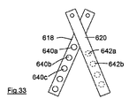
上述の様な構成は、図33及び図34に示されている。第1部分618が、図33に示す位置から図34に示す位置まで、図示する様に反時計方向に旋回すると共に、第2部分620が、これに対応して時計方向に旋回すると、第2駆動部材642bが、第2及び第3形成部材640b、640c等の間を通過する前に、第1駆動部材642aが、第1及び第2形成部材640a、640bの間を通過するため、所望の進行性変形により、上記毛足が所望の波形になることが理解されるであろう。第1部分618の基板662aは、各基板間に位置する上記形成部材及び駆動部材により、図示する様な位置、すなわち、第2部分620の基板662bの下方に位置し、その結果、駆動部材642は、図示する様に紙面の内側へ突き出す一方、形成部材640は、図示する様に紙面の外側へ突き出すことが理解されるであろう。
The configuration as described above is shown in FIGS. When the
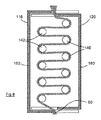
第2実施形態は、図12〜図18に示され、これらの図面が、図1〜図3に示した装置10の室24内に有益な様に(但し、これに限らず)設けることのできる構成要素を示すことが理解されるであろう。
A second embodiment is shown in FIGS. 12-18, which may be beneficially (but not limited to) provided in the
本実施形態においては、形成部材240の各々は、個別に、基板262に対して移動可能である(例えば、基板262は、主部18の底壁であってもよい)。駆動部材242もまた、個別に、基板262に対して移動可能である。上記形成部材(及び駆動部材)は、独立して移動可能であってもよい、あるいは、後述する様に、順次移動する様に関連付けられているものとしてもよい。
In the present embodiment, each of the forming members 240 is individually movable with respect to the substrate 262 (for example, the
図14〜図18からより明らかな様に、形成部材240及び駆動部材242は鏡像となっているが、他の実施形態では、同一であってもよい。形成部材及び駆動部材という用語は、一貫性を保つために使用し続けるが、これらの部材も、同一の機能を発揮するため、形成部材及び駆動部材の双方として作用する。 As is clear from FIGS. 14 to 18, the forming member 240 and the driving member 242 are mirror images, but may be the same in other embodiments. The terms forming member and drive member continue to be used for consistency, but these members also function as both the forming member and the drive member because they perform the same function.
図12及び図14に示す様な非作動位置においては、形成部材240及び駆動部材242は共に、髪入口チャネル246を規定する。髪入口チャネル246は、理想的には、装置10内の案内路26と一直線状になっている。図13及び図18に示す様な作動位置においては、部材240、242は、毛足28を所望の波形とするための形状を有する遠回りのチャネルを規定する。
In the inoperative position as shown in FIGS. 12 and 14, the forming member 240 and the drive member 242 together define a
上記一連の動作は、図14〜図18に記載されている。毛足28は、髪入口チャネル 246(上記ユーザにより直接設置されるか、または、導材30により押し込まれる)内へ導かれる。その後、第1形成部材240は、図15に示す様に、その作動位置へ移動し、毛足28を僅かに変形させる。
The above series of operations is described in FIGS. The
その後、第1形成部材242aは、図16に示す様に、その作動位置へ移動し、毛足28を更に変形させ、特に、上記毛足の一部分を、第1形成部材240aの周囲に更に曲げる。図16においては、毛足28は、第1形成部材240及び第1駆動部材242aから間隔を空けて図示されているが、実際には、双方の部材に係合することが理解されるであろう。
Thereafter, as shown in FIG. 16, the first forming
その後、第2駆動部材240bは、図17に示す様に、その作動位置へ移動し、毛足28を更に変形させ、特に、上記毛足の一部分を、第1駆動部材242aの周囲に更に曲げる。上記処理は、図18に示す様に、全ての形成部材240及び駆動部材242がその作動位置に到達するまで、継続される。
Thereafter, as shown in FIG. 17, the
第1及び第2形成部材240a、240b間に設けられた第1髪受け領域244aの形状は、上記第2形成部材が移動する時に、変化し、特に、上記毛足が上記髪受け領域内に押し込まれた後に変化することが理解されるであろう。それでもなお、上記第1駆動部材は、上記第1及び第2形成部材の間の空間内に上記毛足の一部分を入れ、上記空間は、その後に形状を変化させるものの、上記髪受け領域として規定されることが、図16から認識されるであろう。上記髪受け領域の形状変化は、隣接する形成部材240の各組毎に(同様に、隣接する駆動部材の各組毎に)類似する。
The shape of the first
本実施形態においては、形成部材240及び駆動部材242は、各旋回軸ピン264上に取り付けられ、その非作動位置及び作動位置の間を、約90°回転する。他の実施形態では、形成部材240及び駆動部材242は、90°よりもかなり少なく回転し、更に別の実施形態においては、90°よりもかなり多く回転する。更に別の実施形態では、上記形成部材及び駆動部材は、回転可能ではなく、スライド可能である。必要に応じて、上記形成部材及び駆動部材の全てが一緒に回転可能である、あるいは、上記形成部材及び駆動部材の移動は重複可能である、すなわち、上記第1駆動部材がその回転を停止する前に、上記第2形成部材がその回転を開始可能等である。 In this embodiment, the forming member 240 and the drive member 242 are mounted on each pivot pin 264 and rotate about 90 ° between their inoperative and operative positions. In other embodiments, the forming member 240 and the drive member 242 rotate significantly less than 90 °, and in yet another embodiment, rotate significantly more than 90 °. In yet another embodiment, the forming member and the drive member are not rotatable but are slidable. If necessary, all of the forming member and the driving member can be rotated together, or the movement of the forming member and the driving member can be overlapped, that is, the first driving member stops its rotation. Before, the second forming member can start its rotation and so on.
第1形成部材240aがその作動位置へ移動する間に毛足28に付与される張力は、比較的小さいことが、図15から認識されるであろう。同様に、第1駆動部材242aの移動中に付与される張力もまた、比較的小さいことが、図16から認識されるであろう。各形成部材及び各駆動部材の移動中に付与される張力は、同様に小さいため、本実施形態に記載の一連の処理は、特に、上記毛足に付与される張力を最小化するという点において有益である。
It will be appreciated from FIG. 15 that the tension applied to the bristle
更に、上記波が、毛足28の近位端(頭皮)から適用される場合、ユーザの頭皮に掛かる力、及びこれにより上記ユーザの感じる不快感は、最小化される、すなわち、後期の動作中に上記毛足の近位端48に付与される張力は、殆ど無いか、全く無い。換言すれば、第2形成部材240bがその作動位置に移動した後(そして、恐らく、第1駆動部材242aがその作動位置に移動した後でさえ)、上記形成部材及び駆動部材の更なる動作により、上記毛足の近位端48から髪を引き込もうとするよりも、上記毛足の遠位端50からの方が更に多くの毛足28を容易に引き込むことが可能であると予想される。
Furthermore, when the wave is applied from the proximal end (scalp) of the
図18は、第4駆動部材242dがその作動位置に到達した直後の位置を示す。毛足28は、第4駆動部材242dの移動中は、依然として、張力が小さい状態にあることが理解されるであろう。しかしながら、毛足28は、その自然回復力により、実質的に線形の状態に戻ろうとするため、上記毛足の各部分は、該毛足を取り囲む(その後、より多くの髪を上記装置内に引き込む)上記形成部材または駆動部材と係合する様に、伸長しようとするであろう。形成部材240及び駆動部材242の側端部266a、266bは全て弓形(理想的には部分的に円形)であり、かつ、隣り合う形成部材及び駆動部材は共に、協働する部分的に円形状の壁を提供することにより、上記毛足が上記装置内の滑らかな曲線に従うことを可能とし、その結果、滑らかな波を生成することが認識されるであろう。
FIG. 18 shows the position immediately after the
図12〜図18は、基板262の面に対して実質的に垂直である側端部266a、266bを有する形成部材240及び駆動部材242を示す。従って、形成された波は、2次元である。すなわち、図18に示す上記形成された波は、実質的に平坦であると共に、図14〜図18の紙面に対して平行である。別の実施形態においては、側端部266a、266bは、基板262の面に対して角度を有するものとしてもよく、これにより、3次元波が生成される。
12-18 illustrate the forming member 240 and the drive member 242 having side ends 266a, 266b that are substantially perpendicular to the plane of the
具体的には、各側端部266aが基板262から離れた位置に集まる様に、形成部材240は、先細形状であってもよく、側端部266bが基板262から離れた位置で分岐する様に、駆動部材242は、反対方向の先細形状であってもよい。これにより、毛足28は、駆動部材242に係合する基板262へ向かう方向へ促され、かつ、形成部材240に係合する基板262から離れる方向へ促される、という効果が得られる。上記別の実施形態に係る、図18と同様の平面図においては、毛足28は、(図18に)図示する様に、左側及び右側へ波を有すると共に、図示する様に、紙面の内側及び外側へも波を有するであろう。
Specifically, the forming member 240 may be tapered so that the
形成部材240及び駆動部材242の各々は、これらの非作動位置において、基板262を僅かに越えて突き出ることが、図14〜図17から認識されるであろう。この突出部分は、形成部材240及び駆動部材242をその作動位置へ順次移動させるために基板262の端部に沿って動かされる作動装置(アクチュエータ)により係合可能な各カムとして、機能する。上記形成部材及び駆動部材がこれらの非作動位置へ戻る動作により、上記作動装置の復帰運動が自動的に実現される様に、上記形成部材及び駆動部材は、これらの非作動位置へ向かって、弾力的に偏向されるものとしてもよい。
It will be appreciated from FIGS. 14-17 that the forming member 240 and the drive member 242 each protrude slightly beyond the
第3実施形態は、図19〜図22に示される。本実施形態では、形成部材340は、その各々が単一の旋回軸くい370上に取り付けられた各腕部368により支持される。同様に、駆動部材342は、その各々が単一の旋回軸くい374上に取り付けられた各腕部372により支持される。上記形成部材及び上記駆動部材は、図19及び図21に示す上記非作動位置から、図20及び図22に示す上記作動位置まで、移動可能である。上記移動は、好適には、連続的であり、かつ、上述の第3実施形態における動作と類似するが、上記移動は、好適には、同時発生的でなくてもよい。
The third embodiment is shown in FIGS. In this embodiment, the forming member 340 is supported by each
別の実施形態においては、上記形成部材は(上記駆動部材も同様に)、各々別個の旋回軸くい上に取り付け可能である。 In another embodiment, the forming members (as well as the drive members) can each be mounted on a separate pivot shaft.
特に、腕部368、372は、部分的に積層可能な様にずれて配設されることが、図19から判るであろう。本実施形態では、形成部材340及び駆動部材342は、作動装置(不図示)により、各々の作動位置まで、全てが確実に動かされる。別の実施形態では、形成部材340は、隣り合う駆動部材342の腕部372により係合されるものとしてもよく、駆動部材342は、隣り合う形成部材340の腕部368により係合されるものとしてもよい。係合する腕部は、形成部材340及び駆動部材342を、少なくとも部分的に、これらの作動位置まで移動させる。
In particular, it can be seen from FIG. 19 that the
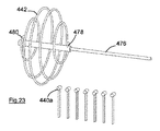
第4実施形態は、図23〜図27に示される。本実施形態は、図25に示す方向へ回転すると共に、図25に示す方向へ形成部材440の列に沿って移動もする一連の螺旋状部材442により、上記駆動部材が提供される、という点において、前述の実施形態と異なる。螺旋状部材442間の距離は、隣り合う形成部材440間の距離と厳密に一致する。
The fourth embodiment is shown in FIGS. In this embodiment, the drive member is provided by a series of
図23及び図24に示す非作動位置においては、毛足28は、形成部材440の列及び螺旋状部材442の間の髪入口チャネル446内に配置される。その後、螺旋状部材 442は、その先端478が、第1及び第2形成部材440a、440b間に設けられた第1髪受け領域444aと隣り合う上記毛足の一部分に接近するまで、移動される。
In the inoperative position shown in FIGS. 23 and 24, the bristle
その後、螺旋状部材442は、軸476により回転され、また、図示する様に右側へ移動(回転速度及び螺旋ピッチに対応する線形移動)される。螺旋状部材442の半径は、その先端478から徐々に増加するため、螺旋状部材442は、図25に示す様に、上記毛足に係合し、上記毛足の一部を上記髪受け領域内へ入れ始めることが観察されるであろう。更に、螺旋状部材442が回転(及び移動)することにより、更に多くの上記毛足が、第1髪受け領域444a内へ入れられる。
Thereafter, the
上記回転及び線形移動は、毛足28の各部分を一連の髪受け領域内へ押し込む螺旋状部材442の一連のコイルにより、図26に示す位置まで継続される。
The rotation and linear movement is continued to the position shown in FIG. 26 by a series of coils of a
上記コイルの半径は、その終端480に向かって徐々に減少する結果、巻き部材442は対称であることが判るであろう。これにより、(最大半径を有する)その中間点及び終端480間のコイルは、上記毛足を押す様に作用するのではなく、上記髪を各髪受け領域内に保持する様に作用することが理解されるであろう。従って、後半部分のコイルは、上記毛足に十分に係合し、例えば、上記毛足が第1髪受け領域444aから外に引っ張られることを防止する。換言すれば、より多くの髪を上記装置内へ引き込むのに要する力は、存在する髪の何れかの部分を髪受け領域から外に引っ張るのに要する力よりも小さい。従って、図27に示す様に、螺旋状部材442がその移動の終点に近付く時に、上記髪受け領域内へ導かれた上記毛足の部分は、保持される。但し、別の実施形態においては、必要に応じて、上記コイルは、非対称であり、その終端に至るまで最大半径を維持するものとしてもよい。
It will be appreciated that the winding
また、上記第4実施形態は、形成部材440と実質的に垂直である上記毛足に対して力を付与するという点においても、前述した実施形態と異なることが理解されるであろう。すなわち、上記コイルは、図25に示す様に、紙面内へ向かう方向の小さな摩擦力を、上記毛足に対して与える。1つ以上の弾性的な蓋(不図示)が、形成部材440と隣り合って設けられるものとしてもよい。これにより、螺旋コイル442の回転を可能としつつ、上記毛足を、上記形成部材に接触した状態に維持することが可能となるであろう。また、上記毛足が形成部材から分離されてしまう恐れを回避するために、上記形成部材は、(図24〜図27の紙面内へ向かう方向に)図23に示すよりもかなり幅広に形成されるものとしてもよい。第4実施形態は、図23〜図27に示される。本実施形態は、
In addition, it will be understood that the fourth embodiment differs from the above-described embodiment in that a force is applied to the hair foot that is substantially perpendicular to the forming member 440. That is, as shown in FIG. 25, the coil gives a small frictional force in the direction toward the paper surface to the hair feet. One or more elastic lids (not shown) may be provided adjacent to the forming member 440. This will allow the bristles to be kept in contact with the forming member while allowing the
第5実施形態は、図28〜図32に示される。前述の実施形態では、上記毛足の異なる部分毎に、個別の髪受け領域が提供される。第5実施形態は、上記毛足の複数の部分が、提供される2つの髪受け領域の各々の中に入れられる、という点において異なる。 The fifth embodiment is shown in FIGS. In the above-described embodiment, a separate hair receiving area is provided for each different part of the hair. The fifth embodiment is different in that a plurality of portions of the hair feet are placed in each of the two provided hair receiving areas.
第5実施形態は、その各々が、基板562に堅く固定される支柱を有する(例えば、該基板は、主部18の底壁であってもよい)第1及び第2形成部材540a、540bを有する。上記第1及び第2形成部材間には隙間が存在し、該隙間が、第1髪受け領域544aを提供する。第1駆動部材542aは、旋回軸くい574a上に枢動可能に取り付けられ、図28に示す様な非作動位置から、図29に示す様な作動位置へ移動可能である。
The fifth embodiment includes first and second forming
特に、図29からは、駆動部材542aが、旋回軸くい574a及び第1髪受け領域 544a間の距離と近似する曲率半径を有する弓形であることが理解されるであろう。従って、第1駆動部材542aは、その非作動位置からその作動位置まで、旋回軸くいの周りを回転可能であり、毛足28の一部分を、第1及び第2形成部材540a、540b間の第1髪受け領域544a内へ入れる。
In particular, it will be appreciated from FIG. 29 that the
また、第3及び第4形成部材540c、540dも、基板562に堅く固定され、上記第3及び第4形成部材間の隙間は、第2髪受け領域544bを提供する。第2駆動部材542bは、旋回軸くい574b上に枢動可能に取り付けられ、図30に示す様な非作動位置から、図31に示す様な作動位置へ移動可能である。
The third and fourth forming
第2駆動部材 542bは、第1駆動部材542aと同様の構成を有するため、図31に示す様に、第3及び第4形成部材540c、540d間の第2髪受け領域544b内へ、毛足28の別の部分を入れることができる。
Since the
上記図面には示さないが、第1及び第2形成部材540a、540b間には(並びに、第3及び第4形成部材540c、540d間にも同様に)、1つまたは複数の弾性的な蓋が設けられる。該弾性的な蓋は、駆動部材542の通路を妨げることも、該通路を経由する上記毛足の一部分を動かすこともないが、上記髪受け領域内に一旦押し込まれると、上記毛足の一部分を保持する様に作用する。従って、図30に示す様に、第1駆動部材542aが、その非作動位置へ引っ込められると、上記毛足の部分28aは、上記弾性部材により、第1髪受け領域544a内に保持される。代替的には、上記第1及び第2形成部材は、弾力性を有するものとしてもよい、または、その基部に対して移動可能な様に弾力的に取り付けられるものとしてもよい。これにより、上記駆動部材の通路は、上記第1及び第2形成部材間の髪の部分を保持することもできる。
Although not shown in the above drawings, one or more elastic lids are provided between the first and second forming
更に、第2駆動部材542bが、上記毛足の別の部分28bを、第2髪受け領域544b内に入れる時、上記第1髪受け領域から外に引き戻されている毛足の部分28aではなく、更なる髪が、遠位端50から、上記装置に引き込まれる。
Furthermore, when the
図32は、駆動部材542a、542bの各々が、1周期の動作、すなわち、その非作動位置から作動位置へ移動し、再び非作動位置まで戻るという動作、を開始した状態を示す。上記一連の動作は、上記第1及び第2駆動部材の交互の運動により、繰り返し可能であり、これにより、毛足28の更なる部分は、第1及び第2髪受け領域544a、544b内に押し込まれることが理解されるであろう。
FIG. 32 shows a state in which each of the driving
上述した全ての実施形態において、生成される波の大きさ(サイズ)は、上記髪受け領域の大きさ(特に深さ)、特に、上記髪受け領域内に押し込まれる毛足の各部分の線形の範囲に依存することが理解されるであろう。大きな波を生成することが望ましいこともあるが、通常は、小さな波ほど、より美しいと考えられる。従って、波形の毛足内における一連の曲線間の実質的に線形である髪の部分は、上記髪の外観を良くすることに、殆ど貢献しない。それ故、発明者は、多数の小さな波を生成することのできる装置を提供することが好ましい。従って、発明者は、密に配置された小さな髪受け領域を有することにより、隣り合う曲線間における上記毛足の線形範囲を減少させる装置の提供を追求する。 In all the embodiments described above, the magnitude (size) of the generated wave is the size (especially the depth) of the hair receiving area, in particular the linearity of each part of the hair foot that is pushed into the hair receiving area. It will be understood that it depends on the scope of While it may be desirable to generate large waves, it is usually considered that smaller waves are more beautiful. Accordingly, a portion of the hair that is substantially linear between a series of curves within the corrugated hair foot contributes little to improving the appearance of the hair. Therefore, the inventor preferably provides a device that can generate a large number of small waves. Accordingly, the inventor seeks to provide an apparatus that reduces the linear range of the above-mentioned hair feet between adjacent curves by having closely spaced small hair receiving areas.
また、発明者は、上記スタイリング(ウェービング)工程中にヘアトリートメント製品を上記毛足に付けるために使用可能なヘアスタイリング装置の提供も追求する。上記ヘアトリートメント製品は、蒸気、上記毛足をコンディショニング若しくはトリートメントするための化学物質、または、これら双方の組み合わせであってもよい。上記毛足を室内に保持することは、とりわけ、ヘアトリートメント製品を追加するために有益であり、上記室が、実質的に連続した壁によって取り囲まれると、当該環境におけるヘアトリートメント製品の損失を最小限に抑えることが可能となる。 The inventor also seeks to provide a hair styling device that can be used to apply a hair treatment product to the hair foot during the styling (waving) process. The hair treatment product may be steam, a chemical for conditioning or treating the hair foot, or a combination of both. Holding the bristles indoors is particularly beneficial for adding hair treatment products, and when the chamber is surrounded by a substantially continuous wall, it minimizes the loss of hair treatment products in the environment. It becomes possible to limit to the limit.
特に好適な実施形態においては、例えば、加熱器(好適には、電熱器)を、上記室の1つ以上の壁内に組み入れることにより、上記室は、直接加熱される。ヘアトリートメント製品は、上記室に接続するポートを介して、付与することができる。特に、図12〜図18に示す第2実施形態に代替する態様においては、旋回軸ピン264は、蒸気、及び/または液化若しくは気化したヘアトリートメント製品の通路を、上記形成部材及び上記駆動部材内に形成可能な様に、部分的に中が空洞であってもよい。これらの部材は、上記蒸気または製品を、上記毛足に隣り合う室内に移行可能とするための出口用ポートを有する。旋回軸ピン264は、装置10の主部若しくは柄部内の水及び/または選択されたヘアトリートメント製品のための容器と滑らかに連結するものとしてもよい。あるいは、基板262は、上記形成部材及び駆動部材が作動位置にある時にこれらの部材により覆われるポートを有するものとしてもよい。該ポートは、蒸気及び/またはヘアトリートメント製品を、その後に上記毛足に散布するために、上記形成部材及び駆動部材内に供給する様に、構成される。
In particularly preferred embodiments, the chamber is heated directly, for example by incorporating a heater (preferably an electric heater) into one or more walls of the chamber. The hair treatment product can be applied via a port connected to the chamber. In particular, in a mode alternative to the second embodiment shown in FIGS. 12 to 18, the pivot pin 264 has a path for steam and / or a liquefied or vaporized hair treatment product in the forming member and the driving member. The inside may be partially hollow so that it can be formed. These members have an outlet port for allowing the steam or product to move into a room adjacent to the hair feet. The pivot pin 264 may smoothly connect with water in the main portion or handle of the
上記室内にポートを設けることは、ヘアトリートメント製品を用いることなく使用可能な様に設計された実施形態においてさえ、有益であり得る。具体的には、熱風は、理想的には収容された毛足に直接隣接する内部ポートを介して、上記室内に吹き付けられるものとしてもよい。上記熱風は、上記髪を加熱すると共に、上記スタイリング工程を迅速化する様に作用し、(好適には、上記熱風は、上記室の加熱された壁により与えられる熱に対して付加されるものであるが、)必要に応じて、上記毛足を加熱するための唯一の手段となり得る。 Providing a port in the chamber can be beneficial even in embodiments designed to be usable without using a hair treatment product. Specifically, the hot air may be blown into the room ideally through an internal port directly adjacent to the housed hair. The hot air heats the hair and acts to expedite the styling process (preferably the hot air is added to the heat provided by the heated wall of the chamber. However, if necessary) it can be the only means for heating the hair feet.
上述の実施形態は、上記ユーザの髪に、実質的に一貫性のある波を生成するために使用することができる。代替的な波形は、上記形成部材及び/または上記駆動部材を(これらの作動位置において)非直線状の列に配置することにより、あるいは、必要に応じて、幾つかの上記形成部材及び上記駆動部材の形状及び/または横断面サイズ及び/または間隔を変更することにより、生成することができる。 The above-described embodiments can be used to generate a substantially consistent wave in the user's hair. An alternative corrugation can be achieved by placing the forming members and / or the drive members in non-linear rows (in these operating positions) or, if necessary, several of the forming members and the drives. It can be generated by changing the shape and / or cross-sectional size and / or spacing of the members.
上記波形となった髪は、ウェービング工程の最後において、上記毛足をその近位端から引っ張ることにより、上記装置から容易に取り除き可能であることが理解されるであろう。しかしながら、上記髪がその除去処理中に張力を受ける場合、特に、上記髪が、形成された波に反して曲げられる場合に、上記形成された波の多くが損なわれることは好ましくない。このため、上記形成部材及び/または駆動部材を、これらの非作動位置へ戻してパネル20を開くことにより、開口部22を用いて、実質的に負荷を与えることなく、波形の毛足を上記装置から除去可能とすることが望ましい。
It will be appreciated that the corrugated hair can be easily removed from the device at the end of the waving process by pulling the hair foot from its proximal end. However, it is not preferred that many of the formed waves are impaired when the hair is subjected to tension during its removal process, especially when the hair is bent against the formed waves. For this reason, by opening the
好適な実施形態においては、上記装置は、上記駆動部材の移動、及び、例えば発熱体等の、上記装置の他の構成要素を、制御するための制御装置を有する。上記制御装置は、ヘアウェービング動作の継続時間を決定することができる様に、タイマーを有するものとしてもよい。すなわち、上記発熱体は、所定時間の経過後に停止(スイッチオフ)されると共に、視覚信号または音声信号が、上記ユーザに発せられて、上記室を開けて波形の毛足を取り出し可能である旨の通知を行う。 In a preferred embodiment, the device comprises a control device for controlling the movement of the drive member and other components of the device, for example a heating element. The said control apparatus is good also as what has a timer so that the duration of hair waving operation | movement can be determined. That is, the heating element is stopped (switched off) after a lapse of a predetermined time, and a visual signal or an audio signal is issued to the user so that the chamber can be opened and the corrugated hair can be taken out. Notification.
上記装置の内、選択された構成要素は、上記制御装置が上記装置の動作を監視することができる様に、上記制御装置に対して、フィードバック信号を発するものとしてもよい。上述した様に、上記装置は、上記遮閉要素が閉じられたことを通知するためのセンサを設けるものとしてもよい。上記制御装置は、上記センサからの信号が受信された場合にのみ、上記駆動部材の移動を開始させるための信号を発する。他のフィードバック信号は、上記駆動部材を移動させるモータにより発せられるものとしてもよい。これにより、該モータに対する高い負荷が髪の絡まりを示す可能性がある、または、あまりに多くの髪が上記装置内に設置されたとの認識が為される。上記制御装置は、負荷の閾値を格納し、該閾値を超えた場合に、上記駆動部材の移動を停止(及び恐らく逆転)させるものとしてもよい。 A selected component of the device may issue a feedback signal to the control device so that the control device can monitor the operation of the device. As described above, the device may be provided with a sensor for notifying that the blocking element is closed. The control device emits a signal for starting the movement of the driving member only when a signal from the sensor is received. Another feedback signal may be generated by a motor that moves the drive member. As a result, it is recognized that a high load on the motor may indicate entanglement of hair, or that too much hair is installed in the apparatus. The control device may store a load threshold and stop (and possibly reverse) the movement of the drive member when the threshold is exceeded.
また、上記装置は、該装置内に設置された毛足の厚さを決定するための手段を有するものとしてもよい。上記制御装置は、幾つかのパラメータ(例えば、上記加熱器の温度、上記駆動部材の移動速度、及び動作期間)の設定値を格納すると共に、上記毛足の厚さに基づき、特定の毛足をウェービングするために使用される上記パラメータを決定するものとしてもよい。 Moreover, the said apparatus may have a means for determining the thickness of the hair foot installed in this apparatus. The control device stores set values of several parameters (for example, the temperature of the heater, the moving speed of the driving member, and the operation period), and based on the thickness of the bristle foot, It is also possible to determine the above parameters used for waving.
10 ヘアスタイリング装置
12 第1柄部
14 第2柄部
16 旋回軸ピン
18 主部
20 パネル
22 開口部
24 室
26 案内路
28 毛足
30 導材
32 ピン
34 チャネル
40a 第1形成部材
40b 第2形成部材
42a 第1駆動部材
42b 第2駆動部材
44a 第1髪受け領域
44b 第2髪受け領域
46 髪入口チャネル
48 近位端
50 遠位端
110 装置
118 第1部分
120 第2部分
124 室
140 第1支柱
142 第2支柱
146 髪入口チャネル
152、154、156、158、160、162 壁
240a 第1形成部材
240b 第2駆動部材
242a 第1駆動部材
242d 第4駆動部材
244a 第1髪受け領域
246 髪入口チャネル
262 基板
264 旋回軸ピン
266a、266b 側端部
368、372 腕部
370、374 旋回軸くい
440a 第1形成部材
440b 第2形成部材
442 螺旋状部材
444a 第1髪受け領域
446 髪入口チャネル
476 軸
478 先端
480 終端
540a 第1形成部材
540b 第2形成部材
540c 第3形成部材
540d 第4形成部材
542a 第1駆動部材
542b 第2駆動部材
544a 第1髪受け領域
544b 第2髪受け領域
562 基板
574a、574b 旋回軸くい
618 第1部分
620 第2部分
640a 第1形成部材
640b 第2形成部材
642a 第1駆動部材
642b 第2駆動部材
662a、662b 基板
DESCRIPTION OF
Claims (15)
前記毛足を収容するための室、
前記室内の第1形成部材及び第2形成部材、
前記第1形成部材及び前記第2形成部材間の第1髪受け領域、並びに
前記第1髪受け領域外の非作動位置、及び前記第1髪受け領域内の作動位置間を、前記第1形成部材に対して移動可能な第1駆動部材
を有するヘアスタイリング装置。 A hair styling device for imparting waves to hairs,
A chamber for accommodating the hair feet,
A first forming member and a second forming member in the chamber;
A first hair receiving region between the first forming member and the second forming member, a non-operating position outside the first hair receiving region, and an operating position in the first hair receiving region are the first formation. The hair styling apparatus which has a 1st drive member movable with respect to a member.
前記第2髪受け領域外の非作動位置、及び前記第2髪受け領域内の作動位置間を、前記第2形成部材に対して移動可能な第2駆動部材
を有する、請求項1に記載のヘアスタイリング装置。 A third forming member having a second hair receiving area between the second forming member and the third forming member; a non-operating position outside the second hair receiving area; and an operating position within the second hair receiving area. The hair styling device according to claim 1, further comprising a second drive member that is movable relative to the second forming member.
前記第1駆動部材及び前記第2駆動部材間に髪受け領域が更に存在する、請求項2または請求項3に記載のヘアスタイリング装置。 The drive member and the forming member are all formed in the same manner,
The hair styling device according to claim 2 or 3, wherein a hair receiving region further exists between the first driving member and the second driving member.
前記遮閉要素は、第2柄部上に取り付けられ、
前記第1及び第2柄部は、相互に移動可能であり、前記室の開状態及び閉状態を規定する、請求項11または請求項12に記載のヘアスタイリング装置。 At least a part of the chamber is provided in a main part attached on the first handle part,
The shielding element is mounted on the second handle;
The hair styling device according to claim 11 or 12, wherein the first and second handle portions are movable with respect to each other and define an open state and a closed state of the chamber.
{i}前記第1形成部材及び前記第1駆動部材間の髪入口チャネル内に毛足を導く工程;
{ii}前記第1駆動部材をその非作動位置からその作動位置へ移動させると共に、前記毛足の一部を前記第1髪受け領域内へ送る工程;及び
{iii}前記室を加熱する工程
を含む方法。 A method using the hair styling device according to any one of claims 1 to 14, comprising:
{I} directing a hair foot into a hair inlet channel between the first forming member and the first drive member;
{Ii} moving the first drive member from its non-actuated position to its actuated position, and sending a portion of the bristles into the first hair receiving area; and {iii} heating the chamber Including methods.
Applications Claiming Priority (2)
| Application Number | Priority Date | Filing Date | Title |
|---|---|---|---|
| GBGB1302043.3A GB201302043D0 (en) | 2013-02-05 | 2013-02-05 | Hair styling device |
| PCT/GB2014/050296 WO2014122442A1 (en) | 2013-02-05 | 2014-02-03 | Hair styling device |
Publications (2)
| Publication Number | Publication Date |
|---|---|
| JP2017505209A true JP2017505209A (en) | 2017-02-16 |
| JP6722115B2 JP6722115B2 (en) | 2020-07-15 |
Family
ID=47988759
Family Applications (1)
| Application Number | Title | Priority Date | Filing Date |
|---|---|---|---|
| JP2016564421A Active JP6722115B2 (en) | 2013-02-05 | 2014-02-03 | Hair styling equipment |
Country Status (17)
| Country | Link |
|---|---|
| US (1) | US10772406B2 (en) |
| EP (1) | EP3102063B1 (en) |
| JP (1) | JP6722115B2 (en) |
| KR (1) | KR102240011B1 (en) |
| CN (1) | CN105939632B (en) |
| AU (1) | AU2014213769B2 (en) |
| CA (1) | CA2938585C (en) |
| CR (1) | CR20160401A (en) |
| ES (1) | ES2962527T3 (en) |
| GB (2) | GB201302043D0 (en) |
| MX (1) | MX2016010021A (en) |
| MY (1) | MY182660A (en) |
| RU (1) | RU2672612C1 (en) |
| SA (1) | SA516371607B1 (en) |
| TW (1) | TWI623286B (en) |
| WO (1) | WO2014122442A1 (en) |
| ZA (1) | ZA201606081B (en) |
Cited By (1)
| Publication number | Priority date | Publication date | Assignee | Title |
|---|---|---|---|---|
| JP2020537574A (en) * | 2017-10-17 | 2020-12-24 | エイチディースリー リミテッド | Hair styling device, hair styling method, and drive system |
Families Citing this family (5)
| Publication number | Priority date | Publication date | Assignee | Title |
|---|---|---|---|---|
| US12495891B1 (en) | 2018-03-22 | 2025-12-16 | Nashara Frazier | Hair styling tool and method of use |
| GB2614463B (en) | 2018-06-15 | 2024-04-10 | Japham Group Ltd | Hair styling device |
| GB201902443D0 (en) | 2019-02-22 | 2019-04-10 | Hd3 Ltd | Hair styling device |
| GB202314517D0 (en) | 2023-09-21 | 2023-11-08 | Japham Group Ltd | Hair styling device |
| GB2639876A (en) * | 2024-03-26 | 2025-10-08 | Dyson Technology Ltd | Hairstyling appliance |
Citations (10)
| Publication number | Priority date | Publication date | Assignee | Title |
|---|---|---|---|---|
| US1694672A (en) * | 1925-02-23 | 1928-12-11 | Rogler Max | Hair-curling means |
| GB303043A (en) * | 1927-09-26 | 1928-12-27 | Ernest Holman | Improvements in or relating to devices for curling or waving hair |
| JPS5977805A (en) * | 1982-10-27 | 1984-05-04 | 山本 久博 | Formation of permanent wave |
| JPS60140502U (en) * | 1984-02-28 | 1985-09-18 | 斉藤 明 | cold permanent tools |
| JPS6147902U (en) * | 1984-09-03 | 1986-03-31 | 健治 堀江 | hair winder |
| JPS6287105A (en) * | 1985-10-14 | 1987-04-21 | 松下電工株式会社 | Hair conditioning appliance |
| JPS6278801U (en) * | 1985-11-05 | 1987-05-20 | ||
| JPS62115802U (en) * | 1986-01-16 | 1987-07-23 | ||
| JPS633808A (en) * | 1986-06-25 | 1988-01-08 | 松下電工株式会社 | Hair dryer |
| JP2002520076A (en) * | 1998-07-09 | 2002-07-09 | ボルマスター アクティエボラーグ | Hair arrangement device and hair tong provided with such device |
Family Cites Families (89)
| Publication number | Priority date | Publication date | Assignee | Title |
|---|---|---|---|---|
| US1806711A (en) | 1931-05-26 | Morris salzhtan | ||
| DE172581C (en) * | 1905-02-16 | 1906-07-05 | CURL SCISSORS WITH MULTI-CURLATING HANDLES | |
| US1609810A (en) * | 1926-02-27 | 1926-12-07 | Harry C Gates | Marcelling iron |
| US1636967A (en) | 1926-05-13 | 1927-07-26 | Perry Elsie | Permanent-marcel-wave apparatus |
| FR641097A (en) | 1927-09-20 | 1928-07-27 | Device for so-called permanent waving | |
| GB302952A (en) | 1927-09-21 | 1928-12-21 | Gustav Dinger | Improvements in or relating to hair curling appliances |
| US1827785A (en) | 1927-10-27 | 1931-10-20 | Ernest O Frederics | Method and means for sectional treatment in permanent waving of hair |
| US1709981A (en) * | 1927-12-14 | 1929-04-23 | Headington Susanna Cocroft | Process of and apparatus for waving hair |
| US1701270A (en) * | 1928-04-21 | 1929-02-05 | Moskovitz Sophie | Hair waver |
| US1831487A (en) | 1930-12-18 | 1931-11-10 | Oscar J Elam | Hair waving appliance |
| US1877776A (en) | 1931-04-10 | 1932-09-20 | Pezzella Rocco | Hair wrapping instrument |
| US1884305A (en) | 1931-06-26 | 1932-10-25 | Shelton William Gentry | Hair curling apparatus and method |
| US1894624A (en) | 1931-09-03 | 1933-01-17 | Francois R Marcel | Permanent waving device |
| US1895653A (en) | 1932-04-25 | 1933-01-31 | Fisher Sol | Hair waving and curling rod |
| US1981362A (en) | 1933-05-18 | 1934-11-20 | William H Joyce | Wrapper for use in hair waving processes |
| US2595844A (en) | 1950-08-22 | 1952-05-06 | Edith M Graham | Hair curler |
| US2791225A (en) | 1952-12-01 | 1957-05-07 | Simmons Stanley | Vacuum hair curler |
| US2906272A (en) | 1956-07-24 | 1959-09-29 | Eugene A Heidel | Apparatus for producing pin curls |
| US2935070A (en) | 1957-01-02 | 1960-05-03 | Cape E Auz | Hair curling device |
| US2867223A (en) | 1957-03-06 | 1959-01-06 | Rose L Anzalone | Hair curling device |
| BE632129A (en) | 1962-05-09 | |||
| US3255765A (en) | 1962-10-16 | 1966-06-14 | Jules H Heims | Automatic coiling hair curler |
| US3223093A (en) | 1963-01-17 | 1965-12-14 | Charles E Winters | Vacuum hair curler |
| US3213859A (en) | 1963-03-01 | 1965-10-26 | Gillette Co | Device for curling hair by suction |
| GB1157814A (en) | 1965-07-19 | 1969-07-09 | Skyline Oil Company | Hair Curler |
| US3786819A (en) | 1971-10-18 | 1974-01-22 | A Cantrell | Apparatus and method for treating hair |
| US3805810A (en) | 1972-11-13 | 1974-04-23 | D Savala | Device and method for treating hair |
| US3835292A (en) | 1973-02-28 | 1974-09-10 | Clairol Inc | Steam curling iron |
| JPS51141181U (en) * | 1975-05-07 | 1976-11-13 | ||
| US3968805A (en) | 1975-09-08 | 1976-07-13 | Sobeck Jr Thomas J | Hair treatment apparatus |
| US4222398A (en) | 1976-08-05 | 1980-09-16 | Dennis L. Taelman | Electrically powered hair rolling device |
| IT1067953B (en) | 1976-12-20 | 1985-03-21 | Gnaga Vittorio | APPARATUS FOR AUTOMATIC CURLING OF THE HAIR |
| IT1079587B (en) | 1977-02-09 | 1985-05-13 | Gnaga Vittorio | BIGODINO MOTOR COMPLEX FOR THE AUTOMATIC APPLICATION OF BIGODINI TO THE HAIR |
| JPS6110102U (en) | 1984-06-25 | 1986-01-21 | 晃一 星野 | automatic hair curler |
| US4829156A (en) | 1987-04-15 | 1989-05-09 | Thompson Robert I | Electric curling iron having a reversible motor-driven rotatable curling mandrel |
| US4884583A (en) | 1988-01-11 | 1989-12-05 | Long Jr Oscar C | Hair roller and rotating apparatus |
| US5119847A (en) | 1990-09-10 | 1992-06-09 | Quartern Group | Apparatus and method for axially twisting hair |
| GB9119557D0 (en) | 1991-09-13 | 1991-10-23 | Beneditis Alfredo De | Method of treating hair |
| JPH07303513A (en) * | 1993-04-06 | 1995-11-21 | Toshihiro Kimata | Hair treating method and device for permanent waving |
| US5472003A (en) | 1994-01-14 | 1995-12-05 | Frame; Chad R. | Hair accessory for ponytail |
| GB2287403B (en) | 1994-02-28 | 1997-08-27 | Benedictis Alfredo De | Device and method for treatment of hair |
| BE1009997A3 (en) | 1996-01-31 | 1997-11-04 | Patrick Brams | Bigoudi. |
| CN2272228Y (en) * | 1996-05-03 | 1998-01-14 | 郝志铠 | Hair curling device |
| GB9611816D0 (en) | 1996-06-06 | 1996-08-07 | Benedictis Alfredo De | Hair treatment device |
| GB9817618D0 (en) | 1998-08-14 | 1998-10-07 | Benedictis Alfredo De | Hair treatment device and method |
| WO2000057744A1 (en) | 1999-03-30 | 2000-10-05 | Alfredo De Benedictis | Hair treatment device and method |
| WO2001062118A1 (en) * | 2000-02-23 | 2001-08-30 | Choi, Yong, Sik | Hair setting device |
| KR20010088269A (en) * | 2000-03-10 | 2001-09-26 | 이만택 | Hair iron |
| ES2247147T3 (en) | 2000-07-21 | 2006-03-01 | Ursula Kraus | ROLL ELEMENT FOR HAIR MOLDING, AS WELL AS A CLAMPING ELEMENT FOR A ROLL ELEMENT. |
| WO2003007752A1 (en) | 2001-07-19 | 2003-01-30 | Kao Corporation | Hair treating implement |
| JP2005324073A (en) | 2001-07-19 | 2005-11-24 | Kao Corp | Hair treatment equipment |
| ATE321469T1 (en) | 2001-07-26 | 2006-04-15 | Benedictis Danielle Anita De | METHOD AND DEVICE FOR TREATING HAIR STRANDS |
| US6637441B2 (en) | 2002-01-14 | 2003-10-28 | Spectrum Associates Llc | Hair wrapper |
| JP3998529B2 (en) | 2002-07-25 | 2007-10-31 | 花王株式会社 | Hair retainer |
| US6962159B1 (en) | 2002-09-07 | 2005-11-08 | Michael Adam | Hair styler |
| DE60221022T2 (en) | 2002-11-14 | 2008-03-13 | The Procter & Gamble Company, Cincinnati | Device for treating strands of hair and method for treating strands of hair |
| EP1584258B1 (en) | 2003-01-15 | 2012-04-18 | Kao Corporation | Hair inserter |
| GB0310288D0 (en) | 2003-05-03 | 2003-06-11 | Imij Property Holdings Ltd | A hair styling device |
| US20040237991A1 (en) | 2003-05-30 | 2004-12-02 | Glucksman Dov Z. | Hair wrapping device |
| JP3919711B2 (en) | 2003-07-31 | 2007-05-30 | 花王株式会社 | Thread insertion type and thread insertion method |
| WO2005020741A2 (en) | 2003-09-02 | 2005-03-10 | Kellie Lee Ryan-Jakimas | Convertible hair roller |
| WO2005067761A1 (en) | 2004-01-15 | 2005-07-28 | Kao Corporation | Hair holding instrument |
| EP1714576A4 (en) | 2004-02-09 | 2007-04-11 | Kao Corp | Hair holder |
| US20080035167A1 (en) | 2004-02-20 | 2008-02-14 | Dickson Industrial Co., Ltd. | Hair Styling Apparatus |
| WO2005082198A1 (en) | 2004-02-20 | 2005-09-09 | Dickson Industrial Co. Ltd. | Hair styling apparatus |
| EP1610642B1 (en) | 2004-04-10 | 2006-08-02 | Henkel Kommanditgesellschaft auf Aktien | Hair roller |
| US20050241663A1 (en) | 2004-04-29 | 2005-11-03 | Getahun Dereje K | Hair twister |
| JP2006015121A (en) | 2004-06-03 | 2006-01-19 | Toshihiro Kimata | Hair curling tool and method of curling hair |
| US20050284493A1 (en) | 2004-06-24 | 2005-12-29 | Allen Racquel R | Hair setter |
| JP2006334109A (en) * | 2005-06-01 | 2006-12-14 | Matsushita Electric Works Ltd | Hair setting apparatus |
| US8393338B2 (en) | 2005-06-02 | 2013-03-12 | The Procter & Gamble Company | Cosmetic applicator with torque limiter |
| US20070017541A1 (en) | 2005-07-25 | 2007-01-25 | Wilmore Delois A | Hair twist |
| DE102005035609A1 (en) | 2005-07-29 | 2007-03-29 | Wella Ag | Device and method for wrapping a strand of hair |
| US20080302381A1 (en) | 2005-09-12 | 2008-12-11 | Kao Corporation | Hair Holder |
| WO2007100088A1 (en) | 2006-03-03 | 2007-09-07 | Kao Corporation | Hair holder, switching jig for the hair holder and hair holder for hair treatment |
| US8132575B2 (en) | 2006-03-03 | 2012-03-13 | Kao Corporation | Hair holder |
| DE102006037647A1 (en) | 2006-08-10 | 2008-02-14 | Braun Gmbh | Hardening device with guide device and method for hair shaping |
| FR2913570B1 (en) | 2007-03-16 | 2011-02-11 | Seb Sa | HAIRSTYLING APPARATUS |
| FR2916944B1 (en) | 2007-06-11 | 2009-08-14 | Seb Sa | HAIRSTYLING APPARATUS |
| GB2455716C (en) | 2007-12-17 | 2013-02-20 | Tf3 Ltd | A hair styling aid |
| KR101178609B1 (en) * | 2010-01-07 | 2012-08-30 | (주)제이월드텍 | Curling Iron |
| US9049913B2 (en) | 2010-03-09 | 2015-06-09 | Conair Corporation | Styling brush with spinning attachment |
| FR2960747A1 (en) | 2010-06-07 | 2011-12-09 | Seb Sa | HAIRSTANDING APPARATUS WITH MOTORIZED CHUCK |
| GB201021458D0 (en) | 2010-12-17 | 2011-02-02 | Tf3 Ltd | Hair styling device |
| US20120186601A1 (en) | 2011-01-25 | 2012-07-26 | Susan Cohen Ungar | Device for assisting with hair styling |
| GB201107671D0 (en) | 2011-05-09 | 2011-06-22 | Sf3 Ltd | Improved hair styling device |
| KR101326656B1 (en) * | 2012-04-06 | 2013-11-07 | 최진호 | A curling iron appearing and disappearing the teeth of a comb |
| GB201210274D0 (en) | 2012-06-11 | 2012-07-25 | Tf3 Ltd | Hair styling device |
| CN202842684U (en) * | 2012-10-25 | 2013-04-03 | 管彦琴 | One-piece weave shaping clip |
-
2013
- 2013-02-05 GB GBGB1302043.3A patent/GB201302043D0/en not_active Ceased
-
2014
- 2014-02-03 CR CR20160401A patent/CR20160401A/en unknown
- 2014-02-03 RU RU2016129702A patent/RU2672612C1/en active
- 2014-02-03 ES ES14706929T patent/ES2962527T3/en active Active
- 2014-02-03 JP JP2016564421A patent/JP6722115B2/en active Active
- 2014-02-03 CA CA2938585A patent/CA2938585C/en active Active
- 2014-02-03 KR KR1020167022037A patent/KR102240011B1/en active Active
- 2014-02-03 MY MYPI2016702792A patent/MY182660A/en unknown
- 2014-02-03 MX MX2016010021A patent/MX2016010021A/en unknown
- 2014-02-03 WO PCT/GB2014/050296 patent/WO2014122442A1/en not_active Ceased
- 2014-02-03 EP EP14706929.8A patent/EP3102063B1/en active Active
- 2014-02-03 CN CN201480074199.0A patent/CN105939632B/en active Active
- 2014-02-03 GB GB1514523.8A patent/GB2526716B/en active Active
- 2014-02-03 US US15/115,686 patent/US10772406B2/en active Active
- 2014-02-03 AU AU2014213769A patent/AU2014213769B2/en active Active
- 2014-02-05 TW TW103103793A patent/TWI623286B/en not_active IP Right Cessation
-
2016
- 2016-08-03 SA SA516371607A patent/SA516371607B1/en unknown
- 2016-09-01 ZA ZA2016/06081A patent/ZA201606081B/en unknown
Patent Citations (10)
| Publication number | Priority date | Publication date | Assignee | Title |
|---|---|---|---|---|
| US1694672A (en) * | 1925-02-23 | 1928-12-11 | Rogler Max | Hair-curling means |
| GB303043A (en) * | 1927-09-26 | 1928-12-27 | Ernest Holman | Improvements in or relating to devices for curling or waving hair |
| JPS5977805A (en) * | 1982-10-27 | 1984-05-04 | 山本 久博 | Formation of permanent wave |
| JPS60140502U (en) * | 1984-02-28 | 1985-09-18 | 斉藤 明 | cold permanent tools |
| JPS6147902U (en) * | 1984-09-03 | 1986-03-31 | 健治 堀江 | hair winder |
| JPS6287105A (en) * | 1985-10-14 | 1987-04-21 | 松下電工株式会社 | Hair conditioning appliance |
| JPS6278801U (en) * | 1985-11-05 | 1987-05-20 | ||
| JPS62115802U (en) * | 1986-01-16 | 1987-07-23 | ||
| JPS633808A (en) * | 1986-06-25 | 1988-01-08 | 松下電工株式会社 | Hair dryer |
| JP2002520076A (en) * | 1998-07-09 | 2002-07-09 | ボルマスター アクティエボラーグ | Hair arrangement device and hair tong provided with such device |
Cited By (2)
| Publication number | Priority date | Publication date | Assignee | Title |
|---|---|---|---|---|
| JP2020537574A (en) * | 2017-10-17 | 2020-12-24 | エイチディースリー リミテッド | Hair styling device, hair styling method, and drive system |
| JP7296639B2 (en) | 2017-10-17 | 2023-06-23 | エイチディースリー リミテッド | Hair styling device, hair styling method and drive system |
Also Published As
| Publication number | Publication date |
|---|---|
| TWI623286B (en) | 2018-05-11 |
| ZA201606081B (en) | 2021-06-30 |
| GB2526716A (en) | 2015-12-02 |
| US10772406B2 (en) | 2020-09-15 |
| EP3102063C0 (en) | 2023-10-18 |
| CA2938585C (en) | 2021-07-06 |
| KR20160108482A (en) | 2016-09-19 |
| CA2938585A1 (en) | 2014-08-14 |
| US20170006989A1 (en) | 2017-01-12 |
| GB201514523D0 (en) | 2015-09-30 |
| EP3102063B1 (en) | 2023-10-18 |
| GB201302043D0 (en) | 2013-03-20 |
| JP6722115B2 (en) | 2020-07-15 |
| MX2016010021A (en) | 2017-05-09 |
| GB2526716B (en) | 2020-09-30 |
| AU2014213769B2 (en) | 2019-11-21 |
| WO2014122442A1 (en) | 2014-08-14 |
| CN105939632A (en) | 2016-09-14 |
| SA516371607B1 (en) | 2018-10-04 |
| AU2014213769A1 (en) | 2016-08-18 |
| CN105939632B (en) | 2019-09-03 |
| EP3102063A1 (en) | 2016-12-14 |
| MY182660A (en) | 2021-01-28 |
| KR102240011B1 (en) | 2021-04-13 |
| RU2672612C1 (en) | 2018-11-16 |
| ES2962527T3 (en) | 2024-03-19 |
| TW201440686A (en) | 2014-11-01 |
| CR20160401A (en) | 2016-11-10 |
Similar Documents
| Publication | Publication Date | Title |
|---|---|---|
| JP2017505209A (en) | Hair styling equipment | |
| JP7296639B2 (en) | Hair styling device, hair styling method and drive system | |
| US10485317B2 (en) | Hair styling device | |
| US8733372B2 (en) | Heat retaining hair curling system and method of styling | |
| JP6201985B2 (en) | Improved hair styling device | |
| WO2015196194A1 (en) | Hair styling apparatus | |
| WO2026027855A1 (en) | Hair drying and/or styling apparatus and method | |
| GB2643151A (en) | Heater apparatus and method |
Legal Events
| Date | Code | Title | Description |
|---|---|---|---|
| A621 | Written request for application examination |
Free format text: JAPANESE INTERMEDIATE CODE: A621 Effective date: 20170118 |
|
| A521 | Request for written amendment filed |
Free format text: JAPANESE INTERMEDIATE CODE: A523 Effective date: 20170518 |
|
| A977 | Report on retrieval |
Free format text: JAPANESE INTERMEDIATE CODE: A971007 Effective date: 20180118 |
|
| A131 | Notification of reasons for refusal |
Free format text: JAPANESE INTERMEDIATE CODE: A131 Effective date: 20180206 |
|
| A601 | Written request for extension of time |
Free format text: JAPANESE INTERMEDIATE CODE: A601 Effective date: 20180502 |
|
| A521 | Request for written amendment filed |
Free format text: JAPANESE INTERMEDIATE CODE: A523 Effective date: 20180518 |
|
| A02 | Decision of refusal |
Free format text: JAPANESE INTERMEDIATE CODE: A02 Effective date: 20180904 |
|
| A521 | Request for written amendment filed |
Free format text: JAPANESE INTERMEDIATE CODE: A523 Effective date: 20181226 |
|
| A911 | Transfer to examiner for re-examination before appeal (zenchi) |
Free format text: JAPANESE INTERMEDIATE CODE: A911 Effective date: 20190228 |
|
| A912 | Re-examination (zenchi) completed and case transferred to appeal board |
Free format text: JAPANESE INTERMEDIATE CODE: A912 Effective date: 20190329 |
|
| A601 | Written request for extension of time |
Free format text: JAPANESE INTERMEDIATE CODE: A601 Effective date: 20200204 |
|
| A521 | Request for written amendment filed |
Free format text: JAPANESE INTERMEDIATE CODE: A523 Effective date: 20200305 |
|
| A61 | First payment of annual fees (during grant procedure) |
Free format text: JAPANESE INTERMEDIATE CODE: A61 Effective date: 20200619 |
|
| R150 | Certificate of patent or registration of utility model |
Ref document number: 6722115 Country of ref document: JP Free format text: JAPANESE INTERMEDIATE CODE: R150 |
|
| R250 | Receipt of annual fees |
Free format text: JAPANESE INTERMEDIATE CODE: R250 |
|
| R250 | Receipt of annual fees |
Free format text: JAPANESE INTERMEDIATE CODE: R250 |
|
| R250 | Receipt of annual fees |
Free format text: JAPANESE INTERMEDIATE CODE: R250 |