JP2017505914A - 電流検出装置および電流を検出する方法 - Google Patents
電流検出装置および電流を検出する方法 Download PDFInfo
- Publication number
- JP2017505914A JP2017505914A JP2016551285A JP2016551285A JP2017505914A JP 2017505914 A JP2017505914 A JP 2017505914A JP 2016551285 A JP2016551285 A JP 2016551285A JP 2016551285 A JP2016551285 A JP 2016551285A JP 2017505914 A JP2017505914 A JP 2017505914A
- Authority
- JP
- Japan
- Prior art keywords
- current
- bypass
- measurement
- path
- measuring device
- Prior art date
- Legal status (The legal status is an assumption and is not a legal conclusion. Google has not performed a legal analysis and makes no representation as to the accuracy of the status listed.)
- Granted
Links
Images


Classifications
-
- G—PHYSICS
- G01—MEASURING; TESTING
- G01R—MEASURING ELECTRIC VARIABLES; MEASURING MAGNETIC VARIABLES
- G01R1/00—Details of instruments or arrangements of the types included in groups G01R5/00 - G01R13/00 and G01R31/00
- G01R1/28—Provision in measuring instruments for reference values, e.g. standard voltage, standard waveform
-
- G—PHYSICS
- G01—MEASURING; TESTING
- G01R—MEASURING ELECTRIC VARIABLES; MEASURING MAGNETIC VARIABLES
- G01R19/00—Arrangements for measuring currents or voltages or for indicating presence or sign thereof
- G01R19/165—Indicating that current or voltage is either above or below a predetermined value or within or outside a predetermined range of values
- G01R19/16566—Circuits and arrangements for comparing voltage or current with one or several thresholds and for indicating the result not covered by subgroups G01R19/16504, G01R19/16528, G01R19/16533
- G01R19/16571—Circuits and arrangements for comparing voltage or current with one or several thresholds and for indicating the result not covered by subgroups G01R19/16504, G01R19/16528, G01R19/16533 comparing AC or DC current with one threshold, e.g. load current, over-current, surge current or fault current
-
- G—PHYSICS
- G01—MEASURING; TESTING
- G01R—MEASURING ELECTRIC VARIABLES; MEASURING MAGNETIC VARIABLES
- G01R19/00—Arrangements for measuring currents or voltages or for indicating presence or sign thereof
- G01R19/0092—Measuring current only
-
- G—PHYSICS
- G01—MEASURING; TESTING
- G01R—MEASURING ELECTRIC VARIABLES; MEASURING MAGNETIC VARIABLES
- G01R15/00—Details of measuring arrangements of the types provided for in groups G01R17/00 - G01R29/00, G01R33/00 - G01R33/26 or G01R35/00
- G01R15/08—Circuits for altering the measuring range
-
- G—PHYSICS
- G01—MEASURING; TESTING
- G01R—MEASURING ELECTRIC VARIABLES; MEASURING MAGNETIC VARIABLES
- G01R15/00—Details of measuring arrangements of the types provided for in groups G01R17/00 - G01R29/00, G01R33/00 - G01R33/26 or G01R35/00
- G01R15/08—Circuits for altering the measuring range
- G01R15/09—Autoranging circuits
-
- G—PHYSICS
- G01—MEASURING; TESTING
- G01R—MEASURING ELECTRIC VARIABLES; MEASURING MAGNETIC VARIABLES
- G01R19/00—Arrangements for measuring currents or voltages or for indicating presence or sign thereof
- G01R19/0046—Arrangements for measuring currents or voltages or for indicating presence or sign thereof characterised by a specific application or detail not covered by any other subgroup of G01R19/00
Landscapes
- Physics & Mathematics (AREA)
- General Physics & Mathematics (AREA)
- Engineering & Computer Science (AREA)
- Power Engineering (AREA)
- Measurement Of Current Or Voltage (AREA)
Abstract
Description
Claims (10)
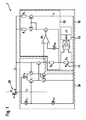
- 電力経路の電流(IE)に対応する電流をもたらす測定経路の電流(IS)を検出するための電流検出装置(10)において、
電流検出装置(10)が、
測定経路に配置された電流測定装置(11)であって、該電流測定装置(11)を通って流れる電流に対応する出力信号を供給するように構成された電流測定装置(11)と;
バイパス電流(IB)を設定するように構成されたバイパス装置(12)と
を備え、
バイパス電流(IB)が、測定電流(IS)の関数として設定され、バイパス装置(12)が前記電流測定装置(11)に並列して配置されている電流検出装置(10)。 - 請求項1に記載の電流検出装置(10)において、
前記バイパス装置(12)が、測定電流(IS)が所定の第1閾値未満となった場合には、バイパス電流が前記バイパス装置(12)を通って流れないように構成されている電流検出装置(10)。 - 請求項1または2に記載の電流検出装置(10)において、
前記バイパス装置(12)が、測定電流(IS)が所定の第2閾値を超えた場合には、前記電流測定装置(11)に並列して前記バイパス電流(IB)を設定するように構成されている電流検出装置(10)。 - 請求項1から3までのいずれか一項に記載の電流検出装置(10)において、
前記バイパス装置(12)が、前記電流測定装置(11)の出力信号の関数として前記バイパス電流(IB)を調整するように構成されている電流検出装置(10)。 - 前記請求項1から4までのいずれか一項に記載の電流検出装置(10)において、
前記バイパス装置(12)が、前記電流測定装置(11)を通る電流を所定の最大限界値に制限するように構成されている電流検出装置(10)。 - 請求項1から5までのいずれか一項に記載の電流検出装置(10)において、
前記バイパス装置(12)が参照電圧源(URef)を含み、該参照電圧源(URef)が、所定の参照電圧を供給するように構成されており、バイパス装置(12)が、電圧信号と、参照電圧源(URef)によって供給された参照電圧とを比較し、比較に応じて、前記電流測定装置(11)に並列してバイパス電流(IB)を設定するように構成されている電流検出装置(10)。 - 請求項6に記載の電流検出装置(10)において、
前記バイパス装置(12)が電流ミラー回路を含み、
前記バイパス装置(12)が、電圧信号と参照電圧との比較に基づいて電流ミラー回路を制御する電流検出装置(10)。 - 電流(IE)を供給するための回路装置(1)において、
電力経路に電流(IE)を供給し、供給された電流(IE)に対応する測定電流(IS)を測定経路に供給するように構成された電流制御装置(20)と;
請求項1から7までのいずれか一項に記載の電流検出装置(10)と
を備える回路装置(1)。 - 請求項8に記載の回路装置(1)において、
前記電流制御装置(20)が、絶縁ゲートバイポーラトランジスタ(IGBT)を含む回路装置(1)。 - 電力経路の電流に対応する電流をもたらす測定経路の電流を検出する方法(100)であって、方法(100)が、
測定経路に電流測定装置(11)を配置するステップ(110)と;
測定経路にバイパス装置(12)を配置するステップ(120)と;
測定経路に流れる電流に応じて、前記電流測定装置(11)に並列してバイパス装置を通って流れる電流(IB)を設定するステップ(130)と;
電流測定装置(11)を通って流れる電流を検出するステップ(140)と
を含む方法(100)。
Applications Claiming Priority (3)
| Application Number | Priority Date | Filing Date | Title |
|---|---|---|---|
| DE102014202634.2A DE102014202634A1 (de) | 2014-02-13 | 2014-02-13 | Stromdetektionseinrichtung und Verfahren zum Erfassen eines elektrischen Stroms |
| DE102014202634.2 | 2014-02-13 | ||
| PCT/EP2014/077946 WO2015120931A1 (de) | 2014-02-13 | 2014-12-16 | Stromdetektionseinrichtung und verfahren zum erfassen eines elektrischen stroms |
Publications (2)
| Publication Number | Publication Date |
|---|---|
| JP2017505914A true JP2017505914A (ja) | 2017-02-23 |
| JP6263272B2 JP6263272B2 (ja) | 2018-01-17 |
Family
ID=52101343
Family Applications (1)
| Application Number | Title | Priority Date | Filing Date |
|---|---|---|---|
| JP2016551285A Active JP6263272B2 (ja) | 2014-02-13 | 2014-12-16 | 電流検出装置および電流を検出する方法 |
Country Status (6)
| Country | Link |
|---|---|
| US (1) | US10031162B2 (ja) |
| JP (1) | JP6263272B2 (ja) |
| KR (1) | KR20160122730A (ja) |
| CN (1) | CN106030319B (ja) |
| DE (1) | DE102014202634A1 (ja) |
| WO (1) | WO2015120931A1 (ja) |
Cited By (1)
| Publication number | Priority date | Publication date | Assignee | Title |
|---|---|---|---|---|
| WO2021085475A1 (ja) * | 2019-11-01 | 2021-05-06 | 国立研究開発法人科学技術振興機構 | 電流センサおよび電力変換回路 |
Families Citing this family (5)
| Publication number | Priority date | Publication date | Assignee | Title |
|---|---|---|---|---|
| DE102014202611A1 (de) * | 2014-02-13 | 2015-08-13 | Robert Bosch Gmbh | Schaltungsanordnung und Verfahren zur Strommessung |
| DE102014202610B4 (de) * | 2014-02-13 | 2025-06-05 | Robert Bosch Gmbh | Stromdetektionseinrichtung und Verfahren zum Erfassen eines elektrischen Stroms |
| DE102018200085A1 (de) * | 2018-01-04 | 2019-07-04 | Robert Bosch Gmbh | Verfahren zum Betreiben einer elektrischen Synchronmaschine |
| DE102021206080A1 (de) | 2021-06-15 | 2022-12-15 | Robert Bosch Gesellschaft mit beschränkter Haftung | Integrierte Schaltung und Verfahren zum Begrenzen eines schaltbaren Laststroms |
| DE102022134423B4 (de) * | 2022-12-21 | 2024-11-14 | Göpel electronic GmbH | Sensorschaltungsanordnung und Niederstromsensor mit Bypasseinheit |
Citations (7)
| Publication number | Priority date | Publication date | Assignee | Title |
|---|---|---|---|---|
| US5200878A (en) * | 1990-07-19 | 1993-04-06 | Fuji Electric Co., Ltd. | Drive circuit for current sense igbt |
| JPH05276761A (ja) * | 1992-03-19 | 1993-10-22 | Hitachi Ltd | パワー半導体素子の過電流検出方法及び回路並びにこれを用いたインバータ装置 |
| JP2003202355A (ja) * | 2002-01-08 | 2003-07-18 | Koyo Seiko Co Ltd | 電流検出回路 |
| JP2004198143A (ja) * | 2002-12-16 | 2004-07-15 | Nissan Motor Co Ltd | 電流検出装置 |
| US20110221424A1 (en) * | 2010-03-12 | 2011-09-15 | Mcnamara Robert | Wide Range Current Sensing |
| JP2012186899A (ja) * | 2011-03-04 | 2012-09-27 | Mitsubishi Electric Corp | パワーモジュール |
| WO2015008461A1 (ja) * | 2013-07-18 | 2015-01-22 | 株式会社デンソー | 半導体素子の電流検出装置 |
Family Cites Families (7)
| Publication number | Priority date | Publication date | Assignee | Title |
|---|---|---|---|---|
| JP3627385B2 (ja) | 1996-06-28 | 2005-03-09 | 株式会社デンソー | 電流検出機能を有する負荷電流供給回路 |
| DE102004059960A1 (de) * | 2004-12-13 | 2006-06-22 | Bourns, Inc., Riverside | Schaltungsanordnung zur Messung eines elektrischen Stromes |
| US7456520B2 (en) * | 2005-03-31 | 2008-11-25 | General Electric Company | Control system, method and product for uninterruptible power supply |
| DE102006029389A1 (de) * | 2006-06-27 | 2008-01-10 | Robert Bosch Gmbh | Verfahren zur Erweiterung der Diagnosefähigkeit von Stromreglern |
| CN101923110B (zh) * | 2009-06-09 | 2012-08-22 | 比亚迪股份有限公司 | 一种检测电路异常电流的方法及装置 |
| US8143880B2 (en) * | 2009-07-31 | 2012-03-27 | Agilent Technologies, Inc. | Dual-range measurement of electrical current |
| US9817039B2 (en) * | 2011-09-29 | 2017-11-14 | Monolithic Power Systems, Inc. | Methods for sensing current in a switching regulator |
-
2014
- 2014-02-13 DE DE102014202634.2A patent/DE102014202634A1/de active Pending
- 2014-12-16 US US15/117,754 patent/US10031162B2/en active Active
- 2014-12-16 JP JP2016551285A patent/JP6263272B2/ja active Active
- 2014-12-16 CN CN201480075452.4A patent/CN106030319B/zh active Active
- 2014-12-16 WO PCT/EP2014/077946 patent/WO2015120931A1/de not_active Ceased
- 2014-12-16 KR KR1020167022157A patent/KR20160122730A/ko not_active Withdrawn
Patent Citations (7)
| Publication number | Priority date | Publication date | Assignee | Title |
|---|---|---|---|---|
| US5200878A (en) * | 1990-07-19 | 1993-04-06 | Fuji Electric Co., Ltd. | Drive circuit for current sense igbt |
| JPH05276761A (ja) * | 1992-03-19 | 1993-10-22 | Hitachi Ltd | パワー半導体素子の過電流検出方法及び回路並びにこれを用いたインバータ装置 |
| JP2003202355A (ja) * | 2002-01-08 | 2003-07-18 | Koyo Seiko Co Ltd | 電流検出回路 |
| JP2004198143A (ja) * | 2002-12-16 | 2004-07-15 | Nissan Motor Co Ltd | 電流検出装置 |
| US20110221424A1 (en) * | 2010-03-12 | 2011-09-15 | Mcnamara Robert | Wide Range Current Sensing |
| JP2012186899A (ja) * | 2011-03-04 | 2012-09-27 | Mitsubishi Electric Corp | パワーモジュール |
| WO2015008461A1 (ja) * | 2013-07-18 | 2015-01-22 | 株式会社デンソー | 半導体素子の電流検出装置 |
Cited By (4)
| Publication number | Priority date | Publication date | Assignee | Title |
|---|---|---|---|---|
| WO2021085475A1 (ja) * | 2019-11-01 | 2021-05-06 | 国立研究開発法人科学技術振興機構 | 電流センサおよび電力変換回路 |
| JPWO2021085475A1 (ja) * | 2019-11-01 | 2021-05-06 | ||
| JP7257712B2 (ja) | 2019-11-01 | 2023-04-14 | 国立研究開発法人科学技術振興機構 | 電流センサおよび電力変換回路 |
| US12095348B2 (en) | 2019-11-01 | 2024-09-17 | Japan Science And Technology Agency | Current sensor and power conversion circuit |
Also Published As
| Publication number | Publication date |
|---|---|
| WO2015120931A1 (de) | 2015-08-20 |
| DE102014202634A1 (de) | 2015-08-13 |
| KR20160122730A (ko) | 2016-10-24 |
| CN106030319B (zh) | 2019-07-23 |
| US20160356817A1 (en) | 2016-12-08 |
| JP6263272B2 (ja) | 2018-01-17 |
| US10031162B2 (en) | 2018-07-24 |
| CN106030319A (zh) | 2016-10-12 |
Similar Documents
| Publication | Publication Date | Title |
|---|---|---|
| JP6263272B2 (ja) | 電流検出装置および電流を検出する方法 | |
| JP5448706B2 (ja) | 電流検出装置及び電流検出方法 | |
| JP5836074B2 (ja) | 温度検出回路及びその調整方法 | |
| US9772369B2 (en) | Precision measurement of voltage drop across a semiconductor switching element | |
| US10247625B2 (en) | Apparatus for correcting of temperature measurement signal | |
| US20080258804A1 (en) | Numerical band gap | |
| JP6151296B2 (ja) | 可変抵抗を用いる広範囲の電流計測 | |
| JP6151295B2 (ja) | デューティサイクリングを用いる広範囲の電流計測 | |
| CN107024294B (zh) | 一种多通道芯片温度测量电路及方法 | |
| US7633386B2 (en) | Amplifier for multi-use of single environmental sensor | |
| US20070103174A1 (en) | Direct current test apparatus | |
| JP5022377B2 (ja) | 測定回路及び試験装置 | |
| JP2015155825A (ja) | 半導体試験装置および半導体装置 | |
| US10634565B2 (en) | Temperature sensing apparatus and temperature sensing method thereof | |
| JP2017106740A (ja) | 異常温度検出回路 | |
| CN105960618B (zh) | 用于检测电流的电流探测装置和方法 | |
| JP5608328B2 (ja) | 定電流回路、及び試験装置 | |
| US9903905B2 (en) | Semiconductor switch and method for determining a current through a semiconductor switch | |
| KR101971245B1 (ko) | Led 모듈 검사용 전류 제어 장치 | |
| US8729964B2 (en) | Power envelope controller and method | |
| JP6271285B2 (ja) | 半導体試験装置 | |
| WO2005116672A1 (ja) | 電源電流測定装置、及び試験装置 | |
| US8519770B2 (en) | Circuit arrangement and input assembly | |
| JP5235128B2 (ja) | 試験システム | |
| JP2018082549A (ja) | スイッチング電源装置 |
Legal Events
| Date | Code | Title | Description |
|---|---|---|---|
| A621 | Written request for application examination |
Free format text: JAPANESE INTERMEDIATE CODE: A621 Effective date: 20160810 |
|
| A131 | Notification of reasons for refusal |
Free format text: JAPANESE INTERMEDIATE CODE: A131 Effective date: 20170621 |
|
| A977 | Report on retrieval |
Free format text: JAPANESE INTERMEDIATE CODE: A971007 Effective date: 20170621 |
|
| A521 | Request for written amendment filed |
Free format text: JAPANESE INTERMEDIATE CODE: A523 Effective date: 20170808 |
|
| TRDD | Decision of grant or rejection written | ||
| A01 | Written decision to grant a patent or to grant a registration (utility model) |
Free format text: JAPANESE INTERMEDIATE CODE: A01 Effective date: 20171117 |
|
| A61 | First payment of annual fees (during grant procedure) |
Free format text: JAPANESE INTERMEDIATE CODE: A61 Effective date: 20171215 |
|
| R150 | Certificate of patent or registration of utility model |
Ref document number: 6263272 Country of ref document: JP Free format text: JAPANESE INTERMEDIATE CODE: R150 |
|
| R250 | Receipt of annual fees |
Free format text: JAPANESE INTERMEDIATE CODE: R250 |
|
| R250 | Receipt of annual fees |
Free format text: JAPANESE INTERMEDIATE CODE: R250 |
|
| R250 | Receipt of annual fees |
Free format text: JAPANESE INTERMEDIATE CODE: R250 |
|
| R250 | Receipt of annual fees |
Free format text: JAPANESE INTERMEDIATE CODE: R250 |
|
| R250 | Receipt of annual fees |
Free format text: JAPANESE INTERMEDIATE CODE: R250 |
|
| R250 | Receipt of annual fees |
Free format text: JAPANESE INTERMEDIATE CODE: R250 |