JP2017508593A - Medical lifting device - Google Patents
Medical lifting device Download PDFInfo
- Publication number
- JP2017508593A JP2017508593A JP2017501078A JP2017501078A JP2017508593A JP 2017508593 A JP2017508593 A JP 2017508593A JP 2017501078 A JP2017501078 A JP 2017501078A JP 2017501078 A JP2017501078 A JP 2017501078A JP 2017508593 A JP2017508593 A JP 2017508593A
- Authority
- JP
- Japan
- Prior art keywords
- strap
- patient
- support
- user
- lifting device
- Prior art date
- Legal status (The legal status is an assumption and is not a legal conclusion. Google has not performed a legal analysis and makes no representation as to the accuracy of the status listed.)
- Pending
Links
- 238000000034 method Methods 0.000 claims abstract description 40
- 230000007246 mechanism Effects 0.000 claims description 39
- 239000000463 material Substances 0.000 claims description 13
- 210000000038 chest Anatomy 0.000 claims description 4
- 230000008569 process Effects 0.000 description 16
- 230000006378 damage Effects 0.000 description 4
- 229920001903 high density polyethylene Polymers 0.000 description 4
- 239000004700 high-density polyethylene Substances 0.000 description 4
- 208000025940 Back injury Diseases 0.000 description 3
- 208000027418 Wounds and injury Diseases 0.000 description 3
- 208000014674 injury Diseases 0.000 description 3
- 229920000742 Cotton Polymers 0.000 description 2
- 239000004677 Nylon Substances 0.000 description 2
- XECAHXYUAAWDEL-UHFFFAOYSA-N acrylonitrile butadiene styrene Chemical compound C=CC=C.C=CC#N.C=CC1=CC=CC=C1 XECAHXYUAAWDEL-UHFFFAOYSA-N 0.000 description 2
- 239000004676 acrylonitrile butadiene styrene Substances 0.000 description 2
- 229920000122 acrylonitrile butadiene styrene Polymers 0.000 description 2
- 238000010586 diagram Methods 0.000 description 2
- 229920001778 nylon Polymers 0.000 description 2
- 239000004033 plastic Substances 0.000 description 2
- 229920003023 plastic Polymers 0.000 description 2
- 208000008035 Back Pain Diseases 0.000 description 1
- 229920000079 Memory foam Polymers 0.000 description 1
- 239000004743 Polypropylene Substances 0.000 description 1
- 238000005452 bending Methods 0.000 description 1
- 238000004891 communication Methods 0.000 description 1
- 230000008878 coupling Effects 0.000 description 1
- 238000010168 coupling process Methods 0.000 description 1
- 238000005859 coupling reaction Methods 0.000 description 1
- 201000010099 disease Diseases 0.000 description 1
- 208000037265 diseases, disorders, signs and symptoms Diseases 0.000 description 1
- 239000004744 fabric Substances 0.000 description 1
- 239000006261 foam material Substances 0.000 description 1
- 230000036541 health Effects 0.000 description 1
- 239000008210 memory foam Substances 0.000 description 1
- 230000003340 mental effect Effects 0.000 description 1
- 230000004048 modification Effects 0.000 description 1
- 238000012986 modification Methods 0.000 description 1
- 210000003205 muscle Anatomy 0.000 description 1
- -1 polypropylene Polymers 0.000 description 1
- 229920001155 polypropylene Polymers 0.000 description 1
- 230000009467 reduction Effects 0.000 description 1
- 239000007779 soft material Substances 0.000 description 1
- 229920002994 synthetic fiber Polymers 0.000 description 1
- 239000012209 synthetic fiber Substances 0.000 description 1
- 229920003002 synthetic resin Polymers 0.000 description 1
- 239000000057 synthetic resin Substances 0.000 description 1
Images





Classifications
-
- A—HUMAN NECESSITIES
- A61—MEDICAL OR VETERINARY SCIENCE; HYGIENE
- A61G—TRANSPORT, PERSONAL CONVEYANCES, OR ACCOMMODATION SPECIALLY ADAPTED FOR PATIENTS OR DISABLED PERSONS; OPERATING TABLES OR CHAIRS; CHAIRS FOR DENTISTRY; FUNERAL DEVICES
- A61G7/00—Beds specially adapted for nursing; Devices for lifting patients or disabled persons
- A61G7/10—Devices for lifting patients or disabled persons, e.g. special adaptations of hoists thereto
- A61G7/1013—Lifting of patients by
- A61G7/1023—Slings used manually
-
- A—HUMAN NECESSITIES
- A61—MEDICAL OR VETERINARY SCIENCE; HYGIENE
- A61G—TRANSPORT, PERSONAL CONVEYANCES, OR ACCOMMODATION SPECIALLY ADAPTED FOR PATIENTS OR DISABLED PERSONS; OPERATING TABLES OR CHAIRS; CHAIRS FOR DENTISTRY; FUNERAL DEVICES
- A61G7/00—Beds specially adapted for nursing; Devices for lifting patients or disabled persons
- A61G7/10—Devices for lifting patients or disabled persons, e.g. special adaptations of hoists thereto
- A61G7/1013—Lifting of patients by
- A61G7/1015—Cables, chains or cords
-
- A—HUMAN NECESSITIES
- A61—MEDICAL OR VETERINARY SCIENCE; HYGIENE
- A61G—TRANSPORT, PERSONAL CONVEYANCES, OR ACCOMMODATION SPECIALLY ADAPTED FOR PATIENTS OR DISABLED PERSONS; OPERATING TABLES OR CHAIRS; CHAIRS FOR DENTISTRY; FUNERAL DEVICES
- A61G7/00—Beds specially adapted for nursing; Devices for lifting patients or disabled persons
- A61G7/10—Devices for lifting patients or disabled persons, e.g. special adaptations of hoists thereto
- A61G7/1038—Manual lifting aids, e.g. frames or racks
-
- A—HUMAN NECESSITIES
- A61—MEDICAL OR VETERINARY SCIENCE; HYGIENE
- A61G—TRANSPORT, PERSONAL CONVEYANCES, OR ACCOMMODATION SPECIALLY ADAPTED FOR PATIENTS OR DISABLED PERSONS; OPERATING TABLES OR CHAIRS; CHAIRS FOR DENTISTRY; FUNERAL DEVICES
- A61G7/00—Beds specially adapted for nursing; Devices for lifting patients or disabled persons
- A61G7/10—Devices for lifting patients or disabled persons, e.g. special adaptations of hoists thereto
- A61G7/1049—Attachment, suspending or supporting means for patients
- A61G7/1051—Flexible harnesses or slings
Landscapes
- Health & Medical Sciences (AREA)
- Nursing (AREA)
- Life Sciences & Earth Sciences (AREA)
- Animal Behavior & Ethology (AREA)
- General Health & Medical Sciences (AREA)
- Public Health (AREA)
- Veterinary Medicine (AREA)
- Invalid Beds And Related Equipment (AREA)
Abstract
【解決手段】 医療用持ち上げ装置および方法が開示される。医療用持ち上げ装置は支持具および少なくとも一つのストラップを含む。前記支持具は患者の背中に対して配置されるようになっている。前記支持部は一対の向かい合う側端部を有する。前記少なくとも一つのストラップは前記支持具の各側端部から伸びる。前記少なくとも一つのストラップは前記装置の使用者が前記使用者の胴部が直立状態で立ったままで前記患者が座位の状態のとき、前記使用者が各ストラップを掴めるように十分な長さを有する。患者を前記支持具によって持ち上げる方法は、患者の背中に対して前記支持具を配置する工程と、前記使用者が直立状態で立ったままで前記患者が座位の状態のとき、各ストラップを掴む工程と、前記患者を立位に持ち上げるため各ストラップを引く工程とを有する。【選択図】 図1A medical lifting apparatus and method are disclosed. The medical lifting device includes a support and at least one strap. The support is arranged with respect to the patient's back. The support has a pair of opposing side ends. The at least one strap extends from each side end of the support. The at least one strap has a length sufficient to allow the user of the device to grip each strap when the patient's torso stands upright and the patient is in a sitting position. . The method of lifting a patient with the support includes the steps of placing the support against the patient's back, and grasping each strap when the user is in a sitting position while the user is standing upright. Pulling each strap to lift the patient in an upright position. [Selection] Figure 1
Description
本発明は、2014年3月17日に提出された米国特許出願第61/954,146号「MEDICAL LIFTING DEVICE(医療用持ち上げ装置)」の優先権を主張するものであり、これはここで参照されることにより本明細書に含まれるものである。 The present invention claims the priority of US Patent Application No. 61 / 954,146, “Medical Lifting Device”, filed March 17, 2014, which is hereby incorporated by reference. Is included in this specification.
本発明は患者の持ち上げの分野に関するものであり、より具体的には、患者を立位まで持ち上げさせる装置および方法に関してである。 The present invention relates to the field of patient lifting, and more specifically to an apparatus and method for lifting a patient to a standing position.
医療の場においては、しばしば医師や看護師などの医療従事者が患者を座位やあおむけの状態から立位に起き上がることを介助する必要がある。従来、医療従事者をこのような「患者移動」において補助する、歩行ベルトなど様々な持ち上げ用具が開発されてきた。しかしながら、これらの現存する用具は患者の精神的快適性および安全性への配慮に欠ける。さらに、近年では、これらの患者移動による医療従事者のけが、特に背部損傷が増加している。よって、患者の快適性および安全性を促進し、および/または医療従事者の持ち上げ中のけがの可能性を最小限に抑えた患者移動を可能とする、よりよい装置が求められている。 In a medical setting, it is often necessary to assist a medical worker such as a doctor or nurse to get a patient up from a sitting or sitting position. Conventionally, various lifting devices such as walking belts have been developed to assist medical staff in such “patient movement”. However, these existing devices lack attention to the patient's mental comfort and safety. Furthermore, in recent years, injuries of medical staff, especially back injury due to these patient movements have increased. Thus, there is a need for a better device that promotes patient comfort and safety and / or allows patient movement with minimal potential for injury while the health care worker is lifting.
本発明の観点は医療用持ち上げ装置および方法に向けられるものである。 An aspect of the present invention is directed to a medical lifting apparatus and method.
本発明の一つの観点によれば、医療用持ち上げ装置が開示される。この医療用持ち上げ装置は一つの支持具および少なくとも一つのストラップを有する。この支持具は患者の背中に対して配置されるようになっている。前記支持具は一対の向かい合う側端部を有する。前記少なくとも一つのストラップは前記支持具の各側端部から伸びるている。前記少なくとも一つのストラップは前記装置の使用者の胴部が直立状態で立っており、かつ前記患者が座っている状態において前記使用者が各ストラップを掴めるような十分な長さを有するものである。背中に対して支持具を配置する工程と、この支持具は一対の向かい合う側端部と各側端部から伸びるストラップを有し、この装置の使用者が直立に立っており、かつ前記患者が座っている状態において前記使用者が各ストラップを掴む工程と、各ストラップを前記患者を立位に持ち上げるために引く工程とを含む。 According to one aspect of the present invention, a medical lifting device is disclosed. The medical lifting device has a support and at least one strap. This support is adapted to be placed against the patient's back. The support has a pair of opposing side ends. The at least one strap extends from each side end of the support. The at least one strap has a length sufficient to allow the user's torso to stand upright and to allow the user to grip each strap while the patient is sitting. . Placing the support against the back, the support having a pair of opposing side ends and a strap extending from each side end, the user of the device standing upright, and the patient The user grasping each strap in a sitting state and pulling each strap to lift the patient in an upright position.
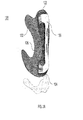
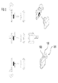
本発明は以下の詳細な説明とそれに付随する図面によって最もよく理解されるものであって、同様の要素は同じ参照番号を有するものである。同様の要素が複数存在する場合、一つの参照番号が特定の要素を参照する小文字表記と共に複数の同様の要素に当てられる。前記要素を集合的に、または非特定の一つまたはそれ以上の要素を参照する場合には、小文字表記は用いられない。慣習に従い、前記図面の様々な機構は特に示されていない限り縮小に従って描かれていない。その反対に、前記様々な機構の寸法は明確性のために拡大されたり縮小されたりするものである。前記図面に含まれるのは以下の図である。
ここで説明される本発明の実施形態は医療従事者によって患者を立位に持ち上げるために使用されることが可能な持ち上げ装置に関するものである。ここで説明される本発明は医療の場に関して説明されているが、ここで説明される持ち上げ装置は人を立位に持ち上げるどのような状況においても使用可能であることが理解されるべきである。 Embodiments of the present invention described herein relate to a lifting device that can be used by a healthcare professional to lift a patient in an upright position. Although the invention described herein has been described with respect to a medical setting, it should be understood that the lifting device described herein can be used in any situation where a person is lifted upright. .
ここで開示される例示的な医療用持ち上げ装置は患者を持ち上げる工程を単純化または容易にするように働くものである。これらの装置は特に、前記患者の持ち上げ中に医療従事者を立位状態または直立状態に保つことを可能にするのに最適であると考えられる。これによって前記医療従事者が前記持ち上げ中にけがをする可能性やその重症度を軽減することが可能である。ここで開示される持ち上げ装置の他の利点は、ここの説明によって当業者に明らかになるはずである。 The exemplary medical lifting device disclosed herein serves to simplify or facilitate the process of lifting a patient. These devices are believed to be particularly optimal for allowing medical personnel to remain in a standing or upright position during the lifting of the patient. This can reduce the likelihood and severity of injury to the medical staff during the lifting. Other advantages of the lifting device disclosed herein will be apparent to those skilled in the art from the description herein.
例えば、ここで開示される持ち上げ装置はいわゆる患者の「抱き上げ」、つまり医療従事者が彼ら自身の力によって座位の患者を抱きかかえ立位にまで持ち上げることを行っている医療従事者に、より人間工学的感触を可能にさせるため使用されることが出来る。抱き上げ中とは異なり、本発明の使用は医療従事者の視線を持ち上げ中にも維持し、それにより患者移動中に重要な前記患者が快適性や信用を感じることを可能にする。ここで開示される持ち上げ装置はまた患者や医療従事者が前記持ち上げ装置に注意を向けることによって両者の注意が逸れる可能性を低減させる。さらに、開示される持ち上げ装置は従来の抱き上げにはない両者間の間隔を提供し、それにより持ち上げ中のより安易な言語コミュニケーションを可能にする。 For example, the lifting device disclosed herein is more human to the so-called “lifting” of the patient, that is, the healthcare worker holding the sitting patient to the standing position by their own force. Can be used to allow an engineering feel. Unlike lifting, the use of the present invention keeps the healthcare worker's line of sight maintained while lifting, thereby allowing the critical patient to feel comfortable and trusted during patient movement. The lifting device disclosed herein also reduces the likelihood that a patient or medical practitioner will be distracted by directing attention to the lifting device. Furthermore, the disclosed lifting device provides a distance between the two that is not found in conventional lifting, thereby allowing easier language communication during lifting.
ここで開示される持ち上げ装置および方法は従来の持ち上げ機構と比較して数々の利点を提供する。特に、ここで開示される装置の使用は従来の抱き上げと比較して医療従事者の脊椎への圧縮荷重を低減する。このような荷重は少なくとも80%低減されることが可能で、よって腰痛やけがのリスクを大幅に減らすものである。さらに、ここで開示される実施形態は、(従来の抱き上げと比較して)前記持ち上げ工程中、前記使用者が用いることが出来る背筋の力または胴部の力を(100%近く)増加させることが可能となるかもしれない。 The lifting apparatus and method disclosed herein provides a number of advantages over conventional lifting mechanisms. In particular, the use of the device disclosed herein reduces the compressive load on the medical staff's spine as compared to conventional lifting. Such a load can be reduced by at least 80%, thus greatly reducing the risk of back pain and injury. Furthermore, embodiments disclosed herein increase (close to 100%) the strength of the back muscles or torso that can be used by the user during the lifting process (compared to conventional lifting). May be possible.
ここで図面を参照すると、図1−6は本発明の観点に沿った医療用持ち上げ装置100を示す。医療用持ち上げ装置100は医療従事者によって患者の立位までの持ち上げを介助するために用いられることが出来る。通常、医療用持ち上げ装置100は支持具120およびストラップ140を含む。医療用持ち上げ装置100の追加の詳細がここで説明される。
Referring now to the drawings, FIGS. 1-6 illustrate a
支持具120は患者の背中に対して配置されるようになっている。支持具120は上端部122、下端部124、および一対の向かい合う側端部126を含む。図1に表されるように、支持具120は好ましくは患者50の腰に対して快適に配置されるように形成および成形される。支持具120は持ち上げ中の患者50の腰の最適な場所に支持を提供するように成形されることも出来る。1つの例示的な実施形態において、支持具120が患者50の背中に対して配置されるとき、支持具120の上端部122は患者背中の胸郭下部にわたって伸び、支持具120の下端部124は患者背中の腰下部にわたって伸びる。さらに、支持具120の側端部126は、図2A−2Bに表されるように、実質的に直線的、またはその上部または下部に沿って伸びる部分が存在してもよいものである。
The
支持具120は、持ち上げ工程中に前記患者の快適性を維持しつつ前記患者に支持を提供する材料によって形成される。1つの例示的な実施形態では、図2Aに示されるように、支持具120は芯部130およびパッド層132を含む。芯部130は患者50の背中をしっかりと支持するよう堅い、非柔軟性の材料により形成される。芯部130は、実質的に支持具120の上端部122から下端部120まで伸びている。図2Aにおいて芯部130はI形を有するよう描写されているが、これに限定されるものではない。例えば、1つの代替的実施形態では、図2Cに示されるように、芯部130はV字形の形状を有する。この実施形態において、V字形芯部130の1つの末端は支持具120の先端部に位置し、このV字形芯部130の先端は支持具120の基底部に位置し、持ち上げ中に前記患者の脊椎に安定性を提供する。芯部130を形成するために使用される好適な材料には、例えば、高密度ポリエチレン(high−density polyethylene:HDPE)などのプラスティックを含む。
The
パッド層132は芯部130および患者50の背中の間に位置し、患者50の快適性を促進するために軟質の材料によって形成される。パッド層132を形成するのに使用する好適な材料には、例えば、天然または合成繊維(綿やナイロンなど)布などがある。パッド層132はさらに、図2Bに表されるように、一またはそれ以上の追加の緩衝層134を含むことが出来る。緩衝層134を形成するのに使用する好適な材料は、例えば、従来の発泡物質である。成形された形状記憶発泡物質が緩衝層134に用いるために特に好ましいと考えられる。
The
図2Bに表されるように、緩衝層134間に割れ目や溝構造が形成されることも可能である。これらの割れ目または溝構造は、好適には支持具120および患者50の間に空気の循環を可能にし、前記患者を持ち上げ中に涼しく快適に保つことが出来る。
As shown in FIG. 2B, a crack or a groove structure can be formed between the buffer layers 134. These cracks or groove structures preferably allow for air circulation between the
ストラップ140は支持具120のどちら側から伸びていてもよい。図1に示されるように、ストラップ140は支持具120の各側端部126から出ている。ストラップ140は、好ましくは支持具120の上端部122または下端部124の位置から支持具120より外側に向けて伸びている。いいかえると、図1に示すように、各ストラップ140の始部142は好ましくは前記患者背中の胸郭下部のすぐそばから伸びて、各ストラップ140の終部144は好ましくは前記患者背中の腰下部のすぐそばから伸びる。
The
ストラップ140は装置100の使用者が胴部が直立状態で立っており前記患者が座位のとき各ストラップ140を掴めるよう十分な長さを有するものである。図1に表されるように、前記使用者は患者50をかがませることなくストラップ140を掴むことが可能である。前記使用者が直立状態の立位でストラップ140を掴むことが可能であることは、前記使用者を前記患者の持ち上げ介助においてより健康的な姿勢に置き、それによって前記患者への背部損傷やその重症化の可能性を減らすことに繋がる。例示的な1つの実施形態では、各ストラップ140は少なくとも支持具120の側端部126からこのストラップの末端まで(つまり、支持具120から最も離れている前記ストラップの部位)、少なくとも17〜29インチ(43.2〜73.7センチメートル)の長さを有する。
The
ストラップ140は耐久性の、柔軟性のある材料によって形成される。ストラップ140を形成するため使用される好ましい材料は、例えば、ナイロン、ポリプロピレン、綿織、および/または伸縮性ウェビングを含む。
The
例えば、図1−2Bのストラップ140の数、サイズ、およびアタッチメントに関する説明および実例は単なる例示であって限定を意図するものではない。特に、追加のストラップ140またはストラップ140の代替的な結合部が本発明の範囲から外れることなく用いられることが出来る。さらに、装置100は上述の構成要素に限定されず、ここの説明より本技術の当業者であれば理解するように、代替的なまたは追加の構成要素を含むことが出来る。
For example, the descriptions and examples relating to the number, size, and attachment of the
装置100はさらに、一対のハンドル部150を含むことが可能である。ハンドル部150は好ましくは持ち上げ工程中に前記患者に彼らの手を置く場所を提供し、患者により促進された快適性、安全性、および、彼らが持ち上げ工程を補助しているという感覚を与えることが可能となるかもしれない。1つの例示的な実施形態において、各ストラップ140は図3A−3Bに示されるようなそれに連結した個々のハンドル部150を含む。ハンドル部150は、持ち上げ中に患者50が掴めるように配置される。前記患者が各ハンドル部を掴み易くするためにハンドル部150はストラップ140の長さ方向に対してストラップ140から内側向きの角度で伸びる。いいかえると、ストラップ140が患者50の前側から離れるように伸びているのに対して、図1および3Aで表されるように、ハンドル部150は好ましくは患者50の前側に平行に伸び、またはストラップ140の伸びる方向に対して直角方向に伸びる。
The
ハンドル150は図2Bでは円筒状で表されるのに対し、本発明はその形状に限定されないことが理解されるべきである。ハンドル部150は前記患者および前記使用者両方が快適でしっかりと握れるような形状にすることが出来る。
It should be understood that while the
また、ハンドル部150は望ましくは装置100の使用者に、より高い安全性を提供する。ハンドル部150は、もし持ち上げ工程中に前記患者が反射的に掴むための場所を提供するように配置される。前記患者は前記使用者(例えば、看護師)の代わりにハンドル部150を掴み、それにより前記患者が前記使用者を引っ張ったり前記使用者の転倒を引き起こす可能性を最小限にして、より安全な持ち上げ環境を提供することになる。前記患者および使用者のハンドル部150はストラップ140によってお互いに取り付けられているため、前記使用者は前記患者から持ち上げ中に蝕知性フィードバックを受け取ることが出来るかもしれない。この蝕知性フィードバック(例、引っ張りや引き寄せの形で)は前記看護師に持ち上げ中の患者の動作に対する反応を可能にさせ、それにより前記使用者にコントロール間隔を、前記患者に安定性を提供することを可能にする。
Also, the
1つの例示的な実施形態では、各ハンドル部150はその上部末端においてストラップ140の始部142に取り付けられ、そしてその末端においてストラップ140の終部144に取り付けられる。または、ハンドル部150の片方または両方の末端は直接支持具120の側端部に取り付けられることも可能である。図3A−3Bに表されるように、各ハンドル部150の上端部は直接側端部126上の突起部に取り付けられる。
In one exemplary embodiment, each handle 150 is attached at its upper end to the beginning 142 of the
別の実施形態では、各ハンドル部150の位置は、ストラップ140の長さに沿って調節可能なものである。ハンドル部150の位置を異なる腕の大きさを持つ患者に合わせるため調節可能にすることが望ましいと考えられる。よって、ハンドル部150はストラップ始部142またはストラップ終部144に、例えば一つまたはそれ以上のスライド部、円形構造、または締め具を介して、可動的に取り付けることも出来る。ここでの説明に基づいて、ハンドル部150を調節可能にストラップ140に取り付けるために好適な構造は当業者に周知のものである。
In another embodiment, the position of each
ハンドル部150はどのような好適な材料によって形成されてもよく、いくつかの実施形態では、それはストラップ140よりも硬い材料となっている。ハンドル部150を形成するのに使用する好適な材料は天然または合成のもので、例えば、高密度ポリエチレン(high−density polyethylene:HDPE)またはアクリロニトリル・ブタジエン・スチレン共重合合成樹脂(acrylonitrile butadiene styrene:ABS)などのどのような好適なプラスティックでもよい。
The
装置100はさらに、一つまたはそれ以上の取り付け機構160を含んでもよい。前記使用者が単純にストラップ140を掴むことを選択する一方で、取り付け機構160は望ましくは持ち上げ工程中、前記使用者と前記患者の間に安全な接続を提供する。一つの例示的な実施形態では、各ストラップ140は、図4に表されるように、それぞれ前記使用者に連結されるように構成された取り付け機構160を含む。持ち上げ工程中前記使用者に連結されると取り付け機構160は患者50の体重の少なくとも一部を担うものである。
The
1つの例示的な実施形態においては、各取り付け機構160は前記使用者によって着用されるベルト162に取り付けられるように構成される。この実施形態において、装置100の取り付け機構160は一つまたはそれ以上のストラップ140の先端部146に配置された輪状構造またはループ状構造を有する。これらの取り付け機構160はベルト162上の対応する取り付け構造164と結合するように構成されている。
In one exemplary embodiment, each
前記使用者162のベルトへ取り付けられる例示的な取り付け機構164は、図5に表される。1つの例示的な実施形態では、取り付け機構164は前記取り付け機構160を装置100に連結するためのフック166を有する。このフック166は取り付け機構164の中に巻き付けられているテザーに取り付けられている。このテザーの長さは、持ち上げ中求められる前記使用者の距離および姿勢を可能にするように、望ましくは前記患者の持ち上げ前に前記使用者によって調節される。取り付け機構は前記テザーの求められる長さを調節し、その後固定するためのラチェット要素を含むことが可能である。
An
取り付け機構164はさらに、取り外し機構168を含むことが可能である。取り外し機構168は、緊急の場合に持ち上げ工程中ストラップ140から取り付け機構164を速やかに取り外すようになっている。例えば、持ち上げ中に前記患者50が倒れたり前記使用者を引き下ろす恐れがある場合、前記使用者は前記使用者から取り付け機構164を外すため取り外し機構168を作動させ、そしてそれによって持ち上げ工程中にストラップ140を取り外すことが可能である。1つの例示的な実施形態では、取り外し機構168は、図5に表されるように取り付け機構の外側にトグルを有する。このトグルは、取り付け機構164内のラチェット機構を解除し、患者50の動きに対応するよう前記テザーを伸ばすように構成されるものである。
The
装置100はさらに、図6に表されるような、格納装置170を含むことが可能である。格納装置170はストラップ140が使用されていないときそれを格納するように支持具120に連結されることが出来る。具体的には、格納装置170はストラップ140を第一の使用状態から第二の待機状態に格納するように構成されるものである。好ましくは、医療用持ち上げ装置100が使用されていないとき格納装置170は自動的にストラップ140を格納するものである。
The
1つの例示的な実施形態において、格納装置170はストラップ140に連結された一つまたはそれ以上の伸縮部材172を有する。この伸縮部材172は(線形またはねじりバネなどの)独立した伸縮要素でもよい。ある特定の好ましい実施形態では、図6に表されるように、伸縮部材172はストラップ140の両方に連結されたねじりバネを有するものである。前記ねじりバネは、ストラップ140に求められる格納のための力を与えるため、支持具120の平面から実質的に直角の面に沿って設置されてもよい。代替的に、または追加的に、ストラップ140は前記格納装置を構成する伸縮部材から少なくとも一部を形成することも出来る。どの形においても、前記伸縮部材は、装置100の使用中に力が加えられていない場合自動的にストラップ140を格納するよう動作するものである。
In one exemplary embodiment, the
格納装置170はまた支持部120に連結する一つまたはそれ以上の滑車を有してもよい。この実施形態において、ストラップ140は滑車の周りを回る。ストラップ140が使用中でない場合前記滑車はストラップ140に前記待機状態へとそれらを格納するよう力を加える。
The
図7は本発明の観点に沿って患者200を持ち上げる1つの例示的な方法を描写している。方法200は医療従事者によって実施されることが出来る。一般に、方法200は対象または患者に支持具を配置する工程と、前記ストラップを掴む工程と、前記ストラップを引く工程とを有する。方法200の工程は以下に医療用持ち上げ装置100の構成要素に関して詳細が説明される。
FIG. 7 depicts one exemplary method for lifting the
工程210において、支持具は患者の背中に対して配置される。1つの例示的な実施形態では、支持具120は患者50の背中に対して配置される。支持具120は一対の向かい合う側端部126、および、各側端部から伸びるストラップ140を有する。上で述べたように、支持具120は好ましくは、持ち上げ中に患者50の腰下部の最適な箇所に支持を提供するように形成されるものである。
In
工程220において、各ストラップは使用者によって掴まれる。前記使用者は立位または直立状態である。1つの実施形態では、ストラップ140は患者50が座位の状態でかつ直立状態で立っている使用者が各ストラップを掴むことが出来るよう十分に長さを有する。
In
工程230において、各ストラップは患者を立位に持ち上げるために引っ張られる。ある実施形態において、前記使用者はストラップ140を引っ張り、それにより支持具120を通して患者50の背中にに持ち上げるための力を加え、そして患者50を立位に持ち上げる。支持具120を患者50の腰下部に対して配置することによって、ストラップ140が引っ張られたとき支持具120は望ましくは上向きの、持ち上げる力を提供する。よって、上で述べたように、ストラップ140は支持具120から支持具120の上端部122および下端部124の位置から外向きに伸びているのである。
In
方法200はここで述べられる工程に限定されるものではなく、ここでの説明によって当業者に理解されるように、代替のまたは追加の工程を含むことが可能である。
上で述べられたように、装置100は一対のハンドル部150を含むことが可能である。この実施形態では、方法200は前記患者が各ストラップに連結するハンドル部を掴むことが出来るような工程を含むことが可能である。ある例示的な実施形態において、患者50は持ち上げ工程中に各ハンドル部を掴むことが可能になっている。これは前記患者に持ち上げ工程中彼らの手を配置する場を提供する。これにより前記患者に彼または彼女に持ち上げ工程を補助しそれにより一定の程度前記持ち上げ工程を補助しているという感覚を与えることが可能であるかもしれない。
As mentioned above, the
装置100はまた一つまたはそれ以上の取り付け機構160を含むことが可能である。この実施形態において、方法200は前記使用者に各ストラップヲ取り付ける工程を含むことが可能である。1つの例示的な実施形態では、ストラップ140は一つまたはそれ以上の取り付け機構160を介して前記使用者によって着用されるベルトに取り付けられる。これらの取り付け機構160は、持ち上げ工程中に前記使用者に連結されたとき患者50の体重の少なくとも一部を担うものである。取り付け機構160がさらに取り外し機構164を含む場合は、方法200はさらに、持ち上げ中に前記使用者から速やかに各ストラップを取り外す工程を含むことが出来る。1つの例示的な実施形態では、前記使用者は、持ち上げ工程中に緊急事が発生したときストラップ140を速やかに取り外せるよう取り外し機構164を作動させることが可能である。
The
装置100はまた格納装置170を含むことが出来る。この実施形態において、方法200は各ストラップを第一の使用状態から第二の待機状態まで格納する工程を含むことが可能である。ある例示的な実施形態では、各ストラップ140を第一の使用状態(つまり、伸びている状態)から、第二の待機状態(つまり、格納状態)まで格納装置170によって格納されることが出来る。望ましくは、格納装置170はストラップ140が前記使用者によって掴まれていない、および/または引っ張られていないとき前記格納状態までストラップ140を自動的に格納するよう操作可能なものである。
The
本発明がここで特定の実施形態を参照して描写および説明されているが、本発明がここに示される詳細に限定されることを意図したものではない。むしろ、本発明からはずれることなく請求の範囲およびその同等の範囲内で詳細に様々な変更が加えられることが可能である。 Although the invention is illustrated and described herein with reference to specific embodiments, it is not intended that the invention be limited to the details shown. Rather, various modifications may be made in the details within the scope of the claims and their equivalents without departing from the invention.
Claims (23)
患者の背中に対して配置されるようになっており、一対の向かい合う側端部を有する支持具と、
前記支持具の側端部から伸びる少なくとも一つのストラップであって、前記装置の使用者が立位状態かつ胴部が直立状態にあり、前記患者が座位状態にあるとき、当該使用者が掴むことが可能であるような十分な長さを有する少なくとも一つのストラップと
を有する、医療用持ち上げ装置。 A medical lifting device,
A support device adapted to be placed against the patient's back and having a pair of opposing side edges;
At least one strap extending from a side edge of the support, grasped by the user of the device when the user is standing and the torso is upright and the patient is in a sitting position; A medical lifting device comprising: at least one strap having a sufficient length such that is possible.
前記支持具に連結された格納装置を有し、前記格納装置は第一の使用状態から第二の待機状態へ前記少なくとも一つのストラップを格納するように構成されるものである、医療用持ち上げ装置。 The medical lifting device of claim 1, further comprising:
A medical lifting device comprising a storage device coupled to the support, the storage device configured to store the at least one strap from a first use state to a second standby state. .
患者の背中に対して支持具を配置する工程であって、前記支持具は一対の向かい合う側端部および前記支持具の各側端部から伸びるストラップを有するものである、前記配置する工程と、
前記使用者が直立状態で立位し、前記患者が座位状態にあるとき、前記使用者が各ストラップを掴む工程と、
前記使用者が前記患者を立位に持ち上げるために各ストラップを引く工程と
を有する、方法。 A method of lifting a patient by a user,
Placing a support against a patient's back, the support having a pair of opposing side ends and a strap extending from each side end of the support; and
When the user stands upright and the patient is in a sitting position, the user grasps each strap;
The user pulling each strap to lift the patient in an upright position.
前記患者が各ストラップに連結されたハンドル部を掴めるようにする工程を有するものである、方法。 The method of claim 17, further comprising:
Allowing the patient to grasp a handle connected to each strap.
前記ストラップ上の一つまたはそれ以上の取り付け機構を通して各ストラップを前記使用者に取り付ける工程を有するものである、方法。 The method of claim 17, further comprising:
Attaching each strap to the user through one or more attachment mechanisms on the strap.
取り外し機構を用いて持ち上げ中、前記使用者から各ストラップを速やかに取り外す工程を有するものである、方法。 The method of claim 19, further comprising:
A method comprising quickly removing each strap from the user during lifting using a removal mechanism.
格納装置を用いて第一の使用状態から第二の待機状態に各ストラップを格納する工程を有するものである、方法。 The method of claim 17, further comprising:
A method comprising storing each strap from a first use state to a second standby state using a storage device.
Applications Claiming Priority (3)
| Application Number | Priority Date | Filing Date | Title |
|---|---|---|---|
| US201461954146P | 2014-03-17 | 2014-03-17 | |
| US61/954,146 | 2014-03-17 | ||
| PCT/US2015/020959 WO2015142845A1 (en) | 2014-03-17 | 2015-03-17 | Medical lifting device |
Publications (1)
| Publication Number | Publication Date |
|---|---|
| JP2017508593A true JP2017508593A (en) | 2017-03-30 |
Family
ID=52774610
Family Applications (1)
| Application Number | Title | Priority Date | Filing Date |
|---|---|---|---|
| JP2017501078A Pending JP2017508593A (en) | 2014-03-17 | 2015-03-17 | Medical lifting device |
Country Status (5)
| Country | Link |
|---|---|
| US (1) | US10517785B2 (en) |
| EP (1) | EP3119367A1 (en) |
| JP (1) | JP2017508593A (en) |
| CA (1) | CA2943094A1 (en) |
| WO (1) | WO2015142845A1 (en) |
Families Citing this family (6)
| Publication number | Priority date | Publication date | Assignee | Title |
|---|---|---|---|---|
| US10517785B2 (en) * | 2014-03-17 | 2019-12-31 | StrongArm Technologies Inc. | Medical lifting device |
| AU2016286285B2 (en) * | 2015-06-30 | 2021-05-13 | Arjohuntleigh Ab | Configurable patient sling |
| EP3479805A4 (en) * | 2016-06-30 | 2020-03-18 | Cho Kee Wong | MANUAL MEDICAL WINCH DEVICE |
| JP6398109B2 (en) * | 2016-09-23 | 2018-10-03 | 株式会社エナジーフロント | Aids such as transfer assistance and standing assistance |
| US11229569B2 (en) | 2020-03-30 | 2022-01-25 | Aleta Edouart-Sorensen | Lifting belt assembly |
| US11704615B2 (en) | 2020-08-31 | 2023-07-18 | altumAI Insurance Solutions, LLC | Risk assessment apparatus and related methods |
Family Cites Families (27)
| Publication number | Priority date | Publication date | Assignee | Title |
|---|---|---|---|---|
| US2350573A (en) * | 1942-06-12 | 1944-06-06 | Smith & Son Inc A | Stretcher |
| US2489828A (en) * | 1944-10-10 | 1949-11-29 | Kenneth F Springer | Litter |
| US3158875A (en) * | 1962-09-05 | 1964-12-01 | Citizens Nat Bank Of Lubbock | Invalid stretcher |
| GB1132572A (en) | 1965-05-20 | 1968-11-06 | Peter Ernest Newman | Improvements relating to child harnesses |
| US4211218A (en) * | 1978-08-14 | 1980-07-08 | Kendrick Richard L | Spinal restraint device |
| GB2195978B (en) * | 1986-08-15 | 1990-01-10 | James Ind Ltd | Lifting sling |
| US4979520A (en) * | 1987-12-21 | 1990-12-25 | Boone Jr Robert L | Pediatric device for immobilizing injured infant utilizing a standard size backboard |
| GB2213734B (en) * | 1987-12-22 | 1992-08-12 | Henry Morgan Hatcher | Lifting aid for incapacitated persons |
| US4922562A (en) * | 1988-07-11 | 1990-05-08 | Western Group International | Rescue pouch |
| SE501679C2 (en) * | 1993-07-21 | 1995-04-10 | Johan Ullman | Stretcher |
| US5396670A (en) * | 1993-10-08 | 1995-03-14 | Guardian Products, Inc. | Sling for a patient lifter |
| US5711044A (en) * | 1995-10-20 | 1998-01-27 | Nu-Way Products, Inc. | Patient transfer assist device |
| US6289534B1 (en) * | 1998-07-31 | 2001-09-18 | Hill-Rom Services, Inc. | Patient lift |
| US6311346B1 (en) * | 1999-03-23 | 2001-11-06 | Heidi Goldman | Transfer belt |
| GB2355248A (en) | 1999-10-16 | 2001-04-18 | Yogen Jayanti Jasani | A lifting and supporting aid |
| US6711762B2 (en) * | 2002-01-30 | 2004-03-30 | Ktk Services, Inc. | Method of using a truck cab bridge bed |
| US6671899B1 (en) * | 2002-06-20 | 2004-01-06 | Jeffrey E. Oja | Person lifting strap |
| US20040025250A1 (en) | 2002-08-12 | 2004-02-12 | Guy Bezalel | Transfer assembly for use by caregivers to lift, support and move the elderly or infirm |
| JP2009515560A (en) * | 2005-03-14 | 2009-04-16 | エルゴ アシスト テクノロジー リミテッド ライアビリティ カンパニー | Patient movement system with associated frame and lift cart |
| US20070278263A1 (en) | 2006-06-06 | 2007-12-06 | Zak David F | Emergency egress carrier for child or pet |
| US7708019B2 (en) * | 2006-06-09 | 2010-05-04 | Kendrick Ems, Inc. | Spinal restraint device |
| US7627912B1 (en) | 2008-09-08 | 2009-12-08 | Mckinney Thomas Wade | Portable patient transfer system |
| US8800076B2 (en) * | 2010-07-19 | 2014-08-12 | Bryan Jeffrey Ophaug | Spring retractable transfer belt apparatus |
| WO2012128802A1 (en) | 2011-03-23 | 2012-09-27 | Kci Licensing, Inc. | Patient support for handling and transfers |
| CA2870094C (en) | 2012-04-12 | 2018-03-13 | Sage Products, Llc | Apparatus and method for positioning a seated patient |
| US10517785B2 (en) * | 2014-03-17 | 2019-12-31 | StrongArm Technologies Inc. | Medical lifting device |
| US20160015584A1 (en) * | 2014-07-18 | 2016-01-21 | Concepto Llc | Gait belt |
-
2015
- 2015-03-17 US US15/127,148 patent/US10517785B2/en active Active
- 2015-03-17 EP EP15713121.0A patent/EP3119367A1/en not_active Withdrawn
- 2015-03-17 JP JP2017501078A patent/JP2017508593A/en active Pending
- 2015-03-17 WO PCT/US2015/020959 patent/WO2015142845A1/en not_active Ceased
- 2015-03-17 CA CA2943094A patent/CA2943094A1/en not_active Abandoned
Also Published As
| Publication number | Publication date |
|---|---|
| CA2943094A1 (en) | 2015-09-24 |
| US20170181910A1 (en) | 2017-06-29 |
| WO2015142845A1 (en) | 2015-09-24 |
| US10517785B2 (en) | 2019-12-31 |
| EP3119367A1 (en) | 2017-01-25 |
Similar Documents
| Publication | Publication Date | Title |
|---|---|---|
| US7846080B2 (en) | Machine and method for head, neck and, shoulder stretching | |
| US10398585B2 (en) | Shoulder and arm restraint | |
| US10517785B2 (en) | Medical lifting device | |
| US9721545B2 (en) | Carrying device for a wind instrument | |
| BR112012021211A2 (en) | Highly adjustable lumbar strap. | |
| US7627912B1 (en) | Portable patient transfer system | |
| US10258523B2 (en) | Patient turning apparatus and methods for use | |
| WO2012128802A1 (en) | Patient support for handling and transfers | |
| CN204181760U (en) | Cervical vertebra tractor | |
| US20120019015A1 (en) | Lift assist device | |
| US8845565B1 (en) | Arm sling neck cushion kit | |
| US5449004A (en) | Birthing gown | |
| CN201312858Y (en) | An emergency stretcher | |
| JP6403275B2 (en) | Cervical spine orthosis and cervical spine orthosis unit | |
| CN103976809B (en) | A kind of lower maxillary luxation reset strap | |
| CN104224454B (en) | A kind of patient carries blanket | |
| US20130106077A1 (en) | Wheelchair pull strap | |
| CN204147186U (en) | Novel litter | |
| CN217448174U (en) | Adjustable cervical vertebra fixing device | |
| KR102760833B1 (en) | Full body vacuum mattress | |
| US20090277464A1 (en) | Gravity Aided Restraint | |
| CN213851321U (en) | A sling for external fixation of the hand after surgery | |
| CN207640634U (en) | Orthopaedics supports walking aid device | |
| CN211243963U (en) | Upper limb nursing fixing support | |
| JP3166231U (en) | Auxiliary belt for patient movement |