JP2017508982A - 運動する構成部材のストロークを検出するためのセンサ装置 - Google Patents
運動する構成部材のストロークを検出するためのセンサ装置 Download PDFInfo
- Publication number
- JP2017508982A JP2017508982A JP2016559254A JP2016559254A JP2017508982A JP 2017508982 A JP2017508982 A JP 2017508982A JP 2016559254 A JP2016559254 A JP 2016559254A JP 2016559254 A JP2016559254 A JP 2016559254A JP 2017508982 A JP2017508982 A JP 2017508982A
- Authority
- JP
- Japan
- Prior art keywords
- sensing
- magnet
- measuring element
- magnetic field
- sensor device
- Prior art date
- Legal status (The legal status is an assumption and is not a legal conclusion. Google has not performed a legal analysis and makes no representation as to the accuracy of the status listed.)
- Granted
Links
Images




Classifications
-
- G—PHYSICS
- G01—MEASURING; TESTING
- G01D—MEASURING NOT SPECIALLY ADAPTED FOR A SPECIFIC VARIABLE; ARRANGEMENTS FOR MEASURING TWO OR MORE VARIABLES NOT COVERED IN A SINGLE OTHER SUBCLASS; TARIFF METERING APPARATUS; MEASURING OR TESTING NOT OTHERWISE PROVIDED FOR
- G01D5/00—Mechanical means for transferring the output of a sensing member; Means for converting the output of a sensing member to another variable where the form or nature of the sensing member does not constrain the means for converting; Transducers not specially adapted for a specific variable
- G01D5/12—Mechanical means for transferring the output of a sensing member; Means for converting the output of a sensing member to another variable where the form or nature of the sensing member does not constrain the means for converting; Transducers not specially adapted for a specific variable using electric or magnetic means
- G01D5/14—Mechanical means for transferring the output of a sensing member; Means for converting the output of a sensing member to another variable where the form or nature of the sensing member does not constrain the means for converting; Transducers not specially adapted for a specific variable using electric or magnetic means influencing the magnitude of a current or voltage
- G01D5/142—Mechanical means for transferring the output of a sensing member; Means for converting the output of a sensing member to another variable where the form or nature of the sensing member does not constrain the means for converting; Transducers not specially adapted for a specific variable using electric or magnetic means influencing the magnitude of a current or voltage using Hall-effect devices
- G01D5/145—Mechanical means for transferring the output of a sensing member; Means for converting the output of a sensing member to another variable where the form or nature of the sensing member does not constrain the means for converting; Transducers not specially adapted for a specific variable using electric or magnetic means influencing the magnitude of a current or voltage using Hall-effect devices influenced by the relative movement between the Hall device and magnetic fields
-
- G—PHYSICS
- G01—MEASURING; TESTING
- G01D—MEASURING NOT SPECIALLY ADAPTED FOR A SPECIFIC VARIABLE; ARRANGEMENTS FOR MEASURING TWO OR MORE VARIABLES NOT COVERED IN A SINGLE OTHER SUBCLASS; TARIFF METERING APPARATUS; MEASURING OR TESTING NOT OTHERWISE PROVIDED FOR
- G01D5/00—Mechanical means for transferring the output of a sensing member; Means for converting the output of a sensing member to another variable where the form or nature of the sensing member does not constrain the means for converting; Transducers not specially adapted for a specific variable
- G01D5/12—Mechanical means for transferring the output of a sensing member; Means for converting the output of a sensing member to another variable where the form or nature of the sensing member does not constrain the means for converting; Transducers not specially adapted for a specific variable using electric or magnetic means
- G01D5/14—Mechanical means for transferring the output of a sensing member; Means for converting the output of a sensing member to another variable where the form or nature of the sensing member does not constrain the means for converting; Transducers not specially adapted for a specific variable using electric or magnetic means influencing the magnitude of a current or voltage
- G01D5/142—Mechanical means for transferring the output of a sensing member; Means for converting the output of a sensing member to another variable where the form or nature of the sensing member does not constrain the means for converting; Transducers not specially adapted for a specific variable using electric or magnetic means influencing the magnitude of a current or voltage using Hall-effect devices
- G01D5/147—Mechanical means for transferring the output of a sensing member; Means for converting the output of a sensing member to another variable where the form or nature of the sensing member does not constrain the means for converting; Transducers not specially adapted for a specific variable using electric or magnetic means influencing the magnitude of a current or voltage using Hall-effect devices influenced by the movement of a third element, the position of Hall device and the source of magnetic field being fixed in respect to each other
Landscapes
- Physics & Mathematics (AREA)
- General Physics & Mathematics (AREA)
- Transmission And Conversion Of Sensor Element Output (AREA)
- Measurement Of Length, Angles, Or The Like Using Electric Or Magnetic Means (AREA)
Abstract
Description
これに対して、独立請求項1に記載の特徴を有する、運動する構成部材のストロークを検出するためのセンサ装置は、少なくとも一つの小さく低コストの磁石が、適用される装置の定置の部分又はセンサハウジング内に配置され、しかも例えば検知測定素子の直近に配置されるという利点を有する。適用される装置の定置の部分に設けられる位置固定の磁気回路は、一つ又は複数の小さい磁石を有することができる。さらには、検知測定範囲と、少なくとも一つの位置固定の磁石を備える定置のクランプ範囲とからなる広い測定範囲を、従来のように可動の部分に設けられた二つの格段に長い磁石によって実現するのではなく、適用される装置の可動の部分に設けられた少なくとも一つのより小さな、ひいてはより低コストの磁石によって実現することが可能となる。従来の磁石よりも小さな構造スペースしか必要としない比較的小さな磁石を可動の部分に組み込むことができるので、少なくとも一つの有効磁石の組み込みを有利にも容易にすることができる。少なくとも一つの定置の磁石は、支持磁石として機能し、同様にして非常に小さく低コストに設計することができる。なぜなら、この少なくとも一つの定置の磁石は、検知測定素子の極めて近傍に取り付けることができるからである。検知測定素子が回路基板に取り付けられている場合には、支持磁石も同様にしてこの回路基板上に、例えば検知測定素子に隣接して配置することができるか、又は、例えば回路基板の、検知測定素子とは反対の側に配置することができる。本発明の実施形態は、例えばホールセンサ、特にいわゆる2D若しくは3Dホールセンサ、又は、例えばAMRセンサ若しくはGMRセンサのようなxMRセンサ等といった、磁束密度の方向の変化を評価する総てのストロークセンサ及び/又は角度センサにおいて使用可能である。特に二つ又は三つの空間方向における磁束密度を測定する検知測定素子は、複数の磁石の磁化方向を組み合わせることと、少なくとも一つの有効磁石に対する少なくとも一つの支持磁石の配置とによって、例えば少なくとも一つの磁束コンセントレータを備える3Dホールセンサのような検知測定素子の要求を満たす多くの可能性を提供する。
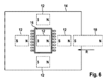
図1及び図2から見て取れるように、運動する構成部材5のストロークを検出するための本発明に係るセンサ装置1の図示された実施例は、磁気測定装置10を含む。磁気測定装置10の磁界の少なくとも一つの空間的な成分は、検出すべきストロークRにわたる構成部材5の運動によって変化し、これによって、位置固定の検知測定素子16.1に対する、運動する構成部材5の位置を検出することが可能である。本発明によれば、運動する構成部材5に結合された少なくとも一つの有効磁石18と、検知測定素子16.1の測定範囲内に位置固定的に配置された少なくとも一つの支持磁石12とが、磁界を形成する。
Claims (10)
- 運動する構成部材(5)のストロークを検出するためのセンサ装置であって、
磁気測定装置(10)の磁界の少なくとも一つの空間的な成分が、検出すべきストローク(R)にわたる前記構成部材(5)の運動によって変化し、これによって、位置固定の検知測定素子(16.1)に対する、運動する前記構成部材(5)の位置を検出することが可能である、
センサ装置において、
運動する前記構成部材(5)に結合された少なくとも一つの有効磁石(18)と、前記検知測定素子(16.1)の測定範囲内に位置固定的に配置された少なくとも一つの支持磁石(12)とが、前記磁界を形成する、
ことを特徴とするセンサ装置。 - 少なくとも一つの定置の前記支持磁石(12)は、前記検知測定素子(16.1)の位置において、一定の定置の第1磁界ベクトルを形成する、
請求項1記載のセンサ装置。 - 少なくとも一つの定置の前記支持磁石(12)の一定の定置の前記第1磁界ベクトルは、前記検知測定素子(16.1)の位置において、前記検知測定素子(16.1)の測定面の法線に対して予め定められた角度を有する、
請求項2記載のセンサ装置。 - 少なくとも一つの可動の前記有効磁石(18)は、前記検知測定素子(16.1)の前記測定範囲内に入ると、前記検知測定素子(16.1)の位置において回転する第2磁界ベクトルを形成し、前記第2磁界ベクトルの磁界は、少なくとも一つの前記支持磁石(12)の前記磁界に重畳する、
請求項1乃至3のいずれか一項記載のセンサ装置。 - 少なくとも一つの前記有効磁石(18)の磁化と、少なくとも一つの前記支持磁石(12)の磁化とは、互いに予め定められた角度を有する、
請求項1乃至4のいずれか一項記載のセンサ装置。 - 前記検知測定素子(16.1)は、第1表面(14.1)及び第2表面(14.2)を有する回路基板(14)上に配置されている、
請求項1乃至5のいずれか一項記載のセンサ装置。 - 少なくとも一つの定置の前記支持磁石(12)は、前記検知測定素子(16.1)に隣接して前記回路基板(14)の同一の表面(14.1)上に配置されている、又は、前記検知測定素子(16.1)の下に若しくは前記検知測定素子に隣接して前記回路基板(14)の他方の表面(14.2)上に配置されている、又は、前記回路基板(14)の貫通孔内に配置されている、
請求項6記載のセンサ装置。 - 少なくとも一つの定置の前記支持磁石(12)は、強磁性の磁束導体片と共に取り付けられている、
請求項6又は7記載のセンサ装置。 - 前記検知測定素子(16.1)は、評価モジュール(16)の一部として構成されている、
請求項1乃至8のいずれか一項記載のセンサ装置。 - 前記検出すべきストローク(R)は、並進運動又は回転運動を表す、
請求項1乃至9のいずれか一項記載のセンサ装置。
Applications Claiming Priority (3)
| Application Number | Priority Date | Filing Date | Title |
|---|---|---|---|
| DE102014205566.0A DE102014205566A1 (de) | 2014-03-26 | 2014-03-26 | Sensoranordnung zur Wegerfassung an einem bewegten Bauteil |
| DE102014205566.0 | 2014-03-26 | ||
| PCT/EP2015/053902 WO2015144377A1 (de) | 2014-03-26 | 2015-02-25 | Sensoranordnung zur wegerfassung an einem bewegten bauteil |
Publications (2)
| Publication Number | Publication Date |
|---|---|
| JP2017508982A true JP2017508982A (ja) | 2017-03-30 |
| JP6534682B2 JP6534682B2 (ja) | 2019-06-26 |
Family
ID=52633246
Family Applications (1)
| Application Number | Title | Priority Date | Filing Date |
|---|---|---|---|
| JP2016559254A Expired - Fee Related JP6534682B2 (ja) | 2014-03-26 | 2015-02-25 | 運動する構成部材のストロークを検出するためのセンサ装置 |
Country Status (6)
| Country | Link |
|---|---|
| US (1) | US9927260B2 (ja) |
| EP (1) | EP3123117A1 (ja) |
| JP (1) | JP6534682B2 (ja) |
| CN (1) | CN106164621B (ja) |
| DE (1) | DE102014205566A1 (ja) |
| WO (1) | WO2015144377A1 (ja) |
Cited By (1)
| Publication number | Priority date | Publication date | Assignee | Title |
|---|---|---|---|---|
| JP2021529972A (ja) * | 2018-07-18 | 2021-11-04 | アーファウエル リスト ゲゼルシャフト ミット ベシュレンクテル ハフツング | 流量測定機器用の圧力差検出器および流量測定機器 |
Families Citing this family (5)
| Publication number | Priority date | Publication date | Assignee | Title |
|---|---|---|---|---|
| US11647678B2 (en) | 2016-08-23 | 2023-05-09 | Analog Devices International Unlimited Company | Compact integrated device packages |
| US10697800B2 (en) * | 2016-11-04 | 2020-06-30 | Analog Devices Global | Multi-dimensional measurement using magnetic sensors and related systems, methods, and integrated circuits |
| DE102017222674A1 (de) * | 2016-12-29 | 2018-07-05 | Robert Bosch Gmbh | Wegsensor |
| DE102019200183A1 (de) | 2018-01-15 | 2019-07-18 | Continental Teves Ag & Co. Ohg | Verfahren zur Wegerfassung, Wegerfassungsanordnung und Bremssystem |
| US11628275B2 (en) | 2018-01-31 | 2023-04-18 | Analog Devices, Inc. | Electronic devices |
Citations (9)
| Publication number | Priority date | Publication date | Assignee | Title |
|---|---|---|---|---|
| JPS50110255U (ja) * | 1974-02-18 | 1975-09-09 | ||
| JPH11514747A (ja) * | 1996-08-24 | 1999-12-14 | ローベルト ボツシユ ゲゼルシヤフト ミツト ベシユレンクテル ハフツング | 回転角を無接触で検出するための測定装置 |
| JP2007024738A (ja) * | 2005-07-20 | 2007-02-01 | Tomen Electronics Corp | 回転角度検出装置 |
| US20090278711A1 (en) * | 2006-08-01 | 2009-11-12 | Continental Teves Ag & Co. Ohg | Sensor Arrangement for the Precise Detection of Relative Movements Between An Encoder and A Sensor |
| JP2010197399A (ja) * | 2010-04-01 | 2010-09-09 | Mitsubishi Electric Corp | 磁界検出装置およびそれを調整する方法 |
| JP2012247298A (ja) * | 2011-05-27 | 2012-12-13 | Panasonic Corp | 位置検出装置 |
| JP2013083516A (ja) * | 2011-10-07 | 2013-05-09 | Bosch Corp | 位置検出センサ、これを備えたクラッチアクチュエータ、およびこれを備えたクラッチ装置 |
| JP2013096723A (ja) * | 2011-10-28 | 2013-05-20 | Denso Corp | 位置検出装置 |
| WO2013127984A1 (en) * | 2012-03-01 | 2013-09-06 | Tyco Electronics Amp Gmbh | Method for contactlessly measuring a relative position by means of a 3d hall sensor having measurement signal store |
Family Cites Families (7)
| Publication number | Priority date | Publication date | Assignee | Title |
|---|---|---|---|---|
| ES2176312T3 (es) | 1993-12-22 | 2002-12-01 | Continental Teves Ag & Co Ohg | Dispositivo para detectar movimientos de giro o angulares. |
| JP3855801B2 (ja) * | 2001-03-27 | 2006-12-13 | 株式会社デンソー | 回転検出装置 |
| JP3655897B2 (ja) * | 2002-08-07 | 2005-06-02 | 三菱電機株式会社 | 磁気検出装置 |
| US20070229058A1 (en) * | 2006-03-31 | 2007-10-04 | Wolf Ronald J | Displacement sensor |
| DE102007038395A1 (de) * | 2007-08-14 | 2009-02-19 | Robert Bosch Gmbh | Wegsensor |
| DE202009018762U1 (de) * | 2009-09-26 | 2013-02-27 | Brose Fahrzeugteile Gmbh & Co. Kommanditgesellschaft, Hallstadt | Vorrichtung zur Erfassung der Drehzahl und/oder der Drehrichtung eines Drehantriebs eines Kraftfahrzeugs |
| DE102009055104A1 (de) | 2009-12-21 | 2011-06-22 | Robert Bosch GmbH, 70469 | Magnetfeldsensoranordnung zur Wegerfassung an beweglichen Bauteilen |
-
2014
- 2014-03-26 DE DE102014205566.0A patent/DE102014205566A1/de active Pending
-
2015
- 2015-02-25 CN CN201580016350.XA patent/CN106164621B/zh not_active Expired - Fee Related
- 2015-02-25 WO PCT/EP2015/053902 patent/WO2015144377A1/de not_active Ceased
- 2015-02-25 EP EP15708771.9A patent/EP3123117A1/de not_active Ceased
- 2015-02-25 JP JP2016559254A patent/JP6534682B2/ja not_active Expired - Fee Related
- 2015-02-25 US US15/128,791 patent/US9927260B2/en active Active
Patent Citations (9)
| Publication number | Priority date | Publication date | Assignee | Title |
|---|---|---|---|---|
| JPS50110255U (ja) * | 1974-02-18 | 1975-09-09 | ||
| JPH11514747A (ja) * | 1996-08-24 | 1999-12-14 | ローベルト ボツシユ ゲゼルシヤフト ミツト ベシユレンクテル ハフツング | 回転角を無接触で検出するための測定装置 |
| JP2007024738A (ja) * | 2005-07-20 | 2007-02-01 | Tomen Electronics Corp | 回転角度検出装置 |
| US20090278711A1 (en) * | 2006-08-01 | 2009-11-12 | Continental Teves Ag & Co. Ohg | Sensor Arrangement for the Precise Detection of Relative Movements Between An Encoder and A Sensor |
| JP2010197399A (ja) * | 2010-04-01 | 2010-09-09 | Mitsubishi Electric Corp | 磁界検出装置およびそれを調整する方法 |
| JP2012247298A (ja) * | 2011-05-27 | 2012-12-13 | Panasonic Corp | 位置検出装置 |
| JP2013083516A (ja) * | 2011-10-07 | 2013-05-09 | Bosch Corp | 位置検出センサ、これを備えたクラッチアクチュエータ、およびこれを備えたクラッチ装置 |
| JP2013096723A (ja) * | 2011-10-28 | 2013-05-20 | Denso Corp | 位置検出装置 |
| WO2013127984A1 (en) * | 2012-03-01 | 2013-09-06 | Tyco Electronics Amp Gmbh | Method for contactlessly measuring a relative position by means of a 3d hall sensor having measurement signal store |
Cited By (2)
| Publication number | Priority date | Publication date | Assignee | Title |
|---|---|---|---|---|
| JP2021529972A (ja) * | 2018-07-18 | 2021-11-04 | アーファウエル リスト ゲゼルシャフト ミット ベシュレンクテル ハフツング | 流量測定機器用の圧力差検出器および流量測定機器 |
| JP7339326B2 (ja) | 2018-07-18 | 2023-09-05 | アーファウエル リスト ゲゼルシャフト ミット ベシュレンクテル ハフツング | 流量測定機器用の圧力差検出器および流量測定機器 |
Also Published As
| Publication number | Publication date |
|---|---|
| JP6534682B2 (ja) | 2019-06-26 |
| EP3123117A1 (de) | 2017-02-01 |
| CN106164621A (zh) | 2016-11-23 |
| US9927260B2 (en) | 2018-03-27 |
| WO2015144377A1 (de) | 2015-10-01 |
| CN106164621B (zh) | 2019-03-12 |
| US20170108354A1 (en) | 2017-04-20 |
| DE102014205566A1 (de) | 2015-10-01 |
Similar Documents
| Publication | Publication Date | Title |
|---|---|---|
| CN102686980B (zh) | 用于检测运动元件位移的磁场传感器装置 | |
| JP2017508982A (ja) | 運動する構成部材のストロークを検出するためのセンサ装置 | |
| US9347799B2 (en) | Magnetic field sensor system with a magnetic wheel rotatable around a wheel axis and with magnetic sensor elements being arranged within a plane perpendicular to the wheel axis | |
| JP2015537207A (ja) | 可動構成部材の動きを検出する磁気的測定装置及び対応するセンサ装置 | |
| JP6049570B2 (ja) | 回転検出装置 | |
| US8531181B2 (en) | Magnetic linear sensor arrangement | |
| JP2015525891A (ja) | 回転運動する構成部材の回転角度を検出するためのセンサ装置 | |
| CN104279205B (zh) | 活塞缸装置、尤其是用于机动车辆中的分离系统的活塞缸装置 | |
| US9709422B2 (en) | Rotation angle and stroke amount detection device | |
| JP2009069148A (ja) | 磁界を測定する測定装置 | |
| EP2657651A3 (en) | Position sensor | |
| CN113272627A (zh) | 用于长行程线性永磁电机的位置传感器 | |
| KR102656404B1 (ko) | Gmr-센서에 대한 자석의 위치를 조정하기 위한 방법 및 장치 | |
| JP2007163475A (ja) | 直線的な移動に制限された移動体用の磁力式位置センサ | |
| CA2283209C (en) | Device for detecting the position of a moveable magnet for generating a magnetic field | |
| JP2023037247A (ja) | ストロークセンサと、これを用いた自動車のブレーキシステム及びステアリングシステム | |
| AU757212B2 (en) | Magnetic position sensor | |
| US9442169B2 (en) | Measuring system | |
| JP2018004315A (ja) | 位置センサ | |
| JP2016536581A (ja) | 車両内のペダル運動を検出するセンサ装置 | |
| US20080297145A1 (en) | Increasing the working gap in a magnetic sensor with an auxiliary field | |
| US11085796B2 (en) | Sensor device | |
| JP2013524252A5 (ja) | ||
| JPH11281308A (ja) | 位置検知装置 | |
| JP5679453B2 (ja) | 変位検出装置 |
Legal Events
| Date | Code | Title | Description |
|---|---|---|---|
| A621 | Written request for application examination |
Free format text: JAPANESE INTERMEDIATE CODE: A621 Effective date: 20160926 |
|
| A977 | Report on retrieval |
Free format text: JAPANESE INTERMEDIATE CODE: A971007 Effective date: 20170828 |
|
| A131 | Notification of reasons for refusal |
Free format text: JAPANESE INTERMEDIATE CODE: A131 Effective date: 20170904 |
|
| A521 | Request for written amendment filed |
Free format text: JAPANESE INTERMEDIATE CODE: A523 Effective date: 20171201 |
|
| A131 | Notification of reasons for refusal |
Free format text: JAPANESE INTERMEDIATE CODE: A131 Effective date: 20180604 |
|
| A601 | Written request for extension of time |
Free format text: JAPANESE INTERMEDIATE CODE: A601 Effective date: 20180904 |
|
| TRDD | Decision of grant or rejection written | ||
| A01 | Written decision to grant a patent or to grant a registration (utility model) |
Free format text: JAPANESE INTERMEDIATE CODE: A01 Effective date: 20190508 |
|
| A61 | First payment of annual fees (during grant procedure) |
Free format text: JAPANESE INTERMEDIATE CODE: A61 Effective date: 20190529 |
|
| R150 | Certificate of patent or registration of utility model |
Ref document number: 6534682 Country of ref document: JP Free format text: JAPANESE INTERMEDIATE CODE: R150 |
|
| R250 | Receipt of annual fees |
Free format text: JAPANESE INTERMEDIATE CODE: R250 |
|
| LAPS | Cancellation because of no payment of annual fees |