JP2017509105A - Electroluminescence device with short circuit detection circuit - Google Patents
Electroluminescence device with short circuit detection circuit Download PDFInfo
- Publication number
- JP2017509105A JP2017509105A JP2016545784A JP2016545784A JP2017509105A JP 2017509105 A JP2017509105 A JP 2017509105A JP 2016545784 A JP2016545784 A JP 2016545784A JP 2016545784 A JP2016545784 A JP 2016545784A JP 2017509105 A JP2017509105 A JP 2017509105A
- Authority
- JP
- Japan
- Prior art keywords
- light emitting
- emitting element
- short circuit
- voltage
- unit
- Prior art date
- Legal status (The legal status is an assumption and is not a legal conclusion. Google has not performed a legal analysis and makes no representation as to the accuracy of the status listed.)
- Granted
Links
Images



Classifications
-
- G—PHYSICS
- G01—MEASURING; TESTING
- G01R—MEASURING ELECTRIC VARIABLES; MEASURING MAGNETIC VARIABLES
- G01R31/00—Arrangements for testing electric properties; Arrangements for locating electric faults; Arrangements for electrical testing characterised by what is being tested not provided for elsewhere
- G01R31/26—Testing of individual semiconductor devices
-
- H—ELECTRICITY
- H05—ELECTRIC TECHNIQUES NOT OTHERWISE PROVIDED FOR
- H05B—ELECTRIC HEATING; ELECTRIC LIGHT SOURCES NOT OTHERWISE PROVIDED FOR; CIRCUIT ARRANGEMENTS FOR ELECTRIC LIGHT SOURCES, IN GENERAL
- H05B45/00—Circuit arrangements for operating light-emitting diodes [LED]
- H05B45/60—Circuit arrangements for operating LEDs comprising organic material, e.g. for operating organic light-emitting diodes [OLED] or polymer light-emitting diodes [PLED]
-
- H—ELECTRICITY
- H05—ELECTRIC TECHNIQUES NOT OTHERWISE PROVIDED FOR
- H05B—ELECTRIC HEATING; ELECTRIC LIGHT SOURCES NOT OTHERWISE PROVIDED FOR; CIRCUIT ARRANGEMENTS FOR ELECTRIC LIGHT SOURCES, IN GENERAL
- H05B45/00—Circuit arrangements for operating light-emitting diodes [LED]
- H05B45/10—Controlling the intensity of the light
-
- H—ELECTRICITY
- H05—ELECTRIC TECHNIQUES NOT OTHERWISE PROVIDED FOR
- H05B—ELECTRIC HEATING; ELECTRIC LIGHT SOURCES NOT OTHERWISE PROVIDED FOR; CIRCUIT ARRANGEMENTS FOR ELECTRIC LIGHT SOURCES, IN GENERAL
- H05B45/00—Circuit arrangements for operating light-emitting diodes [LED]
- H05B45/30—Driver circuits
- H05B45/37—Converter circuits
- H05B45/3725—Switched mode power supply [SMPS]
- H05B45/375—Switched mode power supply [SMPS] using buck topology
-
- H—ELECTRICITY
- H05—ELECTRIC TECHNIQUES NOT OTHERWISE PROVIDED FOR
- H05B—ELECTRIC HEATING; ELECTRIC LIGHT SOURCES NOT OTHERWISE PROVIDED FOR; CIRCUIT ARRANGEMENTS FOR ELECTRIC LIGHT SOURCES, IN GENERAL
- H05B45/00—Circuit arrangements for operating light-emitting diodes [LED]
- H05B45/40—Details of LED load circuits
- H05B45/44—Details of LED load circuits with an active control inside an LED matrix
- H05B45/48—Details of LED load circuits with an active control inside an LED matrix having LEDs organised in strings and incorporating parallel shunting devices
-
- H—ELECTRICITY
- H05—ELECTRIC TECHNIQUES NOT OTHERWISE PROVIDED FOR
- H05B—ELECTRIC HEATING; ELECTRIC LIGHT SOURCES NOT OTHERWISE PROVIDED FOR; CIRCUIT ARRANGEMENTS FOR ELECTRIC LIGHT SOURCES, IN GENERAL
- H05B45/00—Circuit arrangements for operating light-emitting diodes [LED]
- H05B45/50—Circuit arrangements for operating light-emitting diodes [LED] responsive to malfunctions or undesirable behaviour of LEDs; responsive to LED life; Protective circuits
-
- H—ELECTRICITY
- H05—ELECTRIC TECHNIQUES NOT OTHERWISE PROVIDED FOR
- H05B—ELECTRIC HEATING; ELECTRIC LIGHT SOURCES NOT OTHERWISE PROVIDED FOR; CIRCUIT ARRANGEMENTS FOR ELECTRIC LIGHT SOURCES, IN GENERAL
- H05B45/00—Circuit arrangements for operating light-emitting diodes [LED]
- H05B45/50—Circuit arrangements for operating light-emitting diodes [LED] responsive to malfunctions or undesirable behaviour of LEDs; responsive to LED life; Protective circuits
- H05B45/58—Circuit arrangements for operating light-emitting diodes [LED] responsive to malfunctions or undesirable behaviour of LEDs; responsive to LED life; Protective circuits involving end of life detection of LEDs
-
- G—PHYSICS
- G01—MEASURING; TESTING
- G01R—MEASURING ELECTRIC VARIABLES; MEASURING MAGNETIC VARIABLES
- G01R31/00—Arrangements for testing electric properties; Arrangements for locating electric faults; Arrangements for electrical testing characterised by what is being tested not provided for elsewhere
- G01R31/26—Testing of individual semiconductor devices
- G01R31/2607—Circuits therefor
- G01R31/2632—Circuits therefor for testing diodes
- G01R31/2635—Testing light-emitting diodes, laser diodes or photodiodes
-
- Y—GENERAL TAGGING OF NEW TECHNOLOGICAL DEVELOPMENTS; GENERAL TAGGING OF CROSS-SECTIONAL TECHNOLOGIES SPANNING OVER SEVERAL SECTIONS OF THE IPC; TECHNICAL SUBJECTS COVERED BY FORMER USPC CROSS-REFERENCE ART COLLECTIONS [XRACs] AND DIGESTS
- Y02—TECHNOLOGIES OR APPLICATIONS FOR MITIGATION OR ADAPTATION AGAINST CLIMATE CHANGE
- Y02B—CLIMATE CHANGE MITIGATION TECHNOLOGIES RELATED TO BUILDINGS, e.g. HOUSING, HOUSE APPLIANCES OR RELATED END-USER APPLICATIONS
- Y02B20/00—Energy efficient lighting technologies, e.g. halogen lamps or gas discharge lamps
- Y02B20/30—Semiconductor lamps, e.g. solid state lamps [SSL] light emitting diodes [LED] or organic LED [OLED]
Landscapes
- Physics & Mathematics (AREA)
- General Physics & Mathematics (AREA)
- Electroluminescent Light Sources (AREA)
- Circuit Arrangement For Electric Light Sources In General (AREA)
Abstract
本発明は、容量を持つ発光素子21、発光素子に駆動電流を供給するための発光素子に接続されている切替可能な電流源22、及び、発光素子中の短絡を検出するための短絡検出回路23を有するエレクトロルミネセンス装置20に関する。短絡検出回路は、トリガーされると、発光素子を通した電圧を測定するためのトリガー可能な電圧測定ユニット24、駆動電流が発光素子に供給されない期間(Δt)の後に発光素子を通した電圧を測定するためにトリガー可能な電圧測定ユニットをトリガーするためのトリガリング・ユニット25、及び、発光素子を通した測定された電圧に基づいて発光素子中の短絡を検出するための短絡検出ユニット26を有する。それによって、短絡検出は、製造許容範囲などに対して影響を受けにくい。The present invention includes a light emitting element 21 having a capacity, a switchable current source 22 connected to the light emitting element for supplying a driving current to the light emitting element, and a short circuit detection circuit for detecting a short circuit in the light emitting element. The electroluminescent device 20 having 23. When triggered, the short circuit detection circuit triggers a voltage measurement unit 24 for measuring the voltage through the light emitting element, the voltage through the light emitting element after a period (Δt) during which no drive current is supplied to the light emitting element. A triggering unit 25 for triggering a voltage measurement unit that can be triggered to measure, and a short-circuit detection unit 26 for detecting a short circuit in the light-emitting element based on the measured voltage through the light-emitting element Have. As a result, short circuit detection is less susceptible to manufacturing tolerances and the like.
Description
本発明は、容量を持つ発光素子、発光素子に駆動電流を供給するための切替可能な電流源及び発光素子中の短絡を検出するための短絡検出回路を有するエレクトロルミネセンス装置に関する。さらに、本発明は、発光素子中の短絡を検出するための、対応する短絡検出方法に関する。 The present invention relates to an electroluminescence device having a light emitting element having a capacity, a switchable current source for supplying a driving current to the light emitting element, and a short circuit detecting circuit for detecting a short circuit in the light emitting element. Furthermore, the present invention relates to a corresponding short-circuit detection method for detecting a short circuit in a light-emitting element.
発光ダイオード(LED)及び有機発光ダイオード(OLED)、特に、大面積LED/OLEDは、製造の間に不完全なクリーニング及び処理が起きると、LED/OLED基板および/または層を汚染する小さい粒子に起因して短絡を起こしやすい。実際、全ての欠陥が最終的な製造品質管理において検出されることができるというわけではないので、動作の間の小さい短絡の発生は、常に回避されることがでるというわけではない。 Light-emitting diodes (LEDs) and organic light-emitting diodes (OLEDs), especially large area LEDs / OLEDs, can become small particles that contaminate LED / OLED substrates and / or layers when incomplete cleaning and processing occurs during manufacturing. It is easy to cause a short circuit. In fact, not all defects can be detected in the final production quality control, so the occurrence of small shorts during operation cannot always be avoided.
例えばOLEDの光放射領域におけるそのような短絡の検出は、それらが欠陥の場所での温度の重大な上昇を生じる場合があるので(「ホットスポット」効果として知られる)、重要である。これは、(通常の動作の間には光放射領域全体に実質的に均等に分配される)電力分布が、短絡が起きると、非常に小さい領域に集中する場合があることに起因する。ホットスポットの局所的な温度は摂氏100度をかなり上回る値に容易に達する可能性があり、それはOLEDに損傷を与える可能性が有り、および/または、人にとって危険でさえありえる。 For example, the detection of such shorts in the light emitting region of an OLED is important because they can cause a significant increase in temperature at the location of the defect (known as the “hot spot” effect). This is due to the fact that the power distribution (distributed substantially evenly throughout the light emitting area during normal operation) may be concentrated in a very small area when a short circuit occurs. The local temperature of the hot spot can easily reach values well above 100 degrees Celsius, which can damage the OLED and / or can even be dangerous to humans.
短絡検出のための従来の技術方法は、短絡の存在のためのインジケータとしてLED/OLED電圧をモニタリングすることに基づく。例えば、LED/OLED順方向電圧が、名目上の一定の駆動電流として事前に決められた電圧閾値未満に低下した場合、LED/OLEDは、欠陥があると考えられるだろう。この検出は、環境温度と同様に、製造許容範囲(それぞれのLED/OLED「ビニング」)及び結果として生じる対応するLED/OLED(順方向)電圧変異に関してかなり影響される特性絶対電圧閾値に依存する。 Prior art methods for short circuit detection are based on monitoring the LED / OLED voltage as an indicator for the presence of a short circuit. For example, an LED / OLED would be considered defective if the LED / OLED forward voltage drops below a predetermined voltage threshold as a nominal constant drive current. This detection, as well as the ambient temperature, depends on a characteristic absolute voltage threshold that is significantly affected with respect to manufacturing tolerances (respective LED / OLED “binning”) and the resulting corresponding LED / OLED (forward) voltage variation .
US2008/0231198は、LEDを通る電流を制御するための回路を開示する。回路は、LEDに電流を供給するためのレギュレータ、LEDの電圧降下をモニタリングして、電圧降下に基づく電圧読み取り信号を提供するための電圧モニタリング回路、及び、レギュレータ及び電圧モニタリング回路に接続されるデータ変換論理回路を含む。データ変換論理回路は、電圧の急落に基づいてLEDの短絡を検出するように動作可能なだけでなく、前記信号に基づいて電流を調節するようにレギュレータを制御するために配置される。 US2008 / 0231198 discloses a circuit for controlling the current through an LED. The circuit includes a regulator for supplying current to the LED, a voltage monitoring circuit for monitoring a voltage drop of the LED and providing a voltage reading signal based on the voltage drop, and data connected to the regulator and the voltage monitoring circuit Includes conversion logic. The data conversion logic is not only operable to detect a short circuit of the LED based on the voltage drop, but is arranged to control the regulator to adjust the current based on the signal.
本発明の目的は、エレクトロルミネセンス装置を提供することであり、当該エレクトロルミネセンス装置は、容量を持つ発光素子、発光素子に駆動電流を供給するための切替可能な電流源、及び、発光素子中の短絡を検出するための短絡検出回路を有し、短絡検出は、製造許容範囲などに対して影響を受けにくい。本発明の他の目的は、発光素子中の短絡を検出するための、対応する短絡検出回路及び対応する短絡検出方法を提供することである。 An object of the present invention is to provide an electroluminescence device, the electroluminescence device having a capacity, a switchable current source for supplying a driving current to the light emitting device, and the light emitting device It has a short circuit detection circuit for detecting a short circuit inside, and the short circuit detection is not easily affected by the manufacturing tolerance. Another object of the present invention is to provide a corresponding short circuit detection circuit and a corresponding short circuit detection method for detecting a short circuit in a light emitting device.
本発明の第1の態様では、エレクトロルミネセンス装置が示されて、当該エレクトロルミネセンス装置は、
- 容量を持つ発光素子、
- 発光素子に駆動電流を供給するための、発光素子に接続された切替可能な電流源、及び
- 発光素子中の短絡を検出すためのる短絡検出回路、
を有し、短絡検出回路は、
- トリガーされると、発光素子を通した電圧を測定するためのトリガー可能な電圧測定ユニット、
- 駆動電流が発光素子に供給されない期間の後に発光素子を通した電圧を測定するためにトリガー可能な電圧測定ユニットをトリガーするためのトリガリング・ユニット、
- 発光素子を通した測定された電圧に基づいて発光素子中の短絡を検出するための短絡検出ユニット、
を有する。
In a first aspect of the invention, an electroluminescent device is shown, the electroluminescent device comprising:
-Light emitting element with capacity,
-A switchable current source connected to the light emitting element for supplying drive current to the light emitting element; and
-Short circuit detection circuit to detect short circuit in the light emitting element,
The short circuit detection circuit has
-Triggerable voltage measurement unit to measure the voltage through the light emitting element when triggered,
-A triggering unit for triggering a voltage measurement unit that can be triggered to measure the voltage across the light emitting element after a period when no drive current is supplied to the light emitting element;
-A short circuit detection unit for detecting a short circuit in the light emitting element based on the measured voltage through the light emitting element,
Have
本発明は、容量もつ欠陥のない発光素子では、発光素子を通した電圧は、接続されている電流源がオフにされた後で、すなわち、発光素子がもはや駆動電流を供給されなくなった後で、非常にゆっくりとのみ、その順方向電圧から低下するという、本発明の発明者の洞察に基づく。これは容量に起因し、この容量は発光素子の通常の動作の間に充電され、駆動電流がオフにされると、リーク効果によって非常にゆっくりとのみ放電される。対照的に、発光素子の挙動は、その中に短絡が発生した場合には、非常に異なる。一旦、接続されている電流源がオフにされると、容量が短絡の存在に起因して急速に放電されるので、発光素子を通した電圧は0Vへと非常に高速に低下する。短絡検出回路が、トリガーされると発光素子を通した電圧を測定するためのトリガー可能電圧測定ユニット、及び、駆動電流が発光素子に供給されない期間の後に発光素子を通した電圧を測定するようにトリガー可能電圧測定ユニットをトリガーするためのトリガリング・ユニットを含むので、非常に異なる時定数を伴う、欠陥のない発光素子と欠陥がある発光素子との間の放電挙動におけるこの差異は、発光素子中の短絡を検出するために用いられることができる。これは、検出が、環境温度と同様に製造許容範囲(ビニング)に関してかなり影響されやすい特性絶対電圧閾値から独立しているという利点を有する。さらに、それは、より容易にパルス幅変調(PWM)調光及び振幅変調(AM)調光と組み合わせられることができる。 According to the present invention, in a light-emitting element having a capacity, the voltage through the light-emitting element is changed after the connected current source is turned off, that is, after the light-emitting element is no longer supplied with a driving current. , Based on the inventor's insight that only very slowly drops from its forward voltage. This is due to the capacitance, which is charged during the normal operation of the light emitting element and is only discharged very slowly due to the leak effect when the drive current is turned off. In contrast, the behavior of light emitting devices is very different when a short circuit occurs therein. Once the connected current source is turned off, the capacitance is rapidly discharged due to the presence of a short circuit, so the voltage across the light emitting element drops very rapidly to 0V. Triggerable voltage measurement unit for measuring the voltage through the light emitting element when the short circuit detection circuit is triggered, and measuring the voltage through the light emitting element after a period when the driving current is not supplied to the light emitting element This difference in the discharge behavior between a defect-free light-emitting element and a defective light-emitting element with very different time constants, including a triggering unit for triggering a triggerable voltage measurement unit Can be used to detect shorts in. This has the advantage that the detection is independent of the characteristic absolute voltage threshold, which is quite sensitive to manufacturing tolerances (binning) as well as ambient temperature. Furthermore, it can be more easily combined with pulse width modulation (PWM) dimming and amplitude modulation (AM) dimming.
当業者によって理解されるように、「短絡」という用語は発光素子が特定の位置で異常に低いインピーダンスを有する状態を意味する。そのような短絡は、例えば、基板の汚染によって引き起こされる欠陥ならびに/またはクリーニングおよび処理が不完全な製造から生じた発光素子の層に起因して、動作の間に発生する場合がある。OLEDでは、短絡は、欠陥の位置における温度の重大な増加(ホットスポット」効果として知られる)につながる可能性が有る。今日、自動車のようなさまざまなアプリケーションに使用されているLEDでは、例えば、自動車バックライトの個々のLEDのステータスをモニタリングして、短絡の場合には、欠陥を指摘することが望ましい。 As will be appreciated by those skilled in the art, the term “short circuit” means a state in which the light emitting element has an abnormally low impedance at a particular location. Such a short circuit may occur during operation due to, for example, defects caused by substrate contamination and / or layers of light emitting devices resulting from imperfectly cleaned and processed manufacturing. In OLEDs, a short circuit can lead to a significant increase in temperature at the location of the defect (known as a hot spot effect). In LEDs used in various applications such as automobiles today, it is desirable to monitor the status of individual LEDs in an automobile backlight, for example, and point out defects in the case of a short circuit.
発光素子は有機発光ダイオード(OLED)を含み、容量はOLEDの内部容量を含むか、または、発光素子は発光ダイオード(LED)を含み、容量はLEDに並列に接続されている外部容量を含むことが好ましい。もちろん、更なる外部容量がOLEDに追加されることが可能である。この場合には、容量は、OLEDの内部容量及びOLEDに追加される外部容量の組み合わせによって実現されることができる。そのうえ、典型的なLEDは、容量を実現するために接続されている外部容量に追加する小さい内部容量を少なくとも有する。 The light emitting element includes an organic light emitting diode (OLED) and the capacity includes the internal capacity of the OLED, or the light emitting element includes a light emitting diode (LED) and the capacity includes an external capacity connected in parallel to the LED. Is preferred. Of course, additional external capacitance can be added to the OLED. In this case, the capacitance can be realized by a combination of the internal capacitance of the OLED and the external capacitance added to the OLED. Moreover, a typical LED has at least a small internal capacitance that adds to the external capacitance connected to realize the capacitance.
さらに、前記期間は、発光素子中に短絡が存在しない場合に駆動電流が発光素子に供給されないときに容量が放電されるために要する放電時間より短いことが好ましい。 Furthermore, the period is preferably shorter than the discharge time required for discharging the capacity when no drive current is supplied to the light emitting element when there is no short circuit in the light emitting element.
その間駆動電流が発光素子に供給されない期間であって、その後に、上記の態様で、トリガリング・ユニットによってトリガーされると電圧測定ユニットによって発光素子を通した電圧が測定される期間を選択することによって、欠陥のない発光素子と欠陥がある発光素子との間の放電挙動におけるこの差異(参照上記)は、短絡検出のために、確実に実現されることができる。 A period during which no driving current is supplied to the light emitting element, and thereafter, in the manner described above, a period during which the voltage passing through the light emitting element is measured by the voltage measuring unit when triggered by the triggering unit. By means of this, this difference in the discharge behavior between a defect-free light-emitting element and a defective light-emitting element (see above) can be reliably realized for short-circuit detection.
欠陥のない発光素子に含まれる容量の放電時間は、発光素子の端子間の実効容量Cd(追加される場合がある任意の更なる外部容量を含む)と(一定の)駆動電流IdにおけるIV曲線(図1参照)の勾配に対応するその等価動作抵抗Rdとの積及びである時定数τ1として大体決定されることができる:τ1 = Cd・Rd。対照的に、発光素子中に短絡が発生した場合、時定数τ1は、τ2 = Cd・Rshとして大体決定されることができる時定数τ2に変化する。ここで、Rshは、短絡の場合の発光素子の等価動作抵抗である。(時定数τ2を決定するためのより複雑なモデルでは、短絡の場合には、発光素子の実効容量Cdが、ある程度変化する場合があるという事実も考慮されることができる)。短絡による放電時間を決定するこの後者の時定数τ2は、常に時定数τ1より小さい。前記期間は、したがって、τ1(参照上記)より小さく、τ2より大きいように、適切に選択されることができ、その場合、短絡検出ユニットは、発光素子を通した測定された電圧が0Vまたはほぼ0Vである場合に発光素子中の短絡を検出するように適応されることができる。もちろん、前記期間の間の発光素子を通した電圧の低下が、確実に検出されるほどに十分大きく、特に、製造許容範囲、環境温度の変化などの結果である電圧変化から区別される限り、前記期間は、時定数τ2に等しいか、あるいは、時定数τ2より小さいように選択されることができる。例えば、前記期間は、欠陥のある発光素子に対して、電圧が、当該期間の間に、所与の駆動電流において通常生じる電圧の半分または1/3に低下するように、選択されることができる。 The discharge time of the capacitance contained in a light-emitting device without defects is the IV curve at the effective capacitance Cd (including any additional external capacitance that may be added) between the terminals of the light-emitting device and the (constant) drive current Id It can be roughly determined as a product of its equivalent operating resistance Rd corresponding to the slope of (see FIG. 1) and a time constant τ1, which is: τ1 = Cd · Rd. In contrast, when a short circuit occurs in the light emitting element, the time constant τ1 changes to a time constant τ2 that can be roughly determined as τ2 = Cd · Rsh. Here, Rsh is an equivalent operating resistance of the light emitting element in the case of a short circuit. (In a more complicated model for determining the time constant τ2, the fact that the effective capacitance Cd of the light emitting element may change to some extent in the case of a short circuit can also be taken into account). This latter time constant τ2, which determines the discharge time due to a short circuit, is always smaller than the time constant τ1. The period can therefore be selected appropriately such that it is smaller than τ1 (see above) and larger than τ2, in which case the short-circuit detection unit has a measured voltage across the light emitting element of 0 V or approximately It can be adapted to detect a short circuit in the light emitting element when it is at 0V. Of course, the voltage drop through the light emitting element during the period is large enough to be reliably detected, in particular as long as it is distinguished from voltage changes resulting from manufacturing tolerances, environmental temperature changes, etc. The period can be selected to be equal to or less than the time constant τ2. For example, the time period may be selected for a defective light emitting device such that the voltage drops to half or 1/3 of the voltage that normally occurs at a given drive current during that time period. it can.
トリガリング・ユニットが、切替可能な電流源に接続され、前記期間の間、切替可能な電流源をオフに切り替えるように適応されることがさらに好ましい。 More preferably, the triggering unit is connected to a switchable current source and is adapted to switch off the switchable current source during said period.
それによって、切替可能な電流源と電圧測定ユニットの両方の完全な制御が、トリガリング・ユニットによって可能である。これは、電圧測定ユニットによる発光素子を通した電圧の測定と、切替可能な電流源による発光素子への駆動電流の供給とを、容易に同期させることを可能にする。 Thereby, complete control of both the switchable current source and the voltage measuring unit is possible with the triggering unit. This makes it possible to easily synchronize the measurement of the voltage through the light emitting element by the voltage measuring unit and the supply of the drive current to the light emitting element by the switchable current source.
トリガリング・ユニットが、トリガー可能な電圧測定ユニットを周期的にトリガーするように適応されていることが好ましい。 The triggering unit is preferably adapted to periodically trigger a triggerable voltage measurement unit.
こうすることによって、エレクトロルミネセンス装置は、発光素子中の短絡の存在について、繰り返し確認されることができる。これは、エレクトロルミネセンス装置の動作の間のある時点でのみ発生する発光素子中の短絡を安全に検出するために役に立つ。 By doing so, the electroluminescent device can be repeatedly checked for the presence of a short circuit in the light emitting element. This is useful for safely detecting a short circuit in the light emitting element that occurs only at some point during the operation of the electroluminescent device.
切替可能な電流源がパルス幅変調信号によってオンに切り替えられているパルス幅変調時間間隔の範囲に前記期間が入るように、トリガリング・ユニットは、切替可能な電流源のオンとオフを切り替えるためのパルス幅変調信号と同期されるように適応されることが、さらに好ましい。 The triggering unit switches on and off the switchable current source so that the period falls within the range of the pulse width modulation time interval in which the switchable current source is switched on by the pulse width modulation signal More preferably, it is adapted to be synchronized with the other pulse width modulated signal.
これは、PWM調光と容易に組み合わせられる短絡検出を可能にする。トリガリング・ユニットが、エレクトロルミネセンス装置をオンにするおよび/またはオフにするプロセスの間にトリガー可能な電圧測定ユニットをトリガーするように適応されることも好ましい。 This enables short circuit detection that can be easily combined with PWM dimming. It is also preferred that the triggering unit is adapted to trigger a voltage measurement unit that can be triggered during the process of turning on and / or turning off the electroluminescent device.
それによって、エレクトロルミネセンス装置は、エレクトロルミネセンス装置の動作の開始および/または終了の時点で、発光ダイオード中の短絡の存在について確認されることができる。 Thereby, the electroluminescent device can be confirmed for the presence of a short circuit in the light emitting diode at the beginning and / or end of operation of the electroluminescent device.
電圧測定ユニットがサンプルホールド素子であることが好ましい。 The voltage measuring unit is preferably a sample and hold element.
これは、短絡検出ユニットが、発光素子を通した測定された電圧に基づいて、発光素子中の短絡を検出するために、発光素子を通した測定された電圧を保持することを可能にする。 This allows the short detection unit to hold the measured voltage across the light emitting element to detect a short circuit in the light emitting element based on the measured voltage across the light emitting element.
エレクトロルミネセンス装置が、容量を持つ更なる発光素子を有し、更なる発光素子は、発光素子と直列に接続され、切替可能な電流源は、発光素子及び更なる発光素子の直列接続に駆動電流を供給するように適応され、短絡検出回路は、トリガーされると、更なる発光素子を通した電圧を測定するための更なるトリガー可能な電圧測定ユニットを更に備え、トリガリング・ユニットは、駆動電流が更なる発光素子に供給されない期間の後、更なる発光素子を通した電圧を測定するために更なるトリガー可能な電圧測定ユニットをトリガーするように適応され、短絡検出ユニットは、更なる発光素子を通した測定された電圧に基づいて更なる発光素子中の短絡を検出するように適応されていることが好ましい。 The electroluminescent device has a further light emitting element with capacity, the further light emitting element is connected in series with the light emitting element, and the switchable current source is driven in series connection of the light emitting element and the further light emitting element The short circuit detection circuit is further adapted to supply a current, further comprising a further triggerable voltage measurement unit for measuring the voltage through the further light emitting element when triggered, the triggering unit comprising: After a period when no drive current is supplied to the further light emitting element, it is adapted to trigger a further triggerable voltage measuring unit to measure the voltage through the further light emitting element, It is preferably adapted to detect a short circuit in the further light emitting element based on the measured voltage across the light emitting element.
この構成によって、発光素子の「ストリング」中の、すなわち、発光素子が直列に接続されている配置における、短絡を有する発光素子を一意的に特定することが可能である。ここで、更なる発光素子は有機発光ダイオード(OLED)であることができ、または、更なる発光素子は発光ダイオード(LED)を有することができ、容量はLEDに並列に接続される。 With this configuration, it is possible to uniquely identify a light emitting element having a short circuit in a “string” of light emitting elements, that is, in an arrangement in which the light emitting elements are connected in series. Here, the further light emitting element can be an organic light emitting diode (OLED), or the further light emitting element can comprise a light emitting diode (LED) and the capacitance is connected in parallel to the LED.
エレクトロルミネセンス装置が、容量を持つ更なる発光素子を更に有し、更なる発光素子は、発光素子に並列に接続され、切替可能な電流源は、発光素子及び更なる発光素子の並列接続に駆動電流を供給するように適応され、短絡検出回路は、トリガーされると、更なる発光素子を通した電圧を測定するための更なるトリガー可能な電圧測定ユニットを更に備え、トリガリング・ユニットは、更なる発光素子に駆動電流が供給されない期間の後、更なる発光素子を通した電圧を測定するために更なるトリガー可能な電圧測定ユニットをトリガーするように適応され、短絡検出ユニットは、更なる発光素子を通した測定された電圧に基づいて、更なる発光素子中の短絡を検出するように適応されることも好ましい。 The electroluminescent device further comprises a further light emitting element having a capacity, the further light emitting element is connected in parallel to the light emitting element, and a switchable current source is provided for the parallel connection of the light emitting element and the further light emitting element. The short circuit detection circuit is further adapted to supply a drive current, and when triggered, further comprises a further triggerable voltage measurement unit for measuring the voltage across the further light emitting element, the triggering unit comprising: Adapted to trigger a further triggerable voltage measuring unit to measure the voltage across the further light emitting element after a period when no drive current is supplied to the further light emitting element, It is also preferably adapted to detect a short circuit in the further light emitting element based on the measured voltage across the light emitting element.
この構成によって、発光素子が並列に接続される配置において、短絡を有する発光素子を一意的に特定することが可能である。ここで、更なる発光素子は有機発光ダイオード(OLED)であることができ、または、更なる発光素子は発光ダイオード(LED)を有することができ、容量はLEDに並列に接続される。 With this configuration, it is possible to uniquely identify a light emitting element having a short circuit in an arrangement in which the light emitting elements are connected in parallel. Here, the further light emitting element can be an organic light emitting diode (OLED), or the further light emitting element can comprise a light emitting diode (LED) and the capacitance is connected in parallel to the LED.
上記の直列及び並列の構成を組み合わせることによって、2x2アレイ配置において短絡を有する発光素子を一意的に特定することが可能であるエレクトロルミネセンス装置が実現されることができる。そのうえ、このコンセプトは、2つより多い発光素子が直列に接続される配置、及び/又は、2つより多い発光素子が並列に接続される配置に拡張されることができる。例えば、このコンセプトは、4x4アレイ配置にて16個の発光素子を有するエレクトロルミネセンス装置において用いられることができる。 By combining the above series and parallel configurations, an electroluminescent device that can uniquely identify a light emitting element having a short circuit in a 2 × 2 array arrangement can be realized. Moreover, this concept can be extended to an arrangement in which more than two light emitting elements are connected in series and / or an arrangement in which more than two light emitting elements are connected in parallel. For example, this concept can be used in an electroluminescent device having 16 light emitting elements in a 4 × 4 array arrangement.
上記の並列の構成に関して、エレクトロルミネセンス装置が、切替可能な電流源と発光素子との間に直列に接続されているデカップリング素子、及び、切替可能な電流源と更なる発光素子との間に直列に接続されている更なるデカップリング素子を更に備えることが好ましい。 With respect to the parallel configuration described above, the electroluminescent device comprises a decoupling element connected in series between the switchable current source and the light emitting element, and between the switchable current source and the further light emitting element. Preferably, further decoupling elements connected in series are provided.
デカップリング素子によって、発光素子のキャパシタの放電は、欠陥のないエレクトロルミネセンス装置において防止されることができ、「誤警報」、すなわち、短絡のない発光素子中に誤って短絡が検出されるケースをより適切に回避することができる、より堅牢な短絡検出をもたらす。 Due to the decoupling element, the discharge of the capacitor of the light-emitting element can be prevented in a defect-free electroluminescent device, the “false alarm”, ie the case where a short circuit is accidentally detected in a light-emitting element without a short circuit Results in a more robust short circuit detection that can be better avoided.
デカップリング素子および/または更なるデカップリング素子はダイオードであることが更に好ましい。別の態様では、デカップリング素子および/または更なるデカップリング素子は、スイッチング素子、例えば、ダイオードに相当する機能を実行するように制御されるMOSFETであることができる。もちろん、ダイオードとスイッチング素子との組み合わせが利用されることができる。 More preferably, the decoupling element and / or the further decoupling element is a diode. In another aspect, the decoupling element and / or the further decoupling element can be a switching element, eg, a MOSFET that is controlled to perform a function corresponding to a diode. Of course, a combination of a diode and a switching element can be used.
エレクトロルミネセンス装置が、容量を持つ更なる発光素子を更に有し、更なる発光素子が、発光素子に並列に接続され、更なる切替可能な電流源が、更なる発光素子に駆動電流を供給するための更なる発光素子に接続され、短絡検出回路は、トリガーされると、更なる発光素子を通した電圧を測定するための更なるトリガー可能な電圧測定ユニットを更に有し、トリガリング・ユニットは、更なる発光素子に駆動電流が供給されない期間の後、更なる発光素子を通した電圧を測定するために更なるトリガー可能な電圧測定ユニットをトリガーするように適応され、短絡検出ユニットは、更なる発光素子を通した測定された電圧に基づいて更なる発光素子中の短絡を検出するように適応され、短絡検出回路は、発光素子中に短絡が検出される場合に、エレクトロルミネセンス装置をオフにするための短絡保護ユニットをさらに有することが好ましい。 The electroluminescent device further comprises a further light-emitting element with a capacity, the further light-emitting element is connected in parallel to the light-emitting element, and a further switchable current source supplies drive current to the further light-emitting element The short-circuit detection circuit further comprises a further triggerable voltage measuring unit for measuring the voltage across the further light emitting element when triggered, The unit is adapted to trigger a further triggerable voltage measurement unit to measure the voltage across the further light emitting element after a period when no drive current is supplied to the further light emitting element, Adapted to detect a short circuit in the further light emitting element based on the measured voltage through the further light emitting element, the short circuit detection circuit detects a short circuit in the light emitting element The case may further include a short-circuit protection unit for turning off the electroluminescent device.
発光素子中に短絡が検出される場合に、エレクトロルミネセンス装置をオフにすることによって、例えば、OLEDでは、摂氏100度を優に上回る値に容易に達する可能性がある、短絡の位置における高い局所的な温度に起因する(すなわち、ホットスポット効果に起因する)危険を人に与えるリスクが、低減されることができる。短絡保護ユニットは、切替可能な電流源に接続されることができ、短絡が発光素子中に検出される場合に、切替可能な電流源をオフにするように適応されることができる。 By turning off the electroluminescent device if a short circuit is detected in the light emitting element, for example, OLEDs can easily reach values well above 100 degrees Celsius, high at the position of the short circuit The risk of putting a person at risk due to local temperatures (ie due to hot spot effects) can be reduced. The short circuit protection unit can be connected to a switchable current source and can be adapted to turn off the switchable current source if a short circuit is detected in the light emitting element.
本発明の第2の態様において、容量を持つ発光素子中の短絡を検出するための短絡検出方法が示されて、当該短絡検出方法は、発光素子及び発光素子に駆動電流を供給するために発光素子に接続されている切替可能な電流源を有するエレクトロルミネセンス装置において用いられるように適応され、当該短絡検出方法は、
- トリガリング・ユニットにより、駆動電流が発光素子に供給されない期間の後、発光素子を通した電圧を測定するためにトリガー可能な電圧測定ユニットをトリガーし、
- トリガーされると、トリガー可能な電圧測定ユニットにより、発光素子を通した電圧を測定し、
- 短絡検出ユニットにより、発光素子を通した測定された電圧に基づいて発光素子中の短絡を検出する。
In a second aspect of the present invention, a short circuit detection method for detecting a short circuit in a light emitting element having a capacity is shown, and the short circuit detection method emits light to supply a driving current to the light emitting element and the light emitting element. Adapted for use in an electroluminescent device having a switchable current source connected to an element, the short-circuit detection method comprising:
-The triggering unit triggers a triggerable voltage measurement unit to measure the voltage across the light emitting element after a period when no drive current is supplied to the light emitting element,
-When triggered, measure the voltage through the light emitting element with a triggerable voltage measurement unit,
-A short circuit detection unit detects a short circuit in the light emitting element based on the measured voltage across the light emitting element.
第1の態様のエレクトロルミネセンス装置及び第2の態様の短絡検出方法は、特に、従属請求項中に定められるように、同様のおよび/または同一の好ましい実施の形態を有することが理解される。 It will be appreciated that the electroluminescent device of the first aspect and the short-circuit detection method of the second aspect have similar and / or identical preferred embodiments, in particular as defined in the dependent claims. .
本発明の好ましい実施の形態は、従属請求項または上記実施例とそれぞれの独立請求項との任意の組み合わせであることもできることが理解される。 It will be understood that the preferred embodiments of the invention can also be any dependent claim or any combination of the above embodiments and each independent claim.
本発明のこれらの及び他の態様は、以下に記載される実施の形態から明らかであり、それらを参照して説明される。 These and other aspects of the invention are apparent from and will be elucidated with reference to the embodiments described hereinafter.
図面において、同様の又は対応する参照符号は、同様のまたは対応する部分および/または素子を指す。 In the drawings, like or corresponding reference signs refer to similar or corresponding parts and / or elements.
図1は、短絡がある場合とない場合における、駆動電流(縦軸)とOLEDを通した電圧(横軸)との間の関係(IV-曲線)を概略的に例として示す。曲線L1から理解されることができるように、短絡がない場合、OLEDは、この例では、8.5Vの順方向電圧を有する、典型的な非常に非線形の特性を呈する。対照的に、短絡がある場合、OLEDの挙動は、曲線L2によって示されるように、だいたい線形である。OLEDが例えば300mAの駆動電流を供給される場合、OLEDは、短絡なしでは9Vの電圧で動作し(動作点OP1)、一方、欠陥のあるOLEDでは、電圧は、同じ駆動電流に対して2Vに落ちる(運転点OP2)。OLEDが、より高い駆動電流(例えば1.6A)を供給される場合、OLEDは、短絡なしでは9.5Vの電圧で動作し(動作点OP3)、一方、欠陥のあるOLEDでは、電圧は、同じ駆動電流に対して約7.8Vに落ちる(動作点OP4)。これは、例えば、OLED電圧が事前に決められた電圧閾値を下回って低下した場合にOLEDに欠陥があるとみなす、短絡検出のための従来技術の方法は、製造許容範囲などにかなり影響されやすい特性絶対電圧閾値に左右されることを示す。 FIG. 1 schematically shows as an example the relationship (IV-curve) between the drive current (vertical axis) and the voltage through the OLED (horizontal axis) with and without a short circuit. As can be seen from curve L1, in the absence of a short circuit, the OLED exhibits a typical highly nonlinear characteristic with a forward voltage of 8.5V in this example. In contrast, in the presence of a short circuit, the behavior of the OLED is approximately linear, as shown by curve L2. For example, if the OLED is supplied with a drive current of 300 mA, the OLED will operate at a voltage of 9V without a short circuit (operating point OP1), while in a defective OLED, the voltage will be 2V for the same drive current. Falls (driving point OP2). If the OLED is supplied with a higher drive current (eg 1.6A), the OLED will operate at a voltage of 9.5V without a short circuit (operating point OP3), while in a defective OLED, the voltage will be the same drive It drops to about 7.8V with respect to the current (operating point OP4). This is because, for example, prior art methods for short circuit detection are quite sensitive to manufacturing tolerances, etc., which considers the OLED defective if the OLED voltage drops below a predetermined voltage threshold. It shows that it depends on the characteristic absolute voltage threshold.
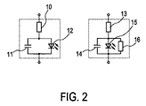
上記の放電挙動は、図2に概略的に例として示される、短絡がある場合とない場合のOLEDの等価回路を考慮することによって理解されることができる。短絡のない状況(図の左側)では、抵抗10は、特に大面積OLEDで発生する場合がある横方向の損失をモデル化し、容量11は、OLEDの内部容量を表し、ダイオード12は、OLEDの発光領域の非線形挙動をモデル化する。同じ要素、抵抗13、容量14及びダイオード15が、短絡がある状況(図の右側)において存在するが、短絡に起因して、更なる抵抗16が、OLEDの内部容量15に並列に現れる。短絡の存在下での内部容量15の急速放電の原因となるのはこの更なる抵抗16である。
The above discharge behavior can be understood by considering the equivalent circuit of an OLED with and without a short circuit, schematically illustrated in FIG. In the absence of a short circuit (left side of the figure),
図3は、ここでは300mAの駆動電流(図の上のグラフ中の曲線L3)が、ここでは0.2msの短い期間の間オフに切り替えられたときの、短絡がある場合とない場合の、図1のOLEDの放電挙動の詳細を概略的に例として示す。図の下のグラフ中の曲線L4から分かるように、短絡のない状況では、OLEDを通した電圧は、駆動電流がオフに切り替えられる0.2msの期間の間に9Vから約8.5Vへ低下する。対照的に、短絡がある状況(図の下のグラフ中の曲線L5)では、OLEDを通した電圧は、300mAの駆動電流がOLEDに供給されるときに2.3Vであり、駆動電流がオフに切り替えられる0.2msの期間の間にほぼ即座に(ほぼ)0Vに落ちる。すでに上記で言及されたように、非常に異なる時定数が影響する、欠陥のないOLEDと欠陥のあるOLED(「発光素子」)の放電挙動におけるこの差異は、OLED中の短絡を検出するために用いられることができる。 Figure 3 shows a diagram with and without a short circuit, where the 300 mA drive current (curve L3 in the upper graph) is switched off here for a short period of 0.2 ms. The details of the discharge behavior of 1 OLED are shown schematically as an example. As can be seen from the curve L4 in the lower graph, in the absence of a short circuit, the voltage through the OLED drops from 9V to about 8.5V during the 0.2ms period when the drive current is switched off. In contrast, in a situation where there is a short (curve L5 in the graph below the diagram), the voltage through the OLED is 2.3V when 300mA of drive current is supplied to the OLED, and the drive current is turned off. It falls to 0V almost immediately during the 0.2ms period to be switched. As already mentioned above, this difference in the discharge behavior of defect-free and defective OLEDs (“light emitting elements”), influenced by very different time constants, is necessary to detect short circuits in OLEDs. Can be used.
図4は、エレクトロルミネセンス装置20の第1の実施の形態を概略的に例として示す。エレクトロルミネセンス装置20は、ここでは内部容量(図示せず)からなる容量を持つ発光素子21(ここではOLED)、OLED 21に駆動電流に供給するためにOLED 21に接続されている切替可能な電流源22、及び、OLED 21中の短絡を検出するための短絡検出回路23を有する。
FIG. 4 schematically shows a first embodiment of the
短絡検出回路23は、トリガーされるとOLED 21を通した電圧測定するための、ここではサンプルホールド素子である、トリガー可能な電圧測定ユニット24、駆動電流がOLED 21に供給されない期間Δtの後、OLED 21を通した電圧を測定するためにサンプルホールド素子24をトリガーするためのトリガリング・ユニット25、及び、OLED 21を通した測定された電圧に基づいてOLED 21中の短絡を検出するための短絡検出ユニット26を有する。この例では、トリガリング・ユニット25は、切替可能な電流源22に接続されて、期間Δtの間、切替可能な電流源22をオフに切り替えるように適応される。さらに、短絡検出回路23は、この実施の形態において、OLED 21中に短絡が検出された場合に、エレクトロルミネセンス装置20をオフにするための短絡保護ユニット27を更に有する。短絡保護ユニット27は、この場合には、切替可能な電流源22に接続されて、OLED 21中に短絡が検出された場合に、切替可能な電流源22をオフにするように適応される。
The short-circuit detection circuit 23 is a sample-and-hold element, here a triggerable
短絡検出回路23による短絡検出は、図4の短絡検出回路23の時間的挙動の詳細を概略的に例として示す図5を参照して以下で説明される。図の一番下のグラフ中の曲線L6から分かるように、大部分の時間の間、切替可能な電流源22は、OLED 21に、ここでは300mAの駆動電流を供給する。しかしながら、周期的に、切替可能な電流源22は、それぞれの期間Δtの間、トリガリング・ユニット25によってオフに切り替えられる。期間Δtの長さは、この例では、10μsである。図の上から2番目のグラフの曲線L7からさらに分かるように、切替可能な電流源22の周期的なスイッチング・オフと同期して、トリガリング・ユニット25は、ここでは、周期的に1Vから0Vに設定される電圧信号(曲線L7)をサンプルホールド素子24に供給することによって、それぞれの10μsの期間Δtの後でOLED 21を通した電圧を測定するために、周期的にサンプルホールド素子24をトリガーする。そして、OLED 21を横切るこの電圧の時間的挙動は、図の下から2番目のグラフ中の曲線L8によって与えられる。すでに上記で説明されたように、OLED 21が300mAの駆動電流を供給される場合、短絡なしではOLED 21は9Vの電圧で動作し、OLED電圧は、駆動電流がオフに切り替えられる各々の10μsの期間Δtの間、9Vから約8.5Vまで降下する(曲線L8の左部分)。約6.5msにおいて、前のトリガー「イベント」の直後に、短絡がOLED 21中に発生する。この短絡に起因して、OLED 21を通した電圧は、駆動電流がOLED 21に供給されているときに、約2.3Vまで降下し、駆動電流がオフに切り替えられる10μsの期間Δtの間に(ほぼ)0Vへとほとんど即座に降下する(曲線L8の右部分)。ここで、OLED 21を通した測定された電圧は、すなわち、それぞれの10μsの期間Δtの後にサンプルホールド素子24によって測定された電圧は、図の一番上のグラフ中の曲線L9によって与えられる。以上のように、この電圧は、約6.5msにおける短絡の発生前には8.5Vである。というのも、この電圧が、短絡のない状況において、OLED 21を通した電圧がそれぞれの10μsの期間Δtの間に降下する値であるからである。対照的に、約6.5msにおける短絡の発生後の最初の10μsの期間Δtから、OLED 21を通した測定された電圧は、(ほぼ)0Vである。というのも、この電圧が、短絡がある状況において、OLED 21を通した電圧がそれぞれの10μsの期間Δtの間に降下する値であるからである。OLED 21を横切るそれぞれの測定される電圧は、OLED 21を通した電圧が次の10μsの期間Δtの後に新たに測定されるまで、この例では、サンプルホールド素子24によって保持される。
Short circuit detection by the short circuit detection circuit 23 will be described below with reference to FIG. 5, which schematically shows details of the temporal behavior of the short circuit detection circuit 23 of FIG. 4 as an example. As can be seen from the curve L6 in the bottom graph of the figure, the switchable
再度図4を参照して、この例では、短絡検出ユニット26は、OLED 21を通した測定された電圧が(ほぼ)0Vである場合に、OLED 21中に短絡を検出するように適応される。
Referring again to FIG. 4, in this example, the
図6は、エレクトロルミネセンス装置30の第2の実施の形態を概略的に例として示す。エレクトロルミネセンス装置30は、ここでは(図に示されない)内部容量からなる容量持つここではOLEDである発光素子31、OLED 31に駆動電流を供給するためのOLED 31に接続されている切替可能な電流源32、及び、OLED 31中の短絡を検出するための短絡検出回路33を含む。
FIG. 6 schematically shows a second embodiment of the
短絡検出回路33は、トリガーされるとOLED 31を通した電圧を測定するための、ここではサンプルホールド素子であるトリガー可能な電圧測定ユニット34、駆動電流がOLED 31に供給されない期間Δtの後にOLED 31を通した電圧を測定するためにサンプルホールド素子34をトリガーするためのトリガリング・ユニット35、及び、OLED 31を通した測定された電圧に基づいてOLED 31中の短絡を検出するための短絡検出ユニット36を含む。この例では、トリガリング・ユニット35は、切替可能な電流源32に接続されて、期間Δtの間、切替可能な電流源32をオフ切り替えるように適応されている。さらに、短絡検出回路33は、この実施の形態において、短絡がOLED 31中に検出される場合に、エレクトロルミネセンス装置30をオフにするための短絡保護ユニット37を更に備える。短絡保護ユニット37は、この場合には、切替可能な電流源32に接続されて、短絡がOLED 31中に検出される場合、切替可能な電流源32をオフにするように適応されている。
The short
ここで、エレクトロルミネセンス装置30は、ここでは(図に示されない)内部容量からなる容量を持つ、ここでは更なるOLEDである更なる発光素子38を更に備え、更なるOLED 38は、OLED 31と直列に接続され、切替可能な電流源32は、OLED 31及び更なるOLED 38の直列接続に駆動電流を供給するように適応されている。短絡検出回路33は、トリガーされると、更なるOLED 38を通した電圧を測定するための、ここでは更なるサンプルホールド素子である更なるトリガー可能な電圧測定ユニット39を更に備え、トリガリング・ユニット35は、駆動電流が更なるOLED 38に供給されない期間Δtの後に更なるOLED 38を通した電圧を測定するために更なるサンプルホールド素子39をトリガーするように適応され、短絡検出ユニット36は、更なるOLED 38を通した測定された電圧に基づいて更なるOLED 38中の短絡を検出するように適応される。
Here, the
ここで、エレクトロルミネセンス装置30は、ここでは(図に示されない)内部容量からなる容量を持つ、ここでは更なるOLEDである更なる発光素子40を更に備え、更なるOLED 40は、OLED 31に並列に接続され、切替可能な電流源32は、OLED 31及び更なるOLED 40の並列接続に駆動電流を供給するように適応される。短絡検出回路33は、トリガーされると、更なるOLED 40を通した電圧を測定するための、ここでは更なるサンプルホールド素子である更なるトリガー可能な電圧測定ユニット41を更に備え、トリガリング・ユニット35は、駆動電流が更なるOLED 40に供給されない期間Δtの後に更なるOLED 40を通した電圧を測定するために更なるサンプルホールド素子41をトリガーするように適応され、短絡検出ユニット36は、更なるOLED 40を通した測定された電圧に基づいて更なるOLED 40中の短絡を検出するように適応される。
Here, the
図6から分かるように、この実施の形態において、エレクトロルミネセンス装置30は、切替可能な電流源32と発光素子31との間に直列に接続される、ここではダイオードであるデカップリング素子44と、切替可能な電流源32と更なる発光素子40との間に直列に接続される、ここでは更なるダイオードである更なるデカップリング素子45とを更に備える。そのうえ、エレクトロルミネセンス装置30はさらに、他のOLED 31, 38, 40とともに2x2アレイで配置される更なるOLED 42を更に備え、短絡検出回路33は、さらに更なるサンプルホールド素子43を含む。この構成によって、2x2アレイ配置中で、短絡を有するOLED 31, 38, 40, 42を一意的に特定することが可能である。
As can be seen from FIG. 6, in this embodiment, the
短絡検出回路33による短絡検出は、図6の短絡検出回路33の時間的挙動の詳細を概略的に例として示す図7を参照して以下に説明される。図の一番下のグラフ中の曲線L10及びL11から分かるように、大部分の時間の間、切替可能な電流源32は、短絡なしで、OLED 31, 38及び40, 42の2つのストリングに実質的に均等に分配される合計600mAの駆動電流を、OLED 31, 38, 40, 42に供給する。しかしながら、周期的に、切替可能な電流源32は、それぞれの期間Δtの間、トリガリング・ユニット35によってオフに切り替えられる。期間Δtの長さは、この例では、10μsである。図の上から5番目のグラフ中の曲線L12からさらに分かるように、切替可能な電流源32の周期的なスイッチング・オフと同期して、トリガリング・ユニット35は、それぞれの10μsの期間Δtの後にOLED 31, 38, 40, 42を通した電圧を測定するために、ここでは、サンプルホールド素子34, 39, 41, 43に、周期的に1Vから0Vに設定される電圧信号(曲線L12)を供給することによって、サンプルホールド素子34, 39, 41, 43を周期的にトリガーする。そして、OLED31, 38, 40, 42を通したこれらの電圧の時間的挙動は、図の下から2番目から5番目のグラフ中の曲線L13, L14, L15, L16によって与えられる。すでに上記で説明されたように、OLED 31, 38, 40, 42に300mAの駆動電流が供給される場合、OLED 31, 38, 40, 42は、短絡なしでは、9Vの電圧で動作する(曲線L13, L14, L15, L16の左端部分)。約0.2msにおいて、2つのトリガー「イベント」間に、OLED 31中に短絡が発生する。短絡に起因して、OLED 31を通した電圧は、駆動電流がOLED 31に供給されているとき、約5Vまで降下し、駆動電流がオフに切り替えられている10μsの期間Δtの間に(ほぼ)0Vへ実質的に即座に降下する(曲線L13の左部分)。OLED 31中の短絡は、他のOLED 38, 40, 42を通した電圧と同様に、OLED 31, 38及び40, 42の2つのストリングへの駆動電流の分布に影響を与える(曲線L10, L11及びL14, L15, L16)。そして、約1.2ms, 2.2ms及び3.2msにおいて、他のOLED 38, 40, 42中に更なる短絡が発生する。これらの短絡に起因して、OLED 38, 40, 42を通した電圧は、駆動電流がOLED 38, 40, 42に供給されているとき、(すでに欠陥を生じたOLEDのそれぞれの数に依存する)それぞれの電圧に降下し、OLED 38, 40, 42それぞれにおいて、駆動電流がオフに切り替えられている10μsの期間Δtの間に(ほぼ)0Vまでほとんど即座に降下する(曲線L14, L15, L16)。ここで、OLED 31, 38, 40, 42を通した測定される電圧、すなわち、それぞれの10μsの期間Δtの後にサンプルホールド素子34, 39, 41, 43によって測定される電圧は、図の上4つのグラフ中の曲線L17, L18, L19, L20によって与えられる。以上のように、これらの電圧は、約0.2ms, 1.2ms, 2.2ms及び3.2msにおける短絡の発生の前には、約8.5Vか僅かに低い。というのも、これらは、短絡がない状況において、OLED31, 38, 40, 42を通した電圧がそれぞれの10μsの期間Δtの間に降下する値であるからである。対照的に、約0.2ms, 1.2ms, 2.2ms, 3.2msにおける短絡の発生後の最初の10μsの期間Δtから、OLED31, 38, 40, 42を通した測定される電圧は、(ほぼ)0Vである。というのも、これらは、短絡がある状況において、OLED31, 38, 40, 42を通した電圧がそれぞれの10μsの期間Δtの間に降下する値であるからである。OLED31, 38, 40, 42を横切るそれぞれの測定される電圧は、OLED31, 38, 40, 42を通した電圧が次の10μsの期間Δtの後に新たに測定されるまで、この例では、サンプルホールド素子34, 39, 41, 43によって保持される。
Short circuit detection by the short
再度図7を参照して、この例では、短絡検出ユニット36は、OLED 31を通した測定された電圧が(ほぼ)0Vである場合に、OLED 31中に短絡を検出するように適応される。同様に、短絡検出ユニット36は、任意の他のOLED38, 40, 42を通した測定された電圧が(ほぼ)0Vである場合に、任意の他のOLED38, 40, 42中に短絡を検出するように適応される。
Referring again to FIG. 7, in this example, the
図8は、エレクトロルミネセンス装置50の第3の実施の形態を概略的に例として示す。エレクトロルミネセンス装置50は、ここでは(図に示されない)内部容量からなる容量をもつ、ここではOLEDである発光素子51、OLED 51に駆動電流を供給するためのOLED 51に接続されている切替可能な電流源52、及び、OLED 51中の短絡を検出するための短絡検出回路53を含む。
FIG. 8 schematically shows a third embodiment of the electroluminescent device 50 as an example. The electroluminescent device 50 here has a capacity consisting of an internal capacity (not shown in the figure), here a
短絡検出回路53は、トリガーされるとOLED 51を通した電圧を測定するための、ここではサンプルホールド素子であるトリガー可能な電圧測定ユニット54、駆動電流がOLED 51に供給されない期間Δtの後にOLED 51を通した電圧を測定するためにサンプルホールド素子54をトリガーするためのトリガリング・ユニット55、及び、OLED 51を通した測定された電圧に基づいてOLED 51中の短絡を検出するための短絡検出ユニット56を含む。この例では、トリガリング・ユニット55は、切替可能な電流源52に接続されて、期間Δtの間、切替可能な電流源52をオフ切り替えるように適応されている。さらに、短絡検出回路53は、この実施の形態において、短絡がOLED 51中に検出される場合に、エレクトロルミネセンス装置50をオフにするための短絡保護ユニット57を更に備える。短絡保護ユニット57は、この場合には、切替可能な電流源52に接続されて、短絡がOLED 51中に検出される場合、切替可能な電流源52をオフにするように適応されている。
The short
ここで、エレクトロルミネセンス装置50は、ここでは(図に示されない)内部容量からなる容量を持つ、ここでは更なるOLEDである更なる発光素子58を更に備え、更なるOLED 58は、OLED 51と直列に接続され、切替可能な電流源52は、OLED 51及び更なるOLED 58の直列接続に駆動電流を供給するように適応されている。短絡検出回路53は、トリガーされると更なるOLED 58を通した電圧を測定するための、ここでは更なるサンプルホールド素子である更なるトリガー可能な電圧測定ユニット59を更に備え、トリガリング・ユニット55は、期間Δtの後に更なるOLED 58を通した電圧を測定するために更なるサンプルホールド素子59をトリガーするように適応され、短絡検出ユニット56は、更なるOLED 58を通した測定された電圧に基づいて更なるOLED 58中の短絡を検出するように適応される。
Here, the electroluminescent device 50 further comprises a further light-emitting
ここで、エレクトロルミネセンス装置50は、ここでは(図に示されない)内部容量からなる容量を持つ、ここでは更なるOLEDである更なる発光素子60を更に備え、更なるOLED 60はOLED 51に並列に接続され、更なる発光素子60に駆動電流を供給するために、更なる切替可能な電流源64が更なる発光素子60に接続される。(切替可能な電流源52及び更なる切替可能な電流源64は両方とも、この実施の形態において、電源65によって電力を供給される)。短絡検出回路53は、トリガーされると、更なるOLED 60を通した電圧を測定するための、ここでは更なるサンプルホールド素子である更なるトリガー可能な電圧測定ユニット61を更に備え、トリガリング・ユニット55は、駆動電流が更なる発光素子60に供給されない期間Δtの後に更なるOLED 60を通した電圧を測定するために更なるサンプルホールド素子61をトリガーするように適応され、短絡検出ユニット56は、更なるOLED 60を通した測定された電圧に基づいて更なるOLED 60中の短絡を検出するように適応される。
Here, the electroluminescent device 50 further comprises a further light-emitting
図8から分かるように、この実施の形態において、エレクトロルミネセンス装置50は、図6(参照符号44及び45を参照)を参照して説明される第2の実施の形態において利用されるようなデカップリング素子を有しない。その代わりに、相当するデカップリングは、2つの別々の切替可能な電流源52及び64によって達成される。エレクトロルミネセンス装置50は、他のOLED 51, 58, 60とともに2x2のアレイで配置される更なるOLED 62を更に備え、短絡検出回路53は、更なるサンプルホールド素子63を有する。この構成では、2x2アレイ配置中のOLED51, 58, 60, 62を一意的に特定することが可能である。
As can be seen from FIG. 8, in this embodiment, the electroluminescent device 50 is as utilized in the second embodiment described with reference to FIG. 6 (see
以下において、発光素子21中の短絡を検出するための短絡検出方法の実施の形態100が、図9に示されるフローチャートを参照して例として説明される。短絡検出方法100は、図4に示されるような、ここでは(図に示されない)内部容量からなる容量をもつ、ここではOLEDである発光素子21 、OLED 21に駆動電流を供給するためのOLED 21に接続されている切替可能な電流源22、及び、OLED 21中の短絡を検出するための短絡検出回路23を有するエレクトロルミネセンス装置20で使用するために適応されている。
In the following, an
ステップ101において、トリガー可能な電圧測定ユニット21は、トリガリング・ユニット25によって、駆動電流が発光素子21に供給されない期間Δtの後に発光素子21を通した電圧を測定するためにトリガーされる。ステップ102において、トリガーされると、トリガー可能な電圧測定ユニット24によって、発光素子21を通した電圧が測定される。ステップ103において、短絡検出ユニット26によって、発光素子21を通した測定された電圧に基づいて、発光素子21中の短絡が検出される。
In
図9に示される短絡検出方法100の実施の形態において、短絡検出方法100は、例えば図4に示されるようなエレクトロルミネセンス装置20で使用するために適応されているが、当該方法は、図6に示されるようなエレクトロルミネセンス装置30、または、図8に示されるようなエレクトロルミネセンス装置50で使用するために適応されることができる。短絡検出方法の更なる特徴は、図4に示されるエレクトロルミネセンス装置20、図6に示されるエレクトロルミネセンス装置30及び図8に示されるエレクトロルミネセンス装置50に関する記述から理解されることができる。
In the embodiment of the
図4、6および8に示されるエレクトロルミネセンス装置20, 30, 50の実施の形態において、発光素子は、(図示されない)内部容量からなる容量を持つOLEDであるが、他の実施の形態では、発光素子は、LEDに並列に接続された外部容量からなる容量を持つLEDであることもできる。
In the embodiments of the
なお、図5および7において、切替可能な電流源が、(ほぼ)完全に一定の駆動電流を供給することが可能である線形ドロップアウト・レギュレータを用いて実現される場合についての波形が示される。しかしながら、切替可能な電流源は、例えば非常に効率的なヒステリシス制御降圧型スイッチモード電源を用いて実現されることも可能である。そのような電源の典型的な特性は、供給される電流が、例えば1〜2MHzの範囲である場合がある非常に高いスイッチング周波数で上側値と下側値(すなわち、ヒステリシス値)との間で変化することである。ヒステリシス幅を可能な限り小さくすることがそのような電源のための設計目標であるが、それは完全に回避されることはできない。したがって、そのような電源については、期間Δtは、スイッチング周波数に対応する期間より長いことが好ましい。 5 and 7 show waveforms for a case where the switchable current source is implemented using a linear dropout regulator that can supply a (substantially) completely constant drive current. . However, the switchable current source can also be realized using, for example, a very efficient hysteresis controlled step-down switch mode power supply. The typical characteristic of such a power supply is that the supplied current is between an upper value and a lower value (i.e. a hysteresis value) at a very high switching frequency, which may be in the range of e.g. 1-2 MHz. To change. Although making the hysteresis width as small as possible is a design goal for such a power supply, it cannot be completely avoided. Therefore, for such a power supply, the period Δt is preferably longer than the period corresponding to the switching frequency.
図5および7は、トリガリング・ユニットが周期的にトリガー可能な電圧測定ユニットをトリガーし、OLED中の短絡の存在についてOLEDが繰り返し確認される実施例を示すが、追加的に或いは代わりに、トリガリング・ユニットは、エレクトロルミネセンス装置をオンまたはオフにするプロセスの間にトリガー可能な電圧測定ユニットをトリガーするように適応されていることも可能である。切替可能な電流源がパルス幅変調信号によってオンに切り替えられているパルス幅変調時間間隔の範囲に期間(Δt)が入るように、トリガリング・ユニットは、切替可能な電流源のオンとオフを切り替えるためにパルス幅変調信号と同期されるように適応されることも可能である。 FIGS. 5 and 7 show examples where the triggering unit triggers a periodically triggerable voltage measurement unit and the OLED is repeatedly checked for the presence of a short in the OLED, but in addition or alternatively, The triggering unit can also be adapted to trigger a voltage measurement unit that can be triggered during the process of turning the electroluminescent device on or off. The triggering unit turns on and off the switchable current source so that the period (Δt) falls within the range of the pulse width modulation time interval in which the switchable current source is switched on by the pulse width modulation signal. It can also be adapted to be synchronized with the pulse width modulated signal for switching.
図面、開示及び添付の請求の範囲の検討から、開示された実施の形態に対する他のバリエーションは、請求された発明を実施する際に、当業者によって理解され、遂行されることができる。 From a review of the drawings, the disclosure and the appended claims, other variations to the disclosed embodiments can be understood and carried out by those skilled in the art in practicing the claimed invention.
請求の範囲において、「有する」「含む」等の用語は、他の要素又はステップを除外せず、単数表現は複数を除外しない。 In the claims, terms such as “comprising” do not exclude other elements or steps, and the singular expression does not exclude a plurality.
一つのユニットまたは装置が、請求項中に列挙されるいくつかのアイテムの機能を実現することができる。例えば、トリガリング・ユニット25、短絡検出ユニット26及び短絡保護ユニット27が3つの別々のユニットとして図示されている図4に示されるエレクトロルミネセンス装置20の第1の実施の形態において、それらは、一つのユニットとしても実現されることができる。単に特定の手段が相互に異なる従属請求項中に列挙されているからといって、これらの手段の組み合わせが有効に用いられることができないことを意味しない。
A single unit or device may fulfill the functions of several items recited in the claims. For example, in the first embodiment of the
コンピュータプログラムは、他のハードウェアと共に又はその一部として供給される、適切な媒体(例えば光学記憶媒体若しくは固体素子媒体)上で格納/配布されることができるが、インターネット又は他の有線若しくは無線通信システムを介するような他の形態で配信されることもできる。 The computer program can be stored / distributed on suitable media (e.g., optical storage media or solid state media) supplied with or as part of other hardware, but can also be internet or other wired or wireless It can also be distributed in other forms, such as via a communication system.
請求の範囲におけるいかなる参照符号も、その範囲を制限するものとして解釈されるべきでない。 Any reference signs in the claims should not be construed as limiting the scope.
本発明は、容量を持つ発光素子、発光素子に駆動電流を供給するための発光素子に接続されている切替可能な電流源、及び、発光素子中の短絡を検出するための短絡検出回路を有するエレクトロルミネセンス装置に関する。短絡検出回路は、トリガーされると、発光素子を通した電圧を測定するためのトリガー可能な電圧測定ユニット、駆動電流が発光素子に供給されない期間の後に発光素子を通した電圧を測定するためにトリガー可能な電圧測定ユニットをトリガーするためのトリガリング・ユニット、及び、発光素子を通した測定された電圧に基づいて発光素子中の短絡を検出するための短絡検出ユニットを有する。それによって、短絡検出は、製造許容範囲などに対して影響を受けにくい。 The present invention includes a light emitting element having a capacity, a switchable current source connected to the light emitting element for supplying a driving current to the light emitting element, and a short circuit detection circuit for detecting a short circuit in the light emitting element. The present invention relates to an electroluminescence device. Short circuit detection circuit, when triggered, a triggerable voltage measurement unit for measuring the voltage through the light emitting element, to measure the voltage through the light emitting element after a period when no drive current is supplied to the light emitting element A triggering unit for triggering a triggerable voltage measurement unit and a short detection unit for detecting a short circuit in the light emitting element based on the measured voltage through the light emitting element. As a result, short circuit detection is less susceptible to manufacturing tolerances and the like.
Claims (14)
前記発光素子に駆動電流を供給するために前記発光素子に接続される切替可能な電流源、及び
前記発光素子中の短絡を検出するための短絡検出回路、
を有し、
前記短絡検出回路は、
トリガーされると、前記発光素子を通した電圧を測定するためのトリガー可能な電圧測定ユニット、
前記駆動電流が前記発光素子に供給されない期間の後に前記発光素子を通した電圧を測定するために前記トリガー可能な電圧測定ユニットをトリガーするためのトリガリング・ユニット、及び
前記発光素子中の測定された電圧に基づいて前記発光素子中の短絡を検出するための短絡検出ユニット、
を有する、エレクトロルミネッセンス装置。 A light emitting device with a capacity;
A switchable current source connected to the light emitting element to supply a drive current to the light emitting element, and a short circuit detection circuit for detecting a short circuit in the light emitting element;
Have
The short circuit detection circuit is:
When triggered, a triggerable voltage measurement unit for measuring the voltage through the light emitting element,
A triggering unit for triggering the triggerable voltage measurement unit to measure the voltage across the light emitting element after a period in which the drive current is not supplied to the light emitting element, and the measured in the light emitting element A short detection unit for detecting a short circuit in the light emitting element based on the voltage
An electroluminescence device.
トリガリング・ユニットにより、前記駆動電流が前記発光素子に供給されない期間の後に前記発光素子を通した電圧を測定するためにトリガー可能な電圧測定ユニットをトリガーし、
トリガーされると、前記トリガー可能な電圧測定ユニットにより、前記発光素子を通した電圧を測定し、
短絡検出ユニットにより、前記発光素子を通した測定された電圧に基づいて前記発光素子中の短絡を検出する、方法。 A short-circuit detection method for detecting a short circuit in a light-emitting element having a capacity, the short-circuit detection method being switchable connected to the light-emitting element to supply a driving current to the light-emitting element and the light-emitting element Used in an electroluminescent device having a current source,
Triggering a voltage measurement unit that can be triggered to measure a voltage across the light emitting element after a period when the drive current is not supplied to the light emitting element by a triggering unit;
When triggered, the triggerable voltage measurement unit measures the voltage through the light emitting element,
A method of detecting a short circuit in the light emitting element based on a measured voltage through the light emitting element by a short circuit detection unit.
Applications Claiming Priority (3)
| Application Number | Priority Date | Filing Date | Title |
|---|---|---|---|
| EP14152787.9 | 2014-01-28 | ||
| EP14152787 | 2014-01-28 | ||
| PCT/EP2015/050437 WO2015113805A1 (en) | 2014-01-28 | 2015-01-13 | Electroluminescent device with short detection circuit |
Publications (3)
| Publication Number | Publication Date |
|---|---|
| JP2017509105A true JP2017509105A (en) | 2017-03-30 |
| JP2017509105A5 JP2017509105A5 (en) | 2017-06-29 |
| JP6220981B2 JP6220981B2 (en) | 2017-10-25 |
Family
ID=50064409
Family Applications (1)
| Application Number | Title | Priority Date | Filing Date |
|---|---|---|---|
| JP2016545784A Active JP6220981B2 (en) | 2014-01-28 | 2015-01-13 | Electroluminescence device with short circuit detection circuit |
Country Status (7)
| Country | Link |
|---|---|
| US (1) | US9713224B2 (en) |
| EP (1) | EP3100062B1 (en) |
| JP (1) | JP6220981B2 (en) |
| CN (1) | CN105981475B (en) |
| BR (1) | BR112016017176B1 (en) |
| RU (1) | RU2668946C2 (en) |
| WO (1) | WO2015113805A1 (en) |
Families Citing this family (2)
| Publication number | Priority date | Publication date | Assignee | Title |
|---|---|---|---|---|
| CN106448564B (en) | 2016-12-20 | 2019-06-25 | 京东方科技集团股份有限公司 | OLED pixel circuit and driving method thereof, and display device |
| DE102021100854A1 (en) | 2021-01-18 | 2022-07-21 | HELLA GmbH & Co. KGaA | Control and/or regulating means, circuit arrangement and method for driving light-emitting diodes in a light-emitting diode array |
Citations (7)
| Publication number | Priority date | Publication date | Assignee | Title |
|---|---|---|---|---|
| JP2005003606A (en) * | 2003-06-13 | 2005-01-06 | Mecc Co Ltd | Inspection device of display panel |
| US20060170287A1 (en) * | 2005-01-31 | 2006-08-03 | Koito Manufacturing Co., Ltd. | Lighting control circuit for vehicle lighting fixture |
| US20070205793A1 (en) * | 2006-03-02 | 2007-09-06 | Hung-Tsung Wang | Method and apparatus for silent current detection |
| US20080231198A1 (en) * | 2007-03-23 | 2008-09-25 | Zarr Richard F | Circuit for driving and monitoring an LED |
| JP2009238435A (en) * | 2008-03-26 | 2009-10-15 | Panasonic Electric Works Co Ltd | Light emitting device |
| US20100085074A1 (en) * | 2008-10-08 | 2010-04-08 | Aung Aung Yinn | Power converter, short detection circuit thereof, and method for detecting short |
| JP2013012487A (en) * | 2009-10-02 | 2013-01-17 | Lecip Holdings Corp | Light-emitting diode illumination circuit and luminaire |
Family Cites Families (17)
| Publication number | Priority date | Publication date | Assignee | Title |
|---|---|---|---|---|
| JPH07140490A (en) | 1993-11-16 | 1995-06-02 | Hitachi Electron Eng Co Ltd | Short circuit inspection method for TFT substrate |
| RU2130617C1 (en) * | 1995-02-14 | 1999-05-20 | Акционерное общество открытого типа "Автоэлектроарматура" | Gear testing light-emitting diodes |
| DE19734750C2 (en) | 1997-08-12 | 2003-04-30 | Reitter & Schefenacker Gmbh | Rear lights of motor vehicles |
| JP4033166B2 (en) * | 2004-04-22 | 2008-01-16 | セイコーエプソン株式会社 | Electronic circuit, driving method thereof, electro-optical device, and electronic apparatus |
| US7800876B2 (en) * | 2006-01-09 | 2010-09-21 | Microsemi Corp. - Analog Mixed Signal Group Ltd. | Fault detection mechanism for LED backlighting |
| AT504949B1 (en) * | 2007-02-20 | 2008-11-15 | Zizala Lichtsysteme Gmbh | CIRCUIT ARRANGEMENT FOR DETECTING A SHORT-CIRCUIT OF LUMINOUS DIODES |
| JP2008251276A (en) | 2007-03-29 | 2008-10-16 | Stanley Electric Co Ltd | Fault detection device for light emitting diode circuit |
| JP2009038247A (en) | 2007-08-02 | 2009-02-19 | Mitsubishi Electric Corp | LED lighting device |
| JP2010129612A (en) | 2008-11-25 | 2010-06-10 | Panasonic Electric Works Co Ltd | Lighting device |
| JP5901966B2 (en) * | 2011-01-13 | 2016-04-13 | ローム株式会社 | LED short detection circuit, LED driving device, LED lighting device, vehicle |
| JP2013037763A (en) | 2011-06-29 | 2013-02-21 | Arco Giken:Kk | Led lighting circuit and led lighting device |
| US9192014B2 (en) | 2011-07-19 | 2015-11-17 | Nxp B.V. | LED short circuit protection |
| KR101876561B1 (en) * | 2011-08-26 | 2018-07-10 | 엘지디스플레이 주식회사 | Liquid Crystal Display Device and Driving Method the same |
| US8773038B2 (en) * | 2011-08-26 | 2014-07-08 | Infineon Technologies Ag | Driver circuit for efficiently driving a large number of LEDs |
| JP5288082B1 (en) | 2011-11-28 | 2013-09-11 | コニカミノルタ株式会社 | Light emitting module |
| US8933647B2 (en) * | 2012-07-27 | 2015-01-13 | Infineon Technologies Ag | LED controller with current-ripple control |
| TWI513363B (en) * | 2012-12-07 | 2015-12-11 | Upi Semiconductor Corp | Short-circuit protection circuit of light emitting diode and short-circuit protection method thereof and light emitting diode driving apparatus using the same |
-
2015
- 2015-01-13 RU RU2016134837A patent/RU2668946C2/en active
- 2015-01-13 JP JP2016545784A patent/JP6220981B2/en active Active
- 2015-01-13 WO PCT/EP2015/050437 patent/WO2015113805A1/en not_active Ceased
- 2015-01-13 BR BR112016017176-4A patent/BR112016017176B1/en active IP Right Grant
- 2015-01-13 EP EP15700368.2A patent/EP3100062B1/en active Active
- 2015-01-13 CN CN201580006291.8A patent/CN105981475B/en active Active
- 2015-01-13 US US15/114,877 patent/US9713224B2/en active Active
Patent Citations (7)
| Publication number | Priority date | Publication date | Assignee | Title |
|---|---|---|---|---|
| JP2005003606A (en) * | 2003-06-13 | 2005-01-06 | Mecc Co Ltd | Inspection device of display panel |
| US20060170287A1 (en) * | 2005-01-31 | 2006-08-03 | Koito Manufacturing Co., Ltd. | Lighting control circuit for vehicle lighting fixture |
| US20070205793A1 (en) * | 2006-03-02 | 2007-09-06 | Hung-Tsung Wang | Method and apparatus for silent current detection |
| US20080231198A1 (en) * | 2007-03-23 | 2008-09-25 | Zarr Richard F | Circuit for driving and monitoring an LED |
| JP2009238435A (en) * | 2008-03-26 | 2009-10-15 | Panasonic Electric Works Co Ltd | Light emitting device |
| US20100085074A1 (en) * | 2008-10-08 | 2010-04-08 | Aung Aung Yinn | Power converter, short detection circuit thereof, and method for detecting short |
| JP2013012487A (en) * | 2009-10-02 | 2013-01-17 | Lecip Holdings Corp | Light-emitting diode illumination circuit and luminaire |
Also Published As
| Publication number | Publication date |
|---|---|
| EP3100062B1 (en) | 2017-09-13 |
| RU2016134837A3 (en) | 2018-08-02 |
| CN105981475A (en) | 2016-09-28 |
| RU2016134837A (en) | 2018-03-07 |
| JP6220981B2 (en) | 2017-10-25 |
| BR112016017176A2 (en) | 2017-08-08 |
| WO2015113805A1 (en) | 2015-08-06 |
| EP3100062A1 (en) | 2016-12-07 |
| CN105981475B (en) | 2018-08-28 |
| US20160353546A1 (en) | 2016-12-01 |
| US9713224B2 (en) | 2017-07-18 |
| RU2668946C2 (en) | 2018-10-05 |
| BR112016017176B1 (en) | 2022-05-24 |
Similar Documents
| Publication | Publication Date | Title |
|---|---|---|
| JP5904551B2 (en) | Driver for analyzing the state of the organic light emitting diode element and for supplying a recovery voltage to the organic light emitting diode element | |
| US9999110B2 (en) | LED driver with comprehensive fault protections | |
| US8957599B2 (en) | Supervision circuit for organic light emitting diode | |
| JP5900980B2 (en) | Light emitting device failure detector and light emitting device failure detection method | |
| US20170215248A1 (en) | Method for operating an optoelectronic assembly and optoelectronic assembly | |
| US8138679B2 (en) | Organic electroluminescent light emitting device for restoring normal operation after low-voltage errors | |
| US20120194076A1 (en) | Lighting control device | |
| KR20160128932A (en) | Device and method for detecting a short-circuited light-emitting diode in a light device of a motor vehicle | |
| CN104704916A (en) | Method and apparatus for the diagnosis of faulty light-emitting means | |
| US9658274B2 (en) | Light-emitting element failure detector and method for detecting light-emitting element failure | |
| CN102548131B (en) | Power supply device and method for lighting system with light-emitting diodes and lighting assembly comprising one such device | |
| JP6220981B2 (en) | Electroluminescence device with short circuit detection circuit | |
| US20180160506A1 (en) | Driving module and light source system having the driving module | |
| US10231311B2 (en) | Method for operating an optoelectronic assembly and optoelectronic assembly | |
| US20130140991A1 (en) | Direction indication lamp control device, direction indication device and wire disconnection detection method of the direction indication device | |
| JP2014086363A (en) | Led drive device, led drive method, and luminaire | |
| JP2017509105A5 (en) | ||
| JP2020077458A (en) | Oled driving device |
Legal Events
| Date | Code | Title | Description |
|---|---|---|---|
| RD04 | Notification of resignation of power of attorney |
Free format text: JAPANESE INTERMEDIATE CODE: A7424 Effective date: 20170214 |
|
| A521 | Request for written amendment filed |
Free format text: JAPANESE INTERMEDIATE CODE: A523 Effective date: 20170515 |
|
| A621 | Written request for application examination |
Free format text: JAPANESE INTERMEDIATE CODE: A621 Effective date: 20170515 |
|
| A871 | Explanation of circumstances concerning accelerated examination |
Free format text: JAPANESE INTERMEDIATE CODE: A871 Effective date: 20170515 |
|
| A975 | Report on accelerated examination |
Free format text: JAPANESE INTERMEDIATE CODE: A971005 Effective date: 20170619 |
|
| A131 | Notification of reasons for refusal |
Free format text: JAPANESE INTERMEDIATE CODE: A131 Effective date: 20170622 |
|
| A521 | Request for written amendment filed |
Free format text: JAPANESE INTERMEDIATE CODE: A523 Effective date: 20170710 |
|
| TRDD | Decision of grant or rejection written | ||
| A01 | Written decision to grant a patent or to grant a registration (utility model) |
Free format text: JAPANESE INTERMEDIATE CODE: A01 Effective date: 20170926 |
|
| A61 | First payment of annual fees (during grant procedure) |
Free format text: JAPANESE INTERMEDIATE CODE: A61 Effective date: 20171002 |
|
| R150 | Certificate of patent or registration of utility model |
Ref document number: 6220981 Country of ref document: JP Free format text: JAPANESE INTERMEDIATE CODE: R150 |
|
| S111 | Request for change of ownership or part of ownership |
Free format text: JAPANESE INTERMEDIATE CODE: R313113 |
|
| R360 | Written notification for declining of transfer of rights |
Free format text: JAPANESE INTERMEDIATE CODE: R360 |
|
| R360 | Written notification for declining of transfer of rights |
Free format text: JAPANESE INTERMEDIATE CODE: R360 |
|
| R371 | Transfer withdrawn |
Free format text: JAPANESE INTERMEDIATE CODE: R371 |
|
| S111 | Request for change of ownership or part of ownership |
Free format text: JAPANESE INTERMEDIATE CODE: R313113 |
|
| R350 | Written notification of registration of transfer |
Free format text: JAPANESE INTERMEDIATE CODE: R350 |
|
| R250 | Receipt of annual fees |
Free format text: JAPANESE INTERMEDIATE CODE: R250 |
|
| R250 | Receipt of annual fees |
Free format text: JAPANESE INTERMEDIATE CODE: R250 |
|
| R250 | Receipt of annual fees |
Free format text: JAPANESE INTERMEDIATE CODE: R250 |
|
| R250 | Receipt of annual fees |
Free format text: JAPANESE INTERMEDIATE CODE: R250 |
|
| R250 | Receipt of annual fees |
Free format text: JAPANESE INTERMEDIATE CODE: R250 |
|
| R250 | Receipt of annual fees |
Free format text: JAPANESE INTERMEDIATE CODE: R250 |