JP2017509571A - Method for producing granular polysilicon - Google Patents
Method for producing granular polysilicon Download PDFInfo
- Publication number
- JP2017509571A JP2017509571A JP2016545342A JP2016545342A JP2017509571A JP 2017509571 A JP2017509571 A JP 2017509571A JP 2016545342 A JP2016545342 A JP 2016545342A JP 2016545342 A JP2016545342 A JP 2016545342A JP 2017509571 A JP2017509571 A JP 2017509571A
- Authority
- JP
- Japan
- Prior art keywords
- silicon
- granular polysilicon
- reactor
- container
- particle size
- Prior art date
- Legal status (The legal status is an assumption and is not a legal conclusion. Google has not performed a legal analysis and makes no representation as to the accuracy of the status listed.)
- Granted
Links
Images


Classifications
-
- C—CHEMISTRY; METALLURGY
- C01—INORGANIC CHEMISTRY
- C01B—NON-METALLIC ELEMENTS; COMPOUNDS THEREOF; METALLOIDS OR COMPOUNDS THEREOF NOT COVERED BY SUBCLASS C01C
- C01B33/00—Silicon; Compounds thereof
- C01B33/02—Silicon
- C01B33/021—Preparation
- C01B33/027—Preparation by decomposition or reduction of gaseous or vaporised silicon compounds other than silica or silica-containing material
- C01B33/03—Preparation by decomposition or reduction of gaseous or vaporised silicon compounds other than silica or silica-containing material by decomposition of silicon halides or halosilanes or reduction thereof with hydrogen as the only reducing agent
-
- C—CHEMISTRY; METALLURGY
- C01—INORGANIC CHEMISTRY
- C01B—NON-METALLIC ELEMENTS; COMPOUNDS THEREOF; METALLOIDS OR COMPOUNDS THEREOF NOT COVERED BY SUBCLASS C01C
- C01B33/00—Silicon; Compounds thereof
- C01B33/02—Silicon
- C01B33/021—Preparation
- C01B33/027—Preparation by decomposition or reduction of gaseous or vaporised silicon compounds other than silica or silica-containing material
- C01B33/035—Preparation by decomposition or reduction of gaseous or vaporised silicon compounds other than silica or silica-containing material by decomposition or reduction of gaseous or vaporised silicon compounds in the presence of heated filaments of silicon, carbon or a refractory metal, e.g. tantalum or tungsten, or in the presence of heated silicon rods on which the formed silicon is deposited, a silicon rod being obtained, e.g. Siemens process
-
- B—PERFORMING OPERATIONS; TRANSPORTING
- B01—PHYSICAL OR CHEMICAL PROCESSES OR APPARATUS IN GENERAL
- B01F—MIXING, e.g. DISSOLVING, EMULSIFYING OR DISPERSING
- B01F25/00—Flow mixers; Mixers for falling materials, e.g. solid particles
- B01F25/80—Falling particle mixers, e.g. with repeated agitation along a vertical axis
- B01F25/84—Falling-particle mixers comprising superimposed receptacles, the material flowing from one to the other, e.g. of the sandglass type
-
- B—PERFORMING OPERATIONS; TRANSPORTING
- B05—SPRAYING OR ATOMISING IN GENERAL; APPLYING FLUENT MATERIALS TO SURFACES, IN GENERAL
- B05D—PROCESSES FOR APPLYING FLUENT MATERIALS TO SURFACES, IN GENERAL
- B05D1/00—Processes for applying liquids or other fluent materials
- B05D1/18—Processes for applying liquids or other fluent materials performed by dipping
- B05D1/22—Processes for applying liquids or other fluent materials performed by dipping using fluidised-bed technique
Landscapes
- Chemical & Material Sciences (AREA)
- Organic Chemistry (AREA)
- Inorganic Chemistry (AREA)
- Chemical Kinetics & Catalysis (AREA)
- Silicon Compounds (AREA)
- Silicon Polymers (AREA)
Abstract
本発明は、加熱装置によって850から1100℃の温度まで加熱される流動床内のガス流によるシリコン粒子の流動化、シリコンを含有する反応ガスの添加およびシリコン粒子上へのシリコンの蒸着、反応器から製造された粒状ポリシリコンの除去ならびに粒状ポリシリコンの包装を含む、流動床反応器内での粒状ポリシリコンの製造方法に関する。反応器からの粒状ポリシリコンの除去から粒状ポリシリコンの包装までで、粒状ポリシリコンはコアフローのために設計されたコンテナによって複数回1つのコンテナから別のコンテナへと移動される。The present invention relates to fluidization of silicon particles by a gas flow in a fluidized bed heated to a temperature of 850 to 1100 ° C. by a heating device, addition of a reaction gas containing silicon and deposition of silicon on the silicon particles, reactor The invention relates to a process for producing granular polysilicon in a fluidized bed reactor, including the removal of the granular polysilicon produced from and packaging of the granular polysilicon. From the removal of granular polysilicon from the reactor to the packaging of the granular polysilicon, the granular polysilicon is transferred from one container to another several times by a container designed for core flow.
Description
本発明は粒状ポリシリコンの製造方法に関する。 The present invention relates to a method for producing granular polysilicon.
多結晶シリコンはしばしば略してポリシリコンと呼ばれるが、例えば、シーメンス法により製造される。これは、電流を直接通すことによってベルジャー形状の反応器(「シーメンス反応器」)内でシリコンの細いフィラメントロッドを加熱し、シリコン含有成分および水素を含む反応ガスを導入することを含む。フィラメントロッドは、通常、反応器の下部に存在する電極に垂直に挿入されており、それを介してフィラメントロッドは電源に接続される。全ての2つのフィラメントロッドは(同様にシリコン製の)水平ブリッジによって連結され、シリコン蒸着のための支持体を形成する。このブリッジ連結によって、細いロッドとも呼ばれる、典型的なU形状の支持体が生成される。加熱されたロッドおよびブリッジ上に高純度ポリシリコンが蒸着し、その結果ロッドの直径が時間と共に成長する(CVD/気相蒸着)。蒸着が完了した後、これらのポリシリコンロッドは、通常、機械加工によりをさらに処理されて、異なるサイズ等級の塊が得られ、分級され、場合により湿式化学洗浄操作が施され、最終的に包装される。 Polycrystalline silicon is often referred to as polysilicon for short, but is produced, for example, by the Siemens method. This involves heating a thin filament rod of silicon in a bell jar shaped reactor ("Siemens reactor") by passing a current directly and introducing a reaction gas containing silicon-containing components and hydrogen. The filament rod is usually inserted perpendicular to the electrodes present at the bottom of the reactor, through which the filament rod is connected to a power source. All two filament rods are connected by a horizontal bridge (also made of silicon) to form a support for silicon deposition. This bridge connection produces a typical U-shaped support, also called a thin rod. High purity polysilicon is deposited on the heated rods and bridges, so that the diameter of the rod grows with time (CVD / vapor deposition). After deposition is complete, these polysilicon rods are usually further processed by machining to obtain different size grade lumps, classified and optionally subjected to wet chemical cleaning operations, and finally packaged Is done.
シーメンス法の代案は、粒状ポリシリコンが製造される流動床方法を含む。これは、流動床内のガスの流れによりシリコン粒子を流動化することによって達成され、これらは加熱装置によって高温に加熱される。シリコン含有反応ガスを添加することにより、高温の粒子表面で熱分解反応が起こる。これは元素シリコンをシリコン粒子上に蒸着させ、個々の粒子の直径が成長する。成長した粒子の規則的な除去およびシード粒子としてのより小さいシリコン粒子の添加により、すべての関連する利点を持ってこの方法を連続的に操作することが可能になる。記載されたシリコン含有反応物ガスは、シリコン−ハロゲン化合物(例えば、クロロシランまたはブロモシラン)、モノシラン(SiH4)、およびこれらのガスと水素と混合物である。 Alternatives to the Siemens process include a fluidized bed process in which granular polysilicon is produced. This is accomplished by fluidizing the silicon particles with a gas flow in the fluidized bed, which are heated to a high temperature by a heating device. By adding the silicon-containing reaction gas, a thermal decomposition reaction occurs on the surface of the high-temperature particles. This deposits elemental silicon on the silicon particles, and the diameter of the individual particles grows. Regular removal of the grown particles and the addition of smaller silicon particles as seed particles allows the process to be operated continuously with all the relevant advantages. The silicon-containing reactant gases described are silicon-halogen compounds (eg, chlorosilane or bromosilane), monosilane (SiH 4 ), and mixtures of these gases with hydrogen.
シーメンス法のポリシリコンは、さらなる加工の前に塊に粉砕し、場合により時間とコストのかかる方式で洗浄しなければならない円筒状シリコンロッドの形態で得られるのに対し、粒状ポリシリコンはバルク特性を有し、例えば、太陽光発電およびエレクトロニクス産業用の単結晶製造のための原料として直接使用することができる。流動床反応器中での粒状ポリシリコンの製造では、方法の途中で、規則的な間隔でまたは連続的にシリコン材料を反応器に量り入れ、反応器から他の場所へ既に成長した粒状ポリシリコンを除去することが必要である。 Siemens polysilicon is obtained in the form of cylindrical silicon rods that must be crushed into lumps before further processing and optionally cleaned in a time-consuming and costly manner, whereas granular polysilicon has bulk properties. For example, it can be used directly as a raw material for the production of single crystals for the photovoltaic and electronics industries. In the production of granular polysilicon in a fluidized bed reactor, in the middle of the process, the silicon material is weighed into the reactor at regular intervals or continuously, and the granular polysilicon already grown from the reactor to other locations. Need to be removed.
US2011024266A1号は、搬送装置の水平および/または垂直の動きにより、粒状シリコンを搬送するための方法を開示し、ここで、搬送装置は外側について完全に封入され、顆粒の前進運動が、搬送手段に適合された少なくとも1つの永久磁石の電磁場による励起による搬送手段の搖動運動によって生じ、ここで、電磁場は外部からの封入された装置に印加される。 US2011024266A1 discloses a method for conveying granular silicon by means of horizontal and / or vertical movement of the conveying device, wherein the conveying device is completely encapsulated on the outside, and the forward movement of the granules is applied to the conveying means. This is caused by the peristaltic movement of the conveying means by excitation by an electromagnetic field of the adapted at least one permanent magnet, where the electromagnetic field is applied to the enclosed device from the outside.
粒状ポリシリコンは製造方法の様々な時点で取り扱われなければならない。まず、粒状ポリシリコンは反応器から除去しなければならない。上記の方法はこの目的に対し適している。その後、粒状ポリシリコンは、粒子サイズの異なる等級に分離するためにスクリーニングされなければならない場合がある。この目的のために、粒状ポリシリコンはスクリーニング設備まで輸送コンテナで輸送される。最後に、該顆粒は包装されなければならない。この目的のためにも、該顆粒はコンテナで包装設備まで輸送することが通常である。あるいは、スクリーニング設備からの標的材料を固定容器内で回収することもできる。容器は包装設備に直接接続されている。 Granular polysilicon must be handled at various points in the manufacturing process. First, the granular polysilicon must be removed from the reactor. The above method is suitable for this purpose. The granular polysilicon may then have to be screened to separate into different grades of particle size. For this purpose, the granular polysilicon is transported in a shipping container to the screening facility. Finally, the granules must be packaged. For this purpose as well, the granules are usually transported by container to a packaging facility. Alternatively, the target material from the screening facility can be collected in a fixed container. The container is directly connected to the packaging facility.
前述のように、粒状ポリシリコンはバルク材料特性を有する。従って、一般的なバルク材料技術からの知識は粒状ポリシリコンに伝えることができる。 As mentioned above, granular polysilicon has bulk material properties. Thus, knowledge from general bulk material technology can be transferred to granular polysilicon.
バルク材料の取り扱いにおける問題は粒子分離である。 A problem in handling bulk materials is particle separation.
粒度偏析は、バルク材料の中心コーンが容器(またはコンテナまたはサイロ)の充填の過程で途中で生じる場合に発生する。充填の過程では、より大きな粒子は、それらのより大きな質量、ひいてはより高い運動エネルギーのために、(容器壁方向における)周辺部になだれ込み、一方、細かい材料は主に中心部に蓄積する。断面にわたるそのような分離の影響は、材料が流れ出るにつれて、異なる粒子サイズ分布を有する生成物流が順次排出されることである。 Particle size segregation occurs when the central cone of bulk material occurs midway in the process of filling a container (or container or silo). During the filling process, the larger particles sag into the periphery (in the direction of the container wall) due to their greater mass and thus higher kinetic energy, while fine material accumulates mainly in the center. The effect of such separation across the cross-section is that product streams with different particle size distributions are sequentially discharged as the material flows out.
粒子分離に対抗するために何ら措置が取られない場合、製品が容器内に貯蔵されるバルクシリコン材料の製造において、粒径についての不均一な製造バッチを得る。 If no action is taken to combat particle separation, in the production of bulk silicon material where the product is stored in a container, a non-uniform production batch for particle size is obtained.
しかし、多くの半導体および太陽光発電用途では、シリコン原料の粒径の最大の均一性が、安定な方法を確保するために必要とされる。 However, in many semiconductor and solar power applications, maximum uniformity of the silicon source particle size is required to ensure a stable method.
バルク材料は、一般に、コンテナまたはサイロで貯蔵される。バルク材料がサイロから流れ出る場合、質量流とファンネルフローの間は区別される。 Bulk materials are typically stored in containers or silos. A distinction is made between mass flow and funnel flow when bulk material flows out of a silo.
質量流の場合、バルク材料が引き出されるとき、サイロの全体の内容物が動いている。容器壁が十分に急勾配および/または滑らかな場合は質量流のみが可能である。また、栓流と呼ばれるものが同時に達成されなければならず、そこでは全ての垂直サイロの断面も同じ速度で流れている。これを達成する主な方法は漏斗の傾斜角を適切に設計することである。極めて困難であるが、最適な寸法決定のみで所望の逆混合を達成することができる。 In the case of mass flow, the entire contents of the silo are moving as the bulk material is withdrawn. Only mass flow is possible if the vessel wall is sufficiently steep and / or smooth. Also, what is called plug flow must be achieved simultaneously, where all vertical silo sections are flowing at the same speed. The main way to achieve this is to design the funnel tilt angle appropriately. Although extremely difficult, the desired backmixing can be achieved with only optimal sizing.
1つの代案はビンサート(binsert)と呼ばれる内部漏斗である。それらは、実際の漏斗よりも小さく、その前に配置される。しかし、それらの使用は制限され、分離に使用するためのそれらの設計は困難である。 One alternative is an internal funnel called a binsert. They are smaller than the actual funnel and are placed in front of it. However, their use is limited and their design for use in separation is difficult.
漏斗壁が平らすぎるまたは粗すぎる場合は、ファンネルフローが確立される。ファンネルフローの場合、最初に、流出口の上の領域におけるバルク材料のみが動く。サイロが完全に空になるまで、サイロのエッジ領域内のバルク材料は排出されない。エンプティングの過程で、サイロの中心のバルク材料、即ち、微粒子が引き出される最初のものであり、一方、主に粗い材料はエンプティングの終わりに向けて排出される。バルク材料の下流の梱包の場合、これは個々の包装単位で異なる品質をもたらす。 If the funnel wall is too flat or too rough, funnel flow is established. In the case of funnel flow, initially only the bulk material in the region above the outlet moves. Bulk material in the silo edge area is not discharged until the silo is completely emptied. During the emptying process, the bulk material in the center of the silo, i.e. the first one from which the fine particles are extracted, while the mainly coarse material is discharged towards the end of the emptying. In the case of downstream packaging of bulk material, this results in different qualities in the individual packaging units.
質量流サイロでは、対照的に、充填の過程で分離されたバルク材料が再び合流し、流出口での分離の痕跡はない。質量流サイロは、典型的には、円錐形または楔形の漏斗を含む。 In mass flow silos, in contrast, the bulk material separated during the filling process rejoins and there is no evidence of separation at the outlet. Mass flow silos typically include a conical or wedge funnel.
混合容器を移動させることにより、粒子分離に対抗することが提案された。しかし、大きな技術的な複雑さと高い壁の磨耗が不利である。壁の摩耗は高純度シリコンの望ましくない汚染をもたらすので、特に粒状ポリシリコンに対しては、このアプローチは使用不能である。また、バルク材料の動きは、例えば、塵を生じる粉砕後の影響をもたらし得る。 It has been proposed to combat particle separation by moving the mixing vessel. However, large technical complexity and high wall wear are disadvantageous. This approach is unusable, especially for granular polysilicon, because wall wear results in undesirable contamination of high purity silicon. Also, the movement of the bulk material can lead to post-milling effects that produce dust, for example.
充填操作を変更することによって、分離を最小限に抑えることができる。いくつかの導入点を介して充填することにより、バルク材料の大きなコーンを回避することが可能である。これは、状況をやや深刻でなくするが、分離を完全に防ぐことはできない。さらに必要とされる複雑な充填システムは、高純度のバルクSi材料の製造における汚染のリスクとなる。 By changing the filling operation, separation can be minimized. By filling through several introduction points, it is possible to avoid large cones of bulk material. This makes the situation a little less severe but does not completely prevent separation. Furthermore, the required complex filling system poses a risk of contamination in the production of high purity bulk Si material.
解決への別の可能なアプローチは、制御可能な内部コーンのような排出補助器具である。内部コーンは容器の下部に取り付けられる。これはコーンと容器癖の間に環状隙間を形成し、そのことは同時にエッジ領域からの粗い材料および容器中心からの微細な材料を出口に供給し、ある程度の逆混合がもたらされる。 Another possible approach to the solution is a drainage aid such as a controllable internal cone. The inner cone is attached to the bottom of the container. This creates an annular gap between the cone and the container bowl, which simultaneously supplies coarse material from the edge area and fine material from the container center to the outlet, resulting in some degree of backmixing.
エンプティング操作に影響を与えるさらなる措置は、隙間または穴を備えたエンプティングチューブと呼ばれるものを含む。しかし、エンプティングが十分に遅い場合は、逆混合のみが可能である。 Further measures that affect the opening operation include what are called emptying tubes with gaps or holes. However, if the emptying is slow enough, only backmixing is possible.
通常、輸送コンテナは、1つの製造操作から次へ材料を輸送するために、粒状ポリシリコンの製造で使用される。 Typically, shipping containers are used in the production of granular polysilicon to transport material from one manufacturing operation to the next.
従来技術は、これまでのところ粒状ポリシリコンの取り扱いにおける粒子分離を回避するためのいかなる有望な解決策も提供していない。必要な漏斗傾斜の急な角度のために非常に高い建築物の高さが必要なため、質量流を含む輸送コンテナは実行不可能である。重心が非常に高いところにあるので、輸送コンテナがひっくり返るおそれがある。 The prior art so far has not provided any promising solution to avoid particle separation in the handling of granular polysilicon. A transport container containing mass flow is not feasible due to the very high building height required due to the steep angle of the funnel slope required. Because the center of gravity is very high, the shipping container may be turned over.
この問題により本発明の目的が生じた。 This problem created the object of the present invention.
本発明の目的は、加熱装置によって850から1100℃の温度まで加熱される流動床内のガス流によるシリコン粒子の流動化、シリコン含有反応ガスの添加およびシリコン粒子上へのシリコンの蒸着、反応器から製造された粒状ポリシリコンの除去ならびに粒状ポリシリコンの包装を含み、粒状ポリシリコンが反応器からの粒状ポリシリコンの除去から粒状ポリシリコンの包装までの複数の機会でファンネルフローのために設計された容器によって移動される、流動床反応器内での粒状ポリシリコンの製造によって達成される。 An object of the present invention is to fluidize silicon particles by adding a gas flow in a fluidized bed heated to a temperature of 850 to 1100 ° C. by a heating device, to add a reaction gas containing silicon, and to deposit silicon on silicon particles, a reactor The granular polysilicon is designed for funnel flow at multiple occasions from the removal of the granular polysilicon from the reactor to the packaging of the granular polysilicon This is achieved by the production of granular polysilicon in a fluidized bed reactor that is moved by a separate vessel.
本発明は、バルクSi材料が複数の機会に移動されることを想定する。それは好ましくは少なくとも3回の機会で移動される。 The present invention envisages that bulk Si material is transferred on multiple occasions. It is preferably moved on at least 3 occasions.
使用される容器は、ファンネルフローのために設計される。これは、エンプティングの過程で容器の中心の粒状ポリシリコン、即ち、微粒子が引き出される最初のものであり、一方主に粗い材料はエンプティングの終わりに向けて排出されることを意味する。その結果、質量流を有する輸送コンテナとは対照的に、壁の摩耗、ひいては粒状ポリシリコンの汚染を回避することができる。 The container used is designed for funnel flow. This means that the granular polysilicon in the center of the container in the course of the opening, i.e., the first one from which fine particles are drawn, while the coarse material is mainly discharged towards the end of the emptying. As a result, in contrast to transport containers with mass flow, wall wear and thus contamination of the granular polysilicon can be avoided.
特定数の移動操作後、製造バッチにわたってわずかな粒子分離しか観察されないことは驚くべきことである。 Surprisingly, after a certain number of transfer operations, little particle separation is observed across the production batch.
粒子分離のさらなる減少は、好ましくは、容器の入口に設置された充填分配器コーンによって達成される。このような内部構造は、好ましくはシリコン中に非常に低い汚染を与えるように設計される。 Further reduction in particle separation is preferably achieved by a packed distributor cone located at the inlet of the vessel. Such internal structures are preferably designed to give very low contamination in silicon.
従来技術で説明したように、驚くべきことに、重要な分離は最初の充填後に存在することが見出された。しかし、バルク材料がさらなる機会に移動される場合、特定数の移動工程後の粒度分布の均一化をもたらすために逆混合が起こる。 As explained in the prior art, it has surprisingly been found that important separations exist after the initial filling. However, if the bulk material is moved on further occasions, backmixing occurs to provide a uniform particle size distribution after a certain number of transfer steps.
その結果は、バッチ全体の平均粒径の30%以下の、バッチからの任意のサンプルのメジアン粒径の偏差を有する、製造バッチ全体にわたる均一な粒度分布を有する粒状ポリシリコンである。 The result is a granular polysilicon with a uniform particle size distribution throughout the production batch with a median particle size deviation of any sample from the batch that is no more than 30% of the average batch overall particle size.
必要な場合、粒子分離をさらに低減するために、充填分配器コーンが1つ以上の容器内に設置される。これらの内部は、好ましくはシリコン中に非常に低い汚染を与えるように設計される。 If necessary, a packed distributor cone is placed in one or more containers to further reduce particle separation. These interiors are preferably designed to give very low contamination in the silicon.
逆混合により分離をさらに最小限にするために、エンプティング漏斗、エンプティングチューブおよびビンサートのような代替内部を使用することが好ましい。その内部は、シリコンのような低汚染材料から製造されるか、またはこれらの材料でライニングまたはコーティングされる。 In order to further minimize separation by backmixing, it is preferable to use alternative interiors such as an empty funnel, an empty tube and a vinsert. Its interior is manufactured from low-contamination materials such as silicon, or is lined or coated with these materials.
バッチの逆混合の最大均一性が確立される移動操作の回数は、バルク材料の粒度分布および容器の流出特性に依存する。移動工程の最適数は経験的に決定される。 The number of transfer operations at which maximum batch backmix uniformity is established depends on the bulk material particle size distribution and the effluent characteristics of the vessel. The optimal number of transfer steps is determined empirically.
経験的に移動工程を決定する最良の方法は、他方の上に一方が配置された2つの輸送コンテナで構成される試験配置によるものである。コンテナは、コンテナのエンプティングおよび充填ステーションおよびパイプラインによって接続される。さらに、代表的なサンプリングを可能にするサンプリングステーションがパイプライン内に設置される。 The best way to determine the transfer process empirically is by a test arrangement consisting of two shipping containers, one on top of the other. Containers are connected by container opening and filling stations and pipelines. In addition, a sampling station is installed in the pipeline that allows representative sampling.
1回目の移動工程の前に、上部コンテナは、均一の粒径を有する試験材料で充填される。 Prior to the first transfer step, the upper container is filled with a test material having a uniform particle size.
移動操作時に、粒子サイズを決定するために定期的な間隔でサンプルが採取される。粒径測定の結果を用いて、粒子分離が決定される。 During the transfer operation, samples are taken at regular intervals to determine the particle size. Particle separation is determined using the results of the particle size measurement.
コンテナは、次の実験の前に交換され、即ち、一杯になったコンテナがエンプティングステーションに接続され、空のコンテナが充填ステーションに接続される。粒子分離が再開される。 The containers are exchanged before the next experiment, i.e. a full container is connected to the emptying station and an empty container is connected to the filling station. Particle separation is resumed.
バッチ全体にわたって粒径の最大均質性があるまで実験が繰り返される。 The experiment is repeated until there is maximum homogeneity in particle size throughout the batch.
必要な場合、容器への円錐状の分配器の組込みはさらに分離を低減することができる。高純度Si製品がこれらの内部で汚染されないようにするために、本発明は、好ましくはシリコンから作られた非常に低い汚染設計でこの問題を解決する。そのような分配器の組込みは、バルク材料の大きなコーンの形成ひいては分離電位を減少させる。あるいは、分配器コーンは、バルク材料のコーンが入口スタブの下のプラットフォーム上で形成できるという点で、製品自体から形成することができる。 If necessary, the incorporation of a conical distributor into the container can further reduce separation. In order to prevent high purity Si products from being contaminated inside them, the present invention solves this problem with a very low contamination design, preferably made from silicon. The incorporation of such a distributor reduces the formation of large cones of bulk material and thus the separation potential. Alternatively, the distributor cone can be formed from the product itself in that a bulk material cone can be formed on the platform under the inlet stub.
好ましくは、粒状ポリシリコンを製造するためにその上にシリコンが蒸着したシリコン粒子は、粉砕によるシリコン粒子の製造と反応器へのシリコン粒子の供給との間の複数の機会にファンネルフローのために設計された容器によって移動される。これらのシリコン粒子、即ち、蒸着法におけるシード粒子もバルク材料特性を有する。粒状ポリシリコンを製造する方法については、シード粒子が均一な粒度分布を有する場合が有利である。 Preferably, silicon particles on which silicon is deposited to produce granular polysilicon are for funnel flow at multiple occasions between the production of silicon particles by grinding and the supply of silicon particles to the reactor. Moved by designed container. These silicon particles, ie seed particles in the vapor deposition method, also have bulk material properties. For the method of producing granular polysilicon, it is advantageous if the seed particles have a uniform particle size distribution.
加熱装置によって加熱された流動床内のガス流によるシリコンシード粒子の流動化を含み、シリコン含有反応ガスの添加を介した熱分解により高温シード粒子表面に元素状シリコンを蒸着させ多結晶シリコン顆粒を生じる、流動床反応器内での多結晶シリコン顆粒を製造するそのような方法は、蒸着の結果として直径が成長した粒子を反応器から除去し、新鮮なシード粒子を量り入れることにより、連続的に操作することができる。 Including fluidization of silicon seed particles by gas flow in a fluidized bed heated by a heating device, elemental silicon is deposited on the surface of high-temperature seed particles by pyrolysis through addition of a silicon-containing reaction gas to produce polycrystalline silicon granules The resulting method of producing polycrystalline silicon granules in a fluidized bed reactor is a continuous process by removing particles that have grown in diameter as a result of vapor deposition from the reactor and weighing in fresh seed particles. Can be operated.
反応領域における流動床の温度は、好ましくは850℃から1100℃、より好ましくは900℃から1050℃、最も好ましくは920℃から970℃である。 The temperature of the fluidized bed in the reaction zone is preferably 850 ° C to 1100 ° C, more preferably 900 ° C to 1050 ° C, most preferably 920 ° C to 970 ° C.
シード粒子の流動化のために、水素を使用することが好ましい。 Hydrogen is preferably used for fluidizing the seed particles.
反応ガスは、1つ以上のノズルを用いて流動床に注入される。 The reaction gas is injected into the fluidized bed using one or more nozzles.
ノズルの出口における局所ガス速度は、好ましくは0.5から200m/秒である。 The local gas velocity at the nozzle outlet is preferably 0.5 to 200 m / sec.
シリコン含有反応ガスの濃度は、流動床を流れる全ガス体積に基づいて、好ましくは10モル%から50モル%、より好ましくは15モル%から40モル%である。 The concentration of the silicon-containing reaction gas is preferably 10 mol% to 50 mol%, more preferably 15 mol% to 40 mol%, based on the total gas volume flowing through the fluidized bed.
反応ガスノズル内のシリコン含有反応ガスの濃度は、反応ガスノズルを流れる全ガス体積に基づいて、好ましくは20モル%から80モル%、より好ましくは30モル%から60モル%である。使用されるシリコン含有反応ガスは、好ましくはトリクロロシランである。 The concentration of the silicon-containing reaction gas in the reaction gas nozzle is preferably 20 mol% to 80 mol%, more preferably 30 mol% to 60 mol%, based on the total gas volume flowing through the reaction gas nozzle. The silicon-containing reaction gas used is preferably trichlorosilane.
反応器の圧力は、0から7バールゲージの範囲、好ましくは0.5から4.5バールゲージの範囲内で変化する。 The reactor pressure varies within the range of 0 to 7 bar gauge, preferably within the range of 0.5 to 4.5 bar gauge.
例えば、400mmの直径を有する反応器の場合には、トリクロロシランの質量流量は、好ましくは200から400kg/時である。 For example, in the case of a reactor having a diameter of 400 mm, the mass flow rate of trichlorosilane is preferably 200 to 400 kg / hour.
水素の体積流量は、好ましくは100から300m3(STP)/時である。 The volumetric flow rate of hydrogen is preferably 100 to 300 m 3 (STP) / hour.
より大きな反応器については、より多い量のTCSおよびH2が好ましい。 For larger reactors, higher amounts of TCS and H 2 are preferred.
当業者は、いくつかの方法パラメータが、理想的には、反応器の大きさの関数として選択されることを理解するであろう。反応器の加熱出力、シード粒子の計量供給速度および床重量は、例えば、直径800mmの反応器の場合のようなより大きな反応器の場合における上記の値よりも高い。 One skilled in the art will understand that several process parameters are ideally selected as a function of reactor size. The heating power of the reactor, the seed particle metering rate and the bed weight are higher than those described above, for example in the case of larger reactors such as in the case of a 800 mm diameter reactor.
これを説明するために、この発明の文脈で説明した方法が実行可能である断面反応器面積に対して正規化された操作データの範囲の概要が続く。 To illustrate this, an overview of the range of operational data normalized to the cross-sectional reactor area where the method described in the context of the present invention can be performed follows.
トリクロロシランの特定の質量流量は、好ましくは1600から5500kg/(時*m2)である。 The specific mass flow rate of trichlorosilane is preferably 1600 to 5500 kg / (hour * m 2).
水素の特定の体積流量は、好ましくは、800から4000m3(STP)/(時*m2)である。 The specific volume flow of hydrogen is preferably between 800 and 4000 m 3 (STP) / (hour * m 2 ).
特定の床重量は、好ましくは800から2000kg/m2である。 The specific bed weight is preferably 800 to 2000 kg / m 2 .
シード粒子の特定の計量供給速度は、好ましくは、8から25kg/(時*m2)である。 The specific metering rate of the seed particles is preferably 8 to 25 kg / (hour * m 2 ).
特定の反応器加熱出力は、好ましくは800から3000kW/m2である。 The specific reactor heating power is preferably 800 to 3000 kW / m 2 .
シリコン粒子(シード粒子)の平均粒径は、好ましくは少なくとも400μmである。 The average particle size of the silicon particles (seed particles) is preferably at least 400 μm.
粒状ポリシリコンは、好ましくは150から10000μmの粒径を有し、質量基準のメジアン粒径分布は850から2000μmである。 The granular polysilicon preferably has a particle size of 150 to 10,000 μm and a mass-based median particle size distribution of 850 to 2000 μm.
流動床内の反応ガスの滞留時間は好ましくは0.1から10秒、より好ましくは0.2から5秒である。 The residence time of the reaction gas in the fluidized bed is preferably 0.1 to 10 seconds, more preferably 0.2 to 5 seconds.
実施例では、3回の移動操作が行われた。 In the example, the moving operation was performed three times.
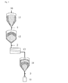
図1は、顆粒が反応器10から取り出され、バッファ容器11に移動されることを示す。次いで、顆粒は輸送コンテナ12に移され、スクリーニング設備13に輸送される。次いで、顆粒はバッファ容器14に再び移動され、最終的に15に包装される。
FIG. 1 shows that the granules are removed from the
バッファ容器11から輸送コンテナ12への移動は、最初の移動1に対応する。
The movement from the
(スクリーニング設備を介しての)輸送コンテナからバッファ容器への移動は、2回目の移動2に対応する。
The movement from the transport container (via the screening facility) to the buffer container corresponds to the
バッファ容器から包装設備への移動は、3回目の移動3に対応する。
The movement from the buffer container to the packaging facility corresponds to the
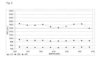
図2から5は、開始時(反応器からの取り出し後第1のバッファ容器、図2)および3回の移動操作の各々の後の粒子分離を示す。 Figures 2 to 5 show the particle separation at the start (first buffer vessel after removal from the reactor, Fig. 2) and after each of the three transfer operations.
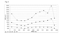
分離は、取り出されたバルクSi材料の量の関数として、粒子パラメータ×10、×50(中央値)および×90のプロットを使用して示される。 Separation is shown using plots of particle parameters x10, x50 (median) and x90 as a function of the amount of bulk Si material removed.
見出された結果に基づき、(大きな記号で網掛けされた)粗い材料および(小さな記号で網掛けされた)微細材料の層が図1に示される。 Based on the results found, a layer of coarse material (shaded with large symbols) and fine material (shaded with small symbols) is shown in FIG.
最初の移動1の後、かなりの粒子分離が存在する。図3を参照されたい。中央値(×50)のプロットは980μmから始まる。320kgの排出量までに、値は670μmまで低下する。その後、約880kgの取り出し量までに値は1300μmに上昇し、その後さらなる60kgにおいて約720μmまで低下する。 There is significant particle separation after the first transfer 1. Please refer to FIG. The median (× 50) plot begins at 980 μm. By 320 kg discharge, the value drops to 670 μm. The value then rises to 1300 μm by about 880 kg removal and then drops to about 720 μm at a further 60 kg.
2回目の移動2の後、粒子分離はすでにあまり目立たない。図4を参照されたい。中央値は、約160kgの量が取り出された後、最初にほぼ840から650μmに落下する。その後続く300kg以内で、中央値は1100μm超過へと非常に大幅に再び上昇する。460kgからは、中央値は約790μmまで低下する。残りの150kgで、中央値は、920μm超過へともう一度上昇する。
After the
3回目の移動3の後、バッチ全体にわたって比較的均質な粒子分布が存在する。図5を参照されたい。100kgの後、中央値は820から740μmへわずかしか低下せず、その後続く220kgにおいて上昇があって約1000μmに至る。500kgまでに、この値は900μmまで低下し、700kgまでに、1100μ超過まで上昇する。Siの残りの体積において、それは再び低下、約700μmの値に達する。
After the
容器の中心部にある材料が流出する最初である容器のファンネルフローを通じて、上部の粗い層が容器の外に移動操作の真ん中くらいで来る。粗い粒子および微粒子が再び混ざり合うので、製造バッチの部分的な逆混合が明らかに存在する。 Through the container funnel flow, the first outflow of material in the center of the container, the upper coarse layer comes out of the container about the middle of the transfer operation. There is clearly a partial backmixing of the production batch as the coarse and fine particles are mixed again.
Claims (5)
Applications Claiming Priority (3)
| Application Number | Priority Date | Filing Date | Title |
|---|---|---|---|
| DE102014200080.7 | 2014-01-08 | ||
| DE102014200080.7A DE102014200080A1 (en) | 2014-01-08 | 2014-01-08 | Process for producing granular polysilicon |
| PCT/EP2014/077323 WO2015104127A1 (en) | 2014-01-08 | 2014-12-11 | Method for producing granular polysilicon |
Publications (2)
| Publication Number | Publication Date |
|---|---|
| JP2017509571A true JP2017509571A (en) | 2017-04-06 |
| JP6219529B2 JP6219529B2 (en) | 2017-10-25 |
Family
ID=52144667
Family Applications (1)
| Application Number | Title | Priority Date | Filing Date |
|---|---|---|---|
| JP2016545342A Active JP6219529B2 (en) | 2014-01-08 | 2014-12-11 | Method for producing granular polysilicon |
Country Status (12)
| Country | Link |
|---|---|
| US (1) | US10118830B2 (en) |
| EP (1) | EP3092197B1 (en) |
| JP (1) | JP6219529B2 (en) |
| KR (1) | KR101889845B1 (en) |
| CN (1) | CN105939964B (en) |
| CA (1) | CA2935274C (en) |
| DE (1) | DE102014200080A1 (en) |
| ES (1) | ES2641189T3 (en) |
| MY (1) | MY179470A (en) |
| SA (1) | SA516371429B1 (en) |
| TW (1) | TWI579234B (en) |
| WO (1) | WO2015104127A1 (en) |
Families Citing this family (3)
| Publication number | Priority date | Publication date | Assignee | Title |
|---|---|---|---|---|
| DE102016204651A1 (en) | 2016-03-21 | 2017-09-21 | Wacker Chemie Ag | Crimp sleeves for the production of polysilicon granules |
| US10040637B2 (en) * | 2016-10-25 | 2018-08-07 | Rec Silicon Inc | Oscillatory feeder |
| CN114229847B (en) * | 2021-12-15 | 2023-09-22 | 浙江中控技术股份有限公司 | Parameter configuration method and device for polycrystalline silicon reduction furnace, terminal equipment and medium |
Citations (5)
| Publication number | Priority date | Publication date | Assignee | Title |
|---|---|---|---|---|
| US3369798A (en) * | 1965-12-13 | 1968-02-20 | A & T Development Corp | Apparatus for and method of blending dry materials |
| US5791493A (en) * | 1996-07-26 | 1998-08-11 | Memc Electronic Materials, Inc. | Polysilicon particle classifying apparatus |
| US20020159329A1 (en) * | 2000-09-07 | 2002-10-31 | Johanson Jerry R. | Racetrack-shaped dynamic gravity flow blender |
| JP2008503423A (en) * | 2004-06-18 | 2008-02-07 | エムイーエムシー・エレクトロニック・マテリアルズ・インコーポレイテッド | Method and system for producing granular material and method and system for reducing and measuring dust components in granular material |
| JP2013234113A (en) * | 2012-05-07 | 2013-11-21 | Wacker Chemie Ag | Granular polycrystalline silicon and generation of the same |
Family Cites Families (5)
| Publication number | Priority date | Publication date | Assignee | Title |
|---|---|---|---|---|
| FR448704A (en) * | 1911-07-25 | 1913-02-08 | Alphonse Busschodts | Mixer for compound chemical fertilizers |
| GB1084863A (en) * | 1965-01-06 | 1967-09-27 | Grafton Magna Ltd | Improvements in or relating to adjustable supports |
| JPH06127928A (en) * | 1992-10-20 | 1994-05-10 | Tonen Chem Corp | Production of granular polycrystalline silicon |
| DE102009028166A1 (en) | 2009-07-31 | 2011-02-03 | Wacker Chemie Ag | Method of conveying silicon granules in an encapsulated conveyor trough |
| CN102671582B (en) * | 2011-05-11 | 2015-04-08 | 储晞 | Reactor and method for producing particle materials |
-
2014
- 2014-01-08 DE DE102014200080.7A patent/DE102014200080A1/en not_active Withdrawn
- 2014-12-11 US US15/109,556 patent/US10118830B2/en active Active
- 2014-12-11 KR KR1020167018024A patent/KR101889845B1/en active Active
- 2014-12-11 CA CA2935274A patent/CA2935274C/en not_active Expired - Fee Related
- 2014-12-11 ES ES14816191.2T patent/ES2641189T3/en active Active
- 2014-12-11 MY MYPI2016001168A patent/MY179470A/en unknown
- 2014-12-11 EP EP14816191.2A patent/EP3092197B1/en active Active
- 2014-12-11 CN CN201480072665.1A patent/CN105939964B/en active Active
- 2014-12-11 JP JP2016545342A patent/JP6219529B2/en active Active
- 2014-12-11 WO PCT/EP2014/077323 patent/WO2015104127A1/en not_active Ceased
-
2015
- 2015-01-06 TW TW104100191A patent/TWI579234B/en active
-
2016
- 2016-06-28 SA SA516371429A patent/SA516371429B1/en unknown
Patent Citations (5)
| Publication number | Priority date | Publication date | Assignee | Title |
|---|---|---|---|---|
| US3369798A (en) * | 1965-12-13 | 1968-02-20 | A & T Development Corp | Apparatus for and method of blending dry materials |
| US5791493A (en) * | 1996-07-26 | 1998-08-11 | Memc Electronic Materials, Inc. | Polysilicon particle classifying apparatus |
| US20020159329A1 (en) * | 2000-09-07 | 2002-10-31 | Johanson Jerry R. | Racetrack-shaped dynamic gravity flow blender |
| JP2008503423A (en) * | 2004-06-18 | 2008-02-07 | エムイーエムシー・エレクトロニック・マテリアルズ・インコーポレイテッド | Method and system for producing granular material and method and system for reducing and measuring dust components in granular material |
| JP2013234113A (en) * | 2012-05-07 | 2013-11-21 | Wacker Chemie Ag | Granular polycrystalline silicon and generation of the same |
Also Published As
| Publication number | Publication date |
|---|---|
| CA2935274C (en) | 2018-01-02 |
| MY179470A (en) | 2020-11-06 |
| US10118830B2 (en) | 2018-11-06 |
| CA2935274A1 (en) | 2015-07-16 |
| TWI579234B (en) | 2017-04-21 |
| WO2015104127A1 (en) | 2015-07-16 |
| EP3092197B1 (en) | 2017-08-09 |
| DE102014200080A1 (en) | 2015-07-09 |
| KR20160093715A (en) | 2016-08-08 |
| SA516371429B1 (en) | 2019-02-26 |
| ES2641189T3 (en) | 2017-11-08 |
| JP6219529B2 (en) | 2017-10-25 |
| KR101889845B1 (en) | 2018-08-20 |
| CN105939964A (en) | 2016-09-14 |
| EP3092197A1 (en) | 2016-11-16 |
| CN105939964B (en) | 2018-04-13 |
| US20160326001A1 (en) | 2016-11-10 |
| TW201527214A (en) | 2015-07-16 |
Similar Documents
| Publication | Publication Date | Title |
|---|---|---|
| KR101830856B1 (en) | Method for producing high-purity granular silicon | |
| JPH067700A (en) | Jet grinding method for silicon particles | |
| CN101006008B (en) | Systems and methods for producing granular material and for measuring and reducing dust in granular material | |
| JP6246905B2 (en) | Reactor for producing polycrystalline silicon and a method for removing a silicon-containing layer on components of such a reactor | |
| JP2011526877A (en) | Fluidized bed reactor system and method for reducing silicon deposition on reactor wall | |
| CN102639438B (en) | Reactor and method for producing silicon | |
| CN103842069B (en) | Polysilicon is prepared by making silane thermally decompose in a fluidized bed reactor | |
| JP2013224254A (en) | Particulate polycrystal silicon, and manufacture of the same | |
| CN102671581A (en) | Method and reactor for producing particle materials | |
| JP6219529B2 (en) | Method for producing granular polysilicon | |
| CN105658577A (en) | Fluidized bed reactor and method for producing granular polysilicon | |
| CN105189350B (en) | Fluidized-bed reactor and the method for producing granulated polycrystalline silicon | |
| EP2310317A1 (en) | Methods for increasing polycrystalline silicon reactor productivity by recycle of silicon fines | |
| CN107253723A (en) | Polysilicon is prepared by making silane thermally decompose in a fluidized bed reactor | |
| CN105026029B (en) | Improved Fluid Bed Reactor Operation by Optimizing Temperature Gradients with Particle Size Distribution Control | |
| KR101739370B1 (en) | Method of preparing feed seed for granular polycrystalline polysilicon preparation | |
| WO2017172748A1 (en) | Systems and methods for dust suppressed silicon charging in a vacuum | |
| EP3636633B1 (en) | Pneumatic conveyance method for methionine | |
| JPH04224195A (en) | Improved polysilicon and method therefor |
Legal Events
| Date | Code | Title | Description |
|---|---|---|---|
| A529 | Written submission of copy of amendment under article 34 pct |
Free format text: JAPANESE INTERMEDIATE CODE: A529 Effective date: 20160902 |
|
| A621 | Written request for application examination |
Free format text: JAPANESE INTERMEDIATE CODE: A621 Effective date: 20160902 |
|
| A977 | Report on retrieval |
Free format text: JAPANESE INTERMEDIATE CODE: A971007 Effective date: 20170810 |
|
| TRDD | Decision of grant or rejection written | ||
| A01 | Written decision to grant a patent or to grant a registration (utility model) |
Free format text: JAPANESE INTERMEDIATE CODE: A01 Effective date: 20170829 |
|
| A61 | First payment of annual fees (during grant procedure) |
Free format text: JAPANESE INTERMEDIATE CODE: A61 Effective date: 20170927 |
|
| R150 | Certificate of patent or registration of utility model |
Ref document number: 6219529 Country of ref document: JP Free format text: JAPANESE INTERMEDIATE CODE: R150 |
|
| R250 | Receipt of annual fees |
Free format text: JAPANESE INTERMEDIATE CODE: R250 |
|
| R250 | Receipt of annual fees |
Free format text: JAPANESE INTERMEDIATE CODE: R250 |
|
| R250 | Receipt of annual fees |
Free format text: JAPANESE INTERMEDIATE CODE: R250 |
|
| R250 | Receipt of annual fees |
Free format text: JAPANESE INTERMEDIATE CODE: R250 |
|
| R250 | Receipt of annual fees |
Free format text: JAPANESE INTERMEDIATE CODE: R250 |
|
| R250 | Receipt of annual fees |
Free format text: JAPANESE INTERMEDIATE CODE: R250 |