JP2017516965A - Cylindrical gear transmission - Google Patents
Cylindrical gear transmission Download PDFInfo
- Publication number
- JP2017516965A JP2017516965A JP2017513348A JP2017513348A JP2017516965A JP 2017516965 A JP2017516965 A JP 2017516965A JP 2017513348 A JP2017513348 A JP 2017513348A JP 2017513348 A JP2017513348 A JP 2017513348A JP 2017516965 A JP2017516965 A JP 2017516965A
- Authority
- JP
- Japan
- Prior art keywords
- cylindrical gear
- cylindrical
- surrounding wall
- gear transmission
- gears
- Prior art date
- Legal status (The legal status is an assumption and is not a legal conclusion. Google has not performed a legal analysis and makes no representation as to the accuracy of the status listed.)
- Granted
Links
Images



Classifications
-
- F—MECHANICAL ENGINEERING; LIGHTING; HEATING; WEAPONS; BLASTING
- F16—ENGINEERING ELEMENTS AND UNITS; GENERAL MEASURES FOR PRODUCING AND MAINTAINING EFFECTIVE FUNCTIONING OF MACHINES OR INSTALLATIONS; THERMAL INSULATION IN GENERAL
- F16H—GEARING
- F16H57/00—General details of gearing
- F16H57/04—Features relating to lubrication or cooling or heating
- F16H57/0409—Features relating to lubrication or cooling or heating characterised by increasing efficiency, e.g. by reducing splash losses
-
- F—MECHANICAL ENGINEERING; LIGHTING; HEATING; WEAPONS; BLASTING
- F16—ENGINEERING ELEMENTS AND UNITS; GENERAL MEASURES FOR PRODUCING AND MAINTAINING EFFECTIVE FUNCTIONING OF MACHINES OR INSTALLATIONS; THERMAL INSULATION IN GENERAL
- F16H—GEARING
- F16H1/00—Toothed gearings for conveying rotary motion
- F16H1/02—Toothed gearings for conveying rotary motion without gears having orbital motion
- F16H1/04—Toothed gearings for conveying rotary motion without gears having orbital motion involving only two intermeshing members
- F16H1/06—Toothed gearings for conveying rotary motion without gears having orbital motion involving only two intermeshing members with parallel axes
-
- F—MECHANICAL ENGINEERING; LIGHTING; HEATING; WEAPONS; BLASTING
- F16—ENGINEERING ELEMENTS AND UNITS; GENERAL MEASURES FOR PRODUCING AND MAINTAINING EFFECTIVE FUNCTIONING OF MACHINES OR INSTALLATIONS; THERMAL INSULATION IN GENERAL
- F16H—GEARING
- F16H57/00—General details of gearing
- F16H57/04—Features relating to lubrication or cooling or heating
- F16H57/0412—Cooling or heating; Control of temperature
- F16H57/0415—Air cooling or ventilation; Heat exchangers; Thermal insulations
-
- F—MECHANICAL ENGINEERING; LIGHTING; HEATING; WEAPONS; BLASTING
- F16—ENGINEERING ELEMENTS AND UNITS; GENERAL MEASURES FOR PRODUCING AND MAINTAINING EFFECTIVE FUNCTIONING OF MACHINES OR INSTALLATIONS; THERMAL INSULATION IN GENERAL
- F16H—GEARING
- F16H57/00—General details of gearing
- F16H57/04—Features relating to lubrication or cooling or heating
- F16H57/0412—Cooling or heating; Control of temperature
- F16H57/0415—Air cooling or ventilation; Heat exchangers; Thermal insulations
- F16H57/0416—Air cooling or ventilation
-
- F—MECHANICAL ENGINEERING; LIGHTING; HEATING; WEAPONS; BLASTING
- F16—ENGINEERING ELEMENTS AND UNITS; GENERAL MEASURES FOR PRODUCING AND MAINTAINING EFFECTIVE FUNCTIONING OF MACHINES OR INSTALLATIONS; THERMAL INSULATION IN GENERAL
- F16H—GEARING
- F16H57/00—General details of gearing
- F16H57/04—Features relating to lubrication or cooling or heating
- F16H57/0412—Cooling or heating; Control of temperature
- F16H57/0415—Air cooling or ventilation; Heat exchangers; Thermal insulations
- F16H57/0417—Heat exchangers adapted or integrated in the gearing
-
- F—MECHANICAL ENGINEERING; LIGHTING; HEATING; WEAPONS; BLASTING
- F16—ENGINEERING ELEMENTS AND UNITS; GENERAL MEASURES FOR PRODUCING AND MAINTAINING EFFECTIVE FUNCTIONING OF MACHINES OR INSTALLATIONS; THERMAL INSULATION IN GENERAL
- F16H—GEARING
- F16H57/00—General details of gearing
- F16H57/04—Features relating to lubrication or cooling or heating
- F16H57/042—Guidance of lubricant
- F16H57/0421—Guidance of lubricant on or within the casing, e.g. shields or baffles for collecting lubricant, tubes, pipes, grooves, channels or the like
- F16H57/0423—Lubricant guiding means mounted or supported on the casing, e.g. shields or baffles for collecting lubricant, tubes or pipes
-
- F—MECHANICAL ENGINEERING; LIGHTING; HEATING; WEAPONS; BLASTING
- F16—ENGINEERING ELEMENTS AND UNITS; GENERAL MEASURES FOR PRODUCING AND MAINTAINING EFFECTIVE FUNCTIONING OF MACHINES OR INSTALLATIONS; THERMAL INSULATION IN GENERAL
- F16H—GEARING
- F16H57/00—General details of gearing
- F16H57/04—Features relating to lubrication or cooling or heating
- F16H57/0434—Features relating to lubrication or cooling or heating relating to lubrication supply, e.g. pumps; Pressure control
- F16H57/0436—Pumps
-
- F—MECHANICAL ENGINEERING; LIGHTING; HEATING; WEAPONS; BLASTING
- F16—ENGINEERING ELEMENTS AND UNITS; GENERAL MEASURES FOR PRODUCING AND MAINTAINING EFFECTIVE FUNCTIONING OF MACHINES OR INSTALLATIONS; THERMAL INSULATION IN GENERAL
- F16H—GEARING
- F16H57/00—General details of gearing
- F16H57/04—Features relating to lubrication or cooling or heating
- F16H57/0456—Lubrication by injection; Injection nozzles or tubes therefor
-
- F—MECHANICAL ENGINEERING; LIGHTING; HEATING; WEAPONS; BLASTING
- F16—ENGINEERING ELEMENTS AND UNITS; GENERAL MEASURES FOR PRODUCING AND MAINTAINING EFFECTIVE FUNCTIONING OF MACHINES OR INSTALLATIONS; THERMAL INSULATION IN GENERAL
- F16H—GEARING
- F16H57/00—General details of gearing
- F16H57/04—Features relating to lubrication or cooling or heating
- F16H57/048—Type of gearings to be lubricated, cooled or heated
- F16H57/0493—Gearings with spur or bevel gears
- F16H57/0495—Gearings with spur or bevel gears with fixed gear ratio
Landscapes
- Engineering & Computer Science (AREA)
- General Engineering & Computer Science (AREA)
- Mechanical Engineering (AREA)
- General Details Of Gearings (AREA)
- Gear Transmission (AREA)
Abstract
本発明は、円筒歯車伝動装置であって、歯列を有する少なくとも2つの円筒歯車(1,2)を備え、該円筒歯車の前記歯列は、互いに噛み合った状態で係合しており、前記円筒歯車は、それぞれ1つの回転軸線(3,4)を中心として回転可能であり、両方の前記円筒歯車を周方向でかつ前記回転軸線の方向で取り囲む包囲壁(5)を備え、該包囲壁は、該包囲壁と前記円筒歯車との間に、互いに移行し合う2つの環状ギャップ(6,7)が形成されるように、前記円筒歯車の外径に適合された内側輪郭を有し、それぞれ1つの前記環状ギャップは、前記それぞれ1つの回転軸線に対して少なくともほぼ同心に配置されており、前記包囲壁は、前記両方の円筒歯車を前記周方向でその全周の一部にわたってのみ取り囲んでおり、これによって、前記両方の円筒歯車の外周の一部または前記両方の円筒歯車のうちの少なくとも一方の円筒歯車の外周の一部が、前記包囲壁を越えて外方に突出している、円筒歯車伝動装置に関する。本発明に係る円筒歯車伝動装置は、前記両方の円筒歯車または前記一方の円筒歯車の、前記包囲壁を越えて突出した前記一部が、前記円筒歯車のうちの下側に位置決めされていることを特徴としている。The present invention is a cylindrical gear transmission, comprising at least two cylindrical gears (1, 2) having tooth rows, and the tooth rows of the cylindrical gears are engaged with each other in mesh with each other, Each cylindrical gear is rotatable about one rotation axis (3, 4), and includes a surrounding wall (5) that surrounds both the cylindrical gears in the circumferential direction and in the direction of the rotation axis. Has an inner profile adapted to the outer diameter of the cylindrical gear such that two annular gaps (6, 7) are formed between the surrounding wall and the cylindrical gear, which transition to each other. Each one said annular gap is arranged at least approximately concentrically with respect to each said one rotational axis, and said surrounding wall surrounds both said cylindrical gears in said circumferential direction only over part of their entire circumference And by this Part of the outer periphery of at least one of the cylindrical gear of the cylindrical gear part or the both of the outer periphery of the both cylindrical gear projects outward beyond the surrounding wall, to the cylindrical gear transmission. In the cylindrical gear transmission according to the present invention, the part of both the cylindrical gears or the one cylindrical gear that protrudes beyond the surrounding wall is positioned below the cylindrical gear. It is characterized by.
Description
本発明は、歯列を有する少なくとも2つの円筒歯車を備えた円筒歯車伝動装置、詳細には、独立請求項の上位概念部に記載した円筒歯車伝動装置に関する。 The present invention relates to a cylindrical gear transmission provided with at least two cylindrical gears having tooth rows, and in particular, to a cylindrical gear transmission described in a superordinate concept section of an independent claim.
冒頭に記載した形態の円筒歯車伝動装置は、たとえば国際公開第2012/028231号に基づき公知である。このような円筒歯車伝動装置は、たとえば高回転型の伝動装置、たとえばターボ伝動装置として形成されている。 A cylindrical gear transmission of the form described at the beginning is known, for example, on the basis of WO 2012/028231. Such a cylindrical gear transmission is formed, for example, as a high rotation type transmission, for example, a turbo transmission.
特にこのような高回転型の伝動装置、たとえばターボ伝動装置では、伝動装置ハウジングの内室内で空気・油混合物に渦流が発生することに基づき、望ましくない損失が生じてしまう。この損失を減少させるために、種々異なる手段が公知である。1つの手段は、伝動装置ハウジングの内室を真空ポンプによって吸引することを特定しており、これによって、内室内の圧力が、伝動装置ハウジングの外部の周辺の圧力よりも低くなる。 In particular, in such a high-rotation type transmission device, for example, a turbo transmission device, an undesirable loss occurs due to the vortex generated in the air / oil mixture in the inner chamber of the transmission housing. Different means are known for reducing this loss. One means specifies that the inner chamber of the transmission housing is sucked by a vacuum pump, so that the pressure in the inner chamber is lower than the pressure around the outside of the transmission housing.
伝動装置ハウジングのこのような吸引を回避すべき別の手段、つまり、円筒歯車を取り囲むように密接する包囲壁を設けることが、冒頭に記載した国際公開第2012/028231号に図示されている。包囲壁は周方向において、流入ギャップと、場合によっては、円筒歯車の外周の範囲外に位置決めされた流出ギャップとを除いて、円筒歯車を取り囲んでいる。包囲壁による円筒歯車のこの包込みも、円筒歯車の外径の領域もしくは円筒歯車の歯列の領域に、損失を減少させる負圧を発生させるために特定されている。 Another means to avoid such suction of the transmission housing, namely the provision of an enclosing wall that closely surrounds the cylindrical gear, is illustrated in WO 2012/028231 mentioned at the beginning. The surrounding wall surrounds the cylindrical gear in the circumferential direction except for the inflow gap and, in some cases, the outflow gap positioned outside the outer periphery of the cylindrical gear. This enclosing of the cylindrical gear by the surrounding wall has also been specified to generate a negative pressure in the outer diameter region of the cylindrical gear or in the region of the dentition of the cylindrical gear that reduces the loss.
したがって、公知の両手段は、損失出力を減少させるために、円筒歯車の周方向に設けられた歯列の領域に、可能な限り低い圧力、すなわち、可能な限り強い真空が発生させられなければならないという想定に基づいている。ゆえに、真空を可能な限り最適化するために、十分な密封のための相当に手間のかかる手段もしくは比較的強出力のひいては高価でエネルギ集約的な真空ポンプが設けられている。 Therefore, both known means must be able to generate the lowest possible pressure, i.e. the strongest possible vacuum, in the region of the dentition provided in the circumferential direction of the cylindrical gear in order to reduce the loss output. It is based on the assumption that it will not be. Therefore, in order to optimize the vacuum as much as possible, a fairly laborious means for sufficient sealing or a relatively strong output and thus an expensive and energy intensive vacuum pump is provided.
独国特許第19860353号明細書には、円筒歯車伝動装置が開示されている。この円筒歯車伝動装置では、円筒歯車が、主ハウジングの内部に固定された付加的な内側ハウジングによって取り囲まれる。この内側ハウジングの内室には、ポンプによって部分真空が発生させられる。内側ハウジングと主ハウジングとの間の室は大気圧下にある。円筒歯車は、内側ハウジングを越えて外方に突出しておらず、この内側ハウジングから間隔を置いて取り囲まれ、これによって、互いに移行し合う環状ギャップも形成されていない。 German patent specification No. 19860353 discloses a cylindrical gear transmission. In this cylindrical gear transmission, the cylindrical gear is surrounded by an additional inner housing fixed inside the main housing. A partial vacuum is generated in the inner chamber of the inner housing by a pump. The chamber between the inner housing and the main housing is at atmospheric pressure. The cylindrical gear does not protrude outward beyond the inner housing and is surrounded at a distance from the inner housing, thereby forming no annular gaps that transition from one another.
独国特許出願公開第102006022964号明細書には、流体補償容器と、この流体補償容器を備えた伝動装置とが記載されている。流体補償容器は、円筒歯車を側方でその全周の一部にわたって取り囲んでいる。 German Offenlegungsschrift 102006022964 describes a fluid compensation container and a transmission device comprising this fluid compensation container. The fluid compensation container surrounds the cylindrical gear laterally over a part of its entire circumference.
独国特許出願公開第102007041318号明細書には、歯車ポンプを備えた手動変速機が記載されている。歯車ポンプは外接歯車ポンプであり、互いに噛み合う2つの歯車を有している。両歯車のうち、一方の歯車は、変速機内の複数の歯車セットのうちの1つの歯車セットに含まれている。圧送ギャップを形成するために、歯車の下側に付加的なハウジングが設けられている。このハウジングは歯車の全周の一部にわたって延在している。 German Offenlegungsschrift 102007041318 describes a manual transmission with a gear pump. The gear pump is a circumscribed gear pump and has two gears that mesh with each other. One of the two gears is included in one gear set of a plurality of gear sets in the transmission. In order to form a pumping gap, an additional housing is provided under the gear. This housing extends over part of the entire circumference of the gear.
英国特許出願公告第292540号明細書には、ハウジング内で高い回転数で回転する歯車が記載されている。この歯車には、その潤滑を改善するために、特別なガイドが対応配置されている。このガイドは歯車を部分的に取り囲んでいて、この歯車がガイドを越えて突出しないように、下側で少なくとも閉鎖されている。 GB-A-292540 describes a gear that rotates at a high rotational speed in a housing. In order to improve the lubrication of this gear, a special guide is arranged correspondingly. The guide partially surrounds the gear and is at least closed on the underside so that the gear does not protrude beyond the guide.
英国特許出願公告第1426352号明細書には、歯車のための潤滑装置が記載されている。同明細書でも同じく、部分的に開放された内側ハウジングが設けられている。この内側ハウジングは、歯車をその下側でかつ一方の側方の側で狭幅を置いて取り囲んでいる。 British Patent Application Publication No. 1426352 describes a lubrication device for gears. The same specification also provides a partially open inner housing. The inner housing surrounds the gear wheel with a narrow width on its lower side and on one side.
英国特許出願公告第458379号明細書には、伝動装置内に組み込まれたエアポンプが開示されている。このエアポンプは、歯車をその端面側で閉じ込めるガイド湾曲部を有している。 British Patent Application Publication No. 458379 discloses an air pump incorporated in a transmission. This air pump has a guide curved portion for confining the gear on its end face side.
米国特許出願公開第2014/0054114号明細書には、伝動装置のための潤滑油供給部が開示されている。同明細書では、1つのカバーが、2つの円筒歯車のうちのピニオンを完全に取り囲んでいて、両歯車のうちの他方の歯車を半周にわたって取り囲んでいる。 U.S. Patent Application Publication No. 2014/0054114 discloses a lubricating oil supply for a transmission. In this specification, one cover completely surrounds the pinion of the two cylindrical gears, and surrounds the other of the two gears over a half circumference.
米国特許第5950501号明細書には、円筒歯車伝動装置が示されている。この円筒歯車伝動装置の内側ハウジングは、円筒歯車を所定の間隔を置いて取り囲んでいて、ポンプによって排気されるかまたはガスで満たされる。互いに移行し合う環状ギャップは設けられておらず、円筒歯車は内側ハウジングを越えて突出していない。 U.S. Pat. No. 5,950,501 shows a cylindrical gear transmission. The inner housing of the cylindrical gear transmission surrounds the cylindrical gear at a predetermined interval and is evacuated or filled with gas by a pump. There are no annular gaps to transition to each other, and the cylindrical gear does not protrude beyond the inner housing.
米国特許第2645305号明細書には、伝動装置の円筒歯車のための潤滑装置が記載されている。伝動装置は円筒歯車の側方の遮蔽部を備えている。この遮蔽部は円筒歯車の外周の小さな部分にわたってしか突出していない。 U.S. Pat. No. 2,645,305 describes a lubricating device for a cylindrical gear of a transmission. The transmission device includes a side shield portion of the cylindrical gear. This shielding part protrudes only over a small part of the outer periphery of the cylindrical gear.
欧州特許出願公開第2535618号明細書には、ハウジングにより取り囲まれた円筒歯車が開示されている。しかしながら、この円筒歯車はハウジングを越えて突出していない。 EP 2535618 discloses a cylindrical gear surrounded by a housing. However, this cylindrical gear does not protrude beyond the housing.
国際公開第2012/028231号には、包囲壁を備えた歯車伝動装置が開示されている。包囲壁は、互いに協働する2つの歯車のうちの少なくとも一方を取り囲んでいて、取り囲まれた内室を部分的にまたは完全に周辺に対して遮断している。歯車は包囲壁を越えて突出していない。 International Publication No. 2012/028231 discloses a gear transmission having a surrounding wall. The surrounding wall surrounds at least one of the two gears cooperating with each other, and partially or completely blocks the enclosed inner chamber from the periphery. The gear does not protrude beyond the surrounding wall.
特開2011−163365号公報には、歯車の形状に部分的に適合された油通路を備えた歯車伝動装置が開示されている。 Japanese Patent Application Laid-Open No. 2011-163365 discloses a gear transmission provided with an oil passage partially adapted to the shape of the gear.
本発明の課題は、冒頭に記載した形態の円筒歯車伝動装置を改良して、少ない製造・保守コストで高い効率が達成されるようにする、すなわち、損失出力を減少させるための手段が、1つには有効であり、もう1つには廉価であるようにすることである。 The object of the present invention is to improve the cylindrical gear transmission of the form described at the outset so that high efficiency is achieved with low production and maintenance costs, i.e. means for reducing the loss output is 1 One is effective and the other is inexpensive.
本発明による課題は、独立請求項に記載の円筒歯車伝動装置によって解決される。従属請求項には、本発明の有利なかつ特に好適な態様が記載してある。 The object according to the invention is solved by a cylindrical gear transmission according to the independent claims. The dependent claims contain advantageous and particularly preferred embodiments of the invention.
本発明に係る円筒歯車伝動装置は、歯列を有する少なくとも2つの円筒歯車を有している。これらの円筒歯車の歯列は、互いに噛み合った状態で係合している。両円筒歯車は、それぞれ1つの回転軸線を中心として回転可能である。円筒歯車伝動装置は、両円筒歯車を周方向でかつ回転軸線の方向で取り囲む包囲壁を有している。この包囲壁は、この包囲壁と円筒歯車との間に、互いに移行し合う2つの環状ギャップが形成されるように、円筒歯車の外径に適合された内側輪郭を有している。それぞれ1つの環状ギャップは、それぞれ1つの回転軸線に対して少なくともほぼ同心に配置されている。 The cylindrical gear transmission according to the present invention has at least two cylindrical gears having tooth rows. The tooth rows of these cylindrical gears are engaged with each other while meshing with each other. Both cylindrical gears are rotatable around one rotation axis. The cylindrical gear transmission has an enclosing wall that surrounds both cylindrical gears in the circumferential direction and in the direction of the rotational axis. The enclosing wall has an inner contour adapted to the outer diameter of the cylindrical gear so that two annular gaps are formed between the enclosing wall and the cylindrical gear so as to transition from each other. Each one annular gap is arranged at least approximately concentrically with respect to each rotation axis.
本発明による第1の態様によれば、包囲壁が、両円筒歯車を周方向でその全周の一部にわたってのみ取り囲んでおり、これによって、両円筒歯車の外周の一部または両円筒歯車のうちの少なくとも一方の円筒歯車の外周の一部が、包囲壁を越えて外方に突出している。したがって、全周のうちの、包囲壁を越えて外方に突出した部分が、包囲壁の周辺、たとえば円筒歯車伝動装置の伝動装置ハウジングの内室に対して露出している。ゆえに、前述した先行技術のような、円筒歯車の完全な包込みは行われていない。全周のうちの、包囲壁を越えて外方に突出した部分は、両円筒歯車が相並んで位置決めされている場合には、円筒歯車の外周に沿って位置決めされた包囲壁部分の、円筒歯車の回転軸線に対して垂直な横断面により形成される投影面の範囲外に位置している。言い換えると、包囲壁が、円筒歯車を包囲壁の周辺から、いわば視認できるようにする、円筒歯車の範囲にわたる開口を有しているだけでなく、円筒歯車が、実際には、包囲壁の相応の開口から突出していて、この開口を越えて張り出している。両円筒歯車が互いに重なり合って位置決めされている場合には、相応して、上側の円筒歯車から下側の円筒歯車に向かって下方に延在する包囲壁が終端している水平な平面を越えて、下側の円筒歯車が下方に突出している。 According to the first aspect of the present invention, the surrounding wall surrounds both the cylindrical gears in a circumferential direction only over a part of the entire circumference thereof, whereby a part of the outer periphery of the two cylindrical gears or the two cylindrical gears. A part of the outer periphery of at least one of the cylindrical gears protrudes outward beyond the surrounding wall. Therefore, a portion of the entire circumference that protrudes outward beyond the surrounding wall is exposed to the periphery of the surrounding wall, for example, the inner chamber of the transmission housing of the cylindrical gear transmission. Therefore, the cylindrical gear is not completely encased as in the prior art described above. The portion of the entire circumference that protrudes outward beyond the surrounding wall is the cylinder of the surrounding wall portion that is positioned along the outer periphery of the cylindrical gear when both cylindrical gears are positioned side by side. It lies outside the range of the projection plane formed by the cross section perpendicular to the rotational axis of the gear. In other words, the encircling wall not only has an opening over the range of the cylindrical gear that makes the cylindrical gear visible from the perimeter of the encircling wall, so to speak, but the cylindrical gear is actually the equivalent of the enclosing wall. It protrudes from the opening and projects beyond this opening. If both cylindrical gears are positioned so as to overlap each other, correspondingly beyond the horizontal plane where the surrounding wall terminates downwardly from the upper cylindrical gear towards the lower cylindrical gear. The lower cylindrical gear protrudes downward.
両方の円筒歯車または一方の円筒歯車の、包囲壁を越えて突出した部分は、円筒歯車のうちの下側に、すなわち、円筒歯車伝動装置の運転中、重力により円筒歯車伝動装置内の下側に集まる油溜めの方向に位置決めされている。これに対して、円筒歯車は、反対の上側では包囲壁によって、有利には完全に、特に各円筒歯車の全周の少なくとも上側半分にわたって取り囲まれる。この上側半分は下側で、特に水平線によって閉じられる。すなわち、包囲壁がその下面において水平な平面で終端している。円筒歯車が互いに重なり合って位置決めされていて、特に正確に2つの円筒歯車が設けられていて、両円筒歯車のうち、一方の円筒歯車が他方の円筒歯車の上方に位置決めされている場合には、たとえば、下側の円筒歯車が、少なくともほぼその回転軸線の高さで始まるかまたは回転軸線よりも下側の高さで始まって、少なくとも約少なくとも90°の弧にわたって取り囲まれていてもよく、その後、上側の円筒歯車が、有利には、包囲壁によって180°よりも大きい角度だけ、特に両歯列の噛合い領域の側方で始まって、引き続き、上向きで上側の円筒歯車の頂点を越えて反対の側に向かい、再び下向きで少なくともほぼ上側の円筒歯車の回転軸線の高さにまで延在して、実質的に270°だけ取り囲まれていてもよい。 The portion of both cylindrical gears or one of the cylindrical gears that protrudes beyond the surrounding wall is on the lower side of the cylindrical gear, that is, the lower side in the cylindrical gear transmission due to gravity during operation of the cylindrical gear transmission. It is positioned in the direction of the oil sump that collects in On the other hand, the cylindrical gear is advantageously completely surrounded by the surrounding wall on the opposite upper side, in particular over at least the upper half of the entire circumference of each cylindrical gear. This upper half is closed on the lower side, in particular by a horizontal line. That is, the surrounding wall terminates in a horizontal plane on its lower surface. When the cylindrical gears are positioned so as to overlap each other, particularly when two cylindrical gears are provided and one of the cylindrical gears is positioned above the other cylindrical gear, For example, the lower cylindrical gear may be surrounded over an arc of at least about 90 °, starting at least approximately at the height of its rotational axis or starting at a lower level than its rotational axis. The upper cylindrical gear advantageously starts at an angle greater than 180 ° by the surrounding wall, in particular on the side of the meshing area of both dentitions and continues upward and beyond the top of the upper cylindrical gear It may be directed to the opposite side and again downwardly and at least approximately up to the height of the axis of rotation of the upper cylindrical gear, substantially surrounded by 270 °.
円筒歯車の、包囲壁を越えて下方に突出した部分、円筒歯車が互いに重なり合って位置決めされている場合には、下側の円筒歯車の、下方に突出した部分は、有利には、伝動装置内の油溜めの上方に、特に油溜めもしくは伝動装置ハウジングの下側の壁に対して間隔を置いて露出して位置決めされている。この間隔は、有利には、包囲壁と、1つまたはそれ以上の円筒歯車の取り囲まれた領域との間の間隔の複数倍である。 The part of the cylindrical gear that protrudes downward beyond the enclosure wall, if the cylindrical gears are positioned so as to overlap each other, the downwardly protruding part of the lower cylindrical gear is preferably in the transmission The oil reservoir is positioned above the oil sump, in particular at a distance from the sump or the lower wall of the transmission housing. This spacing is advantageously a multiple of the spacing between the surrounding wall and the enclosed area of one or more cylindrical gears.
しかしながら、本発明は、油溜めが伝動装置ハウジングの外側に設けられているかまたは別の適切な潤滑部によって相応の油溜めを省略することができる伝動装置の場合には、相応の手段でも適用可能である。 However, the invention can also be applied in a corresponding manner in the case of a transmission in which the oil sump is provided outside the transmission housing or the corresponding oil sump can be omitted by another suitable lubrication. It is.
両円筒歯車はその回転軸線でもって相並んで、有利には円筒歯車伝動装置の水平方向に位置決めされている。回転軸線は、特に1つの共通の水平な平面の内部に延びている。この平面は、特に円筒歯車伝動装置内の下側の油溜めの表面に対して平行である。 Both cylindrical gears are arranged side by side with their axis of rotation and are preferably positioned in the horizontal direction of the cylindrical gear transmission. The axis of rotation extends especially inside one common horizontal plane. This plane is in particular parallel to the surface of the lower sump in the cylindrical gear transmission.
有利には、包囲壁は、円筒歯車の回転軸線に対して垂直な鉛直な平面の横断面で見て、両円筒歯車をその上側半分にわたって完全にかつこれを越えて下側半分の一部にわたって取り囲んでいる。包囲体の、上側半分を越える両部分は、特にその自由端部において横断面先細りにされて形成されていてもよい。 Advantageously, the encircling wall, when viewed in a cross section of a vertical plane perpendicular to the axis of rotation of the cylindrical gear, covers both cylindrical gears completely over its upper half and beyond part of its lower half. Surrounding. Both parts of the enclosure beyond the upper half may be formed with a tapered cross section, in particular at its free end.
本発明の態様によれば、包囲体と円筒歯車の外径との間のギャップもしくは環状ギャップが、包囲体の自由端部において先細りにされて形成されている。このことは、包囲体の一方の自由端部または両方の自由端部において特定されていてもよい。このように、環状ギャップをその残りの領域に比べて減少させることによって、環状ギャップに対する油の望ましくない流出および/または流入を阻止するかまたは減少させる密封が達成される。 According to an aspect of the present invention, a gap or annular gap between the enclosure and the outer diameter of the cylindrical gear is formed to be tapered at the free end of the enclosure. This may be specified at one or both free ends of the enclosure. Thus, by reducing the annular gap relative to its remaining region, a seal is achieved that prevents or reduces undesired spillage and / or inflow of oil to the annular gap.
本発明の態様によれば、円筒歯車の噛合いの領域、特に両円筒歯車の上側における噛合いの領域が包囲体なしであるか、または包囲体に相応の窓が設けられている。 According to an aspect of the invention, the meshing area of the cylindrical gear, in particular the meshing area on the upper side of both cylindrical gears, is free of enclosures or is provided with a corresponding window.
本発明による第1の態様の根底には、回転する円筒歯車の歯列の領域に負圧もしくは真空を発生させることによって、損失出力を減少させることができるだけでなく、実際には、潤滑剤、特に潤滑油が遠心力によって外向きに投げ飛ばされるので、円筒歯車を取り囲むように、少量の潤滑剤媒体、特に少量の潤滑油媒体から成る薄膜の層も形成されるという知見がある。このような層または層形成は包囲壁によって安定化させられる。環状ギャップの幅を合目的的に選択することによって、包囲壁よりも外側には比較的多量の油媒体が存在していてもよいのに対して、包囲壁よりも内側、すなわち、円筒歯車と包囲壁との間の環状ギャップ内には、少量の油媒体が存在していることを確定することができる。したがって、完全な包込みなしでも、真空が発生させられなくても、加速させられなければならなくて、ひいては、円筒歯車の出力消費を高めてしまう多量の潤滑剤媒体が円筒歯車に達することが阻止される。 The basis of the first aspect according to the present invention is not only that the loss output can be reduced by generating a negative pressure or vacuum in the region of the dentition of the rotating cylindrical gear, but in fact the lubricant, In particular, since the lubricating oil is thrown outward by centrifugal force, there is a finding that a thin film layer composed of a small amount of lubricant medium, particularly a small amount of lubricating oil medium, is also formed so as to surround the cylindrical gear. Such a layer or layer formation is stabilized by the surrounding wall. By appropriately selecting the width of the annular gap, there may be a relatively large amount of oil medium outside the surrounding wall, whereas inside the surrounding wall, i.e. the cylindrical gear and It can be determined that there is a small amount of oil medium in the annular gap with the surrounding wall. Therefore, even if there is no complete envelopment, no vacuum is generated, it must be accelerated and, in turn, a large amount of lubricant medium that can increase the power consumption of the cylindrical gear can reach the cylindrical gear. Be blocked.
本発明による第1の解決手段は、包囲壁を取り囲む伝動装置ハウジングの内室に負圧が付加的に発生させられる、すなわち、内室内に伝動装置ハウジングの周辺よりも低い圧力が形成されることを排除していない。このような負圧は、たとえば外部のまたは組み込まれた真空ポンプによって発生させることができる。この真空ポンプの吸込み側は内室に接続されている。包囲壁の周辺圧をこのようにして減少させると、部分包込み型の内側ハウジング、すなわち、本発明による包囲壁によって、出力消費をさらに一層低減することができる。円筒歯車が部分的にまたは完全に包み込まれ(後者については以下でさらに説明する)、かつ伝動装置ハウジングの内室が付加的に減圧される本発明による態様の損失出力は、円筒歯車が包み込まれない、すなわち、包囲壁が設けられない伝動装置ハウジングの内室が吸引される態様に比べても低損失出力である。なぜならば、つまるところ、従来では、伝動装置ハウジング内の媒体のより少ない密度によって、上述したように、ほんの僅かしか層形成が行われず、これによって、多量の油媒体が円筒歯車の歯列により容易に達してしまうからである。本発明により設けられた包囲壁によって、伝動装置ハウジングの内室内の圧力が周辺圧を下回る場合でも、媒体の層形成は人工的に調整され、増強される。 The first solution according to the present invention is that a negative pressure is additionally generated in the inner chamber of the transmission housing surrounding the surrounding wall, that is, a lower pressure is formed in the inner chamber than the periphery of the transmission housing. Is not excluded. Such negative pressure can be generated, for example, by an external or integrated vacuum pump. The suction side of this vacuum pump is connected to the inner chamber. By reducing the surrounding wall peripheral pressure in this way, the power consumption can be further reduced by the partially enclosed inner housing, ie the surrounding wall according to the invention. The loss output of the embodiment according to the invention in which the cylindrical gear is partially or completely encased (the latter will be further explained below) and the inner chamber of the transmission housing is additionally depressurized is the enveloping of the cylindrical gear. No loss, that is, a low-loss output compared to a mode in which the inner chamber of the transmission housing without the surrounding wall is sucked. After all, conventionally, due to the lower density of the medium in the transmission housing, only a few layers are formed as described above, so that a large amount of oil medium is more easily formed by the teeth of the cylindrical gear. Because it will reach. The enclosure wall provided by the present invention artificially adjusts and enhances the layering of the medium even when the pressure in the inner chamber of the transmission housing is below the ambient pressure.
したがって、本発明の第1の態様に対して択一的であるものの、この第1の態様に組み合わされてもよい第2の態様によれば、円筒歯車伝動装置であって、この円筒歯車伝動装置が、歯列を有する少なくとも2つの円筒歯車を備えており、これらの円筒歯車の歯列が、互いに噛み合った状態で係合しており、両円筒歯車が、それぞれ1つの回転軸線を中心として回転可能である、円筒歯車伝動装置が特定されている。この第2の態様でも、両円筒歯車を回転軸線の方向で取り囲む包囲壁が設けられており、この包囲壁が、この包囲壁と円筒歯車との間に、互いに移行し合う2つの環状ギャップが形成されるように、円筒歯車の外径に適合された内側輪郭を有しており、それぞれ1つの環状ギャップが、それぞれ1つの回転軸線に対して少なくともほぼ同心に配置されている。いま、包囲壁は、両円筒歯車を周方向で一緒に、完全に取り囲んでいてもよいし、部分的にしか取り囲んでいなくてもよい。後者は、本発明の第1の態様によるものである。しかしながら、いずれにせよ、択一的な第2の態様によれば、包囲壁を設けることに対して付加的に、円筒歯車が包囲壁と共に配置されている伝動装置ハウジングの内室が、周辺圧、すなわち、伝動装置ハウジングの外部の円筒歯車伝動装置の外側の周辺における圧力に比べて減じられた圧力を有している。 Therefore, according to the second aspect, which is an alternative to the first aspect of the present invention and may be combined with the first aspect, a cylindrical gear transmission is provided. The device comprises at least two cylindrical gears having tooth rows, the tooth rows of these cylindrical gears being engaged in mesh with each other, both cylindrical gears each centering on one rotational axis A cylindrical gear transmission has been identified that is rotatable. Also in this second aspect, an encircling wall that surrounds both cylindrical gears in the direction of the rotation axis is provided, and the encircling wall has two annular gaps that move between each other between the enclosing wall and the cylindrical gear. As formed, it has an inner contour adapted to the outer diameter of the cylindrical gear, each one annular gap being arranged at least approximately concentrically with respect to each rotation axis. Now, the surrounding wall may completely surround both cylindrical gears together in the circumferential direction or may only partially surround them. The latter is according to the first aspect of the present invention. In any case, however, according to an alternative second aspect, in addition to providing the enclosure wall, the inner chamber of the transmission housing in which the cylindrical gear is arranged with the enclosure wall is That is, it has a reduced pressure compared to the pressure around the outside of the cylindrical gear transmission outside the transmission housing.
特に伝動装置ハウジングと包囲壁の一部または全周との間には、内室により形成される間隔が設けられている。内室内には、少なくとも円筒歯車伝動装置の運転中、たとえば外部のまたは組み込まれた真空ポンプにより減じられた圧力を有する空気・潤滑剤混合物、特に空気・油混合物が存在している。 In particular, an interval formed by the inner chamber is provided between the transmission housing and a part or the entire circumference of the surrounding wall. In the inner chamber is present an air / lubricant mixture, in particular an air / oil mixture, having a pressure reduced, for example, by an external or integrated vacuum pump, at least during operation of the cylindrical gear transmission.
円筒歯車が部分的に包み込まれている本発明の有利な態様によれば、両円筒歯車の外周の、包囲壁を越えて突出した部分が、それぞれ10°〜180°、特に90°〜180°の弧にわたって、限界値を含む/含まないにかかわらず、延在している。 According to an advantageous embodiment of the invention in which the cylindrical gears are partially encased, the outer peripheral portions of both cylindrical gears have their portions protruding beyond the surrounding wall, respectively 10 ° to 180 °, in particular 90 ° to 180 °. Extending over the arc, with or without limit values.
たとえば、円筒歯車伝動装置の規定通りの使用に関して、円筒歯車の、包囲壁を越えて突出した部分は、円筒歯車のうちの下側に位置決めされている。 For example, for the prescribed use of a cylindrical gear transmission, the portion of the cylindrical gear that protrudes beyond the surrounding wall is positioned on the lower side of the cylindrical gear.
環状ギャップは、たとえば、少なくとも包囲壁の内側輪郭と円筒歯車の外径とが互いに等間隔であるかまたは互いに同心である部分に1〜10mmの幅を有していてもよい。 For example, the annular gap may have a width of 1 to 10 mm at a portion where at least the inner contour of the surrounding wall and the outer diameter of the cylindrical gear are equidistant from each other or concentric with each other.
特に有利には、包囲壁に円筒歯車の各端面側で、この端面側を覆うサイドカバーが接続されており、このサイドカバーが、特に各円筒歯車の外周の、包囲壁を越えて突出した部分をも円筒歯車の端面側で覆っている。突出した部分が、円筒歯車のうちの下側に位置決めされている場合、これは、一方のまたは両方のサイドカバーが包囲壁よりもさらに下方に延在していることを意味している。 Particularly preferably, a side cover that covers the end face side is connected to the surrounding wall on each end face side of the cylindrical gear, and this side cover is a part that protrudes beyond the surrounding wall, particularly on the outer periphery of each cylindrical gear. Is also covered with the end face side of the cylindrical gear. If the protruding part is positioned on the lower side of the cylindrical gear, this means that one or both side covers extend further below the surrounding wall.
本発明の態様によれば、各円筒歯車が、少なくとも一方のサイドカバーを貫いて案内された少なくとも1つの駆動軸または被駆動軸を有している。 According to an aspect of the present invention, each cylindrical gear has at least one drive shaft or driven shaft guided through at least one side cover.
本発明の態様によれば、少なくとも一方のサイドカバーにまたは両方のサイドカバーに、両円筒歯車の歯列の相互の噛合いの領域で、開口が設けられている。この開口は、たとえば、円筒歯車の、包囲壁により取り囲まれた領域もしくは環状ギャップから冷却油を導出するために用いることができる。 According to the aspect of the present invention, at least one side cover or both side covers are provided with openings in the mutual meshing regions of the tooth rows of both cylindrical gears. This opening can be used, for example, to derive cooling oil from a region of the cylindrical gear surrounded by the surrounding wall or an annular gap.
冷却油、一般的には、円筒歯車のための冷媒は、たとえば、互いに噛み合う歯列の噛合い始め側または、好適には噛合い終わり側に噴射されてもよい。このために、そこに、相応のノズルを設けることができる。 The cooling oil, generally the refrigerant for the cylindrical gear, may be injected, for example, on the meshing start side or preferably on the meshing end side of the teeth that mesh with each other. For this purpose, a corresponding nozzle can be provided there.
包囲壁が下向きに開放されていると、ここでも冷却油を包囲壁から容易に導出することができる。 If the surrounding wall is opened downward, the cooling oil can be easily led out of the surrounding wall here as well.
本発明の態様によれば、包囲壁が、少なくとも一方の周端でまたは両方の周端で、円筒歯車の周方向に楔状に先細りにされて形成されている。周端に楔状部を形成することによって、空気・潤滑剤混合物の流れが、半径方向で円筒歯車の歯列から離れる方向に案内される。したがって、多量の潤滑剤媒体が環状ギャップに吸い込まれることが阻止される。楔状部は、いわばシール部として働き、これによって、環状ギャップが、周辺もしくは伝動装置ハウジングの内室に対して密封される。この場合には、円筒歯車が、通常、包囲壁により覆われている周の領域では互いに近づく方向に回転させられ、包囲壁により覆われていない領域では互いに離れる方向に回転させられることに注意しなければならない。 According to the aspect of the present invention, the surrounding wall is formed to be tapered in a wedge shape in the circumferential direction of the cylindrical gear at at least one peripheral end or both peripheral ends. By forming a wedge-shaped portion at the peripheral end, the flow of the air / lubricant mixture is guided in a direction away from the teeth of the cylindrical gear in the radial direction. Therefore, a large amount of lubricant medium is prevented from being sucked into the annular gap. The wedge-like part acts as a seal, so that the annular gap is sealed against the periphery or the inner chamber of the transmission housing. Note that in this case, the cylindrical gears are usually rotated in a direction approaching each other in the peripheral area covered by the surrounding wall and in a direction away from each other in the area not covered by the surrounding wall. There must be.
包囲壁は冷却部を有していてもよい。たとえば、冷媒を導通させるための複数の冷却孔および/または包囲壁の外面に設けられた表面積増加用の複数のフィンが設けられており、かつ/または包囲壁に外部から冷媒を散布するために、冷媒散布装置が設けられている。 The surrounding wall may have a cooling part. For example, a plurality of cooling holes for conducting the refrigerant and / or a plurality of fins for increasing the surface area provided on the outer surface of the surrounding wall are provided, and / or for spreading the refrigerant from the outside to the surrounding wall A refrigerant spraying device is provided.
前述した手段に関連せずとも、特に包囲壁が円筒歯車をその全周の一部にわたってのみ取り囲んでおり、円筒歯車の、包囲壁を越えて突出した部分が、特に円筒歯車のうちの下側に位置決めされているという特徴なしでも、以下に説明する構成を実施することができる本発明の特に有利な態様によれば、包囲壁と円筒歯車との間の狭幅の間隔が、包囲壁を介した熱導出のために利用され、円筒歯車の冷却の機能が、円筒歯車の潤滑の機能から切り離される。したがって、たとえば、冷媒による包囲壁のアクティブな冷却と、潤滑媒体による円筒歯車の歯列の潤滑とが特定されていてもよい。このとき、冷媒体積流は潤滑媒体体積流よりも多い。このことは、冷媒および潤滑媒体として、同じ媒体、特に円筒歯車伝動装置の油溜めからの油が使用されることを排除していない。たとえば、油溜めの第1の体積流は、潤滑媒体流として、包囲壁を通してかつ/または包囲壁を介して案内され、油の第2の体積流は、潤滑を確保するために、歯列を通して案内され、特に互いに噛み合う歯列の噛合い始め側および/または噛合い終わり側に噴射される。このとき、第2の体積流は第1の体積流よりも少ない。たとえば、第1の体積流である冷媒体積流は、第2の体積流、すなわち、潤滑媒体体積流の少なくとも2倍または3倍、特に5倍〜10倍の量である。 Although not related to the above-mentioned means, in particular, the surrounding wall surrounds the cylindrical gear only over a part of its entire circumference, and the portion of the cylindrical gear that protrudes beyond the surrounding wall is particularly the lower side of the cylindrical gear. According to a particularly advantageous aspect of the present invention, which can implement the configuration described below without the feature of being positioned in a narrow space, the narrow spacing between the surrounding wall and the cylindrical gear The function of cooling the cylindrical gear is separated from the function of lubricating the cylindrical gear. Therefore, for example, active cooling of the surrounding wall by the refrigerant and lubrication of the teeth of the cylindrical gear by the lubricating medium may be specified. At this time, the refrigerant volume flow is larger than the lubricating medium volume flow. This does not exclude the use of the same medium as the refrigerant and lubricating medium, in particular oil from the sump of the cylindrical gear transmission. For example, a first volume flow of sump is guided as a lubrication medium flow through and / or through the enclosure wall, and a second volume flow of oil is passed through the dentition to ensure lubrication. It is guided and in particular sprayed to the meshing start side and / or the meshing end side of the teeth that mesh with each other. At this time, the second volume flow is less than the first volume flow. For example, the refrigerant volume flow that is the first volume flow is at least twice or three times, in particular 5 times to 10 times the amount of the second volume flow, ie the lubricating medium volume flow.
本発明の改良態様では、冷媒として、潤滑媒体と異なる媒体、たとえば冷媒として水または水混合物および潤滑媒体として油を使用することが特定されていてもよい。 In an improved embodiment of the invention, it may be specified that the refrigerant is a medium different from the lubricating medium, for example water or a water mixture as the refrigerant and oil as the lubricating medium.
環状ギャップの幅は、有利には、この環状ギャップ内で流れる媒体の半径方向の速度成分が減少させられるように選択されている。すでに周方向に加速させられている媒体は、包囲壁の内側輪郭の形状によって可能な限り一定の速度を有していることが望ましい。同時に、環状ギャップの幅は過度に小さく選択されるべきではない。なぜならば、幅の減少に伴い、媒体における相対速度が増加し、ひいては、損失が増大してしまうからである。 The width of the annular gap is advantageously chosen so that the radial velocity component of the medium flowing in this annular gap is reduced. It is desirable that the medium already accelerated in the circumferential direction has a velocity as constant as possible depending on the shape of the inner contour of the surrounding wall. At the same time, the width of the annular gap should not be selected too small. This is because as the width decreases, the relative velocity in the medium increases, and as a result, the loss increases.
以下に、本発明を実施の形態および図面に基づき例示的に説明する。 Hereinafter, the present invention will be exemplarily described based on embodiments and drawings.
図1には、円筒歯車伝動装置が示してある。この円筒歯車伝動装置は、第1の円筒歯車1と第2の円筒歯車2とを備えている。両円筒歯車1,2は、たとえば斜歯歯列または山歯歯列を備えた円筒歯車として形成されている。認められるように、両円筒歯車1,2の歯列は、互いに噛み合った状態で係合しており、これによって、第1の円筒歯車1がその回転軸線3を中心として回転した場合に、第1の円筒歯車1が第2の円筒歯車2をその回転軸線4を中心として駆動するかまたは、逆に、第2の円筒歯車2がその回転軸線4を中心として回転した場合に、第2の円筒歯車2が第1の円筒歯車1をその回転軸線3を中心として駆動する。円筒歯車1,2の回転方向は矢印によって図示してある。
FIG. 1 shows a cylindrical gear transmission. This cylindrical gear transmission is provided with a first
円筒歯車1,2を狭幅を置いて取り囲む包囲壁5が設けられている。ただし、この包囲壁5は、両円筒歯車1,2の周の一部にわたってしか延在しておらず、これによって、円筒歯車1,2の外周の一部が、図1には概略的に示したにすぎない伝動装置ハウジング13の内室14に対して露出している。図示の実施の形態では、両円筒歯車1,2の外周の一部が、円筒歯車1,2のうちの下側で包囲壁5を越えて突出している。
An
両円筒歯車1,2の周の残りの領域では、包囲壁5の内側輪郭が円筒歯車1,2の外径と共に、互いに移行し合う2つの環状ギャップ6,7を形成している。両環状ギャップ6,7は、歯列の噛合い領域15の領域を除いて、円筒歯車1,2の周にわたって一定の幅を有している。
In the remaining region of the circumference of both
図示の実施の形態では、両円筒歯車1,2の外周の、包囲壁5を越えて突出した部分が、それぞれ約180°の弧にわたって延在している。180°との差分が、包囲壁5の両周端に設けられた2つの楔状部16,17によってカバーされる。これは、包囲壁5がその両周端で楔状に先細りにされて形成されていることを意味している。円筒歯車1,2の記入した回転方向に基づき想像することができるように、楔状の先細りによって、円筒歯車1,2を包囲壁5内に沈み込ませる領域で、流れが、半径方向で円筒歯車1,2から離れる方向に導かれる。
In the illustrated embodiment, the portions of the outer circumferences of the
破線と、横断面で図示した包囲壁5とによって、投影面が画定されており、この投影面を越えて、両円筒歯車1,2が突出している。したがって、認められるように、包囲壁5が、単に下側に、円筒歯車1,2を外部から視認することができるようにする開口を有しているだけでなく、また、円筒歯車1,2がその外周で包囲壁5を越えて突出している。
A projection plane is demarcated by the broken line and the surrounding
伝動装置ハウジング13内では、内室14の内部下側に潤滑剤溜めもしくは油溜めを設けることができる。この潤滑剤溜めもしくは油溜めは、円筒歯車1,2の下面から相応の間隔を有しているので、図1には示していない。さらに、吸引装置、すなわち、真空ポンプが設けられていてもよい。この真空ポンプはその吸込み側で内室14に接続されており、これによって、この内室14が吸引される。このような真空ポンプは概略的にしか図示しておらず、符号18を付してある。しかしながら、本発明は、このような真空ポンプなしに形成されてもよい。
In the
図2には、包囲壁5に側方で接続された両サイドカバー8,9が示してある。認められるように、両サイドカバー8,9は、円筒歯車1,2の外周の、包囲壁5を越えて下方に突出した部分をも覆っている。
FIG. 2 shows both side covers 8, 9 connected laterally to the surrounding
第1の円筒歯車1は駆動軸10を有しており、第2の円筒歯車2は被駆動軸11を有している。両軸10,11はサイドカバー8を貫いて案内されている。第2の円筒歯車2が第1の円筒歯車1を駆動する場合には、軸10,11が相応に入れ換えられてもよい。
The first
さらに、サイドカバー8だけでなく、特にサイドカバー9にも、両円筒歯車1,2の歯列が相互に噛み合っている領域に、開口12が設けられている。この開口12は、冷媒の導出に用いられる。
Further, not only the side cover 8 but also the
さらに、図2から認められるように、図示の実施の形態では、各円筒歯車1,2が2つの歯列を有している。両歯列は軸方向に相並んで、特に互いに間隔を置いて位置決めされており、これによって、二重歯列、特に山歯歯列が形成されている。
Furthermore, as can be seen from FIG. 2, in the illustrated embodiment, each
図3には、再度、本発明に係る円筒歯車伝動装置の実施の形態が、好適な構成により概略的に示してある。図3では、包囲壁5が、それぞれ両円筒歯車1,2の上側半分を取り囲んでいて、したがって、回転軸線3,4を通って延在する水平な平面で終端している(破線参照)。
FIG. 3 again schematically shows an embodiment of the cylindrical gear transmission according to the present invention in a preferred configuration. In FIG. 3, the surrounding
両円筒歯車1,2と包囲壁5とを取り囲む伝動装置ハウジング13内の下側には、油溜め19が概略的に図示してある。認められるように、円筒歯車1,2の、包囲壁5を越えて突出した部分20、すなわち、包囲壁5が終端している破線により図示した平面よりも下側に位置決めされた部分20は、伝動装置ハウジング13に対する間隔Dだけでなく、油溜め19に対する間隔dも有している。この領域で両円筒歯車1,2は油溜め19に対して露出して、特に円筒歯車1,2を覆う構成部材の介在なしに位置決めされている。したがって、潤滑油を、特に自由な落下によって円筒歯車1,2の歯列から油溜め19内に容易に導出することができる。
An
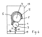
図4には、択一的な実施の形態が、図3の実施の形態に類似して示してある。図3と異なり、図4では、円筒歯車1,2が互いに重なり合って位置決めされている(図示の構成部材については、図3および対応する符号参照)。 In FIG. 4, an alternative embodiment is shown similar to the embodiment of FIG. Unlike FIG. 3, in FIG. 4, the cylindrical gears 1 and 2 are positioned so as to overlap each other (see FIG. 3 and the corresponding reference numerals for the components shown in the figure).
図4では、上側の円筒歯車、この実施の形態では第2の円筒歯車2が、3/4、すなわち、約270°にわたって包囲壁5によって取り囲まれており、下側の円筒歯車、この実施の形態では第1の円筒歯車1がその全周の1/4にわたって、すなわち、約90°にわたって包囲壁5によって取り囲まれている。したがって、第1の円筒歯車1のうちの下側半分が包囲壁5を越えて下方に突出している(図4でも、上方からの包囲壁5が終端している平面を示す破線を再度参照)。また、油溜め19もしくは伝動装置ハウジング13に対する下側の円筒歯車1の間隔d、Dも、図3に示した実施の形態と同様に、やはり、取囲みもしくは包込みの領域における円筒歯車1,2と包囲壁5との間の間隔の複数倍である。
In FIG. 4, the upper cylindrical gear, in this embodiment the second
図5には、本発明の1つの形態、つまり、円筒歯車1,2の冷却を円筒歯車1,2の潤滑から切り離す形態が示してある。したがって、円筒歯車1,2を冷却するための第1の油体積流が包囲壁5を通して案内される。第1の油体積流は符号21で示してある。この第1の油体積流21を圧送するために、第1の油ポンプ22が概略的に図示してある。この第1の油ポンプ22は油を油溜め19から圧送する。しかしながら、このことは必ずしも必要ではなく、別種の冷媒または別種の圧送が特定されていてもよい。付加的または択一的には、破線によって図示したように、包囲壁5が、第1の油体積流21の散布によって冷却されてもよい。
FIG. 5 shows one mode of the present invention, that is, a mode in which the cooling of the
円筒歯車1,2を潤滑するためには、第2の油体積流23が、円筒歯車1,2の歯列、有利には歯列の噛合い領域15に、図2に示したような、たとえば1つまたはそれ以上の開口12を通して案内される。第2の油体積流23は、たとえば第2の油ポンプ24によって油溜め19から圧送される。しかしながら、ここでも、別種の圧送または別種の供給源が考慮されてもよい。
In order to lubricate the cylindrical gears 1, 2, a second
第1の油体積流21と第2の油体積流23とは、1つの共通の油ポンプによって圧送されてもよい。しかしながら、いずれにせよ、有利には、第1の油体積流21が第2の油体積流23よりも多く、特に第2の油体積流23の複数倍の量である。
The first
第2の油体積流23が、有利には円筒歯車1,2から自由に落下することができるのに対して、第1の油体積流21は、通常、包囲壁5に設けられた少なくとも1つの相応の開口から流出するかまたは、包囲壁5への散布時には、この包囲壁5から流下するかもしくは滴下する。
The second
包囲壁5をアクティブに冷却することによって、円筒歯車1,2を、直接的な冷却と異なり、環状ギャップ6,7を介して包囲壁5への熱伝達によって間接的に冷却することができる。これによって、環状ギャップ6,7および/または歯列の噛合い領域15を通して比較的少ない潤滑油体積流、この実施の形態では第2の油体積流23を搬送することが可能となる。このことは、損失を減少させる。
By actively cooling the surrounding
さらに、図示の実施の形態では、外側で包囲壁5に設けられた複数の冷却フィン25による包囲壁5の冷却が概略的に示してある。
Further, in the illustrated embodiment, cooling of the surrounding
本発明の1つの実施の形態によれば、包囲壁5が少なくとも1つの冷却フィン25によってしか冷却されないにもかかわらず、歯列によってもしくは歯列に沿って、特に環状ギャップ6,7を通して案内される冷媒流、この実施の形態では第2の油体積流23よりも大きな熱流が包囲壁5を介して導出されれば十分であることも可能である。
According to one embodiment of the invention, the surrounding
Claims (15)
1.1 両方の前記円筒歯車(1,2)を周方向でかつ前記回転軸線(3,4)の方向で取り囲む包囲壁(5)を備え、
1.2 前記包囲壁(5)は、該包囲壁(5)と前記円筒歯車(1,2)との間に、互いに移行し合う2つの環状ギャップ(6,7)が形成されるように、前記円筒歯車(1,2)の外径に適合された内側輪郭を有し、それぞれ1つの前記環状ギャップ(6,7)は、前記それぞれ1つの回転軸線(3,4)に対して少なくともほぼ同心に配置されており、
1.3 前記包囲壁(5)は、前記両方の円筒歯車(1,2)を前記周方向でその全周の一部にわたってのみ取り囲んでおり、これによって、前記両方の円筒歯車(1,2)の外周の一部または前記両方の円筒歯車(1,2)のうちの少なくとも一方の円筒歯車の外周の一部が、前記包囲壁(5)を越えて外方に突出している、
円筒歯車伝動装置において、
前記両方の円筒歯車(1,2)または前記一方の円筒歯車(1,2)の、前記包囲壁(5)を越えて突出した前記一部は、前記円筒歯車(1,2)のうちの下側に位置決めされていることを特徴とする、円筒歯車伝動装置。 A cylindrical gear transmission comprising at least two cylindrical gears (1, 2) having tooth rows, wherein the tooth rows of the cylindrical gears (1, 2) are engaged in mesh with each other; The cylindrical gears (1, 2) can rotate around one rotation axis (3, 4),
1.1 comprising an enclosing wall (5) surrounding both said cylindrical gears (1, 2) in the circumferential direction and in the direction of said rotational axis (3, 4);
1.2 The surrounding wall (5) is formed such that two annular gaps (6, 7) are formed between the surrounding wall (5) and the cylindrical gears (1, 2). Each of the annular gaps (6, 7) at least with respect to the respective rotation axis (3, 4). Are located almost concentrically,
1.3 The surrounding wall (5) surrounds both the cylindrical gears (1, 2) in the circumferential direction only over a part of their entire circumference, whereby both the cylindrical gears (1, 2) ) Or a part of the outer periphery of at least one of the cylindrical gears (1, 2) protrudes outward beyond the surrounding wall (5),
In cylindrical gear transmission,
The part of the cylindrical gears (1, 2) or the one cylindrical gear (1, 2) protruding beyond the surrounding wall (5) A cylindrical gear transmission characterized by being positioned on the lower side.
Applications Claiming Priority (3)
| Application Number | Priority Date | Filing Date | Title |
|---|---|---|---|
| DE102014209922.6 | 2014-05-23 | ||
| DE102014209922 | 2014-05-23 | ||
| PCT/EP2015/061359 WO2015177332A1 (en) | 2014-05-23 | 2015-05-22 | Spur gear transmission |
Publications (2)
| Publication Number | Publication Date |
|---|---|
| JP2017516965A true JP2017516965A (en) | 2017-06-22 |
| JP6538827B2 JP6538827B2 (en) | 2019-07-03 |
Family
ID=53200007
Family Applications (1)
| Application Number | Title | Priority Date | Filing Date |
|---|---|---|---|
| JP2017513348A Active JP6538827B2 (en) | 2014-05-23 | 2015-05-22 | Cylindrical gear transmission |
Country Status (7)
| Country | Link |
|---|---|
| US (2) | US10378640B2 (en) |
| EP (2) | EP3146239B1 (en) |
| JP (1) | JP6538827B2 (en) |
| CN (1) | CN106415077B (en) |
| DE (1) | DE102015209403A1 (en) |
| ES (1) | ES2690472T3 (en) |
| WO (1) | WO2015177332A1 (en) |
Cited By (3)
| Publication number | Priority date | Publication date | Assignee | Title |
|---|---|---|---|---|
| JPWO2022270215A1 (en) * | 2021-06-24 | 2022-12-29 | ||
| JP2024508410A (en) * | 2021-02-11 | 2024-02-27 | フレンダー-グラフェンスタデン エス.アー.エス. | System to reduce tooth power loss in gearbox |
| JP2025117157A (en) * | 2024-01-30 | 2025-08-12 | 株式会社豊田中央研究所 | Gear lubrication device and gear lubrication method |
Families Citing this family (9)
| Publication number | Priority date | Publication date | Assignee | Title |
|---|---|---|---|---|
| DE102015221299A1 (en) | 2015-10-30 | 2017-05-04 | Voith Patent Gmbh | Spur gears |
| DE102015221234A1 (en) | 2015-10-30 | 2017-05-04 | Voith Patent Gmbh | Spur gears |
| DE102016209549A1 (en) * | 2016-06-01 | 2017-12-07 | Voith Patent Gmbh | Spur gears |
| DE102017207584A1 (en) * | 2017-05-05 | 2018-11-08 | Volkswagen Aktiengesellschaft | Motor vehicle transmission with integrated oil delivery unit |
| US11143286B2 (en) * | 2019-03-15 | 2021-10-12 | Hamilton Sundstrand Corporation | Differential unit gear shrouds |
| DE102021120100A1 (en) | 2021-08-03 | 2023-02-09 | Voith Patent Gmbh | spur gear |
| DE102021120098A1 (en) | 2021-08-03 | 2023-02-09 | Voith Patent Gmbh | spur gear |
| US12098764B2 (en) * | 2022-03-07 | 2024-09-24 | Hamilton Sundstrand Corporation | Shroud with integrated lube jets |
| US12025131B2 (en) * | 2022-08-08 | 2024-07-02 | Deere & Company | Torque transfer gear pump |
Citations (4)
| Publication number | Priority date | Publication date | Assignee | Title |
|---|---|---|---|---|
| US3489034A (en) * | 1968-05-17 | 1970-01-13 | Gen Electric | Evacuated gear casing |
| DE102006022964A1 (en) * | 2006-05-12 | 2007-11-22 | Getrag Getriebe- Und Zahnradfabrik Hermann Hagenmeyer Gmbh & Cie Kg | Fluid expansion tank and gearbox equipped therewith |
| DE102007041318A1 (en) * | 2007-08-31 | 2009-03-05 | GM Global Technology Operations, Inc., Detroit | Manual transmission with gear pump |
| US20130025405A1 (en) * | 2009-06-05 | 2013-01-31 | Kawasaki Jukogyo Kabushiki Kaisha | Gear train lubricating device |
Family Cites Families (17)
| Publication number | Priority date | Publication date | Assignee | Title |
|---|---|---|---|---|
| GB292540A (en) | 1927-06-21 | 1928-09-06 | Gen Electric | Improvements in or relating to lubricating devices for gear wheels |
| US2017871A (en) * | 1932-04-01 | 1935-10-22 | Hoe & Co R | Lubricant spreader for gears |
| GB458379A (en) | 1935-04-24 | 1936-12-18 | Charles Hern Oshei | Improvements in and relating to motor vehicles |
| US2214485A (en) * | 1939-03-23 | 1940-09-10 | Westinghouse Electric & Mfg Co | Gear lubrication apparatus |
| GB681298A (en) * | 1950-04-05 | 1952-10-22 | Tarpen Engineering Company Ltd | Improvements in or relating to gear cases for motor driven appliances |
| US2645305A (en) | 1951-05-22 | 1953-07-14 | Willys Motors Inc | Means for lubricating bearings |
| US3601515A (en) * | 1969-07-30 | 1971-08-24 | Mack Trucks | Lubricant pump |
| GB1426352A (en) | 1973-02-09 | 1976-02-25 | Holmes Co Ltd W C | Gear lubrication device |
| US4778000A (en) * | 1986-12-31 | 1988-10-18 | Reliance Electric Company | Cooling system |
| US5048370A (en) * | 1989-10-18 | 1991-09-17 | Bell Helicopter Textron Inc. | Gear shrouding system |
| CH688630A5 (en) | 1994-11-14 | 1997-12-15 | Maag Getriebe Ag | Gear transmission. |
| DE19860353C1 (en) | 1998-12-28 | 2000-06-21 | Renk Ag | transmission |
| JP5141699B2 (en) | 2010-02-04 | 2013-02-13 | トヨタ自動車株式会社 | Lubricating oil supply device |
| CA2789417C (en) | 2010-02-10 | 2015-08-04 | Kawasaki Jukogyo Kabushiki Kaisha | Gear train lubricating device |
| DE102010036141A1 (en) | 2010-09-02 | 2012-03-08 | Voith Patent Gmbh | gear transmission |
| EP2700849B1 (en) | 2011-04-20 | 2016-05-11 | Toyota Jidosha Kabushiki Kaisha | Lubricating oil supply device for power transmission device |
| US9227225B2 (en) * | 2013-03-01 | 2016-01-05 | American Piledriving Equipment, Inc. | Bearing cooling system for vibratory devices |
-
2015
- 2015-05-22 WO PCT/EP2015/061359 patent/WO2015177332A1/en not_active Ceased
- 2015-05-22 ES ES15723969.0T patent/ES2690472T3/en active Active
- 2015-05-22 EP EP15723969.0A patent/EP3146239B1/en active Active
- 2015-05-22 CN CN201580032845.1A patent/CN106415077B/en active Active
- 2015-05-22 US US15/312,890 patent/US10378640B2/en active Active
- 2015-05-22 EP EP18177468.8A patent/EP3406944A1/en not_active Withdrawn
- 2015-05-22 DE DE102015209403.0A patent/DE102015209403A1/en active Pending
- 2015-05-22 JP JP2017513348A patent/JP6538827B2/en active Active
-
2019
- 2019-02-22 US US16/283,104 patent/US10760671B2/en active Active
Patent Citations (4)
| Publication number | Priority date | Publication date | Assignee | Title |
|---|---|---|---|---|
| US3489034A (en) * | 1968-05-17 | 1970-01-13 | Gen Electric | Evacuated gear casing |
| DE102006022964A1 (en) * | 2006-05-12 | 2007-11-22 | Getrag Getriebe- Und Zahnradfabrik Hermann Hagenmeyer Gmbh & Cie Kg | Fluid expansion tank and gearbox equipped therewith |
| DE102007041318A1 (en) * | 2007-08-31 | 2009-03-05 | GM Global Technology Operations, Inc., Detroit | Manual transmission with gear pump |
| US20130025405A1 (en) * | 2009-06-05 | 2013-01-31 | Kawasaki Jukogyo Kabushiki Kaisha | Gear train lubricating device |
Cited By (6)
| Publication number | Priority date | Publication date | Assignee | Title |
|---|---|---|---|---|
| JP2024508410A (en) * | 2021-02-11 | 2024-02-27 | フレンダー-グラフェンスタデン エス.アー.エス. | System to reduce tooth power loss in gearbox |
| JP7629109B2 (en) | 2021-02-11 | 2025-02-12 | フレンダー-グラフェンスタデン エス.アー.エス. | System for reducing tooth power losses in gearboxes |
| US12442444B2 (en) | 2021-02-11 | 2025-10-14 | Flender-Graffenstaden S.A.S. | System for reducing teeth power losses in a gearbox |
| JPWO2022270215A1 (en) * | 2021-06-24 | 2022-12-29 | ||
| JP7547023B2 (en) | 2021-06-24 | 2024-09-09 | ジヤトコ株式会社 | vehicle |
| JP2025117157A (en) * | 2024-01-30 | 2025-08-12 | 株式会社豊田中央研究所 | Gear lubrication device and gear lubrication method |
Also Published As
| Publication number | Publication date |
|---|---|
| US20170184193A1 (en) | 2017-06-29 |
| CN106415077A (en) | 2017-02-15 |
| JP6538827B2 (en) | 2019-07-03 |
| EP3406944A1 (en) | 2018-11-28 |
| ES2690472T3 (en) | 2018-11-21 |
| CN106415077B (en) | 2019-03-12 |
| DE102015209403A1 (en) | 2015-11-26 |
| EP3146239B1 (en) | 2018-07-25 |
| EP3146239A1 (en) | 2017-03-29 |
| US10378640B2 (en) | 2019-08-13 |
| US10760671B2 (en) | 2020-09-01 |
| US20190195335A1 (en) | 2019-06-27 |
| WO2015177332A1 (en) | 2015-11-26 |
Similar Documents
| Publication | Publication Date | Title |
|---|---|---|
| JP2017516965A (en) | Cylindrical gear transmission | |
| JP6743140B2 (en) | Cylindrical gear transmission mechanism | |
| JP6873123B2 (en) | Cylindrical gear transmission mechanism | |
| JP2019521291A (en) | Cylindrical gear transmission mechanism | |
| CN106460667B (en) | It include the turbogenerator module around the shell of the equipment with the lid for recycling lubricating oil | |
| US9309959B2 (en) | Power transmission device | |
| JPH0410396Y2 (en) | ||
| JP6088212B2 (en) | Screw compressor | |
| JP5763358B2 (en) | Vacuum pump | |
| CN105276131A (en) | Speed reduction drive device with damping, lubricating, cooling and air pressure balancing functions | |
| JP2006518827A (en) | Rotary piston pump | |
| US10590928B2 (en) | Gear pump that removes air from pumped oil | |
| CN111924461A (en) | Synchronous double-eccentric-shaft vibration excitation device and thin oil lubrication method | |
| JP6044824B2 (en) | Internal gear pump | |
| JPH0299790A (en) | Multistage vacuum pump | |
| KR101065288B1 (en) | Cooled Vacuum Pump | |
| JP7004175B2 (en) | Electric supercharger | |
| ES2474565T3 (en) | Breathing and lubrication device for a closed mechanical system | |
| KR20140004906U (en) | Gear pump having enhanced lubricating ability | |
| JP6238872B2 (en) | Liquid-cooled screw compressor | |
| JP2023079785A (en) | Structure for recovering leaked oil from screw compressors | |
| CN105349721B (en) | Semi-closed type water cooling device adopting unidirectional slewing mechanism for distributor | |
| JP2015218835A (en) | Industrial drive | |
| JP2022084338A (en) | Leaked oil recovery structure in shaft seal portion of screw compressor | |
| TWM491733U (en) | Oil seal assembly structure for submersible pump |
Legal Events
| Date | Code | Title | Description |
|---|---|---|---|
| A621 | Written request for application examination |
Free format text: JAPANESE INTERMEDIATE CODE: A621 Effective date: 20180130 |
|
| A977 | Report on retrieval |
Free format text: JAPANESE INTERMEDIATE CODE: A971007 Effective date: 20190116 |
|
| A131 | Notification of reasons for refusal |
Free format text: JAPANESE INTERMEDIATE CODE: A131 Effective date: 20190128 |
|
| A521 | Request for written amendment filed |
Free format text: JAPANESE INTERMEDIATE CODE: A523 Effective date: 20190418 |
|
| TRDD | Decision of grant or rejection written | ||
| A01 | Written decision to grant a patent or to grant a registration (utility model) |
Free format text: JAPANESE INTERMEDIATE CODE: A01 Effective date: 20190508 |
|
| A61 | First payment of annual fees (during grant procedure) |
Free format text: JAPANESE INTERMEDIATE CODE: A61 Effective date: 20190606 |
|
| R150 | Certificate of patent or registration of utility model |
Ref document number: 6538827 Country of ref document: JP Free format text: JAPANESE INTERMEDIATE CODE: R150 |
|
| R250 | Receipt of annual fees |
Free format text: JAPANESE INTERMEDIATE CODE: R250 |
|
| R250 | Receipt of annual fees |
Free format text: JAPANESE INTERMEDIATE CODE: R250 |
|
| R250 | Receipt of annual fees |
Free format text: JAPANESE INTERMEDIATE CODE: R250 |
|
| R250 | Receipt of annual fees |
Free format text: JAPANESE INTERMEDIATE CODE: R250 |