JP2017531419A - 回転電気機械のためのロータ本体 - Google Patents
回転電気機械のためのロータ本体 Download PDFInfo
- Publication number
- JP2017531419A JP2017531419A JP2017520425A JP2017520425A JP2017531419A JP 2017531419 A JP2017531419 A JP 2017531419A JP 2017520425 A JP2017520425 A JP 2017520425A JP 2017520425 A JP2017520425 A JP 2017520425A JP 2017531419 A JP2017531419 A JP 2017531419A
- Authority
- JP
- Japan
- Prior art keywords
- rotor
- rotor body
- groove
- section
- axial
- Prior art date
- Legal status (The legal status is an assumption and is not a legal conclusion. Google has not performed a legal analysis and makes no representation as to the accuracy of the status listed.)
- Pending
Links
Images
Classifications
-
- H—ELECTRICITY
- H02—GENERATION; CONVERSION OR DISTRIBUTION OF ELECTRIC POWER
- H02K—DYNAMO-ELECTRIC MACHINES
- H02K1/00—Details of the magnetic circuit
- H02K1/06—Details of the magnetic circuit characterised by the shape, form or construction
- H02K1/22—Rotating parts of the magnetic circuit
- H02K1/32—Rotating parts of the magnetic circuit with channels or ducts for flow of cooling medium
-
- H—ELECTRICITY
- H02—GENERATION; CONVERSION OR DISTRIBUTION OF ELECTRIC POWER
- H02K—DYNAMO-ELECTRIC MACHINES
- H02K3/00—Details of windings
- H02K3/04—Windings characterised by the conductor shape, form or construction, e.g. with bar conductors
- H02K3/24—Windings characterised by the conductor shape, form or construction, e.g. with bar conductors with channels or ducts for cooling medium between the conductors
Landscapes
- Engineering & Computer Science (AREA)
- Power Engineering (AREA)
- Insulation, Fastening Of Motor, Generator Windings (AREA)
- Motor Or Generator Cooling System (AREA)
- Windings For Motors And Generators (AREA)
- Iron Core Of Rotating Electric Machines (AREA)
Abstract
Description
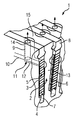
2 ロータ歯
3 位置決めスロット
4 導体要素
5 導体区間
6 電気絶縁体
7 スロット基礎通路
8 スロット楔
9 径方向の孔
10 軸方向の冷却通路
11 溝
12 軸方向の溝区間
13 端面
14 径方向の溝区間
15 外殻表面
Claims (6)
- 回転電気機械のロータのためのロータ本体(1)であって、
周方向に分配されるように配置された、軸方向に延びる複数のロータ歯(2)を有し、それらの間に前記ロータのロータ巻線の導体区間(5)を各々の場合に収容するための軸方向に延びる位置決めスロット(3)が配置され、少なくとも1つの溝(11)が、少なくとも1つのロータ歯(2)の少なくとも1つの径方向の側壁に配置され、前記溝は、前記ロータ本体(1)の端面(13)から前記ロータ本体(1)の所定の小区間にわたって少なくとも部分的に軸方向に延びる少なくとも1つの溝区間(12)を有し、且つ
前記溝は、前記軸方向の溝区間(12)に連通するように連結されて前記軸方向の溝区間(12)から前記ロータ本体(1)の外殻表面(15)に向かって少なくとも部分的に径方向に延びる少なくとも1つの径方向の溝区間(14)を有するロータ本体(1)。 - 前記ロータ本体(1)の前記所定の小区間は、前記ロータ本体(1)の軸方向の長さの半分より設計上短い、請求項1に記載のロータ本体(1)。
- 前記溝(11)は、前記ロータ歯(2)の前記径方向の側壁の半分の位置で、径方向外側の壁に配置される、請求項1または2に記載のロータ本体(1)。
- 前記溝(11)は、少なくとも部分的に、断面において円形の断片状のデザインのものである、請求項1から3のいずれか一項に記載のロータ本体(1)。
- 少なくとも1つの溝区間(12、14)が直線的に延びる、請求項1から4のいずれか一項に記載のロータ本体(1)。
- ステータと、少なくとも1つのロータ本体(1)を伴うロータとを有し、
前記ロータ本体(1)は、請求項1から5のいずれか一項に記載されるように設計される、特にタービン発電機である、回転電気機械。
Applications Claiming Priority (3)
| Application Number | Priority Date | Filing Date | Title |
|---|---|---|---|
| EP14188949.3 | 2014-10-15 | ||
| EP14188949.3A EP3010117A1 (de) | 2014-10-15 | 2014-10-15 | Rotorballen für eine rotierende elektrische Maschine |
| PCT/EP2015/072903 WO2016058854A1 (de) | 2014-10-15 | 2015-10-05 | Rotorballen für eine rotierende elektrische maschine |
Publications (1)
| Publication Number | Publication Date |
|---|---|
| JP2017531419A true JP2017531419A (ja) | 2017-10-19 |
Family
ID=51730384
Family Applications (1)
| Application Number | Title | Priority Date | Filing Date |
|---|---|---|---|
| JP2017520425A Pending JP2017531419A (ja) | 2014-10-15 | 2015-10-05 | 回転電気機械のためのロータ本体 |
Country Status (5)
| Country | Link |
|---|---|
| US (1) | US20170310178A1 (ja) |
| EP (2) | EP3010117A1 (ja) |
| JP (1) | JP2017531419A (ja) |
| CN (1) | CN107078576A (ja) |
| WO (1) | WO2016058854A1 (ja) |
Families Citing this family (2)
| Publication number | Priority date | Publication date | Assignee | Title |
|---|---|---|---|---|
| CN111786487A (zh) * | 2020-08-05 | 2020-10-16 | 广州广重企业集团有限公司 | 一种电机转子冷却槽结构 |
| CN111786486A (zh) * | 2020-08-05 | 2020-10-16 | 广州广重企业集团有限公司 | 一种电机转子内冷结构 |
Citations (5)
| Publication number | Priority date | Publication date | Assignee | Title |
|---|---|---|---|---|
| JPS5143304U (ja) * | 1974-09-26 | 1976-03-31 | ||
| JPS58145056U (ja) * | 1982-03-23 | 1983-09-29 | 株式会社日立製作所 | 回転電機の回転子 |
| JPS599741U (ja) * | 1982-07-07 | 1984-01-21 | 三菱電機株式会社 | 回転電機の回転子鉄心 |
| JPS6158837U (ja) * | 1984-09-18 | 1986-04-21 | ||
| JPH0951644A (ja) * | 1995-08-04 | 1997-02-18 | Hitachi Ltd | 回転電機の回転子 |
Family Cites Families (6)
| Publication number | Priority date | Publication date | Assignee | Title |
|---|---|---|---|---|
| JPS54139004A (en) * | 1978-04-19 | 1979-10-29 | Hitachi Ltd | Air wedge for rotor of rotary machine |
| JPS56139335U (ja) * | 1980-03-22 | 1981-10-21 | ||
| US5329197A (en) * | 1992-10-29 | 1994-07-12 | General Electric Company | Generator rotor winding with two coils per slot |
| JP2001086679A (ja) * | 1999-09-17 | 2001-03-30 | Hitachi Ltd | 回転電機 |
| US6844637B1 (en) * | 2003-08-13 | 2005-01-18 | Curtiss-Wright Electro-Mechanical Corporation | Rotor assembly end turn cooling system and method |
| US9647505B2 (en) * | 2012-12-19 | 2017-05-09 | Mitsubishi Electric Corporation | Rotating electrical machine |
-
2014
- 2014-10-15 EP EP14188949.3A patent/EP3010117A1/de not_active Withdrawn
-
2015
- 2015-10-05 EP EP15774919.3A patent/EP3180837A1/de not_active Withdrawn
- 2015-10-05 CN CN201580056279.8A patent/CN107078576A/zh active Pending
- 2015-10-05 JP JP2017520425A patent/JP2017531419A/ja active Pending
- 2015-10-05 US US15/517,304 patent/US20170310178A1/en not_active Abandoned
- 2015-10-05 WO PCT/EP2015/072903 patent/WO2016058854A1/de not_active Ceased
Patent Citations (5)
| Publication number | Priority date | Publication date | Assignee | Title |
|---|---|---|---|---|
| JPS5143304U (ja) * | 1974-09-26 | 1976-03-31 | ||
| JPS58145056U (ja) * | 1982-03-23 | 1983-09-29 | 株式会社日立製作所 | 回転電機の回転子 |
| JPS599741U (ja) * | 1982-07-07 | 1984-01-21 | 三菱電機株式会社 | 回転電機の回転子鉄心 |
| JPS6158837U (ja) * | 1984-09-18 | 1986-04-21 | ||
| JPH0951644A (ja) * | 1995-08-04 | 1997-02-18 | Hitachi Ltd | 回転電機の回転子 |
Also Published As
| Publication number | Publication date |
|---|---|
| CN107078576A (zh) | 2017-08-18 |
| EP3010117A1 (de) | 2016-04-20 |
| EP3180837A1 (de) | 2017-06-21 |
| US20170310178A1 (en) | 2017-10-26 |
| WO2016058854A1 (de) | 2016-04-21 |
Similar Documents
| Publication | Publication Date | Title |
|---|---|---|
| US10320247B2 (en) | Embedded permanent magnet rotary electric machine | |
| KR101757285B1 (ko) | 전기 기계를 위한 회전하는 지향성 냉각재 스프레이 | |
| JP6526647B2 (ja) | 回転電機 | |
| CN102447342B (zh) | 旋转电机的壳体 | |
| JP6226938B2 (ja) | 回転電機 | |
| WO2017082023A1 (ja) | 回転電機 | |
| US8975792B2 (en) | Electric machine module cooling system and method | |
| US20160020673A1 (en) | Rotor cooling | |
| KR20170004860A (ko) | 모터의 냉각 구조 | |
| KR101792915B1 (ko) | 고정자 코일 직접 냉각방식형 모터 | |
| KR20120041760A (ko) | 회전 전기 기계를 위한 컬렉터 링 배열체 | |
| JP2015012792A (ja) | 回転電機のステータ | |
| KR20100117040A (ko) | 열전달이 증대된 발전전동기계 로터 및 그것을 제조하는 방법 | |
| JP2015208138A (ja) | 車両用回転電機 | |
| US20170310178A1 (en) | Rotor body for a rotating electrical machine | |
| JP2010029060A (ja) | ダイナモ発電機械ロータ用の通気煙突の伝熱促進 | |
| KR102600355B1 (ko) | 전기 기계를 위한 슬립 링 배열체 | |
| JP6453091B2 (ja) | 回転電機 | |
| JP2022516268A5 (ja) | ||
| JP6488250B2 (ja) | 回転電機のステータ | |
| JP6102003B2 (ja) | ロータアセンブリ | |
| KR101834338B1 (ko) | 유도전동기 | |
| JP6907609B2 (ja) | 回転電機 | |
| KR20160122827A (ko) | 회전식 전기 기계의 로터 | |
| JP6833543B2 (ja) | 回転電機 |
Legal Events
| Date | Code | Title | Description |
|---|---|---|---|
| A521 | Request for written amendment filed |
Free format text: JAPANESE INTERMEDIATE CODE: A523 Effective date: 20170712 |
|
| A621 | Written request for application examination |
Free format text: JAPANESE INTERMEDIATE CODE: A621 Effective date: 20170712 |
|
| A131 | Notification of reasons for refusal |
Free format text: JAPANESE INTERMEDIATE CODE: A131 Effective date: 20180625 |
|
| A601 | Written request for extension of time |
Free format text: JAPANESE INTERMEDIATE CODE: A601 Effective date: 20180925 |
|
| A02 | Decision of refusal |
Free format text: JAPANESE INTERMEDIATE CODE: A02 Effective date: 20190304 |