JP2017532097A - Seat assist device - Google Patents
Seat assist device Download PDFInfo
- Publication number
- JP2017532097A JP2017532097A JP2017512994A JP2017512994A JP2017532097A JP 2017532097 A JP2017532097 A JP 2017532097A JP 2017512994 A JP2017512994 A JP 2017512994A JP 2017512994 A JP2017512994 A JP 2017512994A JP 2017532097 A JP2017532097 A JP 2017532097A
- Authority
- JP
- Japan
- Prior art keywords
- lift
- seat
- slide
- lift arm
- lift platform
- Prior art date
- Legal status (The legal status is an assumption and is not a legal conclusion. Google has not performed a legal analysis and makes no representation as to the accuracy of the status listed.)
- Pending
Links
- MOZWYIQTRYIZJO-UHFFFAOYSA-N CC1=C=CC=CC1 Chemical compound CC1=C=CC=CC1 MOZWYIQTRYIZJO-UHFFFAOYSA-N 0.000 description 1
Images









Classifications
-
- A—HUMAN NECESSITIES
- A61—MEDICAL OR VETERINARY SCIENCE; HYGIENE
- A61G—TRANSPORT, PERSONAL CONVEYANCES, OR ACCOMMODATION SPECIALLY ADAPTED FOR PATIENTS OR DISABLED PERSONS; OPERATING TABLES OR CHAIRS; CHAIRS FOR DENTISTRY; FUNERAL DEVICES
- A61G5/00—Chairs or personal conveyances specially adapted for patients or disabled persons, e.g. wheelchairs
- A61G5/10—Parts, details or accessories
- A61G5/14—Standing-up or sitting-down aids
-
- A—HUMAN NECESSITIES
- A47—FURNITURE; DOMESTIC ARTICLES OR APPLIANCES; COFFEE MILLS; SPICE MILLS; SUCTION CLEANERS IN GENERAL
- A47K—SANITARY EQUIPMENT; ACCESSORIES THEREFOR, e.g. TOILET ACCESSORIES
- A47K13/00—Seats or covers for all kinds of closets
- A47K13/10—Devices for raising and lowering ; Collapsible or rotating seats or covers
- A47K13/105—Toilet seat or toilet cover handles
Landscapes
- Health & Medical Sciences (AREA)
- Public Health (AREA)
- Life Sciences & Earth Sciences (AREA)
- Animal Behavior & Ethology (AREA)
- General Health & Medical Sciences (AREA)
- Veterinary Medicine (AREA)
- Special Chairs (AREA)
- Chair Legs, Seat Parts, And Backrests (AREA)
- Non-Flushing Toilets (AREA)
- Toilet Supplies (AREA)
Abstract
シート補助装置が記載されている。シート補助装置は、土台(102)、前部(109)と後部(107)を有するリフトプラットフォーム(104)を備え、リフトプラットフォーム(104)の前部(109)が土台(102)に枢動自在に接続されている(1714)。リフトアーム(106)はリフトプラットフォーム(104)の後部(107)に接続される。リフトアーム(106)はリフトプラットフォーム(104)の前部を越えて突出するようにリフトプラットフォーム(104)から伸び、リフトアーム(106)はユーザー(802)によって把持されるハンドル(112)で終了する。リフトバー(108)は土台(102)とリフトアーム(106)との間で枢動自在に接続され、それによって、シート補助装置に座っているユーザー(802)は、ハンドル(112)を押し下げる(114)ことでリフトプラットフォーム(104)の後部(107)を上昇させることができ、その際にユーザー(802)が着座位置から立ち上がるのを補助することができる。【選択図】図1A seat auxiliary device is described. The seat auxiliary device includes a base (102), a lift platform (104) having a front part (109) and a rear part (107), and the front part (109) of the lift platform (104) is pivotable to the base (102). (1714). The lift arm (106) is connected to the rear (107) of the lift platform (104). The lift arm (106) extends from the lift platform (104) so as to protrude beyond the front of the lift platform (104), and the lift arm (106) terminates with a handle (112) gripped by the user (802). . The lift bar (108) is pivotally connected between the base (102) and the lift arm (106) so that the user (802) sitting on the seat assist device pushes down the handle (112) (114). ) To raise the rear part (107) of the lift platform (104), and at this time, it is possible to assist the user (802) to stand up from the seating position. [Selection] Figure 1
Description
本発明はポータブルシート補助装置に関し、具体的には、ユーザーを着座位置へ下げたり着座位置から上げたりする際にユーザーを補助するために、多種多様な家具と共に使用することができるポータブル装置に関する。 The present invention relates to portable seat assistance devices, and more particularly to portable devices that can be used with a wide variety of furniture to assist the user in lowering or raising the user from the seated position.
シート補助装置は当該技術分野で知られており、障害のある人、太り過ぎの人、および高齢者が着座位置に座ったり着座位置から立ち上がったりするのを補助するために使用されるのが一般的である。 Seat assist devices are known in the art and are typically used to assist people with disabilities, overweight people, and the elderly in sitting or getting up from the sitting position. It is.
上記のようなシート補助装置は、持ち上げ機能を提供する専用の家具として設計されることが多い。例えば、電動式のクッション付きの椅子は、所望のシート補助動作をユーザーに与える一方で、快適な家具も提供する。こうした電動式のクッション付きの椅子は一般に、電動式のリフトアクチュエータおよびはさみ機構によって作動する。操作の間、アクチュエーターおよびはさみ機構は、椅子全体を持ち上げて傾け、それによって、ユーザーが容易に着座位置に座ったり着座位置から立ち上がったりることを可能にする。こうした専用の家具に関する問題は、それが巨大で、高価で、家具の1つのピースに組み入れられるほど携帯式ではないことである。 Such seat auxiliary devices are often designed as dedicated furniture that provides a lifting function. For example, a motorized cushioned chair provides the user with the desired seat assistance movement while also providing comfortable furniture. Such electric cushioned chairs are generally operated by an electric lift actuator and scissor mechanism. During operation, the actuator and scissor mechanism lifts and tilts the entire chair, thereby allowing the user to easily sit in and get up from the sitting position. The problem with such dedicated furniture is that it is huge, expensive and not portable enough to be integrated into one piece of furniture.
コストと携帯性の必要性に対処するために、携帯用で、かつ多種多様な家具に使用可能な少数の装置が考え出された。こうしたポータブル装置は小型で携帯可能である一方で、電動式であるか、またはばねなどの受動エネルギー保存機構を用いる。電動式のオプションは電気と複数の電源を必要とし、その電動式の機構のせいで比較的高価であり、破損しやすい追加部品を備えている。代替的に、ばねにより補助されるシート装置は、乗員の体重にばね力を一致させるための調整を必要とし、この場合もやはり、複数の信頼性の低い部品を有している。 To address the need for cost and portability, a few devices have been devised that are portable and can be used for a wide variety of furniture. While such portable devices are small and portable, they are motorized or use passive energy storage mechanisms such as springs. The motorized option requires electricity and multiple power supplies, is relatively expensive due to its motorized mechanism, and has additional components that are easily damaged. Alternatively, the spring-assisted seat device requires adjustment to match the spring force to the occupant's weight and again has a plurality of unreliable parts.
したがって、複数の代替的な電源に対立するものとして、ユーザーが自分の体重のみに基づいて座ったり立ったりする際に補助する能力を与えるシート補助装置に対するニーズが継続的に存在している。 Thus, as opposed to multiple alternative power sources, there is a continuing need for seat assistance devices that provide the ability for a user to assist in sitting and standing based solely on their weight.
本発明はシート補助装置を対象としている。シート補助装置は、土台、前部と後部を有するリフトプラットフォームを備え、リフトプラットフォームの前部は土台に枢動自在に接続される。リフトアームは、リフトプラットフォームの後部に接続される。リフトアームは、リフトプラットフォームの前部を越えて突出するようにリフトプラットフォームから伸び、リフトアームはユーザーによって把持されるハンドルで終了する。リフトバーは、土台とリフトアームとの間で枢動自在に接続され、それによって、シート補助装置に座っているユーザーがハンドルを押し下げることでリフトプラットフォームの後部を上昇させ、そうする際にユーザーが着座位置から立ち上がるのを補助する。 The present invention is directed to a seat auxiliary device. The seat auxiliary device includes a base, a lift platform having a front part and a rear part, and the front part of the lift platform is pivotally connected to the base. The lift arm is connected to the rear of the lift platform. The lift arm extends from the lift platform to protrude beyond the front of the lift platform, and the lift arm ends with a handle that is gripped by the user. The lift bar is pivotally connected between the base and the lift arm so that the user sitting on the seat assist device raises the rear of the lift platform by pushing down on the handle, and the user sits in doing so Assist in getting up from position.
別の態様では、シート補助装置は、リフトアームに摺動自在に接続されるスライドを備え、リフトバーはスライドに枢動自在に接続され、それによってリフトバーをリフトアームに枢動自在に接続する。 In another aspect, the seat assist device comprises a slide slidably connected to the lift arm, the lift bar being pivotally connected to the slide, thereby pivotally connecting the lift bar to the lift arm.
また別の態様では、シート補助装置は、土台とリフトアームにおよびその間で接続される制限ストラップを備え、制限ストラップはリフトプラットフォームの後部の上方への動きを制限するように動作可能である。 In yet another aspect, the seat assistance device includes a restriction strap connected to and between the base and the lift arm, the restriction strap being operable to restrict upward movement of the rear portion of the lift platform.
別の態様では、シート補助装置は、土台に取り付けられたピンチガードを備え、ピンチガードは、リフトプラットフォームと土台の間で指をはさまれないようにするために、リフトバーに近接して配される。 In another aspect, the seat assistance device comprises a pinch guard attached to the base, the pinch guard being placed in close proximity to the lift bar to prevent fingers from being pinched between the lift platform and the base. The
別の態様では、シート補助装置は、リフトアームに取り付けられた滑り止めを備え、滑り止めはスライドの前方への動きを防ぐためのリフトアーム上の突起である。 In another aspect, the seat assist device comprises a non-slip attached to the lift arm, the non-slip being a protrusion on the lift arm to prevent the slide from moving forward.
加えて、スライドは、スライドがリフトアームに沿って後方に摺動された折り畳み位置と、ユーザーがハンドルを上げる際にスライドが前方に引っ張られる待機位置との間で摺動可能である。 In addition, the slide is slidable between a folded position where the slide is slid rearward along the lift arm and a standby position where the slide is pulled forward as the user raises the handle.
別の態様では、シート補助装置は、リフトアームに取り付けられるスライドロックを備え、スライドロックはリフトアームに対して適所にスライドを選択的にロックするために形成される。 In another aspect, the seat assistance device comprises a slide lock attached to the lift arm, the slide lock being formed to selectively lock the slide in place relative to the lift arm.
さらに、リフトアームは、P−ストラップヒンジによってリフトプラットフォームの後部に枢動自在に接続される。 Furthermore, the lift arm is pivotally connected to the rear of the lift platform by a P-strap hinge.
また別の態様では、リフトプラットフォームは便座として形作られる。 In another aspect, the lift platform is shaped as a toilet seat.
別の態様では、土台は、リフトプラットフォームを上昇させ、便器の上にリフトプラットフォームを位置決めするために形成されたフレーム部材をさらに備える。 In another aspect, the foundation further comprises a frame member configured to raise the lift platform and position the lift platform over the toilet bowl.
最後に、当業者に理解できるように、本発明は本明細書に記載される本発明を形成および使用するための方法をさらに含む。 Finally, as will be appreciated by those skilled in the art, the present invention further includes methods for making and using the invention described herein.
本発明の目的、特徴、および利点は、以下の図面を参照するとともに本発明の様々な態様の以下の詳細な記載から明らかとなる。
本発明は、ポータブルシート補助装置に関し、より具体的には、ユーザーが着座位置へ座る及び着座位置から立ち上がるのを助けるための多種多様な家具とともに使用することができるポータブル装置に関する。以下の説明は、当業者が本発明を作成し使用することができる、および特定用途との関連でそれを組み込むことができるように提示されている。様々な修正が、異なる適用における様々な使用と同様に、当業者に容易に明白となり、本明細書で定義される一般的な原則が広範囲の実施形態に適用され得る。したがって、本発明は、提示される実施形態を限定するようには意図されていないが、本明細書に開示される原則および新規な特徴と一致する最も広い範囲と合致される。 The present invention relates to portable seat assistance devices and, more particularly, to portable devices that can be used with a wide variety of furniture to help a user sit and get up from a sitting position. The following description is presented to enable any person skilled in the art to make and use the invention, and to incorporate it in the context of a particular application. Various modifications will be readily apparent to those skilled in the art, as well as various uses in different applications, and the general principles defined herein may be applied to a wide range of embodiments. Accordingly, the present invention is not intended to limit the embodiments presented, but is to be accorded the widest scope consistent with the principles and novel features disclosed herein.
以下の詳細な説明では、本発明についてのより徹底的な理解を提供するために、多くの具体的な詳細が明記される。しかしながら、本発明がこれらの具体的な詳細に必ずしも限定されることなく実施され得ることが当業者に明白となる。他の実例では、本発明を不明瞭にしないようにするために、周知の構造および装置は、詳細にではなく、むしろブロック図形態で示される。 In the following detailed description, numerous specific details are set forth in order to provide a more thorough understanding of the present invention. However, it will be apparent to those skilled in the art that the present invention may be practiced without necessarily being limited to these specific details. In other instances, well-known structures and devices are shown in block diagram form, rather than in detail, in order to avoid obscuring the present invention.
読者の注意は、本明細書とともに出願され、本明細書とともに一般閲覧で公開されている、すべての論文および文書に向けられており、すべてのそのような論文および文書の内容は、引用によって本明細書に組み込まれる。(付随する請求項、要約書、および図面を含む)本明細書に開示される特徴はすべて、他に明確に指定されない限り、同じ、同等、または類似した目的を果たす代替特徴と置き換えられてもよい。したがって、他に明確に指定されない限り、開示される各特徴は、一般的な一連の同等または類似した特徴の一例にすぎない。 The reader's notice is directed to all papers and documents that have been filed with this specification and published for general viewing with this specification, and the contents of all such papers and documents are hereby incorporated by reference. Incorporated in the description. All features disclosed in this specification (including the appended claims, abstract, and drawings) may be replaced with alternative features serving the same, equivalent, or similar purpose, unless explicitly stated otherwise. Good. Thus, unless expressly specified otherwise, each feature disclosed is one example only of a generic series of equivalent or similar features.
さらに、指定された機能を実行する「ための手段」、または具体的な機能を実行する「ための工程」を明確に明記していない請求項における要素は、35 U.S.C. Section 112, Paragraph 6で指定されるような「手段」または「工程」句として解釈されないものとする。特に、本出願の請求項における「の工程」または「の作用」の使用は、35 U.S.C. Section 112, Paragraph 6の規定を行使するようには意図されていない。
Further, an element in a claim that does not explicitly specify “means for performing a specified function” or “step for performing” a specific function is 35 U.S. Pat. S. C. It shall not be interpreted as a “means” or “process” phrase as specified in
もし使用される場合、ラベルが、左、右、前、後ろ、上、下、前方、後方、時計回り、反時計回り、また左回りに、便宜上の目的のみで使用され、特定の一定方向を含蓄するようには意図されていないことに留意されたい。代わりに、それらは、対象の様々な部分間の相対的な位置及び/又は方向を反映するために使用される。 If used, the label is used for convenience purposes only in the left, right, front, back, top, bottom, front, back, clockwise, counterclockwise, and counterclockwise direction, and in a certain fixed direction. Note that it is not intended to be implied. Instead, they are used to reflect the relative position and / or orientation between the various parts of the object.
(1)記述
ユーザーが着座位置へ座る及び着座位置から立ち上がるのを助けるための広範囲の家具とともに使用することができるシート補助装置が記載されている。先行技術と対比させるために、本明細書に記載されるシート補助装置は、ユーザーを昇降させる上げるために、動力またはばねで駆動する機構を使用していない。代わりに、また読者に明白となるように、シート補助装置は、ユーザー自身の体重を利用して、下降操作および上昇操作を制御する。図1に示されるように、シート補助装置(100)は、土台(102)に枢動自在に接続されたリフトプラットフォーム(例えば、シート)(104)を備えた土台(102)を含む。例えば、リフトプラットフォーム(104)を土台(102)に枢動自在に接続するために、連続ヒンジまたは他の適切なヒンジ装置を使用することができる。
(1) Description A seat assistance device is described that can be used with a wide range of furniture to help a user sit and get up from a sitting position. In contrast to the prior art, the seat assistance device described herein does not use a power or spring driven mechanism to raise or lower the user. Instead, and as will be apparent to the reader, the seat assistance device uses the user's own weight to control the lowering and lifting operations. As shown in FIG. 1, the seat assist device (100) includes a base (102) with a lift platform (eg, seat) (104) pivotally connected to the base (102). For example, a continuous hinge or other suitable hinge device can be used to pivotally connect the lift platform (104) to the base (102).
土台(102)は、リフトプラットフォーム(104)が枢動することができる安定した土台を提供する、安定した機構または装置である。例えば、また描写されるように、土台(102)は、金属フレームとして、あるいはプラスチックまたは金属パネルとして形成され得る。他の限定しない例において、また以下の更なる実施例に記載されるように、土台(102)は、椅子のフレーム、便器用取付具(toilet bowl attachment)、便器上をスライドするための椅子フレーム、または他の安定した構成要素であり得る。リフトプラットフォーム(104)は、ユーザーを持ち上げるのに十分強固なプラットホームであり、その限定しない例は、プラスチックのシート形状のプラットホームを含む。適切なリフトプラットフォーム(104)の他の限定しない例は、以下の更なる実施例に記載されるように、(例えば、プラスチック、木材、金属、繊維ガラスなどで作られた)便座および椅子のシートとして形成されているリフトプラットフォーム(104)を含む。 The foundation (102) is a stable mechanism or device that provides a stable foundation on which the lift platform (104) can pivot. For example, as also depicted, the foundation (102) can be formed as a metal frame or as a plastic or metal panel. In other non-limiting examples and as described in further embodiments below, the foundation (102) is a chair frame, a toilet bowl attachment, a chair frame for sliding on a toilet bowl. Or other stable component. The lift platform (104) is a platform that is sufficiently strong to lift the user, a non-limiting example of which includes a plastic sheet-shaped platform. Other non-limiting examples of suitable lift platforms (104) include toilet seats and chair seats (eg, made of plastic, wood, metal, fiberglass, etc.), as described in further examples below. A lift platform (104) formed as:
(図8Bで描写されるような)待機位置から(図5、7、および8Cで示されるような)持ち上げ位置にリフトプラットホーム(104)を持ち上げるために、リフトアーム(106)が、リフトプラットフォーム(104)に接続される。 To lift the lift platform (104) from a standby position (as depicted in FIG. 8B) to a lift position (as shown in FIGS. 5, 7, and 8C), a lift arm (106) is 104).
いくつかの実施形態では、後部(107)を持ち上げ、それによって、リフトプラットフォーム(104)を持ち上げ位置に傾けるために、リフトアーム(106)は、リフトプラットフォーム(104)の後部(107)に接続される。リフトアーム(106)は、2つの構成要素の接続するための適切な機構または装置を使用して、後部(107)に接続される。例えば、またいくつかの実施形態では、リフトアーム(106)の後部(111)とリフトプラットフォームの後部(107)との間の枢動接続を提供する、枢動コネクター(pivotal connector)(110)が含まれる。そのような枢動コネクター(110)の限定しない例は、リフトアーム(106)のまわりを枢動し、リフトプラットフォーム(104)にボルトが通される(thru−bolted)、P−Strap Hingeを含む。 In some embodiments, the lift arm (106) is connected to the rear (107) of the lift platform (104) to lift the rear (107), thereby tilting the lift platform (104) to the lifted position. The The lift arm (106) is connected to the rear (107) using a suitable mechanism or device for connecting the two components. For example, in some embodiments, there is a pivot connector (110) that provides a pivot connection between the rear (111) of the lift arm (106) and the rear (107) of the lift platform. included. A non-limiting example of such a pivot connector (110) includes a P-Strap Hinge that pivots about a lift arm (106) and is bolted through the lift platform (104). .
リフトアーム(106)は、リフトプラットフォーム(104)のまわりに伸長するか、またはそうでなければリフトプラットフォーム(104)から伸長して、リフトプラットフォーム(104)の前部(109)を越えて突出する。リフトアーム(106)は、ユーザーが握るためのハンドル(112)で終端となる。いくつかの実施形態では、ハンドル(112)は、随意に、(ヒンジ、ボルトなどの、枢動コネクター(118)を介して)リフトアーム(106)に枢動自在に接続され、それによって、ハンドル(112)を、使用されていないときに、回転させて(120)位置を変えて邪魔にならないようにすることができる。ハンドル(112)を回転させて(120)リフトアーム(106)の上に戻すことによって、ハンドル(112)は、シート補助装置(100)からもう伸長することはなく、そのため、シート補助装置(100)の位置決めを妨げない。例えば、シート補助装置(100)が一般的な車椅子座席に置かれる場合、ハンドル(112)によって、車椅子が食卓(dining table)の隣りに及び部分的にその下に位置付けられることを防ぐことができるだろう。ハンドル(112)を回転させて(120)位置を変えて、リフトアーム(106)上に位置付けることによって、そのような車椅子は、それでもなお食卓の隣りに容易に位置付けられ得、それによって、ユーザーにとってのその実用性および快適さを向上させる。ハンドル(112)が選択的に移動させられ得るか又はサイズを縮小され得る他の技術があることが理解されるべきであり、その限定しない例は、伸縮式ハンドル、またはリフトアーム(106)上で回転する(120)代わりに揺動して側方にまわす(swing out and around laterally)ハンドル(112)を含む。 The lift arm (106) extends around the lift platform (104) or otherwise extends from the lift platform (104) and projects beyond the front (109) of the lift platform (104). . The lift arm (106) terminates at a handle (112) for gripping by the user. In some embodiments, the handle (112) is optionally pivotally connected to the lift arm (106) (via a pivot connector (118), such as a hinge, bolt, etc.), thereby providing a handle. (112) can be rotated (120) to change position so that it is not in the way when not in use. By rotating the handle (112) back onto the lift arm (106) (120), the handle (112) is no longer extended from the seat assist device (100), so the seat assist device (100 ) Positioning is not disturbed. For example, when the seat assistance device (100) is placed in a typical wheelchair seat, the handle (112) can prevent the wheelchair from being positioned next to and partially below the dining table. right. By rotating the handle (112) and changing (120) position to position it on the lift arm (106), such a wheelchair can still be easily positioned next to the dining table, thereby allowing the user to Improve its practicality and comfort. It should be understood that there are other techniques in which the handle (112) can be selectively moved or reduced in size, a non-limiting example of which is on a telescopic handle, or lift arm (106) Instead of rotating (120), it includes a handle (112) that swings out and around laterally.
土台(102)とリフトアーム(106)との間に、リフトバー(108)が枢動自在に接続されている。いくつかの実施形態では、リフトバー(108)は、リフトアーム(106)が枢動する支点を提供するために、リフトプラットフォーム(104)の前部(109)と後部(107)との間に位置付けられるように、土台(102)およびリフトアーム(106)に接続される。したがって、ハンドル(112)を下方に押す(114)ことによって、リフトアーム(106)の後部(111)は、上方に押し上げられ(116)、これによって順に、リフトプラットフォーム(104)の後部(107)が持ち上げ位置に持ち上げられる。用語「バー」はリフトバー(108)に使用されるが、リフトバー(108)の支点作用を提供するために他の適切に形成されたアイテムも使用することができるため、本発明が「バー」に厳しく限定されることがない(例えば金属パイプ)ことが留意されるべきである。したがって、いくつかの実施形態では、リフトバー(108)は実際のバー形状のアイテムであり、他の実施形態では、リフトバー(108)は、ピラミッド型またはパイ状のアイテムなどの、支点作用を提供する他の適切に形成されたアイテムであり得る。 A lift bar (108) is pivotally connected between the base (102) and the lift arm (106). In some embodiments, the lift bar (108) is positioned between the front (109) and rear (107) of the lift platform (104) to provide a fulcrum for the lift arm (106) to pivot. Connected to the base (102) and the lift arm (106). Thus, by pushing the handle (112) downward (114), the rear part (111) of the lift arm (106) is pushed upward (116), thereby in turn the rear part (107) of the lift platform (104). Is lifted to the lifting position. Although the term “bar” is used for the lift bar (108), the present invention may be referred to as “bar” because other suitably shaped items can be used to provide the fulcrum action of the lift bar (108). It should be noted that it is not strictly limited (eg metal pipe). Thus, in some embodiments, the lift bar (108) is an actual bar-shaped item, and in other embodiments, the lift bar (108) provides a fulcrum effect, such as a pyramidal or pie-shaped item. It can be other appropriately formed items.
リフトプラットフォーム(104)が持ち上げ位置にあるときに伸長し過ぎることを防ぐために、適切なリミッターを含むことができる。例えば、制限ストラップ(122)(例えば、1インチのフラットナイロンウェビング)は、土台(102)とリフトアーム(106)に及びそれらの間に(ねじ、巻きつけ(strapping around)などによって)接続され得る。制限ストラップ(122)は、リフトプラットフォーム(104)の後部(107)の上方への動きを制限するように作動する。これらの態様は、図5Aでさらに描写される。 Appropriate limiters can be included to prevent the lift platform (104) from over-extending when in the raised position. For example, a restriction strap (122) (eg, a 1 inch flat nylon webbing) can be connected to the base (102) and lift arm (106) and between them (by screws, strapping rounds, etc.). . The restricting strap (122) operates to restrict upward movement of the rear (107) of the lift platform (104). These aspects are further depicted in FIG. 5A.
更なる理解のために、図2は、シート補助装置(100)の平面図を提供し、折り畳み位置のシート補助装置(100)を描写している。上に留意されるように、ハンドル(112)は、いくつかの実施形態では、使用されていないときに回転させられて位置からはずされ邪魔にならないように形成される。例えば、また例示目的のために、図2は、使用位置に展開されたハンドル(112)に加えて、再びリフトアーム(106)上に折り畳まれたハンドル(即ち、ハンドル(112)’)を例証している。 For further understanding, FIG. 2 provides a top view of the seat assist device (100) and depicts the seat assist device (100) in the folded position. As noted above, the handle (112) is formed in some embodiments so that it is rotated out of position and out of the way when not in use. For example, and also for illustrative purposes, FIG. 2 illustrates a handle (ie, handle (112) ′) that is folded back onto the lift arm (106) in addition to the handle (112) deployed in the use position. doing.
図3は、シート補助装置(100)の正面図であり、折り畳み位置のシート補助装置(100)を描写している。上に留意されるように、リフトプラットフォーム(104)は、(図3に描写されるような)連続ヒンジ(300)などのヒンジ装置を使用して、土台(102)に枢動自在に接続される。また、上に留意されるように、枢動接続によって、リフトプラットフォーム(104)は、折り畳み位置から持ち上げ位置に移動することができる。 FIG. 3 is a front view of the seat assisting device (100), depicting the seat assisting device (100) in the folded position. As noted above, the lift platform (104) is pivotally connected to the base (102) using a hinge device such as a continuous hinge (300) (as depicted in FIG. 3). The Also, as noted above, the pivot connection allows the lift platform (104) to move from the folded position to the raised position.
例えば、図4は、シート補助装置(100)の側面図であり、ほとんどが折り畳み位置のシート補助装置を描写し、ハンドル(112)およびリフトアーム(106)は、例示目的でわずかに持ち上げられている。シート補助装置(100)は、随意に、土台(102)が付けられた及び指がリフトプラットフォーム(104)と土台(102)との間で不注意にはさまれるのを防ぐように位置付けられた、ピンチガード(400)を含む。例示目的で透明なものとして描写されているが、ピンチガード(400)は、指がシート補助装置(100)の中に及びリフトプラットフォーム(104)と土台(102)との間に入るのを防ぐために形成された中実の構成要素であることが理解されるべきである。限定しない例として、ピンチガード(400)は、土台上にクリップで留められるか又はそうでなければ(接着剤、ねじ、成形(つまり、土台で成形した)などによって)土台に固定されるプラスチックシールドである。 For example, FIG. 4 is a side view of the seat assist device (100), depicting the seat assist device mostly in the folded position, with the handle (112) and lift arm (106) slightly lifted for illustrative purposes. Yes. The seat assist device (100) is optionally positioned to prevent the inadvertent pinching between the lift platform (104) and the base (102) with the base (102) attached. , Including a pinch guard (400). Although depicted as transparent for illustrative purposes, the pinch guard (400) prevents fingers from entering the seat assist device (100) and between the lift platform (104) and the base (102). It should be understood that it is a solid component formed for the purpose. By way of non-limiting example, the pinch guard (400) is a plastic shield that is clipped onto the foundation or otherwise secured to the foundation (by adhesive, screws, molding (ie, molded with the foundation), etc.) It is.
ピンチガード(400)は、図5Aでも示され、これは、シート補助装置(100)の側面図であり、持ち上げ位置のシート補助装置(100)を描写している。また、リフトプラットフォーム(104)の後部(107)の上方への動き(502)を制限する制限ストラップ(122)も示される。 The pinch guard (400) is also shown in FIG. 5A, which is a side view of the seat assist device (100) depicting the seat assist device (100) in the lifted position. Also shown is a limiting strap (122) that limits upward movement (502) of the rear (107) of the lift platform (104).
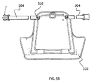
いくつかの実施形態において、また図5Aで示されるように、シート補助装置(100)は、椅子または車椅子などの別のアイテムに容易に固定され得るポータブル装置である。そうする際に、適切な機構または装置を使用して、シート補助装置(100)をそのような椅子に確実に固定することが望ましく、それによって、操作者は、ポータブルシート補助装置(100)を椅子に選択的に固定することができる。限定しない例として、椅子への固定のための土台(102)から伸長するコネクター機構が含まれ得る。また別の限定しない例として、コネクター機構は1対のストラップ固定具(504)であり、該1対のストラップ固定具(504)は、例えば、雄/雌コネクター、あるいは他の適切な機構または装置によって、互いに接続可能である。 In some embodiments, and as shown in FIG. 5A, the seat assistance device (100) is a portable device that can be easily secured to another item, such as a chair or wheelchair. In doing so, it is desirable to securely secure the seat assist device (100) to such a chair using an appropriate mechanism or device so that the operator can attach the portable seat assist device (100). Can be selectively fixed to a chair. As a non-limiting example, a connector mechanism that extends from a base (102) for fixation to a chair may be included. As yet another non-limiting example, the connector mechanism is a pair of strap fasteners (504), such as a male / female connector, or other suitable mechanism or device. Can be connected to each other.
図5Bは、例えば、1対のストラップ固定具(504)を備えた土台(102)を描写している。いくつかの実施形態では、ストラップ固定具(504)は、ねじ(520)またはストラップ固定具(504)が枢動することを可能にするリベットで固定される。
上に留意されるように、ストラップ固定具(504)は、シート補助装置(100)を椅子と固定させるために使用され得る。ストラップ固定具(504)はまた、ユーザー用の安全ベルトとして利用することができ、移動の間のキャリーストラップとして機能することができる。
FIG. 5B depicts a foundation (102) with a pair of strap fasteners (504), for example. In some embodiments, the strap fastener (504) is secured with a screw (520) or a rivet that allows the strap fastener (504) to pivot.
As noted above, the strap fastener (504) can be used to secure the seat assist device (100) to the chair. The strap fastener (504) can also be utilized as a safety belt for the user and can function as a carry strap during travel.
上に留意されるように、シート補助装置(100)は、いくつかの実施形態において、折り畳み位置と待機位置との間および待機位置から持ち上げ位置までの移行のために動作可能である。これらの態様は、図6および7Aでさらに例証される。 As noted above, the seat assist device (100) is operable in some embodiments for the transition between the folded position and the standby position and from the standby position to the lift position. These aspects are further illustrated in FIGS. 6 and 7A.
図6は、例えば、シート補助装置(100)の側面図であり、折り畳み位置(600)から待機位置(602)へのシート補助装置(100)の移行を表す。幾つかの実施形態において、スライド(604)が備わっている。スライド(604)は、リフトアーム(106)に摺動自在に接続されることで、リフトアーム(106)の長さに沿った摺動動作をもたらす。重要なことに、リフトバー(108)は、(リフトバー(108)をリフトアーム(106)と実質的に枢動自在且つ摺動自在に接続する)一端でスライド(604)に枢動自在に接続され、他端で土台(102)に枢動自在に接続される。スライド(604)は、リフトバーの接続点(606)を、リフトアーム(106)に対して前方(608)及び後方(610)へと摺動させるために操作自在である、任意の適切な機構又は装置である。限定されない例として、スライド(604)は、スライド(604)が前方(608)及び後方(610)に摺動するのを可能にするためにリフトアーム(106)の一部の周囲に位置する、円筒状の穴を持つスリーブ(例えば、プラスチック、金属、等)である。故に、折り畳み位置(600)にある場合、スライド(604)はシート補助装置(100)の後方に引っ張られる(摺動される)。折り畳み位置(600)から待機位置(602)へ移行させるために、ハンドル(112)は、前方(608)にスライド(604)を引き付けるように、持ち上げられる(614)。スライド(604)は、滑り止め(420)(図4にも示される)に到達するまで進み続ける。滑り止め(420)は、スライド(604)の前方(608)への動作を制限するために操作自在な任意の適切な機構又は装置であり、その制限されない例は、スライド(604)又はハンドルグリップ(612)に係合するようハンドル(112)に近接して形成される、突起である。図1に表されるように、スライド(604)は随意に、スライドロック(130)を備えており、これは、ロック戻り止めタブ又は他の適切なロック装置などの任意の適切なロック機構である。故に、幾つかの実施形態において、スライド(604)は単に滑り止め(420)(突起又は他の停止装置など)を止めるだけであり、一方で幾つかの実施形態において、シート補助装置(100)は、スライドロック(130)の代わりに、又はこれに連動した戻り止め(420)を備えている。スライドロック(130)は、例えば、スライド(604)の真下に押し下げられるロック戻り止めを持つ、スライド(604)の少なくとも片面に穴を備えている。スライド(604)にある穴がロック戻り止めと位置を合わされると、ロック戻り止めが飛び出し、係合してスライド(604)をロックする。 FIG. 6 is a side view of the seat assisting device (100), for example, showing the transition of the seat assisting device (100) from the folding position (600) to the standby position (602). In some embodiments, a slide (604) is provided. The slide (604) is slidably connected to the lift arm (106) to provide a sliding motion along the length of the lift arm (106). Significantly, the lift bar (108) is pivotally connected to the slide (604) at one end (which connects the lift bar (108) with the lift arm (106) substantially pivotably and slidably). The other end is pivotally connected to the base (102). The slide (604) may be any suitable mechanism operable to slide the lift bar connection point (606) forward (608) and backward (610) relative to the lift arm (106) or Device. By way of non-limiting example, the slide (604) is located around a portion of the lift arm (106) to allow the slide (604) to slide forward (608) and rearward (610). A sleeve having a cylindrical hole (eg, plastic, metal, etc.). Therefore, when in the folded position (600), the slide (604) is pulled (slid) to the rear of the seat auxiliary device (100). To transition from the folded position (600) to the standby position (602), the handle (112) is raised (614) to attract the slide (604) forward (608). Slide (604) continues to travel until it reaches anti-slip (420) (also shown in FIG. 4). The anti-slip (420) is any suitable mechanism or device operable to limit the forward (608) movement of the slide (604), non-limiting examples of which are the slide (604) or handle grip A protrusion formed proximate to the handle (112) to engage (612). As represented in FIG. 1, the slide (604) optionally comprises a slide lock (130), which can be any suitable locking mechanism such as a locking detent tab or other suitable locking device. is there. Thus, in some embodiments, the slide (604) simply stops the anti-slip (420) (such as a protrusion or other stop device), while in some embodiments, the seat assist device (100). Includes a detent (420) instead of or in conjunction with the slide lock (130). The slide lock (130) has a hole on at least one side of the slide (604), for example, having a lock detent that is pushed down just below the slide (604). When the hole in the slide (604) is aligned with the lock detent, the lock detent pops out and engages to lock the slide (604).
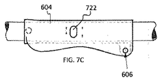
これは、図7B乃至7Gで更に示される。具体的には、図7Bは、解除位置にあるスライドロックを表す、スライド(604)及びスライドロックの平面図である。示されるように、スライドロックは、リフトアーム(106)内に位置する、ばね懸架式の戻り止め(720)を備えている。図7Cの側面図において、スライドロックが、スライド(604)の壁を通って形成された穴(722)を備えていることが示されている。また、リフトバーのための接続点(606)として機能する、スライド(604)を通って形成された穴も示される。例えば、接続点(606)でリフトバーを固定するためにダウエルピンが使用され得、これによりリフトバーをスライド(604)に枢動自在に接続する。リフトバーを土台に枢動自在に接続するために、同様のダウエルピンがリフトバーの他端で随意に使用され得る。 This is further illustrated in FIGS. 7B-7G. Specifically, FIG. 7B is a plan view of the slide (604) and slide lock representing the slide lock in the release position. As shown, the slide lock includes a spring suspended detent (720) located in the lift arm (106). In the side view of FIG. 7C, the slide lock is shown to include a hole (722) formed through the wall of the slide (604). Also shown is a hole formed through the slide (604) that serves as a connection point (606) for the lift bar. For example, dowel pins may be used to secure the lift bar at the connection point (606), thereby pivotally connecting the lift bar to the slide (604). A similar dowel pin can optionally be used at the other end of the lift bar to pivotally connect the lift bar to the foundation.
スライドロックを再び参照すると、図7Dは、リフトアーム(106)内で押しつけられたばね懸架式の戻り止め(720)を表わす、スライド(604)とスライドロックの断面図、正面図を提供している。 Referring again to the slide lock, FIG. 7D provides a cross-sectional, front view of the slide (604) and slide lock, representing a spring suspended detent (720) pressed in the lift arm (106). .
ユーザーがスライド(604)を適所に摺動させると、ばね懸架式の戻り止め(720)は穴(722)を通過し、スライド(604)を適所にロックすることが可能となる。これは、図7E乃至7Gで更に表される。具体的に、図7E、7F、及び7Gはそれぞれ、平面図、側面図、及び断面正面図であり、穴(722)を通ってスライド(604)を適所にロックするばね懸架式の戻り止め(720)を表わしている。 When the user slides the slide (604) in place, the spring suspended detent (720) passes through the hole (722), allowing the slide (604) to lock in place. This is further represented in FIGS. 7E-7G. Specifically, FIGS. 7E, 7F, and 7G are a plan view, a side view, and a cross-sectional front view, respectively, that are spring-suspended detents that lock the slide (604) in place through the hole (722). 720).
図6を再び参照すると、一旦ハンドル(112)が持ち上げられ、スライド(604)が止められると、シート補助装置(100)は、ユーザーを持ち上げ又は降ろすための待機状態にある(即ち、待機位置(602))。 Referring again to FIG. 6, once the handle (112) is lifted and the slide (604) is stopped, the seat assist device (100) is in a standby state to lift or lower the user (ie, the standby position ( 602)).
図7Aは、シート補助装置(100)の側面図であり、待機位置(602)から持ち上げ位置(620)へのシート補助装置(100)の移行を表す。上述のように、ハンドル(112)を下方(114)に押し下げると、リフトアーム(106)の後部(111)は、上方(116)に推し進められ、次に、リフトバー(108)によりもたらされる支点により、リフトプラットフォーム(104)の後部(107)を持ち上げ位置(620)に持ち上げる。また、リフトアーム(106)とリフトプラットフォーム(104)の上方(116)の動きを制限する、制限ストラップ(122)も示される。 FIG. 7A is a side view of the seat assisting device (100) showing the transition of the seat assisting device (100) from the standby position (602) to the lifted position (620). As described above, when the handle (112) is pushed down (114), the rear (111) of the lift arm (106) is pushed upward (116) and then by the fulcrum provided by the lift bar (108). Lift the rear (107) of the lift platform (104) to the lift position (620). Also shown is a restriction strap (122) that restricts the movement (116) of the lift arm (106) and lift platform (104) above (116).
更なる理解のために、図8A乃至8Dは、折り畳み位置(600)から持ち上げ位置(620)に移行する、ユーザーにより操作されているシート補助装置(100)を示している。図8Aは、例えば、上に座っているユーザーにより折り畳み位置(600)にある、椅子(800)の上に位置するシート補助装置(100)を表す。シート補助装置(100)がストラップ固定具(504)を介して椅子(800)に固定されていることに注意されたい。 For further understanding, FIGS. 8A-8D show the seat assistance device (100) being operated by the user transitioning from the folded position (600) to the lifted position (620). FIG. 8A represents a seat assistance device (100) located on a chair (800), for example, in a folded position (600) by a user sitting on it. Note that the seat assistance device (100) is secured to the chair (800) via the strap fastener (504).
図8Bに示されるように、ユーザー(802)がハンドル(112)を持ち上げると(614)、スライド(604)は、戻り止めを介して停止位置に到達するまで前方(608)に引き付けられる。その時点で、シート補助装置(100)は待機位置(602)にある。 As shown in FIG. 8B, when the user (802) lifts the handle (112) (614), the slide (604) is attracted forward (608) through the detent until it reaches the stop position. At that time, the seat auxiliary device (100) is in the standby position (602).
図8Cに示されるように、ユーザー(802)がハンドル(112)を下方(114)に押し下げると、リフトプラットフォーム(104)は持ち上げ位置(620)へと上方(116)に推し進められ、その状態から、ユーザーは図8Dに示されるように立つことができる。具体的には、図8Dは、ユーザー(802)を持ち上げた後に待機位置(602)にある、椅子(800)の上に位置するシート補助装置(100)を表す。故に、ユーザー(802)はその後、図8A乃至8Cに示されるプロセスの順序を逆に用いて、着座位置に下げられ得る。 As shown in FIG. 8C, when the user (802) depresses the handle (112) downward (114), the lift platform (104) is pushed upward (116) to the lifted position (620) and from that state. The user can stand as shown in FIG. 8D. Specifically, FIG. 8D represents the seat assistance device (100) located on the chair (800) in the standby position (602) after lifting the user (802). Thus, the user (802) can then be lowered to the seated position using the process sequence shown in FIGS. 8A-8C in reverse.
シート補助装置(100)は、本発明の原理に応じて、様々な用途で使用且つ実施され得ることに、注目されたい。例えば、図9は、ユーザー(802)が椅子(800)から立ち上るのを補助する介護者(900)によりシート補助装置(100)が作動される態様を表す図である。 It should be noted that the seat assist device (100) can be used and implemented in a variety of applications in accordance with the principles of the present invention. For example, FIG. 9 is a diagram illustrating a mode in which the seat assisting device (100) is operated by the caregiver (900) who assists the user (802) to get up from the chair (800).
また別の例として、図10は、便器(1000)からユーザーを持ち上げるために、便座にシート補助装置(100)が組み込まれる態様を表す図である。この態様において、例えば、リフトバー(108)は随意に待機位置に固定され、一方でリフトプラットフォーム(104)は、機能的な便座として操作するために実際の便座(穴が貫通している)の形状に形成される。土台(102)は、便器とボルトの形状に一致するように形成且つ成形されるか、又はそうでなければ便器に固定され得る。例えば、土台(102)は、実際の便器の上にある便座ボルト穴と位置を合わせるボルト又はボルト穴を有しており、それによりユーザーは、そのような装置を従来の便座の適所で、便器に容易に固定することができる。リフトアーム(106)は、表わされているように、ハンドル(112)を操作するよう形成され得る。上述の事例のように、ハンドル(112)を下方(114)に押し下げると、リフトプラットフォーム(104)(即ち便座)の後部は上方(116)に持ち上げられる。随意に、ロック装置(1002)がこの態様及び他の態様に含まれる。ロック装置(1002)は、様々な位置の間での移行(この例では、待機位置から持ち上げ位置)を防ぐために、シート補助装置をロックするために操作自在な任意の適切な機構又は装置である。限定されない例として、ロック装置(1002)は、リフトアーム(106)を通って伸び、且つリフトプラットフォーム(104)の後部上の対応する留め金(catch)と着脱自在に取り付け可能なラッチに接続するケーブルを持つ、ブレーキレバーを備えている。例えば、ユーザーがレバーを握り締める場合、ラッチは留め金から引っ張られ、ユーザーがハンドル(112)を下方(114)に押し下げるのを可能にし;そうでなければ、リフトアームは示されるように待機位置にロックされる。 As another example, FIG. 10 is a diagram illustrating a mode in which the seat auxiliary device (100) is incorporated in the toilet seat in order to lift the user from the toilet (1000). In this embodiment, for example, the lift bar (108) is optionally fixed in the standby position, while the lift platform (104) is shaped as a real toilet seat (holes penetrated) to operate as a functional toilet seat. Formed. The foundation (102) can be formed and shaped to match the shape of the toilet bowl and bolt, or otherwise secured to the toilet bowl. For example, the base (102) has bolts or bolt holes that align with the toilet seat bolt holes on the actual toilet, so that the user can place such devices in place on a conventional toilet seat. Can be fixed easily. The lift arm (106) may be configured to manipulate the handle (112) as shown. As in the case described above, when the handle (112) is depressed downward (114), the rear portion of the lift platform (104) (ie toilet seat) is lifted upward (116). Optionally, a locking device (1002) is included in this and other aspects. The locking device (1002) is any suitable mechanism or device that is operable to lock the seat assistance device to prevent transitions between various positions (in this example, the lifted position from the standby position). . As a non-limiting example, the locking device (1002) extends through the lift arm (106) and connects to a corresponding catch on the rear of the lift platform (104) and a releasably attachable latch. It has a brake lever with a cable. For example, when the user squeezes the lever, the latch is pulled from the clasp and allows the user to push the handle (112) down (114); otherwise, the lift arm is in the standby position as shown. Locked.
また別の例として、及び図11に表されるように、シート補助装置(100)は、従来の便器の上に位置し得る(又は、真下に位置付けられる寝室用便器を有する)便座椅子に組み込むことができる。この態様は、図11の土台(102)が椅子それ自体として操作するために付加的なフレーム部材(1100)(例えば、金属チューブ、又は必要とされるような任意の他のフレーム構成要素)を備えていることを除いて、図10に示されるものと同様である。例えば、及び図12に示されるように、シート補助装置(100)は、従来の便器(1000)上に位置させるために便座椅子として作用し得る。 As yet another example, and as depicted in FIG. 11, the seat assistance device (100) is incorporated into a toilet seat chair that may be positioned above a conventional toilet bowl (or having a bedroom toilet bowl positioned directly below). be able to. This embodiment allows additional frame members (1100) (eg, metal tubes or any other frame components as required) for the base (102) of FIG. 11 to operate as a chair itself. Except for the provision, it is the same as that shown in FIG. For example, and as shown in FIG. 12, the seat assistance device (100) may act as a toilet seat chair for positioning on a conventional toilet bowl (1000).
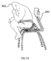
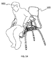
例えば、及び図13、14、及び15に示されるように、ユーザー(802)は、シート補助装置(100)を使用して、着座位置から起立位置に立ち上がることができる(又は、逆の順序で座ることができる)。 For example, and as shown in FIGS. 13, 14, and 15, the user (802) can use the seat assist device (100) to stand up from the sitting position to the standing position (or in reverse order). Can sit down).
シート補助装置(100)の別の例が図16に表される。図16に表された実施形態は、上述のような態様と同様に作動するが、しかし、土台(102)は再び、脚部や背もたれなどを含む実際の椅子それ自体を形成するために、付加的なフレーム部材(1600)を備えている。故に、この態様において、シート補助装置(100)は椅子に組み込まれている。クッションは、別々に形成され、且つリフトプラットフォーム(104)に取り付けられ得、或いは、リフトプラットフォーム(104)自体の上には、シートクッションが形成される場合がある。また、椅子は随意に、ホイール(1602)及びハンドル(1604)を備えており、それにより、介護者又は他の個人は、背もたれを傾けて、椅子に可動性をもたらすことができる。そのようなシート補助装置(100)はまた、同様の機能をもたらすために車椅子に直接構築され得ることを、理解されたい。 Another example of the seat auxiliary device (100) is shown in FIG. The embodiment depicted in FIG. 16 operates in a manner similar to that described above, but the base (102) is again added to form the actual chair itself, including the legs, backrest, etc. A typical frame member (1600) is provided. Therefore, in this embodiment, the seat auxiliary device (100) is incorporated in the chair. The cushion may be formed separately and attached to the lift platform (104), or a seat cushion may be formed on the lift platform (104) itself. The chair also optionally includes a wheel (1602) and a handle (1604) so that a caregiver or other individual can tilt the back and provide mobility to the chair. It should be understood that such a seat assistance device (100) can also be built directly into a wheelchair to provide a similar function.
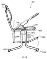
シート補助装置(100)の別の例が図17に表わされ、これは、肘掛けの無い椅子又は食卓椅子、或いはオフィスのデスク用の椅子に向けられている。図17に表された実施形態は、上述のような態様と同様に作動するが、しかし、土台(102)は再び、脚部や背もたれなどを含む実際の椅子それ自体を形成するために、付加的なフレーム部材(1700)を備えている。この態様において、例えば、シート補助装置(100)は、(従来のデスク用椅子と同様の)垂直調整機能をもたらす、ガスピストン(1700)を備えている。調整自在な背中支持部(1702)が、中心の柱(1705)により付与される旋回動作(1704)に沿って備わる場合がある。床面プラットフォーム(1706)が、床面でシート補助装置(100)を安定させるために備わっている。幾つかの実施形態において、自分自身を持ち上げるためにシート補助装置(100)を使用する場合に、更なる安定性のための床面プラットフォーム(1706)の底面上にスライド(1708)(対立するものとして、ホイール)が備わっている。温パック又は冷パックを提供するために、背もたれにポケット(1710)も備わっている場合がある。未使用時に、ハンドル(112)は、不適当に揺れるか、又はリフトアーム(106)の上でひっくり返る(flipped back)(1712)場合がある。 Another example of a seat assistance device (100) is depicted in FIG. 17, which is directed to a chair or table chair without an armrest, or a chair for an office desk. The embodiment depicted in FIG. 17 operates in a manner similar to that described above, but the base (102) is again added to form the actual chair itself, including the legs, backrest, etc. A typical frame member (1700) is provided. In this aspect, for example, the seat assistance device (100) includes a gas piston (1700) that provides a vertical adjustment function (similar to a conventional desk chair). An adjustable back support (1702) may be provided along the pivoting motion (1704) provided by the central column (1705). A floor platform (1706) is provided to stabilize the seat assistance device (100) on the floor. In some embodiments, when using the seat assistance device (100) to lift itself, the slide (1708) (opposed) on the bottom surface of the floor platform (1706) for further stability As a wheel). The backrest may also be provided with a pocket (1710) to provide a warm pack or a cold pack. When not in use, the handle (112) may swing improperly or flipped back (1712) on the lift arm (106).
更に、リフトプラットフォーム(104)は、ユーザーが快適に座ることができるシートとして作動する。自分自身を持ち上げることが所望される場合、ユーザーは、ハンドル(112)を単純に押し下げることができ、それにより、リフトプラットフォーム(104)の前部(109)が土台(102)に枢動自在に接続されるので、リフトプラットフォーム(104)(即ち、椅子シート)の後部(107)は持ち上げられ(116)、そして前方に傾けられる。 Furthermore, the lift platform (104) operates as a seat that allows the user to sit comfortably. If it is desired to lift himself, the user can simply depress the handle (112) so that the front (109) of the lift platform (104) is pivotable to the base (102). As connected, the rear (107) of the lift platform (104) (ie chair seat) is lifted (116) and tilted forward.
シート補助装置(100)の別の例が図18に表され、これは、シート補助装置(100)を作動させるために別の人がフットペタル(1800)を押し下げることができる、介護者向け装置に向けられる。図18に表された実施形態は、上述のような態様と同様に作動するが、しかし、土台(102)は再び、脚部や背もたれなどを含む実際の椅子それ自体を形成するために、付加的なフレーム部材(1801)を備えている。付加的に、第1のリンク機構(1802)は、枢動点(1804)の周囲で回転するフットペタル(1800)に接続される。第1のリンク機構(1802)は真っ直ぐであり、又は示されるように、付加的な持ち上げをもたらすように曲がっていてもよい。リフトリンク機構(1806)は、第1のリンク機構(1802)に枢動自在に接続される。望ましいように、リフトリンク機構(1806)はまた、(リフトプラットフォーム(104)(例えばシート)の後部に直接接続されているが)リフトアーム(106)に接続される。故に、フットペダル(1800)が押し下げられると、第1のリンク機構(1802)は、リフトリンク機構(1806)を持ち上げるために第1のリンク機構(1802)の周囲を枢動し、次に、(上述及び本明細書全体に記載される同じ機構に従い)リフトプラットフォーム(104)を持ち上げる。随意の追加物は、椅子の脚部に取り付けられたホイール(1602)とスライド(1708)に沿って、背もたれに形成されたハンドグリップ(1808)(又はハンドル)を備えている。 Another example of a seat assist device (100) is depicted in FIG. 18, which is a caregiver device that allows another person to push down the foot petal (1800) to activate the seat assist device (100). Directed. The embodiment depicted in FIG. 18 operates in a manner similar to that described above, but the base (102) is again added to form the actual chair itself, including the legs, backrest, etc. A typical frame member (1801) is provided. Additionally, the first linkage (1802) is connected to a foot petal (1800) that rotates about a pivot point (1804). The first linkage (1802) is straight or may be bent to provide additional lifting, as shown. The lift link mechanism (1806) is pivotally connected to the first link mechanism (1802). As desired, the lift linkage (1806) is also connected to the lift arm (106) (although directly connected to the rear of the lift platform (104) (eg, seat)). Thus, when the foot pedal (1800) is depressed, the first linkage (1802) pivots around the first linkage (1802) to lift the lift linkage (1806), and then Lift the lift platform (104) (according to the same mechanism described above and throughout the specification). Optional additions include a handgrip (1808) (or handle) formed on the backrest along the wheel (1602) and slide (1708) attached to the leg of the chair.
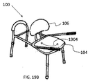
シート補助装置(100)の別の例が図19Aと19Bに表わされ、これは、シャワー用移動シートに向けられる。図19Aと19Bに表された実施形態は、上述のような態様と同様に作動するが、しかし、土台(102)は、実際のシャワー用移動シートを形成するために再度付加的なフレーム部材(1900)を備えている。この態様において、土台(102)は、浴槽又はシャワーの中を摺動する(1902)ことができるように、付加的なフレーム部材(1900)に摺動自在に接続される。限定されない例として、土台(102)は、土台(102)及び付加的なフレーム部材(1900)に、及びそれらの間に接続される、回転台及びスリーブを持つプラットフォームを備えている。スリーブは土台(102)を摺動させ(1902)、一方で回転台は土台を回転させ(1904)、実際にはリフトプラットフォーム(104)とリフトアーム(106)を回転させる。 Another example of a seat assistance device (100) is depicted in FIGS. 19A and 19B, which is directed to a shower moving seat. The embodiment depicted in FIGS. 19A and 19B operates in a manner similar to that described above, but the base (102) is again provided with additional frame members (to form the actual shower transfer sheet). 1900). In this aspect, the base (102) is slidably connected to an additional frame member (1900) so that it can slide (1902) in a bathtub or shower. As a non-limiting example, the base (102) comprises a platform with a turntable and a sleeve connected to and between the base (102) and additional frame members (1900). The sleeve slides the base (102) (1902), while the rotating base rotates the base (1904) and actually rotates the lift platform (104) and lift arm (106).
本発明の様々な態様が図示され且つ記載されてきた一方、様々な修正がなされ得ることが理解される。従って、本発明は開示された実施形態には限定されないが、むしろ、当業者に明白であり且つ本発明の精神及び範囲内にある全ての実施形態を含むことが意図されていることを、理解されたい。 While various aspects of the invention have been illustrated and described, it will be appreciated that various modifications can be made. Accordingly, it is to be understood that the invention is not limited to the disclosed embodiments, but rather is intended to include all embodiments that will be apparent to those skilled in the art and are within the spirit and scope of the invention. I want to be.
Claims (18)
土台、
前部と後部を有するリフトプラットフォームであって、リフトプラットフォームの前部が土台に枢動自在に接続される、リフトプラットフォーム、
リフトプラットフォームの後部に接続されるリフトアームであって、リフトアームがリフトプラットフォームの前部を越えて突出するようにリフトプラットフォームから伸び、リフトアームがユーザーによって把持されるハンドルで終了する、リフトアーム、ならびに、
土台とリフトアームとの間で枢動自在に接続されるリフトバーであって、それによって、シート補助装置に座っているユーザーがハンドルを押し下げることでリフトプラットフォームの後部を上昇させることができ、その際にユーザーが着座位置から立ち上がるのを補助する、リフトバー、
を備える、シート補助装置。 A seat auxiliary device,
Foundation,
A lift platform having a front portion and a rear portion, wherein the front portion of the lift platform is pivotally connected to a base;
A lift arm connected to the rear of the lift platform, the lift arm extending from the lift platform such that the lift arm projects beyond the front of the lift platform, and the lift arm ends with a handle that is gripped by a user; And
A lift bar that is pivotally connected between the base and the lift arm so that the user sitting on the seat assistance device can raise the rear of the lift platform by pushing down on the handle, A lift bar that helps the user to get up from the seating position,
A seat auxiliary device.
リフトバーがスライドに枢動自在に接続され、それによってリフトバーをリフトアームに枢動自在に接続する、請求項1に記載のシート補助装置。 A slide that is slidably connected to the lift arm;
The seat assisting device of claim 1, wherein the lift bar is pivotally connected to the slide, thereby pivotally connecting the lift bar to the lift arm.
制限ストラップはリフトプラットフォームの後部の上方への動きを制限するように動作可能である、請求項2に記載のシート補助装置。 Further comprising a limiting strap connected to and between the base and the lift arm,
The seat assistance apparatus of claim 2, wherein the restraining strap is operable to restrict upward movement of the rear portion of the lift platform.
ピンチガードは、リフトプラットフォームと土台の間で指をはさまれないようにするために、リフトバーに近接して配される、請求項3に記載のシート補助装置。 It is further equipped with a pinch guard attached to the base,
4. The seat assisting device according to claim 3, wherein the pinch guard is disposed close to the lift bar so as not to pinch a finger between the lift platform and the base.
滑り止めはスライドの前方への動きを防ぐためのリフトアーム上の突起である、請求項4に記載のシート補助装置。 Further equipped with a non-slip attached to the lift arm,
The seat auxiliary device according to claim 4, wherein the non-slip is a protrusion on a lift arm for preventing the slide from moving forward.
スライドロックはリフトアームに対して適所にスライドを選択的にロックするために形成される、請求項6に記載のシート補助装置。 Further equipped with a slide lock attached to the lift arm,
The seat assisting device of claim 6, wherein the slide lock is formed to selectively lock the slide in place relative to the lift arm.
制限ストラップはリフトプラットフォームの後部の上方への動きを制限するように動作可能である、請求項1に記載のシート補助装置。 Further comprising a restriction strap connected to and between the base and the lift arm,
The seat assistance apparatus of claim 1, wherein the restraining strap is operable to restrict upward movement of the rear portion of the lift platform.
滑り止めはスライドの前方への動きを防ぐためのリフトアーム上の突起である、請求項1に記載のシート補助装置。 Further equipped with a non-slip attached to the lift arm,
The seat auxiliary device according to claim 1, wherein the non-slip is a protrusion on the lift arm for preventing the slide from moving forward.
スライドロックはリフトアームに対して適所にスライドを選択的にロックするために形成される、請求項1に記載のシート補助装置。 Further equipped with a slide lock attached to the lift arm,
The seat assisting device according to claim 1, wherein the slide lock is formed to selectively lock the slide in place relative to the lift arm.
Applications Claiming Priority (5)
| Application Number | Priority Date | Filing Date | Title |
|---|---|---|---|
| US201462070815P | 2014-09-08 | 2014-09-08 | |
| US62/070,815 | 2014-09-08 | ||
| US201562179713P | 2015-05-18 | 2015-05-18 | |
| US62/179,713 | 2015-05-18 | ||
| PCT/US2015/048576 WO2016040164A1 (en) | 2014-09-08 | 2015-09-04 | Seat assist device |
Publications (1)
| Publication Number | Publication Date |
|---|---|
| JP2017532097A true JP2017532097A (en) | 2017-11-02 |
Family
ID=54140736
Family Applications (1)
| Application Number | Title | Priority Date | Filing Date |
|---|---|---|---|
| JP2017512994A Pending JP2017532097A (en) | 2014-09-08 | 2015-09-04 | Seat assist device |
Country Status (6)
| Country | Link |
|---|---|
| US (3) | US9918886B2 (en) |
| EP (1) | EP3191063B1 (en) |
| JP (1) | JP2017532097A (en) |
| CN (1) | CN107205593B (en) |
| ES (1) | ES2865874T3 (en) |
| WO (1) | WO2016040164A1 (en) |
Cited By (1)
| Publication number | Priority date | Publication date | Assignee | Title |
|---|---|---|---|---|
| JP2023082938A (en) * | 2021-12-03 | 2023-06-15 | カネタコーポレーション株式会社 | transfer device |
Families Citing this family (18)
| Publication number | Priority date | Publication date | Assignee | Title |
|---|---|---|---|---|
| EP3191063B1 (en) * | 2014-09-08 | 2021-02-17 | Splane Design Associates, Inc. | Seat assist device |
| WO2016106169A1 (en) * | 2014-12-22 | 2016-06-30 | Innovations Us Llc | Seating apparatus and methods of using the same |
| US11020300B2 (en) * | 2015-04-13 | 2021-06-01 | Jeff Wiewiura | Toilet safety arm accessory device |
| EP3310314B1 (en) * | 2015-06-19 | 2022-10-26 | Senior Life LLC | Lift-assist chair |
| TWI629029B (en) * | 2016-09-26 | 2018-07-11 | 國立臺北科技大學 | Auxiliary seat |
| DE102017114813B4 (en) * | 2017-07-03 | 2019-02-07 | René Heller | RESTORED TOILET SEAT |
| US10449100B2 (en) | 2017-10-26 | 2019-10-22 | Francis Norbert Hector, Jr. and Karolyn M. Hector | Lift assist chair |
| CN109730574B (en) * | 2019-01-31 | 2021-07-06 | 青岛阿玛苏康养医疗有限公司 | A kind of medical toilet and using method thereof |
| US20200245827A1 (en) * | 2019-02-04 | 2020-08-06 | Chan Hur | Toilet seat |
| KR102062486B1 (en) * | 2019-04-01 | 2020-01-03 | 송순영 | Apparatus for assisting the standing of toilet seat users |
| US11590378B2 (en) | 2020-03-25 | 2023-02-28 | Robert S. Thurman | Exercise chair |
| IT202100003497A1 (en) * | 2021-02-16 | 2022-08-16 | Easyseat S R L | "EASY SEAT" ERGONOMIC AND REMOVABLE SEAT WITH GREEN GEARS TO IMPROVE THE POSTURE OF ITS USERS |
| EP4346531A4 (en) * | 2021-06-03 | 2025-05-14 | Home Furnishings Resource Group Inc. D/B/A F3 | BATHROOM LIFTING AID DEVICE |
| US12594202B2 (en) | 2021-08-13 | 2026-04-07 | Direct Supply, Inc. | Seat lift with non-linear spring assist |
| AT525504A1 (en) * | 2021-09-22 | 2023-04-15 | Joka Kapsamer Gmbh | Seating furniture with a stand-up aid |
| TWI789076B (en) * | 2021-10-26 | 2023-01-01 | 興友科技股份有限公司 | Body Composition Analysis System with Image Scanning Function |
| JP2023102228A (en) * | 2022-01-11 | 2023-07-24 | 諭 西村 | Anyone can easily stand up easily and reduce assist |
| CN116831828A (en) * | 2023-06-25 | 2023-10-03 | 刘磊 | Helping hand chair of getting up |
Family Cites Families (49)
| Publication number | Priority date | Publication date | Assignee | Title |
|---|---|---|---|---|
| US3259427A (en) * | 1965-10-18 | 1966-07-05 | Ray S Wiest | Leverage seat lifts |
| US3679260A (en) | 1970-05-21 | 1972-07-25 | Bath Inst Of Medical Eng The | Invalid chairs |
| SE376545B (en) * | 1973-10-05 | 1975-06-02 | Landstingens Inkopscentral | |
| US4688851A (en) | 1986-02-07 | 1987-08-25 | Henry E. Allen | Seating assist device with adjustable spring assembly |
| SE455990B (en) | 1986-12-29 | 1988-08-29 | Electrolux Ab | PATIENT LIFTING |
| FR2639807A1 (en) * | 1988-12-01 | 1990-06-08 | Jouk Leon | Chair with pivoting seat |
| US4929022A (en) * | 1989-02-23 | 1990-05-29 | Alexander Geraci | Chair having lift apparatus |
| US5082327A (en) | 1990-10-19 | 1992-01-21 | Crisp Charles D | Lift apparatus for use with a chair |
| US5445431A (en) | 1991-09-13 | 1995-08-29 | Johnston; Gary | Seat uplift apparatus |
| US6270159B1 (en) | 1991-09-13 | 2001-08-07 | Gary L. Johnston | Manual uplift apparatus |
| US5346280A (en) * | 1992-03-31 | 1994-09-13 | Deumite Norman A | Chair with automatic standing aid |
| US5316370A (en) | 1992-11-16 | 1994-05-31 | Newman Engineering Inc. | Seat assist |
| GB2282062B (en) | 1993-09-14 | 1997-08-06 | John Alfred Hooker | Seat Unit |
| US5423280A (en) | 1993-11-24 | 1995-06-13 | Kelley; Michael A. | Seat hinge |
| US5918936A (en) | 1997-02-14 | 1999-07-06 | Murphy; Lloyd F. | Seat lift mechanism |
| US5816655A (en) | 1997-02-20 | 1998-10-06 | Hoegh; Poul E. | Armchair with seatlift |
| WO1998041136A2 (en) * | 1997-03-19 | 1998-09-24 | Moser Scott A | Energy transferring toilet seat |
| US6035462A (en) * | 1997-10-29 | 2000-03-14 | Lenjoy Engineering, Inc. | Portable commode seat with lift assist |
| US6199228B1 (en) * | 1999-03-31 | 2001-03-13 | William F. Kallweit | Height adjustable toilet seat |
| US6360382B1 (en) * | 1999-04-05 | 2002-03-26 | Karding, Inc. | Powered toilet seat lift |
| US6189164B1 (en) * | 1999-10-27 | 2001-02-20 | Jon A. Krapu | Toilet seat elevating system |
| JP2003019055A (en) * | 2001-07-11 | 2003-01-21 | Komura Seisakusho:Kk | Lifting chair |
| US6637818B2 (en) | 2001-08-24 | 2003-10-28 | Jerry Wayne Williams | Portable lift seat apparatus |
| US7247128B2 (en) * | 2002-04-03 | 2007-07-24 | Oga Co., Ltd. | Exercise assisting machine |
| US20040021354A1 (en) | 2002-07-31 | 2004-02-05 | Hogg Mark G. | Tiltable spring-biased chair |
| PL361394A1 (en) | 2003-07-22 | 2005-01-24 | Stanisław Grabowski | Rehabilitation and rest chair |
| WO2005018522A1 (en) | 2003-08-18 | 2005-03-03 | Steven Phillip Corcoran | Raiser seat |
| US6945604B2 (en) | 2003-11-18 | 2005-09-20 | Lifegear, Inc. | Lifting toilet chair |
| US20050200180A1 (en) | 2004-03-12 | 2005-09-15 | Akron General Development Foundation | Self-contained air lifted seat apparatus |
| IL162582A0 (en) * | 2004-06-17 | 2005-11-20 | Ya Akov Gabel | An exercise and mobilization device for motorically handicapped persons |
| JP2008540020A (en) * | 2005-05-17 | 2008-11-20 | オハド パズ, | Multi-position support device with electric foot support |
| US20060284462A1 (en) * | 2005-06-15 | 2006-12-21 | Cheng Yu W | Medical chair |
| DE102005038030B4 (en) * | 2005-08-08 | 2007-08-09 | Otto Bock Healthcare Ip Gmbh & Co. Kg | Stand-up wheelchair |
| US7594698B1 (en) | 2007-10-17 | 2009-09-29 | Marge Palmer | Portable seat for a wheelchair |
| US8011732B2 (en) * | 2009-04-15 | 2011-09-06 | Honda Motor Co., Ltd. | Tiltable anti-pinch seat assembly and pinch guard |
| FI20105532A0 (en) * | 2010-05-14 | 2010-05-14 | Jorma Eerola | Seat device |
| KR101038579B1 (en) * | 2010-05-31 | 2011-06-03 | 박원석 | A chair that is easy to sit and stand up |
| JP5827500B2 (en) | 2010-09-01 | 2015-12-02 | デルタ工業株式会社 | Seat lifter and seat |
| US20120126601A1 (en) | 2010-11-18 | 2012-05-24 | Smith Vincent J | System, method and apparatus for assisting with standing from a seat |
| US8287048B2 (en) * | 2010-12-21 | 2012-10-16 | Keiper Gmbh & Co. Kg | Pinch guard for a vehicle seat |
| US8398171B2 (en) * | 2011-01-14 | 2013-03-19 | Cycling & Health Tech Industry R & D Center | Lift chair |
| WO2012170863A2 (en) * | 2011-06-09 | 2012-12-13 | Haworth, Inc. | Forward sliding reclining chair |
| CN103717191A (en) * | 2011-07-07 | 2014-04-09 | 罗杰·肯尼斯·莱布 | Patient Useful Seats, Frames and Lifting Garments |
| DE102012102699B4 (en) * | 2012-03-29 | 2013-10-17 | medica - Medizintechnik GmbH | Aufstehtrainer |
| US8646123B1 (en) * | 2012-04-27 | 2014-02-11 | Denis Potvin | Power actuated toilet seat device |
| AT514846A1 (en) * | 2013-09-23 | 2015-04-15 | Camarg Og | seating |
| EP3191063B1 (en) * | 2014-09-08 | 2021-02-17 | Splane Design Associates, Inc. | Seat assist device |
| EP3310314B1 (en) * | 2015-06-19 | 2022-10-26 | Senior Life LLC | Lift-assist chair |
| US9662252B1 (en) * | 2016-10-28 | 2017-05-30 | Donald Pearson | Stand assist apparatus |
-
2015
- 2015-09-04 EP EP15763791.9A patent/EP3191063B1/en not_active Not-in-force
- 2015-09-04 JP JP2017512994A patent/JP2017532097A/en active Pending
- 2015-09-04 WO PCT/US2015/048576 patent/WO2016040164A1/en not_active Ceased
- 2015-09-04 US US14/846,008 patent/US9918886B2/en active Active
- 2015-09-04 CN CN201580060551.XA patent/CN107205593B/en not_active Expired - Fee Related
- 2015-09-04 ES ES15763791T patent/ES2865874T3/en active Active
-
2018
- 2018-03-09 US US15/917,146 patent/US10874564B2/en active Active
-
2019
- 2019-10-14 US US16/601,161 patent/US10881564B2/en active Active
Cited By (2)
| Publication number | Priority date | Publication date | Assignee | Title |
|---|---|---|---|---|
| JP2023082938A (en) * | 2021-12-03 | 2023-06-15 | カネタコーポレーション株式会社 | transfer device |
| JP7818804B2 (en) | 2021-12-03 | 2026-02-24 | カネタコーポレーション株式会社 | Transfer device |
Also Published As
| Publication number | Publication date |
|---|---|
| US20160067125A1 (en) | 2016-03-10 |
| US9918886B2 (en) | 2018-03-20 |
| EP3191063A1 (en) | 2017-07-19 |
| CN107205593B (en) | 2018-11-06 |
| EP3191063B1 (en) | 2021-02-17 |
| US20180325759A1 (en) | 2018-11-15 |
| CN107205593A (en) | 2017-09-26 |
| US10881564B2 (en) | 2021-01-05 |
| ES2865874T3 (en) | 2021-10-18 |
| US20200179196A1 (en) | 2020-06-11 |
| WO2016040164A1 (en) | 2016-03-17 |
| US10874564B2 (en) | 2020-12-29 |
Similar Documents
| Publication | Publication Date | Title |
|---|---|---|
| US10881564B2 (en) | Seat assist device | |
| CA2825296C (en) | Transport chairs | |
| US11642259B2 (en) | Reclining armchair with lifting seat and extending footrest | |
| US7540565B2 (en) | Lift chair | |
| JP2020508704A (en) | Walking aids for the elderly | |
| US10426677B2 (en) | Reclining transport chairs | |
| US9241854B2 (en) | Seat support | |
| US9808386B2 (en) | Seat support | |
| EP3592308B1 (en) | Reclining transport chairs | |
| US7686319B1 (en) | Double amputee conveyance | |
| JP2007089613A (en) | Standing up assistance device and standing up assistance chair | |
| JPH0636443U (en) | Chair with double seat | |
| JPH09168565A (en) | Chair to help user to rise | |
| AU2004205109A1 (en) | A reclining chair with tilting actuator |
Legal Events
| Date | Code | Title | Description |
|---|---|---|---|
| A521 | Request for written amendment filed |
Free format text: JAPANESE INTERMEDIATE CODE: A523 Effective date: 20170328 |